1
Owner’s Manual
Thank you, and congratulations on your choice of the Roland HandSonic HPD-15.
Before using this unit, carefully read the sections entitled: “USING THE UNIT SAFELY”
(p. 2–3) and “IMPORTANT NOTES” (p. 4). These sections provide important information
concerning the proper operation of the unit. Additionally, in order to feel assured that
you have gained a good grasp of every feature provided by your new unit, Owner’s
manual should be read in its entirety. The manual should be saved and kept on hand as a
convenient reference.
* The D Beam Controller is provided under license from Interactive Light, Inc.
Copyright © 2000 ROLAND CORPORATION
All rights reserved. No part of this publication may be reproduced in any form without the
written permission of ROLAND CORPORATION.
For the U.K.
IMPORTANT: THE WIRES IN THIS MAINS LEAD ARE COLOURED IN ACCORDANCE WITH THE FOLLOWING CODE.
BLUE:
NEUTRAL
BROWN: LIVE
As the colours of the wires in the mains lead of this apparatus may not correspond with the coloured markings identifying
the terminals in your plug, proceed as follows:
The wire which is coloured BLUE must be connected to the terminal which is marked with the letter N or coloured BLACK.
The wire which is coloured BROWN must be connected to the terminal which is marked with the letter L or coloured RED.
Under no circumstances must either of the above wires be connected to the earth terminal of a three pin plug.
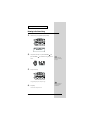
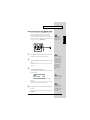
USING THE UNIT SAFELY
The
symbol alerts the user to important instructions
or warnings.The specific meaning of the symbol is
determined by the design contained within the
triangle. In the case of the symbol at left, it is used for
general cautions, warnings, or alerts to danger.
Used for instructions intended to alert
the user to the risk of death or severe
injury should the unit be used
improperly.
Used for instructions intended to alert
the user to the risk of injury or material
damage should the unit be used
improperly.
* Material damage refers
other adverse effects
respect to the home
furnishings, as well
animals or pets.
The
symbol alerts the user to items that must never
be carried out (are forbidden). The specific thing that
must not be done is indicated by the design contained
within the circle. In the case of the symbol at left, it
means that the unit must never be disassembled.
to damage or
caused with
and all its
to domestic
The ● symbol alerts the user to things that must be
carried out. The specific thing that must be done is
indicated by the design contained within the circle. In
the case of the symbol at left, it means that the powercord plug must be unplugged from the outlet.
001
005
• Before using this unit, make sure to read the
instructions below, and the Owner’s Manual.
• This unit should be used only with a rack or stand
that is recommended by Roland.
..........................................................................................................
..........................................................................................................
002c
006
• Do not open (or modify in any way) the unit or its
AC adaptor.
• When using the unit with a rack or stand recommended by Roland, the rack or stand must be
carefully placed so it is level and sure to remain
stable. If not using a rack or stand, you still need
to make sure that any location you choose for
placing the unit provides a level surface that will
properly support the unit, and keep it from
wobbling.
..........................................................................................................
..........................................................................................................
003
• Do not attempt to repair the unit, or replace parts
within it (except when this manual provides
specific instructions directing you to do so). Refer
all servicing to your retailer, the nearest Roland
Service Center, or an authorized Roland
distributor, as listed on the "Information" page.
..........................................................................................................
004
• Never use or store the unit in places that are:
• Subject to temperature extremes (e.g., direct
sunlight in an enclosed vehicle, near a heating
duct, on top of heat-generating equipment); or
are
• Damp (e.g., baths, washrooms, on wet floors);
or are
• Humid; or are
• Exposed to rain; or are
• Dusty; or are
• Subject to high levels of vibration.
..........................................................................................................
2
008c
• Be sure to use only the AC adaptor supplied with
the unit. Also, make sure the line voltage at the
installation matches the input voltage specified on
the AC adaptor’s body. Other AC adaptors may
use a different polarity, or be designed for a
different voltage, so their use could result in
damage, malfunction, or electric shock.
..........................................................................................................
009
• Do not excessively twist or bend the power cord,
nor place heavy objects on it. Doing so can
damage the cord, producing severed elements and
short circuits. Damaged cords are fire and shock
hazards!
..........................................................................................................
010
101b
• This unit, either alone or in combination with an
amplifier and headphones or speakers, may be
capable of producing sound levels that could
cause permanent hearing loss. Do not operate for
a long period of time at a high volume level, or at
a level that is uncomfortable. If you experience
any hearing loss or ringing in the ears, you should
immediately stop using the unit, and consult an
audiologist.
..........................................................................................................
• The unit and the AC adaptor should be located so
their location or position does not interfere with
their proper ventilation.
..........................................................................................................
011
• Do not allow any objects (e.g., flammable material,
coins, pins); or liquids of any kind (water, soft
drinks, etc.) to penetrate the unit.
..........................................................................................................
012c
• Immediately turn the power off, remove the AC
adaptor from the outlet, and request servicing by
your retailer, the nearest Roland Service Center, or
an authorized Roland distributor, as listed on the
"Information" page when:
• The AC adaptor or the power-supply cord has
been damaged; or
• Objects have fallen into, or liquid has been
spilled onto the unit; or
• The unit has been exposed to rain (or otherwise
has become wet); or
• The unit does not appear to operate normally or
exhibits a marked change in performance.
..........................................................................................................
013
• In households with small children, an adult
should provide supervision until the child is
capable of following all the rules essential for the
safe operation of the unit.
..........................................................................................................
014
• Protect the unit from strong impact.
(Do not drop it!)
102d
• Always grasp only the plug or the body of the AC
adaptor when plugging into, or unplugging from,
an outlet or this unit.
..........................................................................................................
103b
• Whenever the unit is to remain unused for an
extended period of time, disconnect the AC
adaptor.
..........................................................................................................
104
• Try to prevent cords and cables from becoming
entangled. Also, all cords and cables should be
placed so they are out of the reach of children.
..........................................................................................................
106
• Never climb on top of, nor place heavy objects on
the unit.
..........................................................................................................
107d
• Never handle the AC adaptor body, or its plugs,
with wet hands when plugging into, or
unplugging from, an outlet or this unit.
..........................................................................................................
108b
• Before moving the unit, disconnect the AC
adaptor and all cords coming from external
devices.
..........................................................................................................
109b
• Before cleaning the unit, turn off the power and
unplug the AC adaptor from the outlet (p. 13).
..........................................................................................................
110b
• Whenever you suspect the possibility of lightning
in your area, disconnect the AC adaptor from the
outlet.
..........................................................................................................
..........................................................................................................
015
• Do not force the unit’s power-supply cord to share
an outlet with an unreasonable number of other
devices. Be especially careful when using
extension cords—the total power used by all
devices you have connected to the extension
cord’s outlet must never exceed the power rating
(watts/amperes) for the extension cord. Excessive
loads can cause the insulation on the cord to heat
up and eventually melt through.
..........................................................................................................
016
• Before using the unit in a foreign country, consult
with your retailer, the nearest Roland Service
Center, or an authorized Roland distributor, as
listed on the "Information" page.
..........................................................................................................
3
IMPORTANT NOTES
291a
In addition to the items listed under “USING THE UNIT SAFELY” on page 2–3, please read and observe the following:
Power Supply
Additional Precautions
301
551
• Do not use this unit on the same power circuit with any
device that will generate line noise (such as an electric
motor or variable lighting system).
• Please be aware that the contents of memory can be
irretrievably lost as a result of a malfunction, or the
improper operation of the unit. To protect yourself against
the risk of loosing important data, we recommend that
you periodically save a backup copy of important data
you have stored in the unit’s memory in another MIDI
device (e.g., a sequencer).
302
• The AC adaptor will begin to generate heat after long
hours of consecutive use. This is normal, and is not a
cause for concern.
307
• Before connecting this unit to other devices, turn off the
power to all units. This will help prevent malfunctions
and/or damage to speakers or other devices.
Placement
351
• Using the unit near power amplifiers (or other equipment
containing large power transformers) may induce hum.
To alleviate the problem, change the orientation of this
unit; or move it farther away from the source of interference.
352
• This device may interfere with radio and television
reception. Do not use this device in the vicinity of such
receivers.
354a
• Do not expose the unit to direct sunlight, place it near
devices that radiate heat, leave it inside an enclosed
vehicle, or otherwise subject it to temperature extremes.
Excessive heat can deform or discolor the unit.
355
• To avoid possible breakdown, do not use the unit in a wet
area, such as an area exposed to rain or other moisture.
Maintenance
401a
• For everyday cleaning wipe the unit with a soft, dry cloth
or one that has been slightly dampened with water. To
remove stubborn dirt, use a cloth impregnated with a
mild, non-abrasive detergent. Afterwards, be sure to wipe
the unit thoroughly with a soft, dry cloth.
402
• Never use benzine, thinners, alcohol or solvents of any
kind, to avoid the possibility of discoloration and/or
deformation.
552
• Unfortunately, it may be impossible to restore the contents
of data that was stored in the unit’s memory or another
MIDI device (e.g., a sequencer) once it has been lost.
Roland Corporation assumes no liability concerning such
loss of data.
553
• Use a reasonable amount of care when using the unit’s
buttons, sliders, or other controls; and when using its jacks
and connectors. Rough handling can lead to malfunctions.
554
• Never strike or apply strong pressure to the display.
556
• When connecting / disconnecting all cables, grasp the
connector itself—never pull on the cable. This way you
will avoid causing shorts, or damage to the cable’s
internal elements.
558a
• To avoid disturbing your neighbors, try to keep the unit’s
volume at reasonable levels. You may prefer to use
headphones, so you do not need to be concerned about
those around you (especially when it is late at night).
558d
• This instrument is designed to minimize the extraneous
sounds produced when it’s played. However, since sound
vibrations can be transmitted through floors and walls to
a greater degree than expected, take care not to allow
these sounds to become a nuisance to neighbors,
especially when performing at night and when using
headphones.
559a
• When you need to transport the unit, package it in the box
(including padding) that it came in, if possible. Otherwise,
you will need to use equivalent packaging materials.
561
• Use only the specified expression pedal (EV-5; sold
separately). By connecting any other expression pedals,
you risk causing malfunction and/or damage to the unit.
562
• Use a cable from Roland to make the connection. If using
some other make of connection cable, please note the
following precautions.
• Some connection cables contain resistors. Do not use
cables that incorporate resistors for connecting to this
unit. The use of such cables can cause the sound level
to be extremely low, or impossible to hear. For information on cable specifications, contact the manufacturer of the cable.
• Do not strike pads extremely strong. Be careful to prevent
your fingers or hands from injury.
4
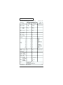
Contents
IMPORTANT NOTES ...............................................................................4
Features ...................................................................................................8
How To Use This Manual........................................................................9
About the Symbols in This Manual .............................................................................................. 9
Panel Descriptions................................................................................10
Front Panel................................................................................................................................................. 10
Rear Panel .................................................................................................................................................. 11
Attaching the HPD-15 to the Stand .....................................................12
Chapter 1 Quick Start ...........................................................................13
Turning On/Off the Power..................................................................................................................... 13
Listening to the Demo Song.................................................................................................................... 14
Performing................................................................................................................................................. 15
Hit the pads.................................................................................................................................... 15
Slide Your Finger on the Ribbons ............................................................................................... 15
Pass Your Hand over the D Beam .............................................................................................. 16
Sustaining the Sound (ROLL/HOLD Button) .......................................................................... 16
Playing Various Sounds ............................................................................................................... 17
Controlling Pad Sounds ............................................................................................................... 17
Playing a Scale ............................................................................................................................... 18
Using Knobs to Modify the Tone (Realtime Modify) .............................................................. 19
Adding Effects Such as Reverb or Distortion (Multi-Effects) ............................................................ 20
Turning Multi-Effects On/Off .................................................................................................... 20
Changing Sounds to Play (Patch Select) ............................................................................................... 21
Changing Patches with the Dial.................................................................................................. 22
Changing Patches with the Panel Switches............................................................................... 22
Changing Patches with the Pads (Pad Patch Select) ................................................................ 23
Changing the Settings of a Patch (EZ Edit) .......................................................................................... 24
Playing Back a Preset Pattern ................................................................................................................. 26
Changing the Tempo .................................................................................................................... 27
System Settings ......................................................................................................................................... 28
Adjusting the Display for Best Visibility (LCD Contrast)....................................................... 28
Adjusting the D Beam Sensitivity............................................................................................... 29
If the Sound or Operation Is not as You Expect................................................................................... 30
Rapidly Selecting Parameters or Values ............................................................................................... 31
Key Repeat Function..................................................................................................................... 31
Turbo Repeat Function................................................................................................................. 31
Skip Function ................................................................................................................................. 32
Try to Play the Conga .............................................................................................................................. 34
Conga - Basic Rhythm .................................................................................................................. 34
Chapter 2 Modifying a Patch................................................................35
Basic procedure in Edit Mode ................................................................................................................ 35
Adjusting Sounds ..................................................................................................................................... 36
Adding Cyclic Change to the Tone........................................................................................................ 38
Effect Settings............................................................................................................................................ 39
Adjusting the Reverb Settings..................................................................................................... 39
Adjusting the Multi-Effect Settings ............................................................................................ 40
Controlling the Tone ................................................................................................................................ 52
Using a Pad to Start a Pattern ................................................................................................................. 54
Set the Volume of the Entire Patch ........................................................................................................ 54
Settings for Other Functions ................................................................................................................... 54
Limiting the Resonance ................................................................................................................ 54
5
Contents
Adjusting the Sensitivity of the Pads ......................................................................................... 54
Specifying the Roll Speed ............................................................................................................ 55
Setting for MIDI Transmission ............................................................................................................... 55
Naming a Patch......................................................................................................................................... 55
Saving Your Settings (Write) .................................................................................................................. 56
Duplicating Settings (Copy).................................................................................................................... 56
Basic Procedure for Copy............................................................................................................. 56
Copying a Pad Set (Pad Set Copy).............................................................................................. 57
Copying Pad/D Beam/Ribbon Settings (Pad Copy)............................................................... 57
Copying Pad/D Beam/Ribbon Settings to All Pads (Pad Copy to All) ............................... 57
Exchanging Patch Settings (Patch Exchange) ........................................................................... 57
Copying a Value to All Pads................................................................................................................... 58
Using Realtime Modify to Adjust Values ............................................................................................. 58
Chapter 3 Recording Your Performance (Sequencer).......................59
Basic Settings for Recording ................................................................................................................... 59
Settings for the Pattern ................................................................................................................. 60
Settings for the Click, and others ................................................................................................ 61
Settings for the Recording (Set in the Recording Stand-by mode) ........................................ 62
Rehearsal Function........................................................................................................................ 62
Basic Settings for Playing Back............................................................................................................... 63
Pause ............................................................................................................................................... 63
Fast-Forward and Rewind ........................................................................................................... 63
Synchronizing with an External MIDI device (MIDI Sync) .................................................... 63
Changing the Settings of Pattern............................................................................................................ 63
Saving the Changed Settings....................................................................................................... 63
Editing a Pattern ....................................................................................................................................... 64
Basic Settings for Editing ............................................................................................................. 64
Copying a Pattern ......................................................................................................................... 64
Erasing Parts .................................................................................................................................. 64
Connecting Two Patterns............................................................................................................. 64
Deleting a Pattern.......................................................................................................................... 64
Chapter 4 Changing Patches in the Desired Sequence ....................65
Creating a Patch Chain (Chain Edit) ..................................................................................................... 65
Specifying the Last Step of the Patch Chain.............................................................................. 65
Inserting a Chain Step .................................................................................................................. 66
Deleting a Chain Step ................................................................................................................... 66
Playing with a Patch Chain (Chain Play).............................................................................................. 66
Chapter 5 Settings for the Entire HPD-15 ...........................................67
Settings for basic operation ..................................................................................................................... 67
Settings for the Basic Operation.................................................................................................. 68
Settings for the Controllers .......................................................................................................... 69
Turning On/Off the D Beam....................................................................................................... 69
Turning On/Off the Ribbons ...................................................................................................... 69
Setting the Pad Sensitivity ........................................................................................................... 70
Using the Foot Switches to Control the Tone / Sequencer ................................................................ 71
Settings for the Foot Switches ..................................................................................................... 71
Using the Pedal to Control the Hi-Hat / Tone..................................................................................... 72
Settings for the Pedal .................................................................................................................... 72
Using the External Pads/Kick Trigger Unit to Trigger a Sound ....................................................... 73
Settings for the External Pads / Kick Trigger Unit .................................................................. 73
More Detailed Settings for the External Pads / Kick Trigger Unit........................................ 74
Setting the Sound of the External Pads / Kick Trigger Unit .................................................. 75
MIDI Settings ............................................................................................................................................ 75
Restoring Settings to Their Default Values (Factory Reset) ............................................................... 75
6
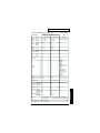
Contents
Chapter 6 Connecting MIDI Devices ...................................................76
Using the HPD-15 to Play External Instruments ................................................................................. 76
Setting for MIDI Transmission.................................................................................................... 76
Setting the MIDI Channels........................................................................................................... 77
Using the HPD-15 As a Sound Module................................................................................................. 78
Setting the MIDI Channel for a Part........................................................................................... 78
Using with the Roland SPD-20 (SOFT THRU)..................................................................................... 79
Using a Sequencer or a Computer to Record/Play Back the Performance on the HPD-15 .......... 79
Cutting the Connection Between the Sound Generator and the Pad Controller
(Local Control)............................................................................................................................... 80
Saving Data to an External MIDI Instrument....................................................................................... 80
Transmitting (Bulk Dump) .......................................................................................................... 80
Receiving (Bulk Load) .................................................................................................................. 81
Setting the Device ID .................................................................................................................... 82
Program Change Number List (User Patches) ......................................................................... 82
Troubleshooting....................................................................................83
Problems With the Overall Sound ......................................................................................................... 83
MIDI-related Problems ............................................................................................................................ 84
Sequencer-related Problems ................................................................................................................... 84
Restoring the Factory Settings............................................................85
Messages and Error Messages ...........................................................86
About MIDI .............................................................................................88
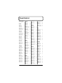
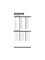
Preset Patch List...................................................................................90
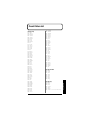
Preset Pattern List ................................................................................91
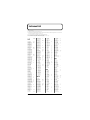
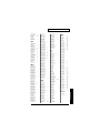
Instrument List ......................................................................................92
Pad Set Instrument List ........................................................................................................................... 94
Backing Instrument List .......................................................................................................................... 94
Effect Type List .....................................................................................95
Demo Song List.....................................................................................96
MIDI Implementation.............................................................................97
Specifications......................................................................................112
Index.....................................................................................................113
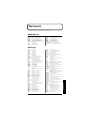
7
Features
• The HPD-15 is a compact and lightweight digital hand percussion unit
with built-in sound generator, that you can play with your naked hands.
• A pressure-sensitive pad divided into fifteen sections allows you to play
full-fledged hand percussion without any other equipment.
• 600 versatile sounds including percussion instruments from around the
world with Latin, African, and Asian sounds, as well as drum sets,
dance sounds, and sound effects.
• Numerous controllers including ribbons, D Beam , and realtime modify
knobs allow you to create realtime changes in the sound.
• Kick trigger units and a hi-hat controller can be connected to create a
space-saving drum set.
• Convenient editing functions for the percussionist include an EZ Edit
function and a Guide tone (click note).
• Built-in high-quality reverb and multi-effects selected especially for
percussion let you produce spacious sounds or invent creative new
possibilities.
• Basic rhythm performances are built-in as preset patterns, so that you
can enjoy ensemble playing or use the HPD-15 to keep time in place of a
metronome.
• A convenience sequencer is provided for recording your performance in
realtime — great for practicing or listening to your own playing.
• The HPD-15 can be connected to an external sound module as a MIDI
controller, or used as to input drum parts for music data.
8
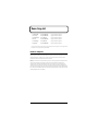
How To Use This Manual
This owner’s manual is organized as follows.
Quick Start (Chapter 1)
This section is intended for those using the HPD-15 for the first time, and
explains how to use various functions in a simple way. Please read Quick
Start and follow along by actually operating the HPD-15. This will help you
understand most of what you need to know for basic operations.
Advanced Use (Chapter 2 – Chapter 6)
This section explains all functions of the HPD-15 and is divided into specific
parts. Basic operations are covered in the Quick Start. The Advanced Use
section assumes you already understand basic procedures, so if anything
unclear, refer to the “Quick Start.”
Chapter 2 Modifying a Patch
This chapter explains how to modify the sounds you play, how to control
the sounds, and how to use effects.
Chapter 3 Recording Your Performance (Sequencer)
This chapter explains how to record and play back your performance.
Chapter 4 Changing Patches in the Desired Sequence
This chapter explains the Patch Chain function that lets you switch patches
in a desired order.
Chapter 5 Settings for the Entire HPD-15
This chapter explains settings that affect the entire HPD-15, such as screen
display, control settings, and how to connect external pads, pedals, or foot
switches for use with the HPD-15.
Chapter 6 Connecting MIDI Devices
This chapter explains MIDI-related functions, such as using the HPD-15 to
play external sound modules, or saving data on an external device.
Appendices
If you run into problems, refer to “Troubleshooting” to make sure that the
settings are correct. If an error message appears during operation, refer to
“Messages and Error Messages” and take appropriate action. This section
also provides information related to MIDI, backing instrument list, and the
MIDI implementation charts.
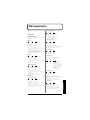
About the Symbols in This Manual
Words of symbols enclosed in [square brackets] indicate panel buttons or dial.
For example, [EDIT] signifies the Edit button.
The explanations in this manual
include illustrations that depict
what should typically be shown
by the display. Note, however,
that your unit may incorporate
a newer, enhanced version of
the system (e.g., includes newer
sounds), so what you actually
see in the display may not
always match what appears in
the manual.
9
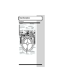
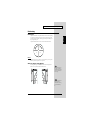
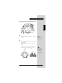
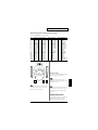
Panel Descriptions
Front Panel
fig.0-01.e
Sequencer Section
VOLUME Knob
You can record and play back
your performance (p. 59).
Adjusts the volume of the entire HPD-15.
When this knob is turned fully counterclockwise,
no sound will be output.
PATCH/VALUE Dial
REALTIME MODIFY Section
Turn these knobs to modify the
sound (p. 19).
Turn to select a patch or change the value.
D BEAM
Pass your hand to produce or
control the sound (p. 16).
Ribbon (L)
Patch Select
Section
Changes the patch (p. 22).
Ribbon (R)
Slide your finger
on this ribbon to
produce a sound
or to control the
tone (p. 15).
PATCH SEL Button
ROLL/HOLD Button
When this button is lit, the sound
will repeat like rolls while pressing
a pad (p. 16).
10
Pad
Strike to produce a
sound or press to
control the tone (p.15).
Striking the pad while holding
down this button changes the
patch (p. 23). This button is
used as the shift button of some
operations, too.
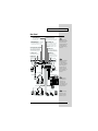
Panel Descriptions
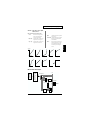
Rear Panel
fig.0-02.e
TRIGGER INPUT Jack
Connect the kick trigger units, external pads,
foot switches (p. 73).
FOOT SWITCH Jack
Connect the optional foot switches (BOSS FS-5U).
You can use foot switches to select a patch, to
control the sequencer, and so on (p. 71).
MIDI Connectors (IN, OUT/THRU)
EXP PEDAL/HH CTRL Jack
Connect an expression pedal (EV-5), a hi-hat
control pedal (FD-7), or a foot switch (p. 72).
MIX IN STEREO Jack
Connect a CD/MD player or use for the
expanded input at the live performance.
The sound that is input to this jack will
be output from the OUTPUT jacks and
PHONES jack.
Connect the MIDI cable when using the
HPD-15 to play external instruments,
using the HPD-15 as a sound module, or
to save/load the setting data (p. 76).
OUTPUT Jacks
To prevent malfunction
and/or damage to speakers
or other devices, always
turn down the volume, and
turn off the power on all
devices before making any
connections.
Connect to external audio devices or
amps. If using monaural sound, plug
the cable into the L (MONO) jack only.
AC Adaptor Jack
PHONES Jack
Connect the include AC adaptor.
Connect stereo headphones.
Even if headphones are connected,
sound will still be output from the
OUTPUT jacks.
POWER Switch
Turns the power on/off.
Stereo headphones
Cord hook
PCS-31 (optional)
To prevent the inadvertent
disruption of power to
your unit (should the plug
be pulled out accidentally),
and to avoid applying
undue stress to the AC
adaptor jack, anchor the
power cord using the cord
hook, as shown in the
illustration.
Audio cable
Speakers with built-in amp, etc.
AC adaptor
L
R
Stereo set, etc.
BOSS FS-5U (optional)
PCS-31 (optional)
Use only the specified
expression pedal (EV-5;
sold separately). By
connecting any other
expression pedals, you risk
causing malfunction and/
or damage to the unit.
CD Player, etc.
d
Rolan
Kick trigger unit, External pad, etc.
EV-5 (optional)
FD-7 (optional)
BOSS FS-5U
(optional)
For details on connecting
MIDI devices, refer to
“Chapter 6 Connecting
MIDI Devices” (p. 76).
11
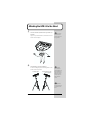
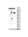
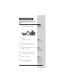
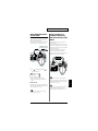
Attaching the HPD-15 to the Stand
1
Attach the stand holder (included with the optional PDS-15) to
the HPD-15.
Using the screws provided with the PDS-15, attach the holder so the unit is
oriented as shown in the diagram.
Use the screws provided
with the PDS-15. Use of
other screws may result in
damage to the unit.
fig.0-03.e
Wide
Narrow
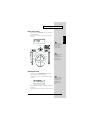
2
Attach the HPD-15 to the pad stand (PDS-15).
For details on assembling the pad stand and attaching the HPD-15, refer to
the owner’s manual for the pad stand.
fig.0-04.e
for playing by fingers
for using the heel of your hand
(like a conga player)
If you attach only the
screws to the HPD-15
without attaching the stand
holder and strike the pads
strongly when it is resting
on the floor or table, the
screw heads may contact
the floor or table and
scratch it.
Do not slope the stand
excessively. Be careful that
the stand does not lose its
balance.
12
Chapter 1 Quick Start
This chapter explains basic operation of the HPD-15.
Chapter 1
For details on modifying sounds and settings, refer to “Chapter 2 Modifying
a Patch” (p. 35).
Turning On/Off the Power
* Once the connections have been completed (p. 11), turn on power to your various
devices in the order specified. By turning on devices in the wrong order, you risk
causing malfunction and/or damage to speakers and other devices.
1
2
Make sure that all volume controls on the HPD-15 and
connected devices are set to “0.”
Turn on the device connected to the MIX IN Jack.
3
Turn on the HPD-15’s [POWER] switch.
4
Turn on the device connected to the OUTPUT Jacks.
5
Adjust the volume levels for the devices.
Before switching off the power, lower the volume on each of the devices in
your system and then TURN OFF the devices in the reverse order to which
they were switched on.
When turns the power on,
be careful not to shut the
window of the D Beam (p.
16) until the patch name (p.
21) is displayed. The HPD15 adjusts the sensitivity of
the D Beam automatically
when turns the power on.
If you connect the hi-hat
control pedal (FD-7,
optional), do not step on
the pedal until the patch
name is displayed when
the power is turned on. The
HPD-15 will check the
position of the pedal then.
This unit is equipped with
a protection circuit. A brief
interval (a few seconds)
after power up is required
before the unit will operate
normally.
13
Chapter 1 Quick Start
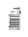
Listening to the Demo Song
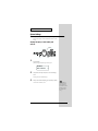
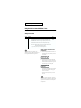
1
Simultaneously press [SEQUENCER] and [SYSTEM].
fig.1-01
fig.1-02
HPD-15 DEMO PLAY
1.TABLECTRIC
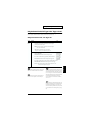
2
Turn [PATCH/VALUE] or use [PATCH NUMBER
] and
[PATCH NUMBER
] to select the demo song that you wish
to hear.
fig.1-03
3
For details on the demo
songs, refer to “Demo Song
List” (p. 96).
Press [PLAY/STOP].
fig.1-04
Playback will begin.
To stop playback, press [PLAY/STOP] once again.
4
Press [EXIT].
You will return to the previous screen.
14
No data for the music that
is played will be output
from MIDI OUT.
Chapter 1 Quick Start
Performing
Hit the pads
Chapter 1
The pads of the HPD-15 will produce different volume or tones depending
on where or how strongly they are struck, and you can also vary the tone
and duration of the sounds by continuing to press the pad after striking it or
by pressing another pad.
The pads are divided into 15 sections, which are numbered as follows.
fig.1-05
B4
B5 C1
C2
B3
B2
C3
A2
A4
B1
C4
C5
A3
A1
A5
Pad Set
The pads are in sets of five. Pads A1–A5 are referred to as pad set A, pads
B1–B5 as pad set B, and pads C1–C5 as pad set C.
Slide Your Finger on the Ribbons
By sliding your finger on the ribbons located at the left and right of the
HPD-15 you can produce sounds or modify the tone.
fig.1-06
If Ribbon [SOUND] is not
lit, sliding your finger on
the ribbon will not produce
sound. Press [SOUND] to
make it light.
[HOLD] is used when you
control the tone by a
ribbon. Refer to “Turning
On/Off the Ribbons” (p.
69).
15
Chapter 1 Quick Start
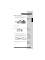
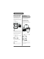
Pass Your Hand over the D Beam
By passing your hand over the D Beam located at the top of the panel, you
can produce sounds or modify the tone.
fig.1-07
Sustaining the Sound (ROLL/HOLD Button)
1
Press [ROLL/HOLD] (located at the upper left of the pads) to
make it light.
If D Beam [SOUND] is not
lit, passing your hand over
the D Beam will not
produce sound. Press
[SOUND] to make it light.
If there is no sound even
though [SOUND] is lit,
adjust the sensitivity of the
D Beam.
If D Beam [CONTROL] is
not lit, passing your hand
over the D Beam will not
modify the tone. Press
[CONTROL] to make it
light.
fig.1-08
Ribbons, D Beam,
connected expression
pedal, and connected hi-hat
control pedal are called
“controller.“
2
Press the pad.
While you press the pad, the sound will be repeated as a roll.
Pressing strongly will increase the volume.
To specify the interval at
which the sound is
repeated, refer to
“Specifying the Roll Speed”
(p. 55).
The sound of the instruments marked with “*H” in the Instrument List (p.
92) will sustain if you remove your hand from the pad.
The sound of the
instrument assigned to the
D Beam, ribbons, external
triggers, or pedal will not
be repeated.
16
Chapter 1 Quick Start
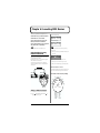
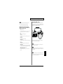
Playing Various Sounds
Let’s use the patch (p. 21) of P0101 Conga to hear various sounds from the
pads, ribbons, and D Beam.
Chapter 1
* If the following screen is not shown, turn [PATCH/VALUE] until the following
screen appears.
fig.1-09
P01 LATIN
01 Conga
If D Beam [SOUND] is not
lit, passing your hand over
the D Beam will not
produce sound. Press
[SOUND] to make it light.
fig.1-10
Bell Tree
Timbale Shaker
(High)
Timbale
(Low)
Bongo
(Low)
Maracas
Tambourine
Claves
Conga
Conga
(Toe/Open) (Low Open)
Bongo
(High)
If [SOUND] located above
the ribbon is not lit,
rubbing the ribbon will not
produce sound. Press
[SOUND] to make it light.
Cowbell
Agogo
Conga
(Bass)
Conga
(Heel/Open)
Conga
(Open/Slap)
Conga
Slide
Guiro
Controlling Pad Sounds
Let’s use the patch (p. 21) of P0201 Talking Drm and use the ribbons, D
Beam, and other pads to control the pitch of the pads.
* If the following screen is not shown, turn [PATCH/VALUE] until the following
screen appears.
fig.1-10a
P02 AFRICAN
01 TalkingDrm
If D Beam [CONTROL] is
not lit, passing your hand
over the D Beam will not
modify the tone. Press
[CONTROL] to make it
light.
While striking the pad, rub the ribbons or move your hand over the D Beam
to raise the pitch.
While striking the pad, press one of the pads A1–A5 will also raise the pitch.
17
Chapter 1 Quick Start
Playing a Scale
You can use the pads to play the sounds of a pitched instrument such a steel
drum or marimba.
Let’s use the patch (p. 21) of P0501 Vibraphone to play a scale.
* If the following screen is not shown, turn [PATCH/VALUE] until the following
screen appears.
fig.1-10b
P05 ORCH
01 Vibraphone
The pads are assigned to the notes of the keyboard as follows.
fig.1-10c
C2
C3
Simultaneously striking
pads A1–A3 (the left half of
pad set A) will produce a
“C” chord, and
simultaneously striking
A3–A5 (the right half) will
produce a “G” chord.
Helpful Use of the Included Label
G
F #
E
D #
F
G #
A
A #
B
D
C #
C
18
C
C #
D
Chapter 1 Quick Start
The sounds of the HPD-15 have various parameters that determine the
loudness, pitch, and duration, and how the notes are sounded. By
modifying the values of each parameters, you can vary the tone.
Normally, you will adjust the parameter values to your liking before you
perform. However, some of the parameters can be freely modified while
you play. This is referred to as “realtime modify.”
In Edit mode (p. 35), you
can also use Realtime
Modify to adjust the
parameter values (p. 58).
fig.1-11
3
1
1
Press [SELECT] to select the parameter that you wish to modify.
The indicator at the right of the selected parameter will light.
2
Sound the pad (D Beam, ribbon) for the sound that you wish to
modify.
* The M-FX DEPTH and LFO parameters will apply in the same way to all pads/
ribbons/D Beam.
3
Turn the [REALTIME MODIFY] knob.
Modify Lock
Hold down [SELECT], and
sound the pad (D Beam,
ribbon). It will be fixed to
the target of modification
and other pads cannot
become to the target. (The
[SELECT] indicator will
blink at this time.)
To unlock, hold down
[SELECT], and press
[EXIT].
The selected parameter and the value being modified will be displayed, and
the sound will change.
fig.1-12
RTM
A1* PITCH
+600
* If the multi-effects (p. 20) is off, turning the [M-FX DEPTH] knob makes no
modification.
When you turn the knobs
too fast, some noise may be
heard from some tones .
* If the LFO Waveform (p. 38) is set to “OFF,” turning the [LFO RATE], [LFO
PITCH] and [LFO FLT/AMP] knobs makes no modification.
4
By repeating steps 1–3 you can create numerous variations in
the sound.
* By pressing [EXIT/MODIFY CLEAR] you can cancel any value changes you made
(Modify Clear).
Hold down [EXIT/
MODIFY CLEAR], and
press [SELECT]. You can
excute Modify Clear and
cancel the Modify Lock at
the same time.
19
Chapter 1
Using Knobs to Modify the Tone (Realtime Modify)
Chapter 1 Quick Start
Adding Effects Such as Reverb or
Distortion (Multi-Effects)
The HPD-15 contains a multi-effect unit that can apply various effects to the
sound.
Turning Multi-Effects On/Off
1
Press [MULTI-EFFECTS].
fig.1-13
When the effect is on, [MULTI-EFFECTS] will light.
The sound will change according to the selected type of effect.
20
For more on multi-effects,
refer to “Adjusting the
Multi-Effect Settings” (p.
40).
Chapter 1 Quick Start
Changing Sounds to Play (Patch Select)
Chapter 1
A patch contains settings for the pads, controllers, and effects. The HPD-15
contains 80 User patches that you can rewrite if desired, and 160 Preset
patches that cannot be rewritten. User patches and preset patches are
organized into 10 patch groups.
Names are assigned to preset patch groups.
• GROUP 1
LATIN
Latin-American Percussion instruments
• GROUP 2
AFRICAN
Percussion instruments of Africa and
other regions
• GROUP 3
INDIAN
Percussion instruments of India and the
Middle East
• GROUP 4
ASIAN
Percussion instruments of Asia
• GROUP 5
ORCH
Orchestral percussion instruments, and
mallet instruments (e.g., xylophone,
marimba)
• GROUP 6
DRUMS
Drum sets
• GROUP 7
DANCE
Sounds for dance music
• GROUP 8
SFX
Sound effects
• GROUP 9
OTHERS
Melody instruments (e.g., bass,
synthesizer), and other sounds
• GROUP 10
LOOPS
Preset patterns are assigned to pads B1–
C5. You can listen and compare the preset
patterns.
Each patch is assigned a name (Patch Name).
The currently selected group number, patch number, and patch name are
displayed in the screen.
fig.1-15.e
Group Number
U: User
P: Preset
Group Name
P01 LATIN
01 Conga
Patch Number
Patch Name
21
Chapter 1 Quick Start
Changing Patches with the Dial
1
Turn [PATCH/VALUE].
The patch will change as shown in the diagram.
fig.1-16
U0101
U0102
U0108
U0201
P1001
P0901
Changing Patches with the Panel Switches
fig.1-17
2
3
1
1
3
Press [USER] or [PRESET] to select either user patches or
preset patches.
The selected button will light.
2
Use [GROUP -] and [GROUP +] to select the patch group.
The indicator of the selected patch group will light.
3
22
Use [PATCH NUMBER
] and [PATCH NUMBER
select the patch number within the patch group.
] to
If you continue holding a
button, the patch groups/
numbers will change
consecutively (p. 31).
Chapter 1 Quick Start
Changing Patches with the Pads (Pad Patch Select)
fig.1-18
1, 2
B5
B4
C2
B3
C3
B2
A2
C4
A4
C5
B1
1
1
2
Chapter 1
C1
2
Hold down [PATCH SEL], and strike a pad B1–C5 to select a
patch group.
Use the panel switches to
change between user
patches and preset patches.
Hold down [PATCH SEL], and strike pad A2 or A4 to select
the patch number.
Striking pad A4 will increase the patch number, and striking A2 will
decrease it.
* Pads B1–C5 correspond to the patch groups, and pads A2 and A4 correspond to
[PATCH NUMBER
] and [PATCH NUMBER
] respectively.
While you continue
holding [PATCH SEL], the
indicator for the selected
patch group and the
indicator beside the pad
(B1–C5) corresponding to
that group will blink.
fig.1-19
GROUP
4
5
6
3
B4
7
9
1
C1
B3
8
2
B5
10
C2
C3
B2
C4
B1
C5
A2
A4
NUMBER
23
Chapter 1 Quick Start
Changing the Settings of a Patch (EZ
Edit)
The process of modifying a patch is called “editing.” The HPD-15 provides
Easy (EZ) Edit mode for making basic settings, and Edit mode for making
settings in more detail. This section explains EZ Edit mode.
fig.1-20
To learn how to make more
detailed settings, refer to
“Chapter 2 Modifying a
Patch” (p. 35).
4
3
1
6
1
Press [EDIT].
[EDIT] will blink, and you will enter EZ Edit mode.
2
3
4
5
6
Strike a pad to select the pad set (p. 25) that you wish to
modify. You can also select the D Beam or ribbons.
Press [
PARAMETER] or [PARAMETER
parameter that you wish to modify.
] to select the
You can make your
selection rapidly by using
the Key Repeat Function (p.
31) or Skip Function (p. 32).
To modify the value, either turn [PATCH/VALUE] or use
[PATCH NUMBER
] and [PATCH NUMBER
].
Repeat steps 2–4 to continue editing.
When you are finished editing, press [EXIT].
You will return to normal Play mode.
24
If you press [EDIT] once
again, [EDIT] will light and
you will be in Edit mode (p.
35).
The settings you edit will
return to the original
values when you switch
patches. If you wish to keep
your changes, refer to
“Saving your settings
(Write) / Duplicating
settings (Copy)” (p. 56).
Chapter 1 Quick Start
fig.1-20a.e
Patch Number
appears if the Value is edited
Edit Target
(Pad Set, Ribbon, D Beam, etc.)
Chapter 1
"A", "B", or "C" appears
when "Pad Set" is selected
U0101A* PAD SET
Pitch
+200cent
Parameter
Value
fig.1-21.e
EZ Edit — Parameter List
PAD SET,
RIBBON L,
RIBBON R,
D BEAM,
PEDAL,
TRIG 1,
TRIG 2
Inst
Selects the instrument for Pad Set A, B, C
(Ribbon, D Beam).
Refer to Pad Set
Instrument List
(p. 94)
Pads can be selected by five sets.
Level
Adjusts the volume.
0 – 127
Pan
Adjusts the pan (localization) of the output sound.
L63 – R63,
Random,
Alternate
Random: The pan changes randomly each time the pad is struck.
Alternate: The pan alternates left and right each time the pad is struck.
ReverbSend
Adjusts the reverb depth.
0 – 127
Pitch
Adjusts the pitch of the sound.
-2400 – +2400
Decay
Adjusts the duration (decay time).
-31 – +31
MULTI-FX/LFO
Turns the multi-effects and LFO on/off.
OFF, ON,
PadData
If you select PadData, this will be determined
by the on/off setting in Edit mode (p. 36).
REVERB
MULTI-FX
PATCH LEV
PATCH NAME
* PadData can be
selected for PAD SET.
Type
Selects the type of the reverb.
Refer to Effect
Type List (p. 95)
Depth
Adjusts the overall reverb depth.
0 – 127
Type
Selects the type of the multi-effects.
Refer to Effect
Type List (p. 95)
Depth
Adjusts the depth of the multi-effects.
0 – 127
FxOut Volume
Adjusts the output volume of the multi-effects.
0 – 127
Fx Rev Send
Adjusts the depth of reverb applied to the
sound processed by the multi-effects.
0 – 127
MasterVolume
Adjusts the volume of the entire patch.
0 – 127
Give the pattern a name of up to 10 characters.
Refer to "Naming
a Patch" (p. 55)
* About PEDAL, TRIG 1, and TRIG 2, see p. 72–p. 73.
25
Chapter 1 Quick Start
Playing Back a Preset Pattern
fig.1-22
2
3, 4
5
1
1, 5
Press [SEQUENCER].
[SEQUENCER] will light, and you will enter Sequencer mode.
fig.1-22a.e
Pattern Number
U: User
P: Preset
Current Measure
Current Beat Tempo
P01 001-01 =100
4/4
Cha-Cha
Time Signature
2
3
Pattern Name
Turn [PATCH/VALUE] to select the pattern.
Press [PLAY/STOP].
The selected pattern will play back.
4
To stop playback, press [PLAY/STOP] once again.
The pattern will stop playing.
5
Press [SEQUENCER] or [EXIT].
You will return to normal Play mode.
26
For more on preset
patterns, refer to “Preset
Pattern List” (p. 91).
Chapter 1 Quick Start
Changing the Tempo
fig.1-23
Chapter 1
2
1, 3
1
Press [TEMPO].
[TEMPO] will light, current tempo is displayed in the screen.
fig.1-23a
Tempo
2
3
=100
Turn [PATCH/VALUE] to change the tempo.
The tempo can be changed
either when the pattern is
playing or stopped.
When you have finished making changes, press [TEMPO]
once again.
[TEMPO] will go dark, and you will return to the previous screen.
27
Chapter 1 Quick Start
System Settings
Settings that are shared by all patches are called “system settings.”
Settings such as the display contrast and the D Beam sensitivity are system
settings.
Adjusting the Display for Best Visibility (LCD
Contrast)
fig.1-24
2
3
1
1, 3
Press [SYSTEM].
[SYSTEM] will light, and the following screen will appear.
fig.1-25
UTILITY
LCD Contrast
2
5
Turn [PATCH/VALUE] to adjust the contrast of the display
screen.
Increasing the value will darken the display.
3
When you have finished adjusting, press [SYSTEM] or [EXIT].
You will return to normal Play mode.
28
When you modify the
system setting, the new
setting is automatically
saved as soon as you make
the change. You do not
have to operate for the
storing.
Chapter 1 Quick Start
Adjusting the D Beam Sensitivity
fig.1-26
The HPD-15 adjusts the
sensitivity of the D Beam
automatically when turns
the power on.
3
2
1
4
1, 4
Press [SYSTEM].
[SYSTEM] will light.
2
Press [PARAMETER
] to display the following screen.
You can make your
selection rapidly by using
the Key Repeat Function (p.
31) or Skip Function (p. 32).
fig.1-27
CONTROLLER
DBEAM Sens
3
100
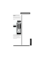
Place your hand about 20 inches (50 cm) above the D Beam,
and turn [PATCH/VALUE] to adjust the sensitivity.
Move the meter at the upper right of the screen to the center line as shown
in right screen. The D Beam will respond as far as the position where your
hand was when you made the adjustment.
fig.1-28
CONTROLLER
DBEAM Sens
4
100
CONTROLLER
DBEAM Sens
64
The sensitivity of the D
Beam will be less in a dark
location. In such locations,
it is a good idea to make
the adjustment with your
hand approximately 12
inches (30 cm) above the D
Beam.
When you have finished adjusting, press [SYSTEM] or [EXIT].
You will return to normal Play mode.
For details on other system
parameters, refer to
“Chapter 5 Settings for the
entire HPD-15” (p. 67).
29
Chapter 1
The sensitivity of the D Beam will change depending on the amount of light
in the vicinity of the unit. If it does not function as you expect, adjust the
sensitivity as appropriate for the brightness of your location.
Chapter 1 Quick Start
If the Sound or Operation Is not as You
Expect
If, as you modify the settings, the sound or operation is no longer as you
expect and you are unable to restore the correct settings, you can execute the
Factory Reset operation to reset all settings to their factory condition.
fig.1-29
When you execute factory
reset, the edited contents
will be lost.
4, 5
1
2
3
1
Press [SYSTEM].
[SYSTEM] will light.
2
Hold down [PARAMETER
] to access the following screen.
fig.1-30
FACTORY RESET
SYSTEM
[WRITE]
3
Turn [PATCH/VALUE] to select “ALL.”
fig.1-30a
FACTORY RESET
ALL
[WRITE]
4
Press [WRITE].
The following screen will appear.
fig.1-31
Are You Sure?
[WRITE/EXIT]
5
If you wish to execute factory reset, press [WRITE].
After the data has been initialized, the following screen will appear.
fig.1-09
P01 LATIN
01 Conga
* If you decide not to execute, press [EXIT].
30
You can make your
selection rapidly by using
the Skip function (p. 32).
It is also possible to
initialize specific data, such
as only the patches or only
the system settings. For
details, refer to “Restoring
the Factory Settings” (p.
85).
Chapter 1 Quick Start
Rapidly Selecting Parameters or Values
Key Repeat Function
1
Chapter 1
This can also be used when selecting either parameters or values, and when
selecting patch groups or patch numbers.
Press and hold either [
PARAMETER],
[PARAMETER
], [PATCH NUMBER
], [PATCH
NUMBER
], [GROUP -], or [GROUP +].
The parameter, value, patch number, or group will change consecutively.
Turbo Repeat Function
This function can also be used when selecting a value or patch number.
1
Hold down [PATCH NUMBER
[PATCH NUMBER
].
], and press
fig.1-32.e
press
When you select the
instrument or adjust the
pitch, you can use the Skip
function (p. 32) instead of
the Turbo repeat function.
while holding down
The value (value or patch number) will increase rapidly.
1
Hold down [PATCH NUMBER
[PATCH NUMBER
].
], and press
fig.1-33.e
while holding down
press
The value (value or patch number) will decrease rapidly.
Turbo Function of the Dial
1
Hold down [PATCH SEL], and turn [PATCH/VALUE].
fig.1-33a.e
while
holding
down
turn
If you are changing the value, the value will change in 10 steps.
31
Chapter 1 Quick Start
Skip Function
You can rapidly select parameters or values.
Skipping Parameters
Parameters are grouped into several categories according to the content
that is being edited. By using the skip function you can jump to the first
parameter of the category.
1
Hold down [PARAMETER
[
PARAMETER].
], and press and release
fig.1-34.e
while holding down
press and release
UTILITY
LCD Contrast
5
CONTROLLER
DBEAM Sens
100
The first parameter of the next category will be shown.
1
Hold down [
PARAMETER], and press and release
[PARAMETER
].
fig.1-35.e
while holding down
press and release
CONTROLLER
DBEAM Sens
100
UTILITY
LCD Contrast
The first parameter of the previous category will be shown.
32
5
Chapter 1 Quick Start
Skipping Values
When selecting an instrument or setting the pitch, you can make the value
jump.
Chapter 1
Instruments (sounds) are grouped into several categories. By using the skip
function you can jump to the first sound in each group.
The pitch value can be changed in steps of 100 cent (one semitone).
1
While pressing [PATCH NUMBER
[PATCH NUMBER
].
], press and release
fig.1-36.e
press and
release
while holding down
Pad Inst (p. 36) select screen
P0101A1*PAD INST
L09:Conga Hi /H
P0101A1*PAD INST
F01:Shekere
Pitch adjust screen
P0101A1*PAD INST
Pitch
+12cent
P0101A1*PAD INST
Pitch
+100cent
If you are selecting instruments, the first sound in the next group will be
displayed.
If you are setting the pitch, the value will increase in 100 cent steps.
1
While pressing [PATCH NUMBER
[PATCH NUMBER
].
], press and release
fig.1-37.e
while holding
down
press and release
Pad Inst (p. 36) select screen
P0101A1*PAD INST
R01:Dry Hard Kik
P0101A1*PAD INST
O01:Sleigh Bell
Pitch adjust screen
P0101A1*PAD INST
Pitch
+783cent
P0101A1*PAD INST
Pitch
+700cent
If you are selecting instruments, the first sound in the previous group will
be displayed.
If you are setting the pitch, the value will decrease in 100 cent steps.
33
Chapter 1 Quick Start
Try to Play the Conga
Let’s try to play the conga using the HPD-15.
Use the patch P0101 Conga.
• Open (O)
Strike the pad A5 or A4, and remove the hand immediately.
• Closed 1 (C1)
Strike the pad A5 and do not remove the hand.
• Closed 2 (C2)
While pressing the pad A1 by the left hand, strike the pad A5.
• Open Slap (OS)
Strike the edge of the pad A5 powerfully and remove the hand
immediately.
• Closed Slap (CS)
While pressing the pad A1 by the left hand, strike the edge of the pad
A5.
• Heel (H)
Strike the pad A1 by the heel of the left hand.
• Toe (T)
While pressing the PAD A1 by the heel of the left hand, strike the pad
A2 by the toe of the same hand.
• Pitch Bend (PB)
While pressing the pad A3, strike the pad A5.
Conga - Basic Rhythm
fig.1-38.e
Pad:
A1 A2 A5 A2 A1 A2 A4 A4
T CS T H T O O
Technique: H
A1 A2 A5 A2 A1 A2 A4 A4
H T CS T H T O O
x
L
L R L
x
L
L R R
L
L R L
L
L R R
A2
A4
A3
Pad:
A1 A2 A5 A4 A4 A2 A5 A5
Technique: H T CS O O T O O
A1 A2 A5 A4 A4 A2 A5 A5
H T CS O O T O O
x
L
L R R R L R R
L: left hand
R: right hand
34
x
L
L R R R L R R
A1
A5
Chapter 2 Modifying a Patch
This chapter explains Edit mode, where you can make
detailed settings.
Basic procedure in Edit Mode
5. To modify the value, either turn [PATCH/VALUE] or
1. Press [EDIT] to make it blink; you will enter EZ Edit
mode.
fig.2-01
use [PATCH NUMBER
] and [PATCH NUMBER
].
fig.2-05.e
2. Once again press [EDIT] to make it light; you will enter
Edit mode.
* The parameter category will be displayed in the upper
right of the screen.
U0101A3 PAD INST
Pad Level
100
Value
6. Repeat steps 3–5 to continue editing.
7. When you are finished editing, press [EXIT] or [EDIT].
fig.2-02.e
Parameter Category
[EDIT] will go dark, and you will return to normal Play
mode.
U0101A1 PAD INST
L09:Conga Hi /H
fig.2-06
3. Strike a pad to select the pad (D Beam, ribbon) that you
wish to edit.
U01 USER01
01* Conga
fig.2-03.e
Pad A3 is selected
You can make your selection rapidly (p. 31). You can also use
realtime modify to change the value (p. 58).
U0101A3 PAD INST
L17:Conga HiBass
D Beam is selected
The settings you edit will return to the original values when
you switch patches. If you wish to keep your changes, refer
to “Saving Your Settings (Write) / Duplicating Settings
(Copy)” (p. 56).
U0101DB PAD INST
I35:Bell Tree
Ribbon (right) is selected
U0101RR PAD INST
L18:Conga Slide
4. Press [
PARAMETER] or [PARAMETER
select the parameter that you wish to modify.
fig.2-04.e
If you edit the settings of a user patch, you can keep your
changes in the same patch by pressing [WRITE] twice.
] to
When you change a value, an “*” will appear beside the
patch number in the screen, indicating that the data is being
edited. If you switch patches or perform the Write or Copy
operation (p. 56), the “*” will disappear.
U0101A3 PAD INST
Pad Level
100
Parameter
35
Chapter 2
U0101A
PAD SET
001:Conga
Chapter 2 Modifying a Patch
Adjusting Sounds
Sweep: -31–+31
Changes the pitch.
Select the sound that you wish to play by using the pads, D
Beam, or ribbons. You can also adjust the pitch or duration of
the sound.
* Some parameters have relation to the parameters in EZ Edit
mode. If there are problems (e.g., no sound), check the
parameters in EZ Edit mode.
Parameter Category: PAD INST
fig.2-07.e
(Inst select screen)
U0101A1 PAD INST
L09:Conga Hi /H
Inst Group
Inst Name
Positive (+) values will cause the pitch to change from high
to low. Negative (-) values will cause the pitch to change
from low to high.
MULTI-FX/LFO: OFF, ON
Turns the multi-effects and LFO on or off.
TrigMode: Shot, Gate, Trig (Pad)
Move, MovGate, Touch, TchGate,
Scrape, Scrp1wy (D Beam, Ribbon)
Selects how the sound will be played.
• Pad
Shot * :
When you strike the pad, the sound will
play for the duration specified for that
particular sound.
Gate * :
The sound will play while you continue
pressing the pad. This is effective when
you have selected a sustaining sound.
Trig:
The sound will play when you strike the
pad, and will stop when you strike the pad
once again. This is effective when you have
selected a sustaining sound.
(Other value select screen)
U0101A1 PAD INST
Pad Level
100
Parameter
Value
(Inst) : Refer to Instrument List (p. 92)
Selects the sound (instrument.)
* You can jump to the first sound in each instrument group by
using the Skip function (p. 33).
• D Beam, Ribbon
Move:
The sound will play when you place your
hand above (or touch with your finger) and
move.
MovGate:
The sound will play when you place your
hand above (or touch with your finger) and
move. If a sustaining sound is selected, the
sound will continue playing until you stop
your hand or finger.
Touch:
The sound will play when you place your
hand above (or touch with your finger).
TchGate:
The sound will play when you place your
hand above (or touch with your finger). If a
sustaining sound is selected, it will
continue playing until you move your
hand or finger away.
Scrape * :
The sound will play when you move your
hand or finger. This is used to play sounds
such as guiro.
Pad Level: 0–127
Adjusts the volume.
Pan: L63–Center–R63, Random, Alternate
Adjusts the pan (localization) of the output sound.
Random:
The pan changes randomly each time the pad is struck.
Alternate:
The pan alternates left and right each time the pad is
struck.
Reverb Send: 0–127
Adjusts the depth of the reverberation.
Pitch: -2400–+2400cent
Adjusts the pitch.
100 cents is a semitone.
* You can change the pitch in steps of 100 cent by using the Skip
function (p. 33).
Decay: -31–+31
Adjusts the duration (decay time.)
* Some sounds do not change the duration.
Color: -31–+31
Adjusts the tone.
36
• only D Beam
Scrp1wy * : The sound will play continuously when
you move your hand. The sound will play
for only one direction.
* Pedal can be specified the value marked with “*.”
Chapter 2 Modifying a Patch
VeloCurve:
Linear, Exp1–2, Log1–2, Spline,
Loud1–2, Fix1–16
Selects how striking force will affect the volume.
This is the normal setting and most
natural correspondence between
velocity and volume change.
Exp1, Exp2:
Compared to Linear, a wider volume
change will occur for stronger hits.
Log1, Log2:
Compared to Linear, a wider volume
change will occur for softer hits.
Variation in striking force will produce
extreme change.
Spline:
Loud1, Loud2: Variation in striking force will produce
little change, and a constant volume
will be maintained.
The sound will play at a fixed volume
regardless of how strongly you strike.
Fix1 will produce the lowest volume,
and Fix16 will produce the highest
volume.
Fix1–16:
fig.2-08.e
Loudness
Striking force
Linear
Exp1
Exp2
Log1
Log2
Spline
Loud1
Loud2
Fix1
Fix16
Edit Parameters Block Diagram
fig.2-09.e
Pad
D Beam
Ribbon
TrigMode
VeloCurve
Sound
Generator
Inst
Pad Level
Pitch
Decay
Color
Sweep
Pan
L R
MULTI-FX/LFO
Reverb Send
+
+
REVERB
MasterVolume
Fx Rev Send
OUTPUT
FxOut Volume
+
MULTIEFFECTS
37
Chapter 2
Linear:
Chapter 2 Modifying a Patch
Adding Cyclic Change to the
Tone
You can use the LFO (Low Frequency Oscillator) to cyclically
change the pitch, volume, etc.
Realtime2: PITCH, EFFECT
Selects the LFO parameter which is modified by turning the
middle realtime modify knob. You can modify the
PitchDepth if you select the PITCH, or the EffectDepth if you
select the EFFECT.
* The LFO will apply to all pads / D Beam / ribbons.
Parameter Category: PAD LFO
This parameter is effective only when the bottom indicator
that at the upper right of the Realtime Modify knobs is lit by
pressing [SELECT].
fig.2-10
U0101
LFO
Waveform Triangl
Realtime3: FILTER, AMP
Waveform: OFF, Triangl, Sine, SawRise,
SawFall, Square, Trape, Smp&Hld,
Random, Chaos
Selects the waveform of the LFO. If you select OFF, there will
be no change, and the following parameters will not be
displayed.
fig.2-11.e
Triangl
Sine
SawRise
Triangle wave
Sine wave
Sawtooth
wave (Up)
SawFall
Square
Trape
Sawtooth
wave (Down)
Square wave
Trapezoidal wave
Smp&Hld
Random
Chaos
Sample and
hold wave
Random wave
Chaos wave
Rate: 0–127
Adjusts the modulation rate of the LFO waveform.
PitchDepth: 0–127
Adjusts the depth of the pitch modulation.
FilterDepth: 0–127
Adjusts the depth of the modulation in tone.
AmpDepth: 0–127
Adjusts the depth of the modulation in volume.
EffectDepth: 0–127
Adjusts the depth of modulation for the effect parameter. For
details on the parameter that will be modulated, refer to
“Adjusting Multi-Effect Settings” (p. 40).
38
Selects the LFO parameter which is modified by turning the
right realtime modify knob. You can modify the FilterDepth
if you select the FILTER, or the AmpDepth if you select the
AMP.
This parameter is effective only when the bottom indicator
that at the upper right of the Realtime Modify knobs is lit by
pressing [SELECT].
Chapter 2 Modifying a Patch
Effect Settings
You can add reverberation to the sound to create the
sensation of playing in a hall or on stage, apply distortion to
the sound, or add depth, spaciousness, and modulation.
HF Damp: 200Hz–8kHz, THRU
Adjusts the currently at which the high range of the
reverberation will be cut. As you lower the frequency, more
of the high range will be cut, producing a softer sound. If you
do not wish to cut the high range, set this to THRU.
* The effect will apply to all pads / D Beam / ribbons.
Reverb adds reverberation to the sound to simulate a
spacious ambience.
Parameter Category: REVERB
Dly Feedback: 0–127
Adjusts the number of times that the delay sound will be
repeated.
* This will be displayed only if Algo is Delay or PanDly.
fig.2-13.e
Chapter 2
Adjusting the Reverb Settings
fig.2-12
U0101 REVERB/DLY
Type#
Room1
Type: Refer to REVERB/DELAY Type (p. 95)
Algo: Room1–2, Stage, Plate, Hall1–2
Direct Sound
Level
Reverb Sound
Selects the preset setting of reverb.
If you wish to make even more detailed settings, adjust the
algorithm and parameters below. When you change a value,
a “#” will appear beside the “Type.”
Time
Algo: Delay, PanDly
Direct Sound
Delay Sound
Algo: OFF, Room1–2, Stage, Plate, Hall1–2,
Delay, PanDly
Selects the type (algorithm) of reverb. If you select OFF no
reverb will be applied, and the following parameters will not
be displayed.
Level
Time
Dly Feedback
Room1: Simulation of the reverberation in a room
Room2: Brighter reverb than Room1
Stage:
Simulation of on-stage reverberation
Plate:
Simulation of a metal plate reverb
Hall1:
Simulation of a larger space than Room
Hall2:
Brighter reverb than Hall1
Delay:
Standard delay (Echo)
If you change the “Type,” the algorithm of the reverb and the
values of the parameters will be changed to the setting of
each type.
PanDly: Delay that pans (moves) the reflection between
left and right
Level: 0–127
Adjusts the volume of the reverberation (or delay sound).
Time: 0–127
If Algo is Room1–Hall2, this adjusts the duration of the
reverberation. If Algo is Delay or PanDly, this adjusts the
delay time.
39
Chapter 2 Modifying a Patch
Adjusting the Multi-Effect Settings
Multi-effect (M-FX) allows you to select different algorithms
to obtain a variety of effects.
Parameter Category: MULTI-FX
StereoDelay:
Stereo Delay (Delay the sound)
Mod Delay:
Modulation Delay (Delay the sound while
modulating it)
TimeCtrlDly:
Time Control Delay (Control the delay and
pitch in realtime)
3TapDlySht:
3-tap delay short (Delay the sound in three
directions)
3TapDlyLng:
3-tap delay Long
4TapDlySht:
4-tap delay short (Produce four delayed
sounds)
4TapDlyLng:
4-tap delay Long
AdvanceRev:
Advanced Reverb (Add reverb to the sound)
GateReverb:
Gate Reverb (Sharply cut the reverberation)
fig.2-14
U0101
Type#
MULTI-FX
Hall"A"
Type: Refer to MULTI-FX Type (p. 95)
Selects the preset setting of multi-effects.
If you wish to make even more detailed settings, adjust the
algorithm below and parameters on the following pages.
When you change a value, a “#” will appear beside the
“Type.”
The parameters of each algorithm are explained on the
following pages.
Algo:
Selects the algorithm of the effect. The parameters and values
will differ depending on the algorithm.
Stereo EQ:
Stereo Equalizer (Modify the tone)
CompLimiter:
Compressor/Limiter (Make the volume
more consistent)
Enhancer:
Enhancer (Add sparkle to the sound)
Spectrum:
Spectrum (Add character to the sound)
Isolator:
Isolator (Cut off a specific frequency range)
DynamicFltr:
Dynamic Filter (Modify the tone according
to the volume)
Sustainer:
Sustainer (Increase the duration of the sound)
Overdrive:
Overdrive (Mildly distort the sound)
Distortion:
Distortion (Severely distort the sound)
Lo-Fi:
Lo-Fi (Simulate a “low-fidelity” sound)
RingModltr:
Ring Modulator (Give the sound a metallic
character)
Stereo Cho:
Stereo Chorus (Add depth and
spaciousness to the sound)
TetraChorus:
Tetra Chorus (Layer chorus sounds to
create more spaciousness)
Tremolo Cho:
Tremolo Chorus (Cyclically modulate the
volume to create spaciousness)
Space D:
Space D (Add transparent spaciousness)
Stereo Fln:
Stereo Flanger (Add metallic resonance to
the sound)
StepFlanger:
Step Flanger (Add metallic resonance
while shifting the pitch by steps)
Phaser:
Phaser (Give the sound a “swooshing”
character)
FbackPitch:
Feedback Pitch Shifter (Shift the pitch)
40
In the explanation on the following pages, the value of
parameters marked with “RTM” can be controlled by [M-FX
DEPTH] of the Realtime Modify (p. 19).
* If you modify the MULTI-FX DEPTH in EZ Edit Mode (p.
25), the value of these parameters will be changed.
In the explanation on the following pages, the value of
parameters marked with “LFO” can be controlled by the
LFO. For details, refer to “Adding Cyclic Change to the
Tone” (p. 38).
In the explanation on the following pages, the value of
parameters marked by “Ctrl1, Ctrl2, Ctrl3” can be controlled by
the pads, D Beam, and ribbons. For details, refer to the section
on CtrlTx: MFX Ctrl 1–3 in “Controlling the tone” (p. 52).
FxOut Volume:
Adjusts output volume of the multi-effects.
Fx Rev Send:
Adjusts the depth of reverb applied to the sound processed
by the multi-effects.
If you change the “Type,” the algorithm of the effect and the
values of the parameters will be changed to the setting of
each type.
Chapter 2 Modifying a Patch
Stereo Equalizer (Stereo EQ)
Compressor/Limiter (CompLimiter)
This is a four-band stereo equalizer (low, mid x 2, high).
The Compressor/Limiter compresses signals that exceed a
specified volume level, smoothing out unevenness in volume
and preventing distortion from occurring.
Low Freq: 100Hz, 200Hz, 400Hz
Low EQ: -15–+15dB
Threshold: 0–127
Adjusts the level of the low frequency.
Adjusts the volume at which compression will begin.
Mid1Freq: 100Hz–12.5kHz Ctrl3
Ratio: 1:1–100:1, infinite:1 LFO, Ctrl1
Adjusts the frequency of mid range 1.
Adjusts the compression ratio.
Mid 1 Q: 0.5, 1.0, 2.0, 4.0, 8.0
Attack: 0–127 Ctrl2
Adjusts the width of the area around the Mid1Freq that will
be affected by the Level setting. Higher values of Q will
result in a narrower area being affected.
Adjusts the attack time of an input sound.
fig.2-15.e
Level
Chapter 2
Selects the frequency of the low range.
Release: 0–127 Ctrl3
Adjusts the time from when the volume falls below the
Threshold Level until compression is no longer applied.
Pan: L63–Center–R63
Adjusts the stereo location of the output sound.
8.0
0.5
TotalLevel: -15–+15dB RTM
Frequency
Adjusts the output level.
Mid 1 EQ: -15–+15dB LFO, Ctrl1
Adjusts the level for the area specified by the Mid1Freq and
Q settings.
Mid2Freq: 100Hz–12.5kHz
Adjusts the frequency of mid range 2.
Mid 2 Q: 0.5, 1.0, 2.0, 4.0, 8.0
Adjusts the width of the area around the Mid2Freq that will
be affected by the Level setting. Higher values of Q will
result in a narrower area being affected.
Mid 2 EQ: -15–+15dB Ctrl2
Adjusts the level for the area specified by the Mid2Freq and
Q settings.
HighFreq: 4kHz, 8kHz, 12.5kHz
Selects the frequency of the high range.
High EQ: -15–+15dB
Adjusts the level of the high frequency.
TotalLevel: -15–+15dB RTM
Adjusts the output level.
41
Chapter 2 Modifying a Patch
Enhancer
Isolator
The Enhancer controls the overtone structure of the high
frequencies, adding sparkle and tightness to the sound.
The Isolator is a stronger version of an equalizer, and is able
to completely cut a specific frequency range.
Sens: 0–127 LFO, Ctrl1
Low Level: 0–127 Ctrl3
Adjusts the sensitivity of the enhancer.
Adjusts the level of the low frequency.
Mix: 0–127 RTM, Ctrl2
Mid Level: 0–127 LFO, Ctrl1
Adjusts the ratio with which the overtones generated by the
enhancer are combined with the direct sound.
Adjusts the level of the middle frequency.
Low EQ: -15–+15dB
Adjusts the level of the high frequency.
Adjusts the level of the low frequency range.
Pan: L63–Center–R63
High EQ: -15–+15dB Ctrl3
Adjusts the stereo location of the output sound.
Adjusts the level of the high frequency range.
TotalLevel: -15–+15dB RTM
High Level: 0–127 Ctrl2
Adjusts the output level.
Spectrum
Spectrum is a type of filter which modifies the timbre by
boosting or cutting the level at specific frequencies. It is
similar to an equalizer, but has 5 frequency points fixed at
locations most suitable for adding character to the sound.
Dynamic Filter (DynamicFltr)
The Dynamic Filter varies the tone by moving a filter
according to the volume.
Filter Type: LPF, BPF
Band 1: -15–+15dB
Adjusts the 500 Hz level.
Band 2: -15–+15dB LFO, Ctrl1
Adjusts the 1 kHz level.
Band 3: -15–+15dB
Selects the type of filter.
LPF: The wah effect will be applied over a wide
frequency range.
BPF: The wah effect will be applied over a narrow
frequency range.
Adjusts the 1.25 kHz level.
Sens: 0–127 Ctrl2
Band 4: -15–+15dB Ctrl2
Adjusts the sensitivity with which the filter is controlled.
Adjusts the 3.15 kHz level.
Manual: 0–127 RTM, LFO, Ctrl1
Band 5: -15–+15dB
Adjusts the center frequency from which the effect is applied.
Adjusts the 4 kHz level.
Peak: 0–127 Ctrl3
Width: 1–5 Ctrl3
Adjusts the amount of the wah effect that will occur in the
area of the center frequency. Lower settings will cause the
effect to be applied in a broad area around the center
frequency. Higher settings will cause the effect to be applied
in a more narrow range.
Simultaneously adjusts the width of the adjusted areas for all
the frequency bands.
Pan: L63–Center–R63
Adjusts the stereo location of the output sound.
TotalLevel: -15–+15dB RTM
Pan: L63–Center–R63
Adjusts the output level.
Adjusts the stereo location of the output sound.
42
Chapter 2 Modifying a Patch
Overdrive
The Sustainer restrains loud levels and boosts low levels,
making the sound more consistent and sustaining the sound.
This effect creates a soft distortion similar to that produced
by vacuum tube amplifiers.
Attack: 0–127 LFO, Ctrl1
Drive: 0–127 RTM, LFO, Ctrl1
Adjusts the attack time of an input sound.
Sustain: 0–127 Ctrl2
Adjusts the degree of distortion. The volume will change
together with the degree of distortion.
Adjusts the degree of boost.
Character: 1–4
Pan: L63–Center–R63 Ctrl3
Adjusts the stereo location of the output sound.
Selects the character of distortion. Increasing the value will
make more sound pressure.
TotalLevel: -15–+15dB RTM
Pan: L63–Center–R63 Ctrl2
Adjusts the output level.
Adjusts the stereo location of the output sound.
Chapter 2
Sustainer
Distortion
This effect produces a more intense distortion than
Overdrive.
Drive: 0–127 RTM, LFO, Ctrl1
Adjusts the degree of distortion. The volume will change
together with the degree of distortion.
Character: 1–4
Selects the character of distortion. Increasing the value will
make more sound pressure.
Pan: L63–Center–R63 Ctrl2
Adjusts the stereo location of the output sound.
43
Chapter 2 Modifying a Patch
Lo-Fi
Stereo Chorus (Stereo Cho)
This effect intentionally degrades the audio quality to
simulate a Lo-Fi sound.
This is a stereo chorus. A filter is provided so that you can
adjust the timbre of the chorus sound.
Bit Down: 0–7 Ctrl3
PreDelay: 0.0–100ms
Lowers the audio quality. The audio quality will worsen as
this setting is increased.
Adjusts the time delay from when the direct sound begins
until the processed sound is heard.
S-Rate Down: 32, 16, 8, 4 Ctrl2
Rate: 0.05–10.0Hz LFO, Ctrl1
Coarsens the output signal. The sound will become coarser
as this setting is lowered.
Adjusts the rate of modulation.
Low EQ: -15–+15dB
Adjusts the depth of modulation.
Adjusts the level of the low frequency.
Phase: 0–180deg
High EQ: -15–+15dB RTM, LFO, Ctrl1
Adjusts the spatial spread of the sound.
Adjusts the level of the high frequency.
Filter Type: OFF, LPF, HPF
Output: Mono, Stereo
Selects the type of filter.
Specifies how the sound will be output. With a setting of
“Mono,” the output sound will be monaural.
Depth: 0–127 Ctrl2
OFF: A filter will not be used. Cutoff will not be
displayed.
LPF: Cut the frequency range above the cutoff
frequency.
Ring Modulator (RingModltr)
A ring modulator add the amplitude modulation to the
sound, giving a metallic character.
HPF: Cut the frequency range below the cutoff
frequency.
Cutoff: 200–8kHz Ctrl3
Adjusts the basic frequency of the filter.
Frequency: 0–127 Ctrl1
Effect Level: 0–127 RTM
Adjusts the frequency for modulation.
Adjusts the output level of chorus sound.
Character: 0–127 LFO, Ctrl2
Direct Level: 0–127
Adjusts the tone. The high-frequency range will change.
Adjusts the output level of direct sound.
Effect Level: 0–127 RTM, Ctrl3
Adjusts the output level of effect sound.
Direct Level: 0–127
Adjusts the output level of direct sound.
44
Chapter 2 Modifying a Patch
Tetra Chorus (TetraChorus)
Tremolo Chorus (Tremolo Cho)
Tetra chorus uses a four-phase chorus (four layers of
chorused sound) to give richness and spatial spread to the
sound.
Tremolo Chorus is a chorus effect with added Tremolo
(cyclic modulation of volume).
PreDelay: 0.0–100ms
Adjusts the time delay from when the direct sound begins
until the chorus sound is heard.
Adjusts the time delay from when the direct sound begins
until the chorus sound is heard.
Cho Rate: 0.05–10.0Hz LFO
Rate: 0.05–10.0Hz LFO, Ctrl1
Adjusts the modulation speed of the chorus effect.
Adjusts the rate of modulation.
Cho Depth: 0–127
Depth: 0–127 Ctrl2
Adjusts the modulation depth of the chorus effect.
Adjusts the depth of modulation.
Trm Phase: 0–180deg Ctrl3
Pre Delay Dev: 0–20
Adjusts the spread of the tremolo effect.
Adjusts the differences in Pre Delay between each chorus
sound.
Trm Rate: 0.05–10.0Hz Ctrl1
Depth Dev: -20–+20
Trm Depth: 0–127 Ctrl2
Adjusts the difference in modulation depth between each
chorus sound.
Adjusts the modulation depth of the tremolo effect.
Pan Deviation: 0–20 Ctrl3
Adjusts the difference in stereo location between each chorus
sound. With a setting of 0, all chorus sounds will be in the
center. Increasing the value will cause the chorus sound to be
panned more expansively.
Chapter 2
PreDelay: 0.0–100ms
Adjusts the modulation speed of the tremolo effect.
Effect Level: 0–127 RTM
Adjusts the output level of tremolo chorus sound.
Direct Level: 0–127
Adjusts the output level of direct sound.
Effect Level: 0–127 RTM
Adjusts the output level of chorus sound.
Direct Level: 0–127
Adjusts the output level of direct sound.
45
Chapter 2 Modifying a Patch
Space D
Stereo Flanger (Stereo Fln)
Space D is a multiple chorus that applies two-phase
modulation in stereo. This is a chorus with a transparent
character and minimal sense of modulation.
PreDelay: 0.0–100ms
This is a stereo flanger. (The LFO has the same phase for left
and right.) It produces a metallic resonance that rises and
falls like a jet airplane taking off or landing. A filter is
provided so that you can adjust the timbre of the flanged
sound.
Adjusts the time delay from when the direct sound begins
until the processed sound is heard.
PreDelay: 0.0–100ms
Adjusts the rate of modulation.
Adjusts the time delay from when the direct sound begins
until the flanger sound is heard.
Depth: 0–127 Ctrl2
Rate: 0.05–10.0Hz LFO, Ctrl1
Adjusts the depth of modulation.
Adjusts the rate of modulation.
Phase: 0–180deg Ctrl3
Depth: 0–127 Ctrl2
Adjusts the spatial spread of the sound.
Adjusts the depth of modulation.
Tone: -15–+15
Feedback: -98–+98% Ctrl3
Adjusts the tone quality. Positive (+) settings will emphasize
the high range, and negative (-) settings will emphasize the
low range.
Adjusts the amount (%) of the processed sound that is
returned (fed back) into the input. Positive (+) settings will
return the sound in phase, and negative (-) settings will
return the sound in reverse phase.
Rate: 0.05–10.0Hz LFO, Ctrl1
Effect Level: 0–127 RTM
Adjusts the output level of chorus sound.
Direct Level: 0–127
Adjusts the output level of direct sound.
Phase: 0–180deg
Adjusts the spatial spread of the sound.
Filter Type: OFF, LPF, HPF
Selects the type of filter.
OFF: A filter will not be used. Cutoff will not be
displayed.
LPF: Cut the frequency range above the cutoff
frequency.
HPF: Cut the frequency range below the cutoff
frequency.
Cutoff: 200–8kHz
Adjusts the basic frequency of the filter.
Effect Level: 0–127 RTM
Adjusts the output level of flanger sound.
Direct Level: 0–127
Adjusts the output level of direct sound.
46
Chapter 2 Modifying a Patch
Step Flanger (StepFlanger)
Phaser
The Step Flanger effect is a flanger in which the flanger pitch
changes in steps. The speed at which the pitch changes can
also be specified in terms of a note-value of a specified
tempo.
A phaser adds a phase-shifted sound to the original sound,
producing a twisting modulation that creates spaciousness
and depth.
Manual: 100–8kHz
Adjusts the time delay from when the direct sound begins
until the flanger sound is heard.
Adjusts the basic frequency from which the sound will be
modulated.
Rate: 0.05–10.0Hz LFO, Ctrl3
Rate: 0.05–10.0Hz Ctrl3
Adjusts the frequency (period) of modulation.
Adjusts the rate of modulation.
Depth: 0–127 Ctrl2
Depth: 0–127 Ctrl2
Adjusts the depth of modulation.
Adjusts the depth of modulation.
Resonance: 0–127 Ctrl1
Feedback: -98–+98%
Adjusts the amount of feedback for the phaser.
Adjusts the amount (%) of the flanger sound that is returned
(fed back) into the input. Negative (-) settings will invert the
phase.
Mix: 0–127 RTM
Phase: 0–180deg
Pan: L63–Center–R63
Adjusts the spatial spread of the sound.
Adjusts the stereo location of the output sound.
Chapter 2
PreDelay: 0.0–100ms
Adjusts the ratio with which the phase-shifted sound is
combined with the direct sound.
Step Rate: 0.05–10.0Hz, note-value LFO, Ctrl1
Adjusts the rate (period) of pitch change. This parameter can
be set as a note-value of the tempo of the sequencer. In this
case, specify the value of the desired note.
Effect Level: 0–127 RTM
Adjusts the output level of flanger sound.
Direct Level: 0–127
Adjusts the output level of direct sound.
47
Chapter 2 Modifying a Patch
Feedback Pitch Shifter (FbackPitch)
Stereo Delay (StereoDelay)
A Pitch Shifter shifts the pitch of the original sound. This
pitch shifter allows the pitch shifted sound to be fed back
into the effect.
This is a stereo delay.
Delay Left: 0.0–500ms
DelayRight: 0.0–500ms
Coarse: -24–+12semi LFO, Ctrl1
Adjusts the pitch of the pitch shifted sound in semitone steps
(-2–+1 octaves).
Fine: -100–+100cent
Makes fine adjustments to the pitch of the pitch shifted
sound in 2-cent steps (-100–+100 cents). One cent is 1/100th
of a semitone.
Pan: L63–Center–R63 Ctrl3
Adjusts the stereo location of the pitch shifted sound.
Pre Delay: 0.0–500ms
Adjusts the time from the original sound until when the
delay sound is heard.
Feedback: -98–+98% Ctrl1
Adjusts the proportion (%) of the delay sound that is fed back
into the effect. Negative (-) settings will invert the phase.
Fbk Mode: NORMAL, CROSS
Selects the way in which delay sound is fed back into the effect.
NORMAL: The left delay sound will be fed back into the
left delay, and the right delay sound into the right delay.
fig.2-16.e
L in
Adjusts the time delay from when the direct sound begins
until the pitch shifted sound is heard.
Mode: 1–5
Lower settings of this parameter will result in faster
response. Higher settings will result in slower response, but
steadier pitch.
Feedback: -98–+98% Ctrl2
Adjusts the proportion (%) of the processed sound that is fed
back into the effect. Negative (-) settings will invert the
phase.
L out
Delay
Feedback
Delay
R in
R out
CROSS: The left delay sound will be fed back into the
right delay, and the right delay sound into the left delay.
fig.2-17.e
L in
L out
Delay
Feedback
Tone: -15–+15
Adjusts the tone quality. Positive (+) settings will emphasize
the high range, and negative (-) settings will emphasize the
low range.
Phase L: NORMAL, INVERSE
Effect Level: 0–127 RTM
Phase R: NORMAL, INVERSE
Adjusts the output level of pitch shifted sound.
Selects the phase of the left/right delay sound.
Delay
R in
Direct Level: 0–127
NORMAL: Phase is not changed.
Adjusts the output level of direct sound.
INVERSE: Phase is inverted.
R out
HF Damp: 200Hz–8kHz, THRU Ctrl2
Adjusts the frequency above which sound fed back to the
effect will be cut. If you do not want to cut the high
frequencies of the feedback, set this parameter to THRU.
Tone:-15–+15
Adjusts the tone quality. Positive (+) settings will emphasize
the high range, and negative (-) settings will emphasize the
low range.
Effect Level: 0–127 RTM, LFO, Ctrl3
Adjusts the output level of delay sound.
Direct Level: 0–127
Adjusts the output level of direct sound.
48
Chapter 2 Modifying a Patch
Modulation Delay (Mod Delay)
Time Control Delay (TimeCtrlDly)
This effect adds modulation to the delayed sound, producing
an effect similar to a flanger.
This effect allows you to use pads/D Beam/ribbons to
control the delay time and pitch in realtime. Lengthening the
delay will lower the pitch, and shortening it will raise the
pitch.
Delay Left: 0.0–500ms
DelayRight: 0.0–500ms
Feedback: -98–+98% Ctrl2
Adjusts the proportion (%) of the delay sound that is fed back
into the effect. Negative (-) settings will invert the phase.
Fbk Mode: NORMAL, CROSS
Selects the way in which delay sound is fed back into the effect.
NORMAL: The left delay sound will be fed back into the
left delay, and the right delay sound into the right delay.
fig.2-16.e
L in
L out
Delay
Adjusts the time delay from the direct sound until when each
delay sound is heard.
Acceleration: 0–15
Adjusts the time over which the delay time will change from
the current setting to a newly specified setting. The rate of
change for the delay time directly affects the rate of pitch
change.
Feedback: -98–+98% Ctrl2
Adjusts the proportion (%) of the delay sound that is fed back
into the effect. Negative (-) settings will invert the phase.
HF Damp: 200Hz–8kHz, THRU
Feedback
Delay
R in
Delay: 200–1000ms LFO, Ctrl1
R out
CROSS: The left delay sound will be fed back into the
right delay, and the right delay sound into the left delay.
Adjusts the frequency above which sound fed back to the
effect will be cut. If you do not want to cut the high
frequencies of the feedback, set this parameter to THRU.
Pan: L63–Center–R63 Ctrl3
Adjusts the stereo location of the delay sound.
Tone: -15–+15
fig.2-17.e
L in
L out
Delay
Feedback
Effect Level: 0–127 RTM
Delay
R in
Adjusts the tone quality. Positive (+) settings will emphasize
the high range, and negative (-) settings will emphasize the
low range.
R out
Adjusts the output level of delay sound.
Rate: 0.05–10.0Hz LFO, Ctrl1
Direct Level: 0–127
Adjusts the rate of modulation.
Adjusts the output level of direct sound.
Depth: 0–127 Ctrl3
Adjusts the depth of modulation.
Phase: 0–180deg
Adjusts the spatial spread of the sound.
HF Damp: 200Hz–8kHz, THRU
Adjusts the frequency above which sound fed back to the
effect will be cut. If you do not want to cut the high
frequencies of the feedback, set this parameter to THRU.
Tone:-15–+15
Adjusts the tone quality. Positive (+) settings will emphasize
the high range, and negative (-) settings will emphasize the
low range.
Effect Level: 0–127 RTM
Adjusts the output level of delay sound.
Direct Level: 0–127
Adjusts the output level of direct sound.
49
Chapter 2
Adjusts the time from the original sound until when the right
delay sound is heard.
Chapter 2 Modifying a Patch
3-Tap Delay (3TapDlySht/3TapDlyLng)
4-Tap Delay (4TapDlySht/4TapDlyLng)
The 3-Tap Delay produces three delay sounds; center, left
and right. The delay time can be specified as a note value of
the tempo of the sequencer.
The 4-Tap Delay has four delays. Each of the delay time
parameters can be specified as a note value of the tempo of
the sequencer.
* There is no difference between Sht and Lng but the length of
the delay time.
* There is no difference between Sht and Lng but the length of
the delay time.
Delay C: 20–600ms (Sht), 200–1000ms (Lng), note-value
The stereo location of each delay sound is as follows.
Delay L: 20–600ms (Sht), 200–1000ms (Lng), note-value
fig.2-18
2
Delay R: 20–600ms (Sht), 200–1000ms (Lng), note-value
Adjusts the time delay from the direct sound until when the
delay sound is heard. This parameter can be set as a notevalue of the tempo of the sequencer. In this case, specify the
value of the desired note.
3
1
L
4
R
Delay 1: 20–600ms (Sht), 200–1000ms (Lng), note-value
Delay 2: 20–600ms (Sht), 200–1000ms (Lng), note-value
Feedback: -98–+98%
Delay 3: 20–600ms (Sht), 200–1000ms (Lng), note-value
Adjusts the proportion (%) of the center delay sound that is
fed back into the effect. Negative (-) settings will invert the
phase.
Delay 4: 20–600ms (Sht), 200–1000ms (Lng), note-value
Left Level: 0–127 Ctrl2
Adjusts the time delay from the direct sound until when each
delay sound is heard. These parameters can be set as a notevalue of the tempo of the sequencer. In this case, specify the
value of the desired note.
Right Level: 0–127 Ctrl3
Level 1: 0–127 LFO, Ctrl1
Adjusts the volume of each delay sound.
Level 2: 0–127 Ctrl2
HF Damp: 200Hz–8kHz, THRU
Level 3: 0–127 Ctrl3
Adjusts the frequency above which sound fed back to the
effect will be cut. If you do not want to cut the high
frequencies of the feedback, set this parameter to THRU.
Level 4: 0–127
Tone: -15–+15
Adjusts the proportion (%) of the delay 1 sound that is fed
back into the effect. Negative (-) settings will invert the
phase.
Center Level: 0–127 LFO, Ctrl1
Adjusts the tone quality. Positive (+) settings will emphasize
the high range, and negative (-) settings will emphasize the
low range.
Effect Level: 0–127 RTM
Adjusts the volume of each delay sound.
Feedback: -98–+98%
HF Damp: 200Hz–8kHz, THRU
Direct Level: 0–127
Adjusts the frequency above which sound fed back to the
effect will be cut. If you do not want to cut the high
frequencies of the feedback, set this parameter to THRU.
Adjusts the output level of direct sound.
Effect Level: 0–127 RTM
Adjusts the output level of delay sound.
Adjusts the output level of delay sound.
Direct Level: 0–127
Adjusts the output level of direct sound.
50
Advanced Reverb (AdvanceRev)
Gate Reverb (GateReverb)
The Reverb effect adds reverberation to the sound,
simulating an acoustic space.
Gate Reverb is a special type of reverb in which the
reverberant sound is cut off before its natural length.
Type: ROOM1–2, STAGE, PLATE, HALL1–2
Type: NORMAL, REVERSE, SWEEP1, SWEEP2
Selects the type of Reverb effect.
Selects the type of reverb.
Room1: Simulation of the reverberation in a room
NORMAL: conventional gate reverb
Room2: Brighter reverb than Room1
REVERSE: backwards reverb
Stage:
Simulation of on-stage reverberation
SWEEP1: the reverberant sound moves from right to left
Plate:
Simulation of a metal plate reverb
SWEEP2: the reverberant sound moves from left to right
Hall1:
Simulation of a larger space than Room
PreDelay: 0.0–100ms Ctrl2
Hall2:
Brighter reverb than Hall1
Adjusts the time delay from when the direct sound begins
until the reverb sound is heard.
PreDelay: 0.0–100ms
Adjusts the time delay from when the direct sound begins
until the reverb sound is heard.
Gate Time: 5–500ms Ctrl3
Time: 0–127 Ctrl2
Adjusts the time from when the reverb is heard until when it
disappears.
Adjusts the time length of reverberation.
Effect Level: 0–127 RTM, LFO, Ctrl1
HF Damp: 200Hz–8kHz, THRU Ctrl3
Adjusts the output level of reverb sound.
Adjusts the frequency above which the reverberant sound
will be cut. As the frequency is set lower, more of the high
frequencies will be cut, resulting in a softer and more muted
reverberance. If you do not want the high frequencies to be
cut, set this parameter to THRU.
Direct Level: 0–127
fig.2-20.e
Effect Level: 0–127 RTM, LFO, Ctrl1
Direct Effect
Level Level
Adjusts the output level of reverb sound.
Adjusts the output level of direct sound.
Direct Sound
Reverb Sound
Direct Level: 0–127
Gate Time
Adjusts the output level of direct sound.
PreDelay
fig.2-19.e
Direct Sound
Direct Effect
Level Level
Reverb Sound
Time
PreDelay
51
Chapter 2
Chapter 2 Modifying a Patch
Chapter 2 Modifying a Patch
Controlling the Tone
Ctrl Rx: OFF, ON
By pressing on a pad or moving your hand over the D Beam
or a ribbon, you can control the tone of other pads or
controllers.
Parameter Category: PAD CTRL
Specifies whether control signals other than mute, pitch, and
roll will be received. If you select ON, signals from other
pads or controllers will affect the tone.
* “MFX Ctrl” and LFO control signals are received even if this
parameter is set to “OFF.”
fig.2-21
U0101A1 PAD CTRL
MuteRx
ON
Roll Rx: OFF, ON
Specifies whether the sound will be repeated when [ROLL/
HOLD] is lit.
Control Parameters Block Diagram
* The Controllers other than pads will be displayed as “---” and
cannot be set.
fig.2-22.e
Pad (D Beam, Ribbon, etc.)
Generate
Trigger
MuteTx
PitchTx
CtrlTx
Sound
Mute Rx
PitchRx
Range
Rx Self: OFF, ON
Specifies whether or not the transmitted control signal will
itself be received.
Ctrl Rx
MuteTx: OFF, ON
+
+
Control
Control
Rx Self
* Mute may have no effect for some sounds.
+
Trigger
Sound
Specifies transmission for mute signals. If you select ON, you
will be able to cut the notes of pads or controllers.
Generate
Other Pads, D Beam, Ribbons
Mute Rx: OFF, ON
Specifies how mute signals (to cut the note) will be received.
If you select ON, signals from other pads or controllers will
mute the note.
* Mute may have no effect for some sounds.
PitchRxRange: -24–OFF–+24, Rdm
Specifies how pitch control signals will be received. With
positive (+) settings, pitch control signals will raise the pitch.
With negative (-) settings, pitch control signals will lower the
pitch. If you select Rdm, the pitch will change randomly each
time a signal is received. If you select OFF, the pitch will not
change even if signals are received.
PitchTx: OFF, ON
Specifies transmission for pitch control signals. If you select
ON, you will be able to modify the pitch of pads or
controllers.
CtrlTx: OFF, LFO Pitch, LFO Fltr, LFO Amp,
MFX Ctrl1–3 (Pad)
OFF, Level -, Level +, Decay -, Decay +,
Cutoff, Resonance, Color 1–2,
RevSend -, RevSend +, LFO Rate,
LFO Pitch, LFO Fltr, LFO Amp,
LFO Pc&Rt, LFO Ft&Rt, LFO Am&Rt,
MFX Ctrl1–3, RollSpeed, Tempo -,
Tempo +, TurnTable
(D Beam, Ribbon, Pedal)
Play/Stop (D Beam, Pedal)
Specifies transmission for control signals other than mute
and pitch.
Level -, Level +:
Modifies the volume.
Decay -, Decay +:
Modifies the duration (decay time.)
52
Chapter 2 Modifying a Patch
Cutoff:
Play/Stop:
Modifies the cutoff frequency of the filter. The character
of the high-frequency range will change.
Controls sequencer play/stop. This is the same operation
as pressing [PLAY/STOP] on the panel.
Resonance:
Modifies the resonance of the filter. The range near the
filter cutoff frequency will be emphasized.
* This cannot control sequencer start/stop in the Recording
Stand-by Mode (p. 59).
Color 1–2:
RevSend -, RevSend +:
Modifies the depth of the reverberation.
When CtrlTx is set to any value marked with a "*," the effect
can be obtained even with pads (ribbons, D Beam, etc.) for
which Ctrl Rx has been set to OFF.
LFO Rate * :
Modifies the modulation rate of the LFO waveform.
CtrllrType: Posit, Speed
LFO Pitch * :
Specifies how the D Beam, ribbon, and pedal will transmit
signals. If you select Posit, the transmitted signal will change
according to the position at which your hand is located
relative to the controller. If you select Speed, the transmitted
signal will change according to the speed at which you move
your hand.
Modifies the depth of the pitch modulation produced by
the LFO.
LFO Fltr * :
Modifies the depth of the tonal change produced by the
LFO.
LFO Amp * :
* The pad will be displayed as “---” and cannot be set.
Modifies the depth of the volume change produced by
the LFO.
LFO Pc&Rt * :
Modifies the depth of the pitch modulation produced by
the LFO and the speed of modulation.
LFO Ft&Rt * :
Modifies the depth of the tonal change produced by the
LFO and the speed of modulation.
LFO Am&Rt * :
Modifies the depth of the volume change produced by
the LFO and the speed of modulation.
MFX Ctrl1–3 * :
Modifies the parameter value of the multi-effect. The
parameter that will be controlled will depend on the
selected effect. Please refer to “Adjusting Multi-Effect
Settings” (p. 40). If you select MFX Ctrl1, parameters
marked by “Ctrl1” can be controlled. The same applies
to MFX Ctrl2–3.
RollSpeed * :
Changes the speed at which the roll will repeat. The
same effect can be obtained even if [ROLL/HOLD] is not
lit.
Tempo -, Tempo +:
Adjusts the tempo of the sequencer.
TurnTable * :
An effect will be produced as though you were manually
rotating the turntable of a record player.
53
Chapter 2
Simultaneously changes the filter cutoff frequency and
resonance. The tonal character will change.
Chapter 2 Modifying a Patch
Using a Pad to Start a
Pattern
Set the Volume of the Entire
Patch
You can play a sequencer pattern by striking a pad (B1–B5,
C1–C5).
You can set the volume of the patch to adjust the volume
balance between patches.
Parameter Category: PATCH LEV
fig.2-24
Pads A1–A5, the D Beam, and the ribbon controllers can not
play patterns.
U0101 PATCH LEV
MasterVolume 100
Parameter Category: PAD PTN
fig.2-23
U0101B1 PAD PTN
PTN Number
U01
PTN Number:
Selects a pattern. If a pattern is not selected, this will be
displayed as “OFF.”
* For pads A1–A5, the D-beam, and the ribbons, “---” will be
displayed, and a pattern cannot be selected.
If a pattern is selected, the indicator beside the pad will go
red. It will blink while the pattern is playing back.
* If you change the patch while a pattern is playing back, you
can stop the pattern by pressing [PLAY/STOP].
Tempo:
MasterVolume: 0–127
Settings for Other Functions
Parameter Category: FUNC
Limiting the Resonance
You can set an upper limit for the resonance of the filter.
fig.2-25
U0101
Reso Limit
FUNC
100
Reso Limit: 50–126, OFF
Sets the tempo of the pattern.
When using a pad to start a pattern, the tempo which is set to
the pattern (p. 60) is ignored.
* If you change the “PTN Number,” the tempo which is set to
the selected pattern will be set to the value of this parameter.
Level:
Adjusts the volume at which the pattern will sound.
If you select OFF, the tonal change produced by the filter will
be greater, but loud sounds may be produced unexpectedly.
Adjusting the Sensitivity of the
Pads
You can adjust the sensitivity of the pads as suitable for your
playing style.
fig.2-26
For details on a pattern, refer to “Chapter 3 Recording Your
Performance (Sequencer)” (p. 59).
U0101
FUNC
PadSnsType Hand1
PadSnsType: Hand1–2, Fing1–2
If you are striking the pads with your hand, select Hand; if
with your fingers, select Fing. “2” is more sensitive than “1.”
If you are using sticks to strike the pad, select Fing1 or Fing2.
54
Chapter 2 Modifying a Patch
Specifying the Roll Speed
You can specify the speed at which notes will be repeated
when you press [ROLL/HOLD].
fig.2-27
U0101
Roll Speed
FUNC
20
Roll Speed: 1.0–50, 1/2, 1/3, 1/4, 1/6, 1/8,
1/12, 1/16, 1/24, 1/32, 1/48
Naming a Patch
Each patch can be given a name (Patch Name) of up to 10
characters.
Parameter Category: PATCH NAME
fig.2-28.e
U0101 PATCH NAME
[Conga _
]
Cursor
The selected number of notes will be repeated each
second.
1/2–1/48:
The notes will be played at note value intervals relative
to the sequencer tempo (p. 27, p. 60).
Use [
PARAMETER] or [PARAMETER
] to move
the cursor to left or right, and turn [PATCH/VALUE] to
select the desired characters.
Characters May Be Used in a Name
fig.2-29.e
Setting for MIDI
Transmission
For details, refer to p. 76.
ABCDEFGHIJKLMNOPQRSTUVWXYZ
abcdefghijklmnopqrstuvwxyz
0123456789!#$%&"’^‘_+-*/=
<>()[]{},.:;?@ ¥| (Blank)
Parameter Category: PAD MIDI
Note No. : OFF, 0:C - –127:G 9
Sets the MIDI note number that each pad will transmit. If you
select “OFF,” no MIDI note message will be transmitted.
Gate Time: 0.1–8.0sec
For each pad, you can specify the length of time the note will
“hold” during transmission from the MIDI OUT.
55
Chapter 2
1–50:
Chapter 2 Modifying a Patch
Saving Your Settings (Write)
Duplicating Settings (Copy)
The settings you modify will be lost if you switch patches or
turn off the power. If you wish to keep your changes, you
must execute the write operation.
Patch or pad settings can be copied to another patch, pad, or
controller. You can also exchange settings between two
patches.
1. Press [WRITE].
fig.2-30.e
U0101*Conga
U0101 Conga
patch number is blinking
2. Turn [PATCH/VALUE] to select the write-destination
patch.
*
If you wish to overwrite the data onto the currently selected
patch, simply proceed to step 3.
Basic Procedure for Copy
We will explain the basic copy procedure using the example
of copying patch settings (Patch Copy).
1. Press [WRITE].
2. [PARAMETER
] twice.
The following screen will appear.
fig.2-33.e
copy-source patch
fig.2-31.e
current patch
U0101 Conga
PatchCpy
U0101
U0101*Conga
U0201 TalkingDrm
type of copy (blinking)
write-destination patch (patch number is blinking)
3. Turn [PATCH/VALUE] to select the type of copy.
copy-destination patch number
For details on the types of copy, refer to the next page.
* It is not possible to select a preset patch as the writedestination.
3. Press [WRITE].
The settings will be written into the selected patch. After
the data has been written, the write-destination patch
will be selected.
fig.2-32
U02 USER02
01 Conga
4. Use [
PARAMETER]/[PARAMETER
] to make
the copy-source / copy-destination patch numbers blink.
5. Turn [PATCH/VALUE] to select the copy-source /
copy-destination patches.
* It is not possible to select a preset patch as the writedestination.
6. Press [WRITE] to execute the copy.
* If you decide not to execute the copy operation, press [EXIT].
* If you decide not to execute the write operation, press [EXIT].
7. Press [EXIT] to end the procedure.
You will return to the previous screen.
For details on selecting patches, refer to “Chapter 1 Quick
Start,” in the section “Changing Sounds to Play (Patch
Select)” (p. 21).
For details on selecting patches, refer to “Chapter 1 Quick
Start,” in the section “Changing Sounds to Play (Patch
Select)” (p. 21).
Never turn the power off while a writing process. If you
turned the power off, the data will be damaged.
Never turn the power off while a copying process. If you
turned the power off, the data will be damaged.
56
Chapter 2 Modifying a Patch
Copying a Pad Set (Pad Set Copy)
You can copy the settings of a pad set to another pad set. You
can also copy to a different pad set of the same patch.
Copying Pad/D Beam/Ribbon
Settings to All Pads
(Pad Copy to All)
fig.2-34.e
U0101B Conga
PadSetCpy U0201C
copy-destination pad set (patch number is blinking)
1. In step 3 of “Basic Procedure for Copy” (p. 56), select
PadSetCpy.
2. After selecting the patch in step 5, strike a pad to select a
pad set.
* “PAD MIDI Note No.” cannot be copied.
Copying Pad/D Beam/Ribbon
Settings (Pad Copy)
Pad/D Beam/ribbon settings can be copied to another pad/
D Beam/ribbon.
You can copy the settings of one pad/D Beam/ribbon to
every pad/D Beam/ribbon.
fig.2-35a.e
copy-source pad
U0101A1 Conga
PadCpToAll U0101
copy-destination patch number (blinking)
1. In step 3 of “Basic Procedure for Copy” (p. 56), select
PadCpToAll.
2. After selecting the patch in step 5, strike a pad (D Beam,
ribbon) to select it.
* “PAD MIDI Note No.” cannot be copied.
Exchanging Patch Settings
(Patch Exchange)
fig.2-35.e
U0101A3 Conga
PadCpy
U0101RL
copy-destineation pad (patch number is blinking)
Ribbon controller (left) is chosen in this figure.
1. In step 3 of “Basic Procedure for Copy” (p. 56), select
PadCpy.
2. After selecting the patch in step 5, strike a pad (D Beam,
ribbon) to select it.
You can exchange the settings of two patches.
fig.2-36.e
exchange-source patch
U0101 Conga
PatchExchg U0102
exchange-destination patch number (blinking)
1. In step 3 of “Basic Procedure for Copy” (p. 56), select
PatchExchg.
* “PAD MIDI Note No.” cannot be copied.
57
Chapter 2
copy-source pad set
Chapter 2 Modifying a Patch
Copying a Value to All Pads
1. Hold down [PATCH SEL], and press [WRITE] in Edit
mode.
The displayed value of the parameter is copied to every
pad and controller.
Using Realtime Modify to
Adjust Values
In Edit mode, you can use realtime modify (p. 19) to adjust
values.
fig.2-37
fig.2-36a
Value Pad Level
All
100
* Following parameters can be copied only among either pads or
controllers.
PAD INST
TrigMode
PAD CTRL
Rx Self
Mute Tx
Pitch Tx
Ctrl Tx
PAD PTN
Number
Tempo
Level
* PAD MIDI Note No. cannot be copied.
3
1
This is effective when used on parameters that have a wide
range of adjustment, such as Pitch.
1. Press [SELECT] to select the parameter that you wish to
edit.
2. Strike the pad you wish to modify, to select it. You can
also select the D Beam or a ribbon.
3. Turn the [REALTIME MODIFY] knob.
The selected parameter and the modified value will be
displayed, and the sound will also change.
fig.2-38.e
The value you copied in this procedure will return to the
original values when you switch patches. If you wish to keep
your changes, refer to “Saving Your Settings (Write) /
Duplicating Settings (Copy)” (p. 56).
RTM
A3* PITCH
parameter
+750
value
If you wish to move to the parameter set screen, hold down
[PATCH SEL] located at the upper right of the pad and turn
the knob. You will jump to the selected parameter set screen.
In the case of M-FX DEPTH, you will jump to the “Type”
select screen.
The values you edit in this procedure will not return to the
original values by pressing [EXIT/MODIFY CLEAR].
58
Chapter 3 Recording Your Performance (Sequencer)
You can record your performance in the sequencer.
On the HPD-15, your performance will be recorde exactly as
you play it (Realtime Recording).
5. Press [REC] and you will enter the Recording Stand-by
Mode.
[PLAY/STOP] will blink.
fig.3-05.e
The HPD-15’s sequencer consists of four parts (Percussion 1,
Percussion 2, Melody 1, Melody 2). The collective
performance of these four parts is called a pattern.
U07*001-01 =120
RecStby
Perc1
Part for Recording
Preset patterns (pattern P01–P99)
What the various parts should play has already been
recorded.
User patterns (pattern U01–U99)
These are patterns that you can record.
* If you press [REC] once again, you will return the previous
screen.
6. Press [
PARAMETER] or [PARAMETER
] to
select the recording parameter in the Recording Stand-by
Mode.
fig.3-06.e
1. Press [SEQUENCER] to make it light; you will enter the
Sequencer mode.
U07*001-01 =120
RecMode Replace
Parameter
Chapter 3
Basic Settings for Recording
Value
fig.3-01.e
Current Measure Current Beat
Pattern Number
Tempo
U: User
P: Preset
Time
Signature
U01 001-01 =120
4/4 #User-001
8. Press [PLAY/STOP] to start the recording.
While the recording, [PLAY/STOP] will light.
Displayed for an
unrecorded pattern
Pattern Name
2. Turn [PATCH/VALUE] to select the user pattern for
recording your performance.
fig.3-02
U07 001-01 =120
4/4 #User-007
3. Press [
PARAMETER] or [PARAMETER
] to
select the pattern/click parameter that you wish to set.
fig.3-03.e
Parameter Category
U07
Time Sig.
Parameter
7. Turn [PATCH/VALUE] to make settings for the
recording.
SETUP
4/4
* It is possible to start/stop the recording by the foot switch (p.
71), but it is not possible by the D Beam or pedal (p. 53).
9. When you are finished recording, press [PLAY/STOP]
once again.
[REC] and [PLAY/STOP] will go dark, and the
recording will stop.
fig.3-07
_
NAME[User-001
]
Write Rec Data?
10. Naming the pattern, press [WRITE].
How to naming a pattern is the same as naming a patch.
Refer to “Naming a Patch” (p. 55).
Value
4. Turn [PATCH/VALUE] to make settings for the pattern
or click.
It is not possible to record to a preset pattern.
fig.3-04.e
appears if this pattern is edited
U07*
Length
Parameter
SETUP
8
* To return to normal Play mode, Press [SEQUENCER] or
[EXIT]; [SEQUENCER] will go dark.
Value
59
Chapter 3 Recording Your Performance (Sequencer)
Settings for the Pattern
fig.3-08.e
Category
Parameter
SETUP
Time Sig.
Value
Specifying the Time Signature
Numerator: Number of beats per measure
Denominator: Basic note value
* It is not possible to change after the pattern is recorded.
Length
Tempo
Numerator:
1 – 13
Denominator:
2, 4, 8, 16
1 – 999
Specifying the Length (Number of Measures) of the Pattern
When "Replace" is selected for the RecMode (p. 62), it is not necessary to specify
the Length. Recording will continue until you press [PLAY/STOP], and the number
of measures recorded will automatically become the "Length" setting.
* It is not possible to change while the pattern is playing back.
Specifying the Tempo of the Pattern
20 – 240, (MIDI)
When "Ext" is selected for the Seq Sync (p. 68), "MIDI" ( =MID) will appear.
PlayType
Choosing a Playing Method
Loop: After the pattern is played back to the end, playback then repeats
and continues until [PLAY/STOP] is pressed.
OneShot: Playback stops once the end of the pattern is reached.
Tap: Each time the [PLAY/STOP] is pressed (or pad is struck; refer to p. 54),
the sounds contained in a pattern are played back one at a time in sequence.
TapVelo: Tap playback with changes of the volume depending on how strongly
the pad are struck.
* It is not possible to change while the pattern is playing back.
Reset Time
Specifying the Time to Return the Pattern to the Beginning
Loop, OneShot,
Tap, TapVelo
OFF, 0.1 – 4.0s
In Tap playback, this returns the pattern to the beginning if the set time
interval elapses without the pad being hit again. If it is set to "OFF," this
function will be disabled.
Quick Play
Ignoring a pause at the beginning of the pattern
OFF, ON
If "ON" is selected, this starts playback of the pattern from the
first note even if a pause is left at the beginning of the pattern.
TransposeMl1
TransposeMl2
Select
PART
Adjusting the Pitch of Melody Parts
Selecting the Part
* You can use the pads to sound the tone of the part in the part screen.
PERC1,
PERC2
-24 – +24
This transposes the key of the melody parts in semitone steps.
Ml1: Melody Part 1, Ml2: Melody Part 2
Perc1, Perc2,
Melo1, Melo2
(Patch)
Selecting the Patch Played by the Part
Level
Adjusting the Volume of the Part
0 – 127
Reverb Send
Adjusting the Depth of Reverb Applied to the Part (when the effect is off)
0 – 127
MULTI-FX/LFO Turning the Multi-Effects On/Off for the Part
OFF, ON
* The same type of the effect which is selected in Play mode will be selected.
It is different from the type which is set in the patch selected for the Part.
MELO1,
MELO2
Inst
Selecting the Instrument of the Part
1 – 54 (refer to p. 94)
Level
Adjusting the Volume of the Part
0 – 127
Pan
Adjusting the Pan (Localization) of the Part
L63 – Center – R63
Adjusting the Amount of Change in Pitch
0 – 24
Bend Range
This adjusts the amount of change in pitch with pitch bend
at maximum level in semitone steps.
Reverb Send
Adjusting the Depth of Reverb Applied to the Part (when the effect is off)
MULTI-FX/LFO Turning the Multi-Effects On/Off for the Part
OFF, ON
PadNote
C-1 – G9
Specifying the Note of Each Pad
You can use the pads to record patterns if you have no MIDI keyboards.
This parameter specifies the note of each pad in this case. Strike (Sound)
the pad (D Beam, ribbon) to select it that you wish to specify the note.
60
0 – 127
Chapter 3 Recording Your Performance (Sequencer)
Settings for the Click, and others
fig.3-09.e
Category
Parameter
Value
CLICK
Intrvl
Specifying the Interval
1/2, 1/4, 3/8, 1/8, 1/12, 1/16,
3-2 Son, 2-3 Son, 3-2 Rumba,
2-3 Rumba, 6/8 Clave
Inst
Selecting a Sound
Click, Sticks, Metronome,
Claves, WoodBlock, Triangle,
Cowbell, Conga, TalkingDrum,
Maracas, Cabasa, Cuica,
Agogo, Tambourine, Snaps,
909Snare, 808Cowbell
Level
Adjusting the Volume
0 – 127
Pan
Adjusting the Pan (Localization)
L63 – Center – R63
Reverb Send
Adjusting the Depth of Reverb
0 – 127
Using the reverb makes the click more comfotable to listen to.
Turning the Click On/Off
OFF, REC Only,
REC/PLAY
Chapter 3
Mode
OFF: Click doesn't sound while the playback /recording.
REC Only: Click sounds while the recording.
REC/PLAY: Click sounds while the playback /recording.
PlyCountIn
Adding a Count Sound Before Playback
OFF, 1Meas, 2Meas
OFF: Playback will begin without a count-in.
1Meas: Playback begins after a 1-measure count-in.
2Meas: Playback begins after a 2-measure count-in.
RecCountIn
Adding a Count Sound Before Recording
OFF, 1Meas, 2Meas
OFF: Recording will begin without a count-in.
1Meas: Recording begins after a 1-measure count-in.
2Meas: Recording begins after a 2-measure count-in.
MEMORY
Available
Checking the Remaining Amount of Memory
(only displayed)
The remaining amount of memory is displayed.
PATTERN NAME
Changing the Pattern Name
(up to 10 characters)
How to changing the name is same as naming a patch.
Refer to "Naming a Patch" (p. 55).
61
Chapter 3 Recording Your Performance (Sequencer)
Settings for the Recording (Set in the Recording Stand-by mode)
fig.3-10.e
Parameter
RecStby
Value
Specifying the Part
Perc1, Perc2,
Melo1, Melo2,
Import
Perc1, Perc2: Percussion Part 1, Percussion Part 2
Melo1, Melo2: Melody Part 1, Melody Part 2
Import: Select this when you will record multiple Parts simultaneously by
using an external sequencer. Each Part will receive the data from
specified MIDI channel (p. 78).
* When you select Perc1, Perc2, Melo1, or Melo2, all channel data is received.
You do not need to change the channel of the MIDI deveice connected to the HPD-15.
RecMode
Specifying the Recording Method
Loop All: The entire pattern will be repeated, and on each pass your performance
will be added, ("over-dubbed") and mixed with what you did previously.
Loop All, Loop 1,
Loop 2, Loop 4,
Loop 8, Replace
Loop 1, Loop 2, Loop 4, Loop 8: This determines the length of the section you are
recording, and 1, 2, 4 or 8 measure section will repeat.
Replace: Recording will continue until you press [PLAY/STOP]. Any previously
recorded data for all Parts will be erased.
Quantize
Regularizing the Timing of Performance Data When Recording
This corrects inaccuracies of timing while you record.
1/8, 1/12, 1/16, 1/24,
1/32, 1/48, 1/64, OFF
1/8–1/64: Data will be quantized to the note of the tempo of the sequencer.
OFF: The pattern is recorded with the timing used in performance.
HitPadStart
Specifying How to Start the Recording
OFF, ON
OFF: Recording starts when [PLAY/STOP] is pressed.
ON: Recording starts when you start the performance on pads/D Beam/ribbons.
You can start recording by pressing [PLAY/STOP] at every screen above.
Rehearsal Function
The rehearsal function is a feature that temporarily suspends
recording during recording. This allows you to practice the
phrase while Loop recording is in progress.
1. Start recording.
2. Press [REC] while recording.
[REC] will blink, and the rehearsal function will be on.
Performances cannot be recorded.
3. Press [REC] to resume recording.
[REC] will light and the rehearsal function will be off.
62
Using the controllers (D Beam, ribbons, pad pressure, etc.)
too much will increase the consumption of memories. If you
wish to reduce the data, refer to the explanation of “Data
Thin” in “Settings for the Controllers” (p. 69).
Chapter 3 Recording Your Performance (Sequencer)
1. Press [SEQUENCER] to make it light; you will enter the
Sequencer mode.
fig.3-11.e
Pattern Number
U: User
P: Preset
U01 001-01 =120
4/4 #User-001
Pattern Name
2. Turn [PATCH/VALUE] to select the pattern that you
wish to play back.
fig.3-12
U07 001-01 =120
4/4
User-007
3. Press [PLAY/STOP] to start playing back.
While the playing back, [PLAY/STOP] will light.
4. Press [PLAY/STOP] once again to stop playback.
[PLAY/STOP] will go dark, and the pattern returns you to
the beginning of the pattern.
After step 2, if you nedd, make settings for the pattern or
click. For details on making settings, refer to “Basic Settings
for Recording,” in step 3–5 (p. 59).
* To return to normal Play mode, Press [SEQUENCER] or
[EXIT]; [SEQUENCER] will go dark.
Synchronizing with an External
MIDI device (MIDI Sync)
You can play the sequencer of the HPD-15 with an external
MIDI device. For details, refer to “Chapter 6 Connecting
MIDI Devices” (p. 76).
Changing the Settings of
Pattern
You can modify the length of the pattern, tempo, or the
instrument of the part.
1. Select the pattern you wish to modify the settings.
2. Press [
PARAMETER] or [PARAMETER
select the parameter.
3. Turn [PATCH/VALUE] to modify the value.
* If you wish to keep your changes, refer to next “Saving the
Changed Settings.”
You can change the tempo by pressing [TEMPO] and turning
[PATCH/VALUE] (p. 27).
It is not possible to change the time signature (Time Sig.) of
the recorded patterns.
Pause
Saving the Changed Settings
1. Hold down [PATCH SEL], and Press [PLAY/STOP]
during playback of a pattern.
1. Press [WRITE] in Sequencer mode.
Playback will stop.
2. Press [PLAY/STOP] once again to begin playback again.
Playback begins from the beginning of the measure.
] to
fig.3-13
U01
PTN WRITE
[WRITE/EXIT]
2. Press [WRITE] once again.
The modified settings are saved.
Fast-Forward and Rewind
* If you decide not to execute, press [EXIT].
When playback of pattern is stopped, you can do the following.
• Advance to the next measure
Press [GROUP +].
You can write the modified settings to another pattern. For
details, refer to “Editing a Pattern” (p. 64).
• Return to the previous measure
Press [GROUP -].
• Advance to the end of the pattern
Hold down [PATCH SEL], and press [GROUP +].
It is not possible to write the modification to a preset pattern.
If you press [WRITE] at a preset pattern, copy-destination
select screen will appear.
• Return to the beginning of the pattern
Hold down [PATCH SEL], and press [GROUP -].
63
Chapter 3
Basic Settings for Playing Back
Chapter 3 Recording Your Performance (Sequencer)
Editing a Pattern
Erasing Parts
You can edit either copy/delete the patterns or erase the part.
Basic Settings for Editing
You can erase performance data from specified measures of a
part or pattern. The erased position will become blank
measures.
fig.3-16
U01
PTN ERASE
Meas:001-999 Pc1
1. Press [WRITE] in Sequencer mode.
fig.3-14.e
when [WRITE] is pressed at the preset pattern
Pattern Number
U: User
P: Preset
Meas: ALL, 001–999-001–999
Function
ALL: This erases the data from all measures.
P01
PTN COPY
Dst:U01
ALL
001–999-001–999: This erases the data from specified area.
ALL, Pc1, Pc2, Ml1, Ml2
Parameters
Select the part to be erased.
ALL: All parts are erased.
when [WRITE] is pressed at the user pattern
U01
PTN WRITE
[WRITE/EXIT]
2. Press [
PARAMETER] or [PARAMETER
select the editing function or parameter.
] to
Pc1:
Percussion Part 1 is erased.
Pc2:
Percussion Part 2 is erased.
Ml1:
Melody Part 1 is erased.
Ml2:
Melody Part 2 is erased.
3. Turn [PATCH/VALUE] to set the value.
Connecting Two Patterns
4. Press [WRITE] to execute.
You can connect the currently selected pattern to the end of
the selected pattern.
* If you decide not to execute, press [EXIT].
fig.3-17
Copying a Pattern
U01
PTN APPEND
Dst Pattern U01
You can copy selected part of currently selected pattern.
Dst Pattern: U01–U99
fig.3-15
U01
PTN COPY
Dst:U01
Perc1
Dst: U01–U99
Select the copy-destination user pattern.
ALL, Perc1, Perc2, Melo1, Melo2
Select the part that you wish to copy.
ALL:
All parts are copied.
Perc1: Percussion Part 1 is copied.
Perc2: Percussion Part 2 is copied.
Melo1: Melody Part 1 is copied.
Melo2: Melody Part 2 is copied.
Select the append-destination pattern.
Deleting a Pattern
You can delete specified measures from a pattern. Later
measures are moved forward.
fig.3-18
U01
PTN DELETE
Measure ALL
Meas: ALL, 001–999-001–999
ALL: This deletes all measures.
001–999-001–999: This deletes the specified measures.
It is not possible to select a preset pattern as the copy /
append-destination, or execute the erase /delete at a preset
pattern.
64
Chapter 4 Changing Patches in the Desired Sequence
This allow you to step through the patches of your choice
and in the order you want. The HPD-15 lets you create and
store 10 different groups of up to 32 steps each.
fig.4-01.e
32 Steps
Chain
Group 1
Patch Patch Patch
U0107 U0504 P0802
6. Turn [PATCH/VALUE] or use Pad Patch Select (p. 23) to
select the patch.
7. Repeat Steps 5–6 to continue editing.
8. Press [EDIT] or [EXIT].
[EDIT] will go dark, and you will return to Chain Play
mode.
Patch
U0306
fig.4-07
Chain
Group 2
U02 CHAIN 05-01
01 TalkingDrm
Chain
Group 10
Creating a Patch Chain
(Chain Edit)
1. Press [CHAIN].
[CHAIN] will light, and you will enter Chain Play mode.
Specifying the Last Step of the
Patch Chain
01---
Chapter 4
Specify one of the following as the last step in the patch
chain. If you have specified patched up to step 32, you can
specify it at step 33.
fig.4-02
U01 CHAIN
01 Conga
When you modify the setting of a patch chain, the new
setting is automatically saved as soon as you make the
change.If you need to return to the factory settings, refer to
“Restoring the Factory Settings” (p. 85).
2. Press [EDIT].
[EDIT] will light, and you will enter Chain Edit mode.
fig.4-03
It is not possible to specify a patch at step 33.
END:
CHAIN EDIT 01-01
(EMPTY CHAIN)
When you reach the last step, the progression of steps will
end.
fig.4-08.e
3. Press [GROUP -] or [GROUP +] to select the chain group
which you wish to edit.
Chain Step
1
2
3
4
5 (6 = END)
fig.4-04
LOOP:
CHAIN EDIT 05-01
(EMPTY CHAIN)
If you advance a step from the last step, you will return to
step 1.
fig.4-09.e
4. Turn [PATCH/VALUE] or use Pad Patch Select (p. 23) to
select the patch that will be selected first.
Chain Step
1
2
3
4
5 (6 = LOOP)
fig.4-05
CHAIN EDIT 05-01
U0201 TalkingDrm
JUMP TO CH01–10:
If you advance a step from the last step, you will jump to step
1 of the specified chain group.
5. Press [PATCH NUMBER
] to move to the next step.
fig.4-10.e
Chain Step
fig.4-06
CHAIN EDIT 05-02
-----[LOOP]-----
1
1
2
3
4
5 (6 = JUMP TO CH10)
2
(Chain Group 10)
65
Chapter 4 Changing Patches in the Desired Sequence
Inserting a Chain Step
This operation inserts a patch into the specified location of a
chain.
Playing with a Patch Chain
(Chain Play)
1. Press [CHAIN].
fig.4-11
[CHAIN] will light, and you will enter Chain Play mode.
1
2
3
4
fig.4-15
5
U01 CHAIN
01 Conga
1
2
3
2
4
5
6
A maximum of 32 steps can be set in a chain. If the chain
already contains 32 steps, the patch at step 32 will be deleted.
1. Press [PATCH NUMBER
] or [PATCH NUMBER
] to select the step in which the patch is to be inserted.
2. Press [PARAMETER
01-01
2. Press [GROUP +] or [GROUP -] to select the chain group
to be used. You can select the chain group by striking a
pad B1–C5 while holding down [PATCH SEL]. Pads B1–
C5 correspond to chain groups 1–10 respectively.
fig.4-16
U02 CHAIN 05-01
01 TalkingDrm
].
fig.4-12
In the case of a chain group which has no patch, “--” will be
displayed at the upper right of the screen.
01-02 InsertStep
OK? [WRITE/EXIT]
3. Press [PATCH NUMBER
3. Press [WRITE].
] or [PATCH NUMBER
] or turn [PATCH/VALUE] to call up the patches to
be used in each selected step in the chain. You can call up
the patches by striking a pad A2 or A4 while holding
down [PATCH SEL]. Striking the pad A2 will decrease
the chain step, and striking the pad A4 will increase it.
The step is inserted with the same patch, and later steps
are each moved back one place.
* If you decide not to execute, press [EXIT].
4. Turn [PATCH/VALUE] to select the patch in the new step.
fig.4-17
Deleting a Chain Step
U05 CHAIN 05-02
01 Vibraphone
This operation deletes an unneeded patch from a chain.
fig.4-13
1
2
3
4
5
6
4. When the performance is finished, press [CHAIN]; you
will return to normal Play mode.
[CHAIN] will go dark.
1
2
3
4
5
1. Press [PATCH NUMBER
] or [PATCH NUMBER
]
to select the step from which the patch is to be deleted.
2. Press [
PARAMETER].
fig.4-14
01-02 DeleteStep
OK? [WRITE/EXIT]
3. Press [WRITE].
The step is deleted, and later steps are each moved
forward one place.
* If you decide not to execute, press [EXIT].
66
* [EXIT/MODIFY CLEAR] operates as modify clear (p. 19),
and cannot make Chain Play mode off.
You can use foot switches to call up patch chains. For details,
refer to “Settings for the Foot Switches” (p. 71).
Chapter 5 Settings for the Entire HPD-15
Settings that affect the entire HPD-15 are called system
settings. This chapter explains how to modify the system
settings (System Edit).
Settings for basic operation
1. Press [SYSTEM] to make it light; you will enter System
Edit mode.
* The upper line of the screen will show the parameter
category, and the lower line will show the parameter and
value.
fig.5-01.e
Parameter Category
UTILITY
LCD Contrast
Parameter
5
Value
2. Press [
PARAMETER] or [PARAMETER
select the parameter that you wish to modify.
] to
fig.5-02
CONTROLLER
DBEAM Sens
100
3. Turn [PATCH/VALUE] to modify the value.
fig.5-03
64
Chapter 5
CONTROLLER
DBEAM Sens
4. Repeat steps 2–3 to continue system edit.
5. When you finished editing, press [EXIT] or [SYSTEM].
[SYSTEM] will go dark, and you will return to normal
Play mode.
You can make your selection rapidly. See p. 31.
When you modify the system setting, the new setting is
automatically saved as soon as you make the change. You do
not have to operate for the storing. If you need to return to
the factory settings, refer to “Restoring the Factory Settings”
(p. 85).
67
Chapter 5 Settings for the Entire HPD-15
Settings for the Basic Operation
fig.5-04.e
Category
Parameter
UTILITY
LCD Contrast
Value
Adjusting the Contrast of the Display
1 – 16
Increasing the value will darken the display.
Beep Level
Adjusting the Volume of the Operating Sound
0 – 15
When set to "0," no operating sound will be heard.
MasterTune
Tuning the Instruments
415.3 – 466.2 (Hz)
This adjusts the pitch of instruments marked with "*T" in the
Instrument List (p. 92) and backing instruments (p. 94).
* 440.0Hz is the standard tuning.
Pad Chase
Specifying How a Pad Will be Selected for Editing
OFF, ON
OFF: The pad last struck in Play mode will be edited. This is convenient when
you wish to compare the response with other pads. If you hold down
[PATCH SEL] and strike a pad, the pad you struck will be edited.
ON: The pad you strike will be selected for editing each time.
Power ON
Specifying the Patch Selected at Power-On
RESET, LAST
RESET: Patch P0101 will always be selected.
LAST: The patch last-selected when the power was turned off will be selected.
Dial Lock
Locking Patch Selection From the Dial
OFF, ON
If this is turned "ON," turning [PATCH/VALUE] will not change the patch.
This lets you prevent the patch from being accidently changed when you
touch the dial during a performance.
Roll Sync
Synchronizing Rolls Between Pads
OFF, ON
OFF: The roll will start when you press the pad, and will not synchronize
with other pads.
ON: Rolls of other pads will synchronize to the roll of the first-pressed pad.
Seq Sync
Synchronizing the Internal Sequencer with an External MIDI Device
Int: The HPD-15's tempo setting will be used for playback /recording.
When shipped from factory, this setting is selected.
Ext: The HPD-15's sequencer will operate in accordance with tempo data
(MIDI Clock) from the external device.
Remote: The HPD-15 will obey start /pause /stop messages from an external
device, but will playback according to its own tempo setting.
68
Int, Ext, Remote
Chapter 5 Settings for the Entire HPD-15
Settings for the Controllers
fig.5-05.e
Category
Parameter
Value
CONTROLLER
DBEAM Sens Adjusting the Sensitivity of the D Beam
0 – 127
Place your hand at the height at which you want the D Beam to start to take
effect (about 20 inches = 50cm), and adjust the setting so that the meter in the
upper right of the screen is at the center line. When the power is turned on,
this will be adjusted automatically according to the brightness of the surroundings.
DBEAM Trim
Adjusting the D Beam Response
1–5
Make adjustments so that the D Beam triggers sound and outputs control data
smoothly. Adjust the setting so that the meter in the upper right of the screen
moves smoothly when you move your hand up or down.
Data Thin
Reducing the Transmitted Data
OFF, 1, 2
This function allows you to prevent an excessive amount of data from being
transmitted from the controllers (pads, D Beam, ribbons, hi-hat control pedal, etc.)
to the internal sequencer or via the MIDI OUT. This will be used if you wish to
conserve sequencer memory, it will cause tonal changes to become rougher.
OFF: Data sent from the controllers is not reduced.
1: This reduce the data sent from the controllers.
2: This reduce the data sent from the controllers. This setting results in even less
data than when "1" is selected.
Turning On/Off the D Beam
Turning On/Off the Ribbons
fig.5-05a
fig.5-05b
Pressing D Beam [SOUND] turns on/off the producing
sound by using the D Beam.
When D Beam [SOUND] is not lit, passing your hand over
the D Beam will not produce sound.
Pressing D Beam [CONTROL] turns on/off the controlling
the tone by using the D Beam.
Pressing ribbon [SOUND] turns on/off the producing sound
by using the ribbons.
When ribbon [SOUND] is not lit, sliding your finger on the
ribbon will not produce sound.
Press ribbon [HOLD] to make it light; if you move your
finger away, the control signal keeps the value which is
transmitted at the location where you move it away.
When D Beam [CONTROL] is not lit, passing your hand over
the D Beam will transmit no control signals (p. 52).
You can set these settings on each patch.
You can set these settings on each patch.
When you control the tone too fast, some noise may be heard
from some tones.
When you control the tone too fast, some noise may be heard
from some tones.
69
Chapter 5
* When you want to make smooth changes in pitch control with Hi-Hat control Pedal,
set this to "1" or "OFF."
Chapter 5 Settings for the Entire HPD-15
Setting the Pad Sensitivity
If you wish to make more detailed settings, set the following parameters.
fig.5-06.e
Category
Parameter
PAD
Sens
Value
Adjusting the Sensitivity
1 – 16
Increasing this value will raise the sensitivity and produce the larger sound
even if the striking force is the same.
Threshold
Setting Minimum Levels
1 – 16
A trigger signal to be transmitted only when the pad is struck harder than a
specified force. This allows you to prevent the pad from picking up extraneous
vibrations from neighboring pads. If the striking force is less than the threshold,
the pad will not sound.
* To have the unit sound even when struck lightly, set the threshold as low as possible.
Mask Time
Preventing Double Triggering
0 – 64ms
Once a pad has been hit, any additional trigger signals occuring within
the specified Mask Time will be ignored.
* Increasing this value will lose certain notes if you play very fast. Set this value
as short as possible.
Pressure Sens
Adjusting Pad Pressure Sensitivity
1 – 16
Adjust the sensitivity of pad to pressure. Increasing the value will increase the
sensitivity, so that it will be easier to transmit mute or pitch control signals.
Edge Level
Adjusting the Volume of the Edge Sound
1 – 16
Adjust the volume of the sound that is heard when you strike the edge of pads
A1 or A5.
Edge Area
Adjusting the Edge Area
Adjust the size of the area that will trigger the edge sound of pads A1 or A5.
Increasing this value will broaden the area that triggers the edge sound.
To set Sens, Threshold, Mask Time, and Pressure Sens, strike
the pad that you wish to set. The selected pad number will
appear in the display.
70
1 – 16
Chapter 5 Settings for the Entire HPD-15
Using the Foot Switches to Control the Tone / Sequencer
You can connect two foot switches (BOSS FS-5U, optional) to the FOOT SWITCH jack with the special cable (PCS-31, optional).
See p. 11.
Settings for the Foot Switches
fig.5-07.e
Category
Parameter
Value
FOOT SW
FUNCTION
SW 1, SW 2 Specifying the Function of the Foot Switch
OFF,
PATCH DOWN,
Specify the function of the foot switches connected to the
PATCH UP,
FOOT SWITCH jack.
REV OFF/ON,
M-FX OFF/ON,
OFF: No function is assigned to the foot switch.
ROLL/HOLD,
PATCH DOWN: In normal Play mode, this goes back to the previous patch number. PLAY/STOP,
Mdfy SEL DN,
In Chain Play mode, this goes back to the previous chain step.
Mdfy SEL UP
In Sequencer Play mode, this goes back to the previous pattern
number.
PATCH UP: In normal Play mode, this advances to the next patch number.
In Chain Play mode, this advances to the next chain step.
In Sequencer Play mode, this advances to the next pattern.
REV OFF/ON: This turns the reverb on/off.
M-FX OFF/ON: This turns the multi-effects on/off.
ROLL/HOLD: This turns the [ROLL/HOLD] (p. 16) on/off.
PLAY/STOP: Play/stop the sequencer.
Chapter 5
Mdfy SEL DN: Select the parameter that will be adjusted by realtime modify (p. 19).
The indicator that at the upper right of the realtime modify knobs will
move from top to bottom. This is the same operation as pressing [SELECT].
Mdfy SEL UP: Select the parameter that will be adjusted by realtime modify (p. 19).
The indicator that at the upper right of the realtime modify knobs will
move from bottom to top; the opposite of pressing [SELECT] (Mdfy SEL DN).
The white plug of the PCS-31 is the SW 1, and the red one is
the SW 2.
If you connect one foot switch with a monaural cable, you
can use it as the SW 1. It is not possible to use the SW 2 in this
case.
You can use the pedal switch DP-2 (optional) as the SW 1. It
is not possible to use the SW 2 in this case.
71
Chapter 5 Settings for the Entire HPD-15
Using the Pedal to Control the Hi-Hat / Tone
You can use a expression pedal / hi-hat control pedal connected to the EXP PEDAL/HH CTRL jack to control the tone or play the
hi-hat with continuous control from open to closed positions.
Settings for the Pedal
fig.5-08.e
Category
Parameter
PEDAL
Select
Value
Specifying the Pedal
Select the type of the pedal that connected to the EXP PEDAL/HH CTRL jack.
EXP PEDAL,
HI-HAT,
SW +, SW -
EXP PEDAL: Select this when connecting an expression pedal (EV-5: optional).
HI-HAT: Select this when connecting a hi-hat control pedal (FD-7: optional).
SW +, SW -: Select this when connecting a foot switch. Select either SW + or SW so that the sound will play when you press it.
* If you connect a foot switch, you cannot use the half-open hi-hat.
Use only the specified expression pedal (EV-5; sold
separately). By connecting any other expression pedals, you
risk causing malfunction and/or damage to the unit.
Using a Pedal to Control the Hi-Hat
Continuously
1. In Edit mode, assign the instrument marked with “*F” in
the Instrument List (p. 92) to the pad which you wish to
use as the hi-hat.
fig.5-08a
P0606A3*PAD INST
R70:13" Hi-Hat
2. Depress the pedal connected to the EXP PEDAL/HH
CTRL jack to display the pedal setting screen, and select
PEDAL(A1)–PEDAL(C5) (the pad which is assigned the
hi-hat sound in step 1) to PadInst of the pedal.
fig.5-08b
P0606PL*PAD INST
PEDAL(A3)
You can use the pedal to play the hi-hat with continuous
control from open to closed positions and trigger the
“foot close” hi-hat sound.
* PEDAL(A1)–PEDAL(C5) appear last when you select the
instruments.
If you connect the hi-hat control pedal (FD-7, optional), do
not step on the pedal until the patch name is displayed when
the power is turned on. The HPD-15 will check the position
of the pedal then.
72
Chapter 5 Settings for the Entire HPD-15
Using the External Pads/Kick Trigger Unit to Trigger a Sound
You can connect two external pads (PD-7, PD-9, PD-80, PD-80R, PD-100, or PD-120; optional) or kick trigger units (KD-7, KD-80,
or KD-120; optional) to the TRIGGER INPUT jack with the special cable (PCS-31, optional). See p. 11.
Settings for the External Pads / Kick Trigger Unit
fig.5-09.e
Category
Parameter
Value
TRIGGER
INPUT
InputMode Select Whether or Not You Will Use Rim Shots
HD/RM, TRIGx2
Select whether you will connect a pad that allows rim shots to be played,
or whether you will connect two pads.
HD/RM: Select this if connecting a pad that allows rim shots to be played
(PD-7, PD-9, PD-80R, PD-120).
TRIGx2: Select this if connecting two pads or kick pedals.
* If two pads are connected, it will not be possible to play rim shots.
Trig Type
Select the Type of the Connecting Pad
PD-5, PD-7, PD-9,
PD-80, PD-80R,
PD-5, PD-7, PD-9, PD-80,
PD-100, PD-120,
PD-80R, PD-100, PD-120: Select this when connecting each pad.
P-1, P-2, KD-7,
KD-80, KD-120,
P-1, P-2: Select this when connecting a pad made by another manufacturer.
K-1, K-2, KICK,
SNARE, TOM,
KD-7, KD-80, KD-120: Select this when connecting each kick trigger unit.
FLOOR, SW +,
K-1, K-2: Select this when connecting a kick pad made by another manufacturer. SW KICK, SNARE, TOM, FLOOR: Select this when using an acoustic drum trigger.
When you connect two pads with the PCS-31, the white plug
of the PCS-31 is the TRIG 1, and the red one is the TRIG 2.
To use the external pad for rim shots, connect with the PCS33. In this case, it is not possible to use two external pads.
When using a pad made by another manufacturer, first select
“PD-7” and try playing the pad. If, with this setting, the pad
striking force does not produce a stable volume, try a setting
of “P-1.” A setting of “P-2” will be even more stable, but the
interval from when the pad is struck until the sound is heard
will be slightly (approximately 0.003 seconds) longer.
(For a kick, select “KD-7,” and if the result is not stable, try
“K-1” or “K-2.”)
If you wish to make even more detailed settings, refer to the
explanation in the following section “More Detailed Settings
for the External Pads/Kick Trigger Units.” Normally you
don’t need to adjust these parameters, but you may use them
if you wish to make more accurate settings for your playing
style.
73
Chapter 5
SW +, SW -: Select this when connecting a foot switch. Select either SW + or SW so that the sound will play when you press it.
Chapter 5 Settings for the Entire HPD-15
More Detailed Settings for the External Pads / Kick Trigger Unit
When you are using pads made by other manufacturers, try adjusting the following parameters.
fig.5-10.e
Category
Parameter
Value
TRIGGER
INPUT
Trig Sens
Adjusting the Sensitivity
Increasing this value will raise the sensitivity and produce the larger sound
even if the striking force is the same.
1 – 16
Curve
Selecting How Striking Force Will Affect the Volume (see figure on p. 37)
Linear, Exp1,
Exp2, Log1,
Log2, Spline,
Loud1, Loud2
Adjusts this curve until the response feels as natural as possible.
Linear: This is the normal setting and most natural correspondence
between velocity and volume change when using the
PD-5/7/9/80/80R/100/120.
Exp1, Exp2: Compared to Linear, a wider volume change will occur for stronger hits.
Log1, Log2: Compared to Linear, a wider volume change will occur for softer hits.
Spline: Variation in striking force will produce extreme change.
Loud1, Loud2: Variation in striking force will produce little change, and a constant
volume will be maintained. When using drum triggers, these settings
help maintain stable levels.
Threshold
Setting Minimum Levels
1 – 16
A trigger signal to be transmitted only when the pad is struck harder than a
specified force. This allows you to prevent the pad from picking up extraneous
vibrations from neighboring pads. If the striking force is less than the threshold,
the pad will not sound.
* To have the unit sound even when struck lightly, set the threshold as low as possible.
Scan Time
Adjusting the Trigger Signal Detection Time
1 – 3ms
By adjusting the amount of time between the striking of the pad and detection
of that strike, you can achieve the correct detection of striking force if your pad
have rather long attack times.
* To maximize the speed at which sounds are triggered, set this time as short as possible.
Retrig Cancel Cancelling Incorrect Triggering
Increasing this value will eliminate multiple soundings from single strike.
* If this value is extremely high, individual notes may drop out more readily
when you strike repeatedly or play rolls, so set the value as low as possible.
Mask Time
Preventing Double Triggering
Once a pad has been hit, any additional trigger signals occuring within
the specified Mask Time will be ignored.
1 – 16
0 – 64ms
* Increasing this value will lose certain notes if you play very fast. Set this time
as short as possible.
74
X-Talk Rate
Preventing Vibrations from Other Pads
When two pads are mounted on the same stand, the vibration produced
by hitting one pad may trigger the sound from another pad unintentionally
(This is called crosstalk.) Increasing this value will prevent such problems.
* If this value is too high, then when two pads are struck simultaneously, the sound
from the pad that is struck more weakly may be omitted.
* In some cases, you can prevent crosstalk between two pads you have connected by
increasing the distance between the pads.
OFF, 20 – 80%
Rim Sens
Setting Rim Sensitivity
When using a pad that can be used rim shots, you can adjust the sensitivity of
the rim. Increasing this value will raise the sensitivity of the rim. With a setting
of "OFF," omly the head will sound.
* Increasing the value excessively may cause the rim instrument to sound as well
when the head is struck.
OFF, 1 – 15
Chapter 5 Settings for the Entire HPD-15
The settings of the sound of the external pads or the kick
trigger unit on each patch are same as the pads/D Beam/
ribbons. Refer to “Chapter 2 Modifying a Patch” (p. 35).
Some parameters are not possible to be set the external pads
or kick trigger units.
MIDI Settings
Parameter Catgory: MIDI
fig.5-11
MIDI
Pad CH
10
For details on MIDI Settings, refer to “Chapter 6 Connecting
MIDI Devices” (p. 76).
Restoring Settings to Their
Default Values (Factory
Reset)
Parameter Category: FACTORY RESET
fig.5-12
FACTORY RESET
SYSTEM
[WRITE]
For details on factory reset, refer to “Restoring the Factory
Settings” (p. 85).
Chapter 5
Setting the Sound of the External
Pads / Kick Trigger Unit
75
Chapter 6 Connecting MIDI Devices
There are many possibilities when using MIDI, such as:
fig.6-02.e
Note Number setting display
Use the HPD-15 to play external instruments
Use the HPD-15 as a sound module
Use an external sequencer to record/play
back the performance on the HPD-15.
U0101A1 PAD MIDI
Note No. 60:C 4
Gate Time setting display
Use an external sequencer to save/load patch
data, pattern data, etc. (Bulk dump)
U0101A1 PAD MIDI
Gate Time 0.1sec
For more on MIDI, refer to “About MIDI” (p. 88).
You can make your selection rapidly by using the Skip
Function (p. 32).
Using the HPD-15 to Play
External Instruments
3. Strike a pad to select the pad (D Beam, ribbon) that you
wish to edit.
fig.6-03
Make settings for using the pads, D Beam, and ribbons to
play external MIDI sound modules.
U0101C5 PAD MIDI
Note No. 73:C#5
By making these settings, you can simultaneously play the
HPD-15 and external sound modules.
4. Turn [PATCH/VALUE] to modify the value.
Use a MIDI cable to connect the HPD-15’s MIDI OUT
connector to the MIDI IN connector of the external MIDI
sound module.
6. When you are finished editing, press [EDIT] or [EXIT].
5. Repeat steps 3–4 to continue setting on each pad.
fig.6-01.e
Note No.: OFF, 0:C-1 –127:G 9
Set the MIDI note number that each pad will transmit. If you
select “OFF,” no MIDI note message will be transmitted.
MIDI IN
MIDI OUT
Note Number of Each Pad (Factory Settings)
fig.6-03a.e
F4
MIDI sound module
D#4
65
F#4 G#4
66
68
A4
69
63
D4
62
64:E4
71:B4
C#4 61
60:C4
74:D5
Setting for MIDI Transmission
1. Press [EDIT] twice, and you will enter Edit mode.
2. Press [
PARAMETER] or [PARAMETER
display the MIDI setting screen.
76
] to
72
C5
73 C#5
67:G4
HPD-15
A#4
70
D Beam
Ribbon L
Ribbon R
Trigger 1
Trigger 2
Pedal
79:G5
59:B3
78:F#5
77:F5
57:A3
58:A#3
Chapter 6 Connecting MIDI Devices
Setting the Note Number When Connecting to the Drum Sound Module
Select the patch of P0606 Studio, specify the Note No. as below.
fig.6-03b.e
Pad
Instrument
A1
A2
A3
A4
A5
B1
B2
B3
B4
B5
C1
C2
C3
C4
C5
D Beam
Ribbon L
Ribbon R
Trigger 1
Trigger 2
Pedal
Beech Snare
Dbl Head T 1
13" Hi-Hat
Dbl Head T 2
Dbl Head T 2
Hall CrosStk
Pgy Crash C1
Crash Cymbal
Crash Cymbal
Splash Cym 1
Splash Cym 1
Ride Bell C
Ride Cymbal
Chinese Cym
Cowbell 1
Large Gong
Hand Clap 2
Cowbell 2
Dry Hard Kik
Jazz Kick
PEDAL(A3)
TD-10 Pad
Note No.
38
45
46
43
41
37
52
49
57
55
32
53
51
33
34
84
74
56
36
35
44
Note No.
Snare Head
Tom 2 Head
Hi-Hat Head
Tom 3 Head
Tom 4 Head
Cross Stick
Crash 2 Rim
Crash 1 Head
Crash 2 Head
Crash 1 Rim
Aux 1 Rim
Ride Rim
Ride Head
Aux 2 Head
Aux 2 Rim
Bell Tree
Giro Long 1
Cowbell
Kick Head
Kick Rim
Foot Pedal
38
48
46
45
41
37
52
49
57
55
32
53
51
59
90
91
39
56
36
35
44
TD-8 Pad
Note No.
Snare Head
Tom 1 Head
Hi-Hat Head
Tom 2 Head
Tom 3 Head
Cross Stick
Crash 2 Rim
Crash 1 Head
Crash 2 Head
Crash 1 Rim
Aux 2
Ride Rim
Ride Head
Ride Edge
Tiny Gong
Gong
Clap
Cowbell
Kick 1
Kick 2
Foot Pedal
38
45
46
43
41
37
52
49
57
55
54
53
51
59
42
58
39
56
36
35
44
GM Percussion
Acoustic Snare
Low Tom
Open Hi-Hat
High Floor Tom
Low Floor Tom
Side Stick
Chinese Cymbal
Crash Cymbal 1
Crash Cymbal 2
Splash Cymbal
Tambourine
Ride Bell
Ride Cymbal 1
Ride Cymbal 2
Close Hi-Hat
Vibraslap
Hand Clap
Cowbell
Bass Drum 1
Acoustic Bass Drum
Pedal Hi-Hat
fig.6-03c
Large Gong
Crash
Cymbal
Splash Splash
Cym 1 Cym 1
Ride
Bell C
Ride
Cymbal
Crash
Cymbal
Pgy Crash
C1
Dbl Head
T1
Hall
CrosStk
Chinese
Cym
Dbl Head
T2
Cowbell
1
13"
Hi-Hat
Beech
Snare
Gate Time: 0.1–8.0sec
For each pad, you can specify the length of time the note will
“hold” during transmission from the MIDI OUT.
Dbl Head
T2
Hand Clap 2
PDL
PEDAL(A3)
K1
K2
Dry Hard Kik Jazz Kick
Do not change the note numbers in the patch that is used for
the recording to the external sequencer. The pattern cannot
be played back correctly if they are changed.
Gate Time settings are valid if the pad trigger mode
(TrigMode) is set to “Shot.” For details on trigger mode, refer
to “Adjusting Sounds” (p. 36).
The settings you edit will return to the original values when
you switch patches. If you wish to keep your changes, refer
to “Saving Your Settings (Write) / Duplicating Settings
(Copy)” (p. 56).
Setting the MIDI Channels
For setting the MIDI channel, refer to “Using the HPD-15 As
a Sound Module” (p. 78). Performance on the pads is
transmitted on the channel setting for the “Pad CH.”
77
Chapter 6
Cowbell 2
Chapter 6 Connecting MIDI Devices
Using the HPD-15 As a
Sound Module
Make settings for playing the HPD-15 as a sound module
from a MIDI keyboard or other device.
Use a MIDI cable to connect the HPD-15’s MIDI IN connector
to the MIDI OUT connector of an external keyboard,
sequencer, etc.
fig.6-04.e
Setting the MIDI Channel for a
Part
For each part, you can specify the channel on which the
HPD-15 will receive and transmit MIDI messages.
1. Press [SYSTEM] and make it light.
2. Press [
PARAMETER] or [PARAMETER
display the following screen.
] to
fig.6-05
MIDI
Pad CH
10
3. Turn [PATCH/VALUE] to specify the channel.
MIDI OUT
MIDI IN
Pad CH: 1–16, OFF
Specify the channel on which performance data of the pad
controller section (pads, D Beam, ribbons, external triggers)
will be transmitted and received. Normally you will set this
to channel 10.
MIDI keyboard
Perc 1 CH: 1–16, OFF
Specify the channel for percussion part 1 of the internal
sequencer. Normally you will set this to channel 11.
HPD-15
Perc 2 CH: 1–16, OFF
Specify the channel for percussion part 2 of the internal
sequencer. Normally you will set this to channel 12.
Melo 1 CH: 1–16, OFF
Specify the channel for melody part 1 of the internal
sequencer. Normally you will set this to channel 5.
Melo 2 CH: 1–16, OFF
Specify the channel for melody part 2 of the internal
sequencer. Normally you will set this to channel 6.
At a setting of “1” through “16,” MIDI messages will be
transmitted and received on that channel. A setting of “OFF”
lets you turn off transmission and reception for that part, so
that notes are not received.
* When you are finished setting, press [SYSTEM] or [EXIT].
For more on synchronization with external sequencer, refer
to “Synchronizing the Internal Sequencer with an External
MIDI Device” in “Settings for the Basic Operation” (p. 68).
78
Chapter 6 Connecting MIDI Devices
Using with the Roland SPD20 (SOFT THRU)
This section explains how you can use the Roland SPD-20 (a
MIDI controller) together with the HPD-15 to play internal
sounds and an external sound module.
Performance data of the HPD-15 and performance data of the
SPD-20 will both be sent to the external sound module.
fig.6-06.e
To the MIDI IN of another
sound module or sampler
MIDI OUT
HPD-15 performance data can be saved on an external
sequencer or computer.
For details on the settings for the recording, refer to “Using
the HPD-15 to Play External Instruments” (p. 76), for details
on the settings for the playing back, refer to “Using the HPD15 As a Sound Module” (p. 78).
Use MIDI cables to connect the HPD-15’s MIDI OUT
connector to the MIDI IN connector of the external
sequencer, and connect the HPD-15’s MIDI IN connector to
the MIDI OUT connector of the external sequencer.
MIDI
OUT/THRU
MIDI IN
Using a Sequencer or a
Computer to Record/Play
Back the Performance on the
HPD-15
fig.6-08.e
SPD-20
MIDI IN
MIDI OUT
MIDI IN
MIDI OUT
HPD-15
1. Press [SYSTEM] to make it light.
2. Press [
PARAMETER] or [PARAMETER
display the following screen.
] to
External Sequencer
fig.6-07
MIDI
Soft Thru
OFF
HPD-15
4. When you are finished setting, press [SYSTEM] or
[EXIT].
Soft Thru: OFF, ON
The messages (except for System Exclusive) received at the
MIDI IN will also be transmitted from the MIDI OUT/THRU
connector when Soft Thru is set to “ON.”
When you make connections as shown, turn off Local
Control (p. 80) and Soft Thru. For details, refer to “Cutting
the Connection Between the Sound Generator and the Pad
Controller (Local Control)” (p. 80).
When you use an external sequencer for Loop recording, it
may not be possible to completely play back the
modifications of the tone controlled by realtime modify.
If this setting is not used, leave it “OFF” as the trigger
response of the pads will be faster.
79
Chapter 6
3. Turn [PATCH/VALUE] to select ON/OFF.
Chapter 6 Connecting MIDI Devices
Cutting the Connection Between
the Sound Generator and the
Pad Controller (Local Control)
This setting is required when you wish to record your pad
performance on an external MIDI sequencer.
The performance data from the pad, rather than being sent
directly to the sound module section (Local Control Off), is
first sent to the external sequencer, and then on to the HPD15’s sound module.
fig.6-09.e
Saving Data to an External
MIDI Instrument
The data in the HPD-15 can be transmitted either singly or
collectively to a sequencer (or another HPD-15). The
operation of transmitting this data is called a “Bulk Dump”;
receiving this data is called a “Bulk Load.”
Transmitting (Bulk Dump)
The HPD-15 transmits stored data to a sequencer.
HPD-15
Use a MIDI cable to connect the HPD-15’s MIDI OUT
connector to the MIDI IN connector of the external sequencer
or the other HPD-15.
MIDI OUT/THRU
Trigger
MIDI
Converter
fig.6-11.e
Local Control: OFF
Soft Thru: OFF
MIDI IN
Sound Generator
MIDI IN
MIDI OUT
External
Sequencer
: Performance data flow route
If you make connections and record as shown, with a setting
of Local On, duplicate notes will be re-transmitted to the
HPD-15 and will not be played correctly. If you turn on Soft
Thru (p. 79) and make connections as shown in the diagram,
MIDI messages will create a loop, and the system will not
play correctly. Be sure to turn off Soft Thru as well.
] to
fig.6-10
MIDI
LocalControl
ON
3. Turn [PATCH/VALUE] to select ON/OFF.
4. When you are finished setting, press [SYSTEM] or
[EXIT].
LocalControl: OFF, ON
When Local Control is set to “OFF,” the internal sound
generator does not sound, even when the pad is struck.
80
HPD-15
1. Press [SYSTEM] to make it light.
2. Press [
PARAMETER] or [PARAMETER
display the following screen.
1. Press [SYSTEM] to make it light.
2. Press [
PARAMETER] or [PARAMETER
display the following screen.
External Sequencer
] to
fig.6-12.e
MIDI
BlkDmp
[WRITE]
ALL
or
MIDI
[WRITE]
BlkDmpU0101-0101
blinking
3. Turn [PATCH/VALUE] to select the contents that you
wish to transmit.
4. Put the receiving sequencer in record mode. When you
wish to transmit to another HPD-15, put the receiving
HPD-15 in play mode.
Chapter 6 Connecting MIDI Devices
Receiving (Bulk Load)
Refer to the owner’s manual of the receiving device.
The HPD-15 receives data that was stored in a sequencer.
5. Press [WRITE] to begin data transmitting.
Use a MIDI cable to connect the HPD-15’s MIDI IN connector
to the MIDI OUT connector of the external sequencer or the
other HPD-15. Set the HPD-15 play mode.
* If you wish to stop transmission, press [EXIT].
BlkDmp: ALL, SYS, SEQ ALL, PATCH ALL,
GROUP01–10, U0101–1008, TEMPORARY,
U0101–1008-U0101–1008
fig.6-13.e
ALL:
Transmit all settings.
* The settings of the current patch which is not written into
memory (TEMPORARY) will not be transmitted.
MIDI OUT
MIDI IN
SYS:
Transmit system settings (p. 67).
SEQ ALL:
Transmit all data for the user patterns (p. 59) of the
sequencer.
PATCH ALL:
Transmit all user patch settings.
GROUP01–10:
Transmit the settings of all patches in the selected patch
group.
External Sequencer
HPD-15
Send the data from the external sequencer to the HPD-15.
The transmitted settings are reproduced.
U0101–1008:
Transmit the settings of the selected user patch.
Transmit the settings of the current patch. This allows
you to transmit the state of the settings before pressing
[WRITE] to write them into memory.
U0101–1008-U0101–1008:
Transmit the settings of the specified area of user
patches.
When data is received, the data that was previously in the
HPD-15’s memory will be lost.
Never turn the power off while receiving the bulk data and
writing the data into memory. If the power is turned off, the
data will be lost.
Select “Int” for the “Seq Sync” in system settings (p. 68). If
you select other than “Int,” the internal sequencer will begin
playback and won’t receive the data.
81
Chapter 6
TEMPORARY:
Chapter 6 Connecting MIDI Devices
Setting the Device ID
The setting described here is necessary only when you wish
to transmit separate data to two or more HPD-15 units at the
same time. Do not change this setting in any other case.
At the factory settings, the Device ID is set to “17.”
Program Change Number List
(User Patches)
Bank Select: 1
fig.6-16.e
Patch
Number
1. Press [SYSTEM] and make it light.
2. Press [
PARAMETER] or [PARAMETER
display the following screen.
] to
Program
Change
Number
Patch
Number
Program
Change
Number
U0101
1
U0601
41
U0102
2
U0602
42
U0103
3
U0603
43
U0104
4
U0604
44
U0105
5
U0605
45
U0106
6
U0606
46
U0107
7
U0607
47
U0108
8
U0608
48
U0201
9
U0701
49
U0202
10
U0702
50
U0203
11
U0703
51
U0204
12
U0704
52
U0205
13
U0705
53
U0206
14
U0706
54
fig.6-14
MIDI
Device ID
17
3. Turn [PATCH/VALUE] to change the Device ID.
4. When you are finished modifying, press [SYSTEM] or [EXIT].
DEVICE ID: 1–32
Example:
Suppose that when data was saved via bulk dump, the HPD15’s Device ID was set to “17.” When re-transmitting this
data back to the HPD-15, it won’t receive if the Device ID is
set to something other than “17.”
U0207
15
U0707
55
U0208
16
U0708
56
fig.6-15.e
Transmit data
Device ID: 17
MIDI IN
MIDI OUT
External Sequencer
HPD-15
Device ID: 17
MIDI IN
System Exclusive
is not received
HPD-15
Device ID: 16
If you lose track of the Device ID setting that was used when
saving data via a bulk dump, it will no longer be possible to
reload the bulk data that was saved.
82
U0301
17
U0801
57
U0302
18
U0802
58
U0303
19
U0803
59
U0304
20
U0804
60
U0305
21
U0805
61
U0306
22
U0806
62
U0307
23
U0807
63
U0308
24
U0808
64
U0401
25
U0901
65
U0402
26
U0902
66
U0403
27
U0903
67
U0404
28
U0904
68
U0405
29
U0905
69
U0406
30
U0906
70
U0407
31
U0907
71
U0408
32
U0908
72
U0501
33
U1001
73
U0502
34
U1002
74
U0503
35
U1003
75
U0504
36
U1004
76
U0505
37
U1005
77
U0506
38
U1006
78
U0507
39
U1007
79
U0508
40
U1008
80
* Program change numbers of the preset patches are written in
the Preset Patch List (p. 90).
Troubleshooting
This chapter outlines points to check if you experience
problems, and what to do about them.
Problems With the Overall
Sound
Intended Sound Not Produced
Are the pad sensitivity settings correct?
Make sure that the following parameters are set to correct
value.
System Settings:
PAD Sens (p. 70), DBEAM Sens (p. 69)
Patch Settings:
PadSnsType (p. 54), TrigMode (p. 36)
The HPD-15 adjusts the sensitivity of the D Beam
autmatically for the brightness of its location when the power
is turned on. Do not shut the window of the D Beam until the
patch name is displayed.
Is “Off” selected for the Pad Inst? (p. 36)
Select a instrument other than “Off.”
Is “OFF” selected for the Local Control? (p. 80)
Select “ON.”
Is not the [SOUND] button of D Beam or
ribbon light?
Press [SOUND] to make it light.
Are the cables connected to the correct jacks?
Connect the cables to the OUTPUT jacks.
The Volume Level of the
Instrument Connected to OUTPUT
Jacks is Too Low
Could you be using a connection cable that
contains a resistor?
Use a connection cable that does not contain a resistor.
Sound Does Not Stop
Is the [ROLL/HOLD] button light? (p. 16)
Press [ROLL/HOLD] to make it dark.
If you connect the hi-hat control pedal (FD-7, optional), the
HPD-15 check the position of the pedal when the power is
turned on. Do not step on the pedal until the patch name is
displayed.
Is “Gate” or “Trig” selected for the
“TrigMode?” (p. 36)
Select “Shot.”
Is the window of the D Beam shut? (p. 16)
Has the [VOLUME] knob (p. 10) turned fully
counterclockwise?
Turn the [VOLUME] knob clockwise.
Has the left realtime modify knob (p. 19)
turned fully counterclockwise?
Press [SELECT] to make the upper indicator light. Then turn
the left realtime modify knob ([LEVEL]) clockwise to increase
the level.
Are the PAD SET Level (p. 25), Pad Level (p.
36), and MasterVolume (p. 54) in the patch
lowered?
Raise the values.
Are the Effect Level, Direct Level, and FxOut
Volume (p. 40) in the multi-effects lowered?
Be careful not to shut the window of the D Beam.
Modification Does not Change
the Sound
Is the selected pad correct?
The pad which is hit last becomes edit target.
Is “OFF” selected for the “Pad Chase?” (p. 68)
When “OFF” is selected, edit target does not change. Select
“ON” for the Pad Chase or Strike the pad to select it while
holding down [PATCH SEL].
Appendices
No Sound
Is Modify Lock (p. 19) on?
When the [SELECT] indicator is blinking, there is a pad
which is fixed to the target of modification. Hold down
[SELECT], and press [EXIT] to unlock.
Raise the values.
83
Troubleshooting
Multi-Effects / Reverb / LFO Does
not Applied
Sequencer-related Problems
Is not the [MULTI-EFFECTS] button light? (p. 20)
Press [MULTI-EFFECTS] to make it light.
No Sound When [PLAY/STOP] is
Pressed
Is “OFF” selected for the REVERB Type (p. 25)
or MULTI-FX/LFO (p. 25, p. 36) ?
Is it a blank pattern that is being played
back?
Select a setting other than “OFF.”
Play back a pattern containing performance data.
Is the Reverb Send in the PAD SET or PAD (p.
25, p. 36) lowered?
Is “Ext” selected for the “Seq Sync?” (p. 68)
Select “Int.”
Raise the values.
MIDI-related Problems
No Sound when using an
external controller (sequencer,
keyboard etc.)
Is the MIDI cable connected properly? (p. 78)
Is the MIDI channel correct? Or is the
channelset to “OFF?”
Select the correct MIDI channel (p. 78).
Bulk Dump Is Not Transmitted
Is the MIDI cable connected properly?
If you wish to save a bulk dump on an external device,
connect the HPD-15’s MIDI OUT/THRU connector to the
external sequencer’s MIDI IN connector (p. 80).
Has the “No reception of MIDI Exclusive
Messages” setting been selected on the
external MIDI device?
Refer to the owner’s manual for the external MIDI device.
84
Playback Stops Immediately
After Beginning
Is “Tap” or “TapVelo” selected for the
pattern’s PlayType?
Select “Loop” or “OneShot” (p. 60).
“Tap” and “TapVelo” refer to the convenient playback
function in Pad Pattern (tapping the pad causes the pattern
to be played back).
Restoring the Factory Settings
You can restore patch and pad settings as well as pattern
data stored in the HPD-15 to the settings in effect when the
unit was shipped from the factory.
PTN ALL:
Erases all user pattern (p. 59) data and restores
sequencer settings (p. 60–p. 62) to their factory presets.
ALL:
All data and settings in the restored part are lost. Follow the
procedures described in “Bulk Dump” (p. 80) to save any
data and settings you need to keep to an external MIDI
device.
Restores all settings to their factory presets.
While executing factory reset, do not turn the power off. Data
in the HPD-15’s memory will be corrupted.
Procedure for Factory Reset
1. Press [SYSTEM].
fig.7-01
UTILITY
LCD Contrast
2. Press [PARAMETER
screen.
5
] to display the following
fig.7-02
FACTORY RESET
SYSTEM
[WRITE]
You can make your selection rapidly by using the Skip
Function (p. 32).
3. Turn [PATCH/VALUE] to select the part that you wish
to restore.
fig.7-03
FACTORY RESET
ALL
[WRITE]
4. Press [WRITE] to execute factory reset.
* If you decide not to execute, press [EXIT].
FACTORY RESET:SYSTEM, CHAIN ALL, PATCH
ALL, PTN ALL, ALL
Appendices
SYSTEM:
Restores all system settings (p. 67) to their factory
presets.
CHAIN ALL:
Erases all patch chain (p. 65) settings.
PATCH ALL:
Restores all user patch (p. 21) settings to their factory
presets.
85
Messages and Error Messages
This section lists the messages (error messages) that the
HPD-15 produces and explains the meaning of each message,
giving you to appropriate action to take.
Error Messages
fig.7-09
Max 999 Measures
Aborted! [EXIT]
The maximum number of measures that can be recorded to
one pattern has been exceeded; no further recording or
editing that adds measures can be carried out. Press exit.
fig.7-04
System Error!
A problem has occured with the internal system. Contact
your dealer or a nearby Roland service center.
fig.7-10
PRESET PATTERN!!
Select User PTN
This is a Preset pattern; it cannot be edited or recorded. Select
a User pattern.
fig.7-05
Memory Damaged!!
Reset
[WRITE]
Data in the HPD-15’s memory is corrupted. Press [WRITE] to
execute factory reset
If you turned the power off when the HPD-15 is writing data
into memory, the data will be damaged. Never turn the
power off while the HPD-15 is executing a writing process.
fig.7-06
No Enough Memory
Aborted! [EXIT]
Pattern recording or editing could not be carried out because
there was not enough internal memory. Press [EXIT].
fig.7-10a
No Empty Pattern
There are no empty patterns for recording.
Delete unneeded pattern or select a recorded pattern that can
be used for recording.
fig.7-11
Data Overload!
[EXIT]
Pattern contained an excessive amount of data, and as a
result could not be played back or recorded. Press [EXIT].
Try eliminating a part that has too much data.
Try deleting patterns that are no longer needed (p. 64).
fig.7-07
Empty Pattern!
Aborted!
This pattern contains no performance data; it cannot be
edited.
fig.7-08
PTN Write Error!
Writing a pattern data failed.
fig.7-12
BULK Receive
Error!
[EXIT]
Reception of bulk dump failed. Press [EXIT].
Make sure that all MIDI cables are firmly connected (p. 81).
fig.7-13
Checksum Error!
[EXIT]
The checksum value of a system exclusive message was
incorrect. Press [EXIT].
Correct the checksum value.
86
Messages and Error Messages
fig.7-14
MIDI Buffer Full
Messages
fig.7-17
A large amount of MIDI messages were received in a short
time, and could not be processed completely.
Confirm that the external MIDI device is properly connected
(p. 78). If the problem persists, reduce the amount of MIDI
messages sent to the HPD-15.
Now Writing.....
KEEP POWER ON!!
The HPD-15 is writing data into memory. Do not turn the
power off.
fig.7-18
Now Copying.....
KEEP POWER ON!!
fig.7-15
MIDI Offline!!
A MIDI cable was disconnected. (Or communication with the
external MIDI device stopped for some reason.)
The HPD-15 is copying data. Do not turn the power off.
fig.7-19
Now Exchange....
KEEP POWER ON!!
Make sure that MIDI cables have not been pulled out or
broken.
The HPD-15 is executing an exchange function. Do not turn
the power off.
fig.7-16
fig.7-23
Device ID is
Different!
Due to an incorrect Device ID, the system exclusive message
could not be received.
Now Executing...
KEEP POWER ON!!
The HPD-15 is executing a process. Do not turn the power
off.
fig.7-20
Now Resetting...
KEEP POWER ON!!
The HPD-15 is restoring the factory settings. Do not turn the
power off.
fig.7-21
BULK DATA
Transmitting...
Bulk data is now being transmitted.
fig.7-22
BULK Receiving..
KEEP POWER ON!!
Bulk data is now being received. Do not turn the power off.
87
Appendices
Set the correct Device ID. (p. 82)
About MIDI
MIDI (Musical Instruments Digital Interface) is a standard
specification that allows musical data to be exchanged
between electronic musical instruments and computers.
MIDI With a MIDI cable connecting MIDI devices that are
equipped with MIDI connectors, you can play multiple
instruments with a single keyboard, have multiple MIDI
instruments perform in ensemble, program the settings to
change automatically to match the performance as the song
progresses, and more.
While using only pads with the HPD-15, there is no need to
have any detailed knowledge of MIDI. For those who wish to
use MIDI keyboards to record patterns on the HPD-15, use it
as a sound module with external sequencers, or learn the
HPD-15 at a more advanced level, the following explains
such matters related to MIDI.
MIDI Channels and Multi-timbral
Sound Sources
MIDI transmits many types of data over a single MIDI cable.
This is made possible by the concept of MIDI channels which
allow a device to distinguish the data that is or is not
intended for it. In some ways, MIDI channels are similar to
television channels. By changing the channel on a television
set, you can view the programs that are being broadcast by
different stations. In the same way, MIDI also allows a device
to select the information intended for that device out of the
variety of information that is being transmitted to it.
fig.7-25.e
The cable from the antenna carries the TV
signals from many broadcast stations.
Station A
Station B
About MIDI Connectors
Station C
The HPD-15 is equipped with the two types of MIDI
connectors, each which works differently.
The TV is set to the channel of the station
you wish to watch.
fig.7-24
MIDI uses sixteen channels; 1 through 16. Set the receiving
device so that it will receive only the channel that it needs to
receive.
Example:
MIDI IN Connector
This connector receives messages from external MIDI devices
(keyboards, sequencers controllers etc.) to play the HPD-15’s
instruments or change its settings.
Set MIDI keyboard to send Channel 1 and Channel 2, then set
sound module A to receive only Channel 1 and sound
module B only Channel 2. With this setup, you can get an
ensemble performance, with, for example, a guitar sound
from sound module A and bass from sound module B.
fig.7-26.e
MIDI OUT/THRU Connector
The HPD-15 uses both the MIDI OUT and MIDI THRU
connector are combined. The “Soft Thru” setting (p. 79)
changes the function. As shipped from the factory, this is set
to “Soft Thru OFF.”
Soft Thru OFF
This connector transmits MIDI messages to external
MIDI devices. MIDI messages received at MIDI IN are
not transmitted.
Soft Thru ON
HPD-15’s MIDI messages and MIDI messages received
at MIDI IN are transmitted from this connector.
88
MIDI OUT
Transmit channel: 1, 2
MIDI keyboard
MIDI IN
Sound
Module
A
MIDI THRU
Receive channel: 1
Sound Receive channel: 2
Module
B
MIDI IN
When used as a sound module, the HPD-15 can receive on
up to five of the sixteen MIDI channels. Sound modules like
the HPD-15 which can receive multiple MIDI channels
simultaneously to play different sounds on each channel are
called “multi-timbral sound modules.”
About MIDI
How the Internal Sequencer
Operates
A sequencer is an electronic instrument used for recording
and playback of performances. The HPD-15 features such a
sequencer function. The HPD-15 comes with built-in
performance patterns (Preset patterns) which can be used for
drum practice and other purposes. You can also create your
own patterns.
fig.7-27.e
External sound module
HPD-15
Internal sequencer
Percussion Part 1
MIDI keyboard
Percussion Part 2
Melody Part 1
Melody Part 2
Pad
Internal sound generator
Appendices
For playback, the performance data that has been recorded to
the sequencer is sent to the sound generator, which produces
the sound. The data for each of the sequencer’s parts causes
the corresponding part in the internal sound generator to be
played. When performance data is recorded, the
performance data from pads and MIDI keyboards is sent to
the sequencer; the data recorded here is then sent to the
sound module for playback.
89
Preset Patch List
INDIAN
#: Patch Change via MIDI
(Bank No.) - (Program No.)
#
P0509 LightOrch
2-80
P0719 SynthDrums
2-122
P0510 OrchPerc
2-81
P0720 Discotica
2-123
P0511 Aux Perc
2-82
P0721 Dance 6
2-124
P0722 Lock Out
2-125
P0723 DanceMenu1
2-126
P0724 DanceMenu2
2-127
P0301 Tabla
2-40
P0302 Dholak
2-41
2-1
P0303 Madal
2-42
P0102 Bongo
2-2
P0304 Dhol
2-43
P0103 Timbales
2-3
P0305 DrmOfIndia
2-44
P0601 Standard
2-83
P0104 LatinToys
2-4
P0306 MadalTalan
2-45
P0602 Jazzbrush
2-84
2-5
P0307 Tabla II
2-46
P0603 Analog
2-85
SFX
P0105 CONGAbongo
P0106 TimbaleMix
2-6
P0308 Tabla III
2-47
P0604 TR-808
2-86
P0801 PsycoDrama
P0107 Conga II
2-7
P0309 TABLATIX
2-48
P0605 TR-909
2-87
P0802 Forest
3-1
P0108 Bongo II
2-8
P0310 Sitar
2-49
P0606 Studio
2-88
P0803 GrandBlue
3-2
P0109 TimbalesII
2-9
P0311 SantoorMaj
2-50
P0607 Rock Stage
2-89
P0804 NoiseSonic
3-3
P0110 BONGO-BRS-
2-10
P0312 SantoorMin
2-51
P0608 Swing
2-90
P0805 ArpegPerc
3-4
P0111 TimbalSong
2-11
P0313 Tambura
2-52
P0609 Brushes
2-91
P0806 CartoonFX
3-5
P0112 Steel Drum
2-12
P0314 Darabukka
2-53
P0610 Orch Set
2-92
P0807 Silly FX
3-6
P0113 Pandeiro
2-13
P0315 Rek
2-54
P0611 Mexi-Set
2-93
P0808 Rol&FiltMe
3-7
P0114 Surdo
2-14
P0316 Doholla
2-55
P0612 Hi-Boy
2-94
P0809 MetalMania
3-8
P0115 ESCOLA
2-15
P0317 Doira
2-56
P0613 Low&Dry
2-95
P0810 ChaosSoniq
3-9
P0116 Berimbau
2-16
P0318 Turk-Mltry
2-57
P0614 Jazz Mix
2-96
P0811 SFX Menu 1
3-10
P0117 PandeiroII
2-17
P0615 JzBrush&Bs
2-97
P0812 SFX Menu 2
3-11
P0118 Surdo II
2-18
ASIAN
P0616 BluesClub
2-98
P0813 SFX Menu 3
3-12
P0119 Brazil Mix
2-19
P0617 Drum&Horns
2-99
P0401 JAPAN
2-58
P0120 Perc Echos
2-20
P0402 MATSURI
2-59
P0121 SpaceConga
2-21
P0403 CHINA
2-60
P0122 808 Latin
2-22
P0404 Yang Qin
2-61
LATIN
P0101 Conga
AFRICAN
#
#
#
P0405 Korean4Drm
2-62
P0406 Gamelan
2-63
2-64
DRUMS
#
P0618 TechnoGate
2-100
P0619 FlangeDrms
2-101
P0620 JunkyDrums
2-102
P0621 Brush Box
2-103
DANCE
#
OTHERS
#
2-128
#
P0901 Laserwave
3-13
P0902 Heavy Gtr
3-14
P0903 Acous Bass
3-15
P0904 SH101 Bass
3-16
P0905 Flute
3-17
2-65
P0701 Clap&Scrch
2-104
P0906 Syn String
3-18
P0409 Bali&Java
2-66
P0702 FILTERED
2-105
P0907 Saw Wave
3-19
2-26
P0410 Gongs
2-67
P0703 Trash Beat
2-106
P0908 Juno Rave
3-20
P0205 Pot Drum
2-27
P0411 Angklung
2-68
P0704 LatinHouse
2-107
P0909 Fantasia
3-21
P0206 Kalimba
2-28
P0412 Bonang
2-69
P0705 Techey
2-108
P0910 Thick Pad
3-22
P0207 Log Drum
2-29
P0413 Gender
2-70
P0706 TechDance
2-109
P0911 Calliope
3-23
P0208 Balaphone
2-30
P0414 Saron
2-71
P0707 EthniDance
2-110
P0912 Melody-808
3-24
P0209 Gyilli
2-31
P0708 Cosmo 21
2-111
P0210 AfroZither
2-32
ORCH
P0709 Industrial
2-112
P0211 MonguDrum
2-33
P0710 UndaGround
2-113
P0501 Vibraphone
P0711 StreetBeat
2-114
P0712 909-2000
2-115
P0713 AlienDance
2-116
P0714 TechNow
2-117
P0715 Sweep 808
2-118
P0716 Revolution
2-119
P0717 Backbeat
2-120
P0718 AmberWater
2-121
P0201 TalkingDrm
2-23
P0407 JavaGameln
P0202 Djembe S
2-24
P0408 BaliGameln
P0203 Djembe L
2-25
P0204 Frame Drum
#
2-72
P0212 AfricaToys
2-34
P0502 Glockenspl
2-73
P0213 Gyilli&Cng
2-35
P0503 Xylophone
2-74
P0214 NaturePerc
2-36
P0504 Marimba
2-75
P0215 GyliBalaph
2-37
P0505 Bs Marimba
2-76
P0216 TalkDrm II
2-38
P0506 TubularBel
2-77
P0217 PotDrum II
2-39
P0507 Timpani
2-78
P0508 Orch Hit
2-79
90
LOOPS
#
P1001 Latin Loop
3-25
P1002 Samba Loop
3-26
P1003 AfricaLoop
3-27
P1004 IndianLoop
3-28
P1005 Asian Loop
3-29
P1006 FusionLoop
3-30
P1007 Dance Loop
3-31
P1008 Shot & Tap
3-32
PlayType: Loop
P53
MATSURISM
P54
OHAYASHI 1
P55
OHAYASHI 2
P56
SamulNori1
P57
SamulNori2
P58
China-Mood
P59
Polynesian
P60
Javanese
P61
Balinese
P62
ForestSong
P63
FILTERTIV
P64
Sevenate
P65
A.O.R.
P66
AcidFusion
P67
ElecFusion
P68
Fusion-3/4
P69
HardFusion
P70
Funk
P71
JazzFunk
P72
LatinJazz
P73
AfroJazz
P74
Reggae
P75
Mambo w/b
P76
Salsa w/b
P77
Samba w/b
P78
Carrib
P79
House
P80
TechnoPop
P81
Locomotive
P82
KiddyDisco
P83
Night-Bird
P84
Drops
P01
Cha-Cha
P02
ChaChaLite
P03
MamboBreak
P04
ComparSlow
P05
ComparFast
P06
SonMontuno
P07
Merengue
P08
Latin 6/8
P09
Mozambique
P10
Salsa
P11
Salsa-Med
P12
Guaguanco
P13
6/8 Groove
P14
Descarga1
P15
Descarga2
P16
Baion
P17
BahiaGroov
P18
Samba-Med
P19
SambaSao
P20
Slow Samba
P21
Samba-Roda
P22
SambaBasic
P23
EscolaRthm
P24
GyilliSong
P25
PotDrumPtn
P26
Djembeat
P27
2Bt-Afro
P28
12/8-Afro
P29
Funky Afro
P30
7Bt-Clay
P31
4Bt-Clay
P32
4BtRl-Clay
P33
TurkMarch
PlayType: OneShot
P34
BellyDance
P85
LatinFill1
P35
Arabic10Bt
P86
LatinFill2
P36
Arabic4Bt
P87
Cha-Fill1
P37
Silkroad
P88
Cha-Fill2
P38
Tabla-Med
P89
Cha-Fill3
P39
Tabla-Slow
P90
Ending1
P40
Bhairavi
P91
Ending2
P41
Kashimir
P92
Ending3
P42
Santoor
P43
IndianFolk
PlayType: Tap
P44
DholakBeat
P93
SantoorTap
P45
BengalRthm
P94
BassTap1
P46
BanglaBeat
P95
BassTap2
P47
Madal Seq.
P96
AcoGuitTap
P48
5Bt-Indian
P97
AdlibTap
P49
7Bt-Indian
P98
WahGtTap
P50
4Bt-Indian
P99
CodeMenu
P51
Spanish-12
P52
Asian-12/8
Appendices
Preset Pattern List
(C, Cm, Cm7, Cmaj7, C6, Cdim, C7sus4, C7)
91
Instrument List
*M: Mute switching sound
*P: Responds to positional sensing when assigned to pad A1 or A5.
*D: The ribbons/D Beam will produce different tones depending on the direction of the movement of your hand when TirgMode is set to “Move” or “MovGate.” The
pads can switch the sound when TrigMode is set to “Gate” or “Trig.”
*F: These are hi-hat sounds that can be controlled by the hi-hat control pedal (FD-7, optional).
*H: The sound will sustain by pressing [ROLL/HOLD] button when TrigMode is set to “Gate” or “Trig.”
*T: The pitch of these sounds can be adjusted by MasterTune in system setting.
No.
Inst
Remarks
LATIN
L01
L02
L03
L04
L05
L06
L07
L08
L09
L10
L11
L12
L13
L14
L15
L16
L17
L18
L19
L20
L21
L22
L23
L24
L25
L26
L27
L28
L29
L30
L31
L32
L33
L34
L35
L36
L37
L38
L39
L40
L41
L42
L43
L44
L45
L46
L47
L48
L49
L50
L51
L52
L53
L54
L55
L56
L57
L58
L59
L60
L61
L62
L63
L64
L65
L66
L67
L68
L69
L70
L71
92
Bongo Hi
Bongo Hi /H
Bongo Hi /T
Bongo Hi Cls
Bng HiHndSlp
Bongo Lo
R-8 Bongo Hi
R-8 Bongo Lo
Conga Hi /H
Conga Hi /T
Conga Hi
CongaHiOpSlp
Conga Hi Cls
CongaHiClSlp
Conga HiHeel
Conga Hi Toe
Conga HiBass
Conga Slide
Conga Lo /H
Conga Lo /T
Conga Lo
CongaLoOpSlp
Conga Lo Cls
CongaLoClSlp
Conga LoHeel
Conga Lo Toe
Conga LoBass
R-8 Conga Hi
R-8Cng HiCls
R-8 Conga Lo
Cowbell 1
Cowbell 1 Mt
Cowbell 2
Cowbell 3
Claves 1
Claves 2
Guiro Long
Guiro Short
Guiro LngSht
Guiro 1notch
Maracas
Shaker 1
Shaker 2
Shaker 3
Tambourine 1
Tambourine 2
Timbale Hi
Timbale HiRm
Timble+Crash
Timbale Lo
Timbale LoRm
TimblHiPaila
TmblHiPilaMt
TimblLoPaila
TmblLoPilaMt
Timbl Hi Hnd
TimblHiHndMt
Timbl Lo Hnd
TimblLoHndMt
Vibra-slap
Steel Drum 1
Steel Drum 2
Agogo 1 Hi
Agogo 1 Lo
Agogo 1 HiLo
Agogo 2 Hi
Agogo 2 Lo
Agogo 2 HiLo
Agogo 3
Cabasa
Cuica 1
*M, *P
*M, *P
*M
*M, *P
*M
*M, *P
*M, *P
*M
*M, *P
*M
*M
*M
*P
*P
*M
*M
*M
*M
*T
*T
*M, *D
*M, *D
*M, *D
L72
L73
L74
L75
L76
L77
L78
L79
L80
L81
L82
L83
L84
L85
L86
L87
L88
L89
L90
L91
L92
L93
L94
L95
L96
L97
L98
L99
l01
l02
l03
l04
l05
l06
l07
l08
l09
l10
l11
l12
l13
l14
l15
l16
l17
l18
l19
l20
l21
l22
l23
l24
l25
Cuica 1 Open
Cuica 1 Mut1
Cuica 1 Mut2
Cuica 2
Cuica 2 Open
Cuica 2 Mut1
Cuica 2 Mut2
Pandeiro
Pandeiro Mut
Pandeiro Slp
Pandeiro Lo
Pand Lo Mut
Pand Lo Slp
R-8 Surdo
R-8 Surdo Mt
R-8 Surdo Rm
Surdo
Surdo Mute
Tamborim
Tamborim Mut
Tamborim Slp
Tamborim 2
Whistle Long
Whistle Shrt
Whstl LngSht
Caxixi
Berimbau
Berimbau Mut
Berimbau Up
Berimbau Dn
BerimbauUpDn
Caixa
Caixa Rim
Caixa Roll
Rain Stick
RainStk Soft
SambaBateria
Space Conga
SpaceCng Bas
E.Conga
E.Conga Bass
DR-55 Claves
CR-78 Cowbel
CR-78 MetalB
CR-78 Guiro
CR-78 Tambrn
CR-78 Maracs
CR-78 Bongo
CR-78 Claves
TR-808 Conga
TR-808 Clavs
TR-808 Marcs
TR-808 Cow
*M
*M, *D
*M
*M
*M
*M, *P
*P
*M, *P
*P
*M, *P
*P
*M, *D
*M, *T
*T
*T
*T
*D, *T
*P
*M, *P
*M, *P
Shekere
Djembe /H
Djembe /T
Djembe
Djembe Mute
Djembe Slap
Djembe Bass
SmallDjmb /H
SmallDjmb /T
Small Djembe
SmallDjmb Mt
SmallDjmbSlp
SmallDjmb Bs
TalkingDrm 1
TalkingDrm 2
TalkingDrm 3
Afro Drum 1
Afro Drum 2
Afro Dr Flam
Afro Dr Rttl
Metal Casta
PotDrm 1 Lo
PotDrm 1 Hi
PotDrm 1 Acc
PotDrm 2
PotDrm 2 Mut
PotDrm 2 Lng
PotDrm 2 Sht
PotDrm 3 Slp
PotDrm 3 Bas
PotDrm 3 BsE
Kalimba
Log Drum
Gyilli A
Gyilli D
Gyilli G
Gyilli C
Gyilli Hi G
Gyli GlissUp
Gyli GlissDn
Gyli GlsUpDn
Balaphone A
Balaphone F#
Balaphone E
Balaphone B
Balphn GlsUp
Balphn GlsDn
Balphn UpDn
Balaphone 2
Afro Zither
Afro Feet
Afro Stomp
Hand Drum
Hand Drum Bs
MonguDrm Hi
MngDrm Hi Bs
MonguDrm Lo
Clapstick
Boomerang
Bamboo
Bloom Bell
*M
*D
*T
*T
*T
*T
*T
*T
*T
*T
*D, *T
*T
*T
*T
*T
*T
*T
*D, *T
*T
*T
*M
*M, *P
*P
INDIAN
AFRICAN
F01
F02
F03
F04
F05
F06
F07
F08
F09
F10
F11
F12
F13
F14
F15
F16
F17
F18
F19
F20
F21
F22
F23
F24
F25
F26
F27
F28
F29
F30
F31
F32
F33
F34
F35
F36
F37
F38
F39
F40
F41
F42
F43
F44
F45
F46
F47
F48
F49
F50
F51
F52
F53
F54
F55
F56
F57
F58
F59
F60
F61
*M, *P
*M
*M, *P
*P
*M, *P
*M
*M, *P
*P
I01
I02
I03
I04
I05
I06
I07
I08
I09
I10
I11
I12
I13
I14
I15
I16
I17
I18
I19
I20
I21
I22
I23
I24
I25
I26
I27
I28
I29
I30
Sarna Bell
Tabla Na
Tabla Tin
Tabla Tun
Tabla Ti
Tabla TinNa
Tabla TiNa
Tabla TunTin
Tabla 2 Te
Baya Slide
Baya Gin
Baya Ka
Baya Ge
Baya GeKa
Dholak Ga
Dholak Ta
Dholak Tun
Dholak Na
Dholak TunNa
Madal Da
Madal Din
Madal Ta
Madal DinTa
Khole
Dhol Ga
Dhol Slide
Dhol Ka
Dhol Da
Sitar
Sitar Gliss
*P
*P
*M
*P
*P
*P
*M
*T
*T
I31
I32
I33
I34
I35
I36
I37
I38
I39
I40
I41
I42
I43
I44
I45
I46
I47
I48
I49
I50
I51
I52
I53
I54
I55
I56
I57
Santoor Lowr
Santoor Uppr
Tambura
Tambura Dron
Bell Tree
Sagat Open
Sagat Closed
Sagat OpCls
Darbuka1 Dom
Darbuka1 Tak
Darbuka2
Doira Dun
Doira Tik
Doholla Dom
Doholla Sak
Doholla Tak
Doholla Roll
Doholla Stop
Dohol RolStp
Rek Dom
Rek Tek
Rek Open
Rek Trill
Bendir
Dawul
HmrDlcmr Lwr
HmrDlcmr Upr
*T
*T
*T
*H, *T
*M
*P
*P
*P
*M, *D
*P
*T
*T
ASIAN
A01
A02
A03
A04
A05
A06
A07
A08
A09
A10
A11
A12
A13
A14
A15
A16
A17
A18
A19
A20
A21
A22
A23
A24
A25
A26
A27
A28
A29
A30
A31
A32
A33
A34
A35
A36
A37
A38
A39
A40
A41
A42
A43
A44
A45
Biwa
Atarigane
Hyoshigi
Ohkawa
Tsuzumi Hi
Tsuzumi Lo
Shime Taiko1
Shime Taiko2
MatsuriTaiko
Matsuri TkRm
Buk
Buk Rim
Jang-Gu
Jing
Jing Mute
Gengari
Gengari Mute
Ban Gu 1
Ban Gu 2
Ban Gu 3
Gu Roll
Gu High
Gu Roll-Stop
Tang Gu
Tang Gu Mute
Hu Yin Luo
HuYinLuo Mut
Nao Bo
Xiao Bo
Large TamTam
Large Gong
Small Gong
Bend Gong
Yang Qin
Finger Cym
Fingr Cym Mt
Rama Cymbal
Chenchen Opn
Chenchen Cls
Chenchn OpCl
Bali Cym Opn
Bali Cym Cls
BaliCym OpCl
Thai Gong
JawsHarp Opn
*T
*P
*P
*M
*M
*M, *D
*M
*M
*T
*M
*M
*M
Instrument List
JawsHarp Wow
JawsHrp OpWo
Bonang
Gender
Saron
Angklung
Gamelan 1
Gamelan 2
*M, *D
*T
*T
*T
*T
*T
ORCH
O01
O02
O03
O04
O05
O06
O07
O08
O09
O10
O11
O12
O13
O14
O15
O16
O17
O18
O19
O20
O21
O22
O23
O24
O25
Sleigh Bell
Tree Chimes
Triangle
Triangle Mut
Castanets
Wood Block
WdBlock HiLo
Slapstick
Concert BsDr
Conc BsDrMut
Timpani
Perc Hit
Orch Hit 1
Orch Hit 2
DrmMaj Whstl
Glockenspiel
Vibraphone
Xylophone
Marimba 1
Marimba 2
Bass Marimba
Celesta
Tubular Bell
Glass
Iron Hammer
*M
*M, *D
*M
*T
*T
*T
*T
*T
*T
*T
*T
*T
*T
*T
*T
*T
DRUMS
R01
R02
R03
R04
R05
R06
R07
R08
R09
R10
R11
R12
R13
R14
R15
R16
R17
R18
R19
R20
R21
R22
R23
R24
R25
R26
R27
R28
R29
R30
R31
R32
R33
R34
R35
R36
R37
R38
R39
R40
R41
R42
R43
R44
R45
R46
Dry Hard Kik
Jazz Kick
Vintage Kick
26” Deep Kik
Wood Beatr K
HipHop Kick
Plastic Kick
Electronic K
TR-808 Kick
808 Boom Kik
TR-909 Kick
CR-78 Kick
Beech Snare
BeechS RmSht
Loose S Hrd
Loose S Rim
Concert Snr
Concrt S Rol
Concrt S Buz
Hi Piccolo S
L.A. Snare
Brush Snare
Brush Rol S1
Brush Rol S2
Brush Swsh S
Brush Slp S1
Brush Slp S2
House Dopn’S
Swing Snare
Quinto Snare
Electronic S
TR-808 Snare
TR-909 Snare
CR-78 Snare
Amb CrossStk
Hall CrosStk
Stick Hit
Sticks
TR-808 Stick
TR-909 Stick
CR-78 Stick
Metal Stick
Vintage Tom1
Vintage Tom2
Dbl Head T 1
Dbl Head T 2
*P
*P
R47
R48
R49
R50
R51
R52
R53
R54
R55
R56
R57
R58
R59
R60
R61
R62
R63
R64
R65
R66
R67
R68
R69
R70
R71
R72
R73
R74
R75
R76
R77
R78
R79
R80
R81
R82
R83
R84
R85
R86
R87
R88
R89
R90
R91
R92
R93
R94
R95
R96
R97
R98
R99
r01
r02
r03
r04
Room Tom 1
Room Tom 2
Brush Slp T1
Brush Slp T2
Electronic T
2-Tone ElecT
Bright ElecT
TR-808 Tom
TR-909 Tom
909 Whack T
Pure CHH
PureCHH Edge
Pure HalfOHH
Pure OHH
Tamburn CHH
Tamburn OHH
TR-808 CHH
808 CHH Edge
TR-808 OHH
808 OHH Edge
TR-909 CHH
TR-909 OHH
Pure Hi-Hat
13” Hi-Hat
Hand Cym HH
Tambourin HH
Maracas HH
Chenchen HH
TR-808 HiHat
TR-909 HiHat
Metal 808 HH
Metal 909 HH
Crash Cymbal
Chinese Cym
Szl ChineseC
Splash Cym 1
Splash Cym 2
Pgy Crash C1
Ride Cymbal
Ride Bell C
Ride X Bell
Sizzl Ride C
Sizzl Rd Bel
Pgy Ride Cym
Brush Ride C
Brsh Szl RdC
Hand Cymbals
Mallet Cymbl
TR-808 Cymbl
TR-606 Cymbl
Wheel Pedal
KickCymbal 1
KickCymbal 2
KickCymbal 3
Voice Kick
Voice Snare
Voice Hi-Hat
*P
*P
*P
*P
*P
D01
D02
D03
D04
D05
D06
D07
D08
D09
D10
D11
D12
D13
D14
D15
D16
D17
D18
D19
D20
D21
D22
D23
D24
D25
D26
TR-808 Clap
Hand Clap 1
Hand Clap 2
Hand Clap 3
Afro Clap
Scratch Push
Scratch Pull
ScrhPushPull
Scrch Stereo
Scr BsDr Psh
Scr BsDr Pul
Scr Bs PshPl
Jungle Cymbl
Dance Shaker
Trash body
Trash edge
Trash lid
Trash bottom
High-Q 1
High-Q 2
Rev High-Q
Air Blip
Techno Snap
Organ Chord
Dist Guitar
Auh Voice
Techno Chord
Techno Scene
Synth Hit
Distort Hit
Techno Hit
Philly Hit
Funk Hit
Funny Hit
Cuica Hit
Rev Cuica Ht
Thin Beef
Bounce
Dist Swish
PCM Press
Reverse Beat
Monster Drum
Can Drum
Jungle Rol K
Jungle Rol S
*H, *T
*T
OTHERS
*T
*T
*T
*T
*T
T01
T02
T03
T04
T05
T06
T07
T08
T09
T10
T11
T12
T13
T14
T15
T16
T17
T18
T19
T20
T21
T22
T23
T24
T25
T26
T27
T28
T29
T30
T31
T32
T33
T34
T35
T36
T37
T38
T39
T40
T41
T42
T43
T44
T45
T46
T47
T48
T49
T50
T51
T52
T53
T54
T55
T56
T57
T58
T59
T60
T61
T62
T63
T64
T65
T66
T67
T68
T69
SFX
*F
*F
*F
*F
*F
*F
*F
*F
*F
*F
*F
DANCE
*M
D27
D28
D29
D30
D31
D32
D33
D34
D35
D36
D37
D38
D39
D40
D41
D42
D43
D44
D45
*D
*D
*P
*D
*H, *T
*H, *T
*H, *T
S01
S02
S03
S04
S05
S06
S07
S08
S09
S10
S11
S12
S13
S14
S15
S16
S17
S18
S19
S20
S21
S22
S23
S24
S25
S26
S27
S28
S29
S30
S31
S32
S33
S34
S35
S36
S37
S38
S39
S40
S41
S42
S43
S44
S45
S46
S47
S48
S49
S50
S51
S52
S53
S54
S55
S56
S57
S58
S59
S60
S61
S62
S63
S64
Burt
Boing
ReverseBoing
Tom Noise
Laser
ReverseLaser
Toy Gun
Eddy
Congerin
Moment
Toy Chat
Second Tick
Drip
Click
Metronm Bell
Metronm Clk
R-8 Spark
Anvil
Chop
Metal 1
Metal 2
Crash
Shot 1
Shot 2
Shot 3
Shot 4
Noise Acc 1
Noise Acc 2
Noise Acc 3
Noise Acc 4
Random Noiz1
Random Noiz2
Random Noiz3
Random Noiz4
White Noise
Pink Noise
Rev Vibraslp
RevSitar Gls
Rev Bend Gng
Rev Voice K
Rev Voice S
Cabasa 1shot
Matsuri
Uut?
Drop
Emergency
Woody 1
Woody 2
Punch
Metallic Lid
Glass Crash
Door Close
Bomb
Reverse Bomb
Explosion
Thunder
Stream
Snaps
Foot Step
Human Whistl
Chiki!
Hey!
Voice Ahhh
Rev Voc Ahhh
*M
*M
*H, *T
*H, *T
Ac.Piano
E.Piano
60’s EP
Soft FM EP
Clavinet
Even Bar
Organ
Nylon Guitar
Steel Guitar
Jazz Guitar
Clean Guitar
Muted Guitar
Pop Guitar
Funk Guitar
Overdrive Gt
Heavy Guitar
Muted DistGt
Rock Rhythm
Wah Gtr Dn 1
Wah Gtr Up 1
Wah Gtr Dn 2
Wah Gtr Up 2
Cut Gtr Dn
Cut Gtr Up
Gtr Scratch1
Rev Gtr Scr1
Gtr Scrach2
Rev Gtr Scr2
Bass Slide
Rev Bs Slide
Acoustic Bs
E.AcousticBs
Fingered Bs
Funk Bass
Pick Bass
Muted PickBs
Fretless Bs
Slap Bass
Synth Bass
TB-303 Bass
SH-101 Bass
Orch Strings
Syn Strings
OB Strings
Brass Hit L
Brass Hit S
Brass Hit LS
Brass Fall
Octave Brass
Poly Brass
Tenor Sax
Flute
Sine Wave
Saw Wave 1
Saw Wave 2
Square Wave
Buzzer
Beep
JU-2 Sub OSC
Poly OSC
Juno Rave
JP Hoover
Feedback Wav
Atmosphere
Syn Calliope
Fantasia
Thick Pad
80’s PolySyn
Off
*H, *T
*H, *T
*H, *T
*H, *T
*H, *T
*H, *T
*H, *T
*H, *T
*H, *T
*H, *T
*H, *T
*H, *T
*H, *T
*H, *T
*H, *T
*H, *T
*H, *T
*H, *T
*T
*T
*T
*T
*T
*T
*T
*T
*T
*T
*T
*H, *T
*H, *T
*H, *T
*H, *T
*T
*M, *H, *T
*T
*H, *T
*H, *T
*H, *T
*H, *T
*H, *T
*H, *T
*H, *T
*H, *T
*H, *T
*H, *T
*H, *T
*H, *T
*H, *T
*H, *T
*H, *T
*H, *T
*H, *T
*H, *T
*H, *T
*H, *T
(Pedal Only)
Appendices
A46
A47
A48
A49
A50
A51
A52
A53
PEDAL(A1)
:
PEDAL(C5)
93
Instrument List
Pad Set Instrument List
No.
1
2
3
4
5
6
7
8
9
10
11
12
13
14
15
16
17
18
19
20
21
22
23
24
25
26
27
28
29
30
31
32
33
Name
No.
Conga
Conga II
Bongo
Timbales
Paila Lo
Paila Hi
Giro&Cowbel
Latin Perc 1
Latin Perc 2
Latin Perc 3
Agogo
Cuica
Surdo
Pandeiro
Tamborim
Caixa
Berimbau
Space Conga
808 Latin A
808 Latin B
808 Latin C
Djembe S
Djembe L
TalkingDrum
TalkingDrmII
Pot Drum A
Pot Drum B
Pot Drum C
Afro Drum
MonguDrum
Balaphon
Gyilli
Tabla
34
35
36
37
38
39
40
41
42
43
44
45
46
47
48
49
50
51
52
53
54
55
56
57
58
59
60
61
62
63
64
65
66
Name
No.
Dholak
Madal
Dhol
Darabukka
Rek
Doholla
Doira
JAPAN
MATSURI
CHINA
Yang Qin
Korean4Drm A
Korean4Drm B
Korean4Drm C
Gender
Bonang
Saron
Gamelan
Bali Cymbal
Thai Gong
Asian Cymbal
Timpani
Orch Hit
Drum Basic 1
Drum Basic 2
Brush Drum
Elec.Drum
Elec.Tom 1
Elec.Tom 2
TR-808 Drum
TR-909 Drum
CrashCymSet
RideCymSet
67
68
69
70
71
72
73
74
75
76
77
78
79
80
81
82
83
84
85
86
87
88
89
90
91
92
93
94
95
96
97
98
99
Name
Jazz Drum
BrushRideSet
Timpani&S.D.
OrchPerc
CymbalSet
Junk Drums
JunkCymbal 1
JunkCymbal 2
Brush Box
Claps
Scratches
Trash Beat
StreetRhythm
LatinHouseDr
Dance Drum 1
Dance Drum 2
Dance Drum 3
AnalogPerc.
LaserWave
Metal SFX 1
Metal SFX 2
Metal SFX 3
Industrial 1
Industrial 2
Industrial 3
OneShotSFX 1
OneShotSFX 2
Long SFX 1
Long SFX 2
SFX & Hit
Forest SFX
GrandBlue 1
GrandBlue 2
Backing Instrument List
Program
Display
Change No.
94
Inst Name
Program
Display
Change No.
Inst Name
Program
Display
Change No.
Inst Name
1
Ac.Piano
Acoustic Piano
19
Clean Gt
Clean Guitar
37
Saw Bass
2
E.Piano
Electric Piano
20
ChorusGt
Chorus Guitar
38
TB303 Bs
Saw Bass
TB303 Bass
3
FM+SA EP FM+SA E.Piano
21
Muted Gt
Muted Guitar
39
SH101 Bs
SH101 Bass
4
60’s EP
60’s E.Piano
22
Pop Gt
Pop Guitar
40
Syn.Str.
Synth Strings
5
St.FM EP
St.FM E.Piano
23
Funk Gt
Funk Guitar
41
OB Str.
OB Strings
6
Br.FM EP
Bright FM E.Piano
24
OvrdrvGt
Overdrive Guitar
42
Brass 1
Brass 1
7
Clav.
Clavinet
25
Heavy Gt
Heavy Guitar
43
Brass 2
Brass 2
8
Celesta
Celesta
26
MutDstGt
Muted Distortion Guitar
44
Syn. Brs
Synth Brass
9
Glcknspl
Glockenspiel
27
RokRhytm Rock Rhythm
45
Poly Brs
Poly Brass
10
Vibraphn
Vibraphone
28
Wah Gt
Wah Guitar
46
TenorSax
Tenor Sax
11
Marimba
Marimba
29
Aco.Bass
Acoustic Bass
47
Flute
Flute
12
Xylophon
Xylophone
30
El.Ac.Bs
Electric Acoustic Bass
48
Saw Wave
Saw Wave
13
Tublrbel
Tubular-bells
31
FingerBs
Fingered Bass
49
Calliope
Synth Calliope
14
Organ 1
Organ 1
32
FunkBass
Funk Bass
50
Fantasia
Fantasia
15
Organ 2
Organ 2
33
PickBass
Pick Bass
51
ThickPad
Thick Pad
16
Nylon Gt
Nylon Guitar
34
MutPikBs
Muted Pick Bass
52
80’sPoly
80’s Poly Synth
17
Steel Gt
Steel Guitar
35
FrtlesBs
Fretless Bass
53
Kalimba
Kalimba
18
Jazz Gt
Jazz Guitar
36
SlapBass
Slap Bass
54
SteelDrm
Steel Drums
Effect Type List
* REVERB/DELAY Type and MULTI-FX Type are common to EZ Edit mode and Edit mode.
REVERB/DELAY Type
OFF
WarmRoom
DarkRoom
BrightRoom
Club
GymStage
Underground
ThinPlate
ThickPlate
No reverb
Room reverb featuring a milder ambiance
Room reverb that imparts a darker mood
Room reverb featuring a rougher, gritty feeling
Room reverb that lends a relaxed ambiance to the sound
Simulates the reverberation of a gymnasium
Reverb that makes sounds seem to be coming from
under the ground
Plate reverb with slow decay
Plate reverb with rapid decay
EmptyHall
BigTube
RichAmb
ShortDelay
MedDelay
LongDelay
PanDelaySht
PanDelayMed
PanDelayLng
Reverberation of an unoccupied hall
Reverb resembling that produced within a large tube
Reverb with rich reflections
Single delay with short delay time
Adds a slight repeat of the sound
Effect resembling mountain echoes
Single delay with panned delayed sound
Delayed sound with added lateral breadth
Delayed sound that crosses between the left and right sides
Stereo Fln
Wind Fln
Grumble Fln
Jet Fln
StepFlanger
AnalogCyber
Phaser
Rubbing
Arpeggio
Standard flanger settings
Produces an effect like that of a refreshing breeze
Layers on the sound of a human voice
Adds a jet-like sound effect
Standard step-flanger settings
Sound like the oscillation of an analog synthesizer
Standard phaser settings
Adds a grinding sound
Sounds pitch-shifted by five semitones are layered on,
one after another
Pitch rises three semitones at a time
Gliss-down effect
Sounds shifted by five semitones are layered on
The delayed sound is played at the same position as the
instrument
Doubling effect which layers the sound
Sound like the playing of a high-tension string is added
Triple rhythmic delay
Rhythmic delay differing from RhythmDly1
Delay with modulation
Delay with modulation, with the sound alternately
crossing between left and right
When CtrlTx is used to change “Time,” an effect similar
to that produced by changing an analog delay’s Time
can be obtained
Three-tap delay with short delay time
Triple pattern using delay
Produces sound at center, left, and right, in that order
Rhythmic delay
Three-sound delay synchronized to the sequencer’s tempo
Four-tap delay with short delay time
Provides an effect like the clicking of castanets
Delay sounds start on the right and move to the left
Rhythmic delay
Four-sound delay synchronized to the sequencer’s tempo
Room reverb with mild reverberation
Gritty room reverb
Room reverb with first reflections emphasized
Simulates the reverb on a small stage
Gritty plate reverb
Simulates the reverberation of a hall with a low ceiling
Simulates the reverberation of a large hall
Reverberation like that in a tunnel
Simulates the reverberation of a stadium
Standard gated reverb settings
Reverse gated reverb
Low Boost
Low Cut
Mid Boost
Mid Cut
High Boost
High Cut
Limiter
Compressor
ComPRESSED!
Enhancer
Radio
OnAir
TiledRoom
Outside
NoHighs
Only Lows
Only Mids
Only Highs
DynamicFltr
Ctrl Wah
Sustainer
RadioOD
SmallOD
BigOD
LoudOD
RadioDST
SmallDST
BigDST
LoudDST
Lo-Fi
Lo-Fi(mono)
RingModltr
Bell
Buzz
MetalBar
Stereo Cho
Glossy Cho
Phasy Cho
TetraChorus
Bamboo Cho
TremoloCho
Giddy Cho
Sigh Cho
Space D
Boosts the low end
Cuts the low end
Boosts the midrange
Cuts the midrange
Boosts the high end
Cuts the high end
Standard limiter settings
Keeps sound volume in a uniform range
Creates a very bound, constricted sound
Emphasizes the high-end harmonics
Makes sounds as produced from a radio
Creates a sound like that found in public recordings
Sound like that produced in a tiled room
Produces a heard-outside-the-door kind of sound
Eliminates the high end
Leaves only the low end
Leaves only the midrange
Leaves only the high end
Filter’s cutoff frequency changes in response to the
volume of the strike
The wah effect is added in response to M-FX DEPTH
and CtrlTx
Effect appears to stretch the sound’s envelope
Light distortion from a cheap amp
Mild distortion from a small amp
Mild distortion from a large-size amp
Mild distortion with more sound pressure
Strong distortion from a cheap amp
Hard distortion from a small amp
Hard distortion from a large-size amp
Hard distortion with more sound pressure
Creates a rough, broken sound
Rough sound output monaurally
Gives the sound a metallic quality
Adds a bell-like sound
Adds a bee-like buzzing quality to the sound
Adds a sound like that of a metal bar being struck
Standard chorus settings
Warm chorus sound
Chorus with a heavy modulation
Chorus with great breadth
Chorus with fluttering reflections
Chorus with tremolo added
Spinning chorus that make the listener dizzy
Chorus with a slight crying sound
Effect that fattens the sound
Warp
Bandit
PitchShift
StereoDelay
Doubling
Booming
RhythmDly1
RhythmDly2
Mod Delay
CrossModDly
TimeCtrlDly
3TapDlySht
3RhythmSht
3TapDlyLng
3RhythmLng
3TempoDly
4TapDlySht
4RhythmSht
4TapDlyLng
4RhythmLng
4TempoDly
SoftRoom
HardRoom
RoomCorner
Stage
Plate
Hall”A”
Hall”B”
Tunnel
Stadium
GateReverb
ReverseGate
95
Appendices
MULTI-FX Type
Demo Song List
1. TABLECTRIC
Music by Ikuo Kakehashi
Copyright © 2000 Roland Corporation
2. Forest Trip
Music by Ikuo Kakehashi
Copyright © 2000 Roland Corporation
3. NewSalsa2000
Music by Efrain Toro
Copyright © 2000 Roland Corporation
4. Escola!
Music by Ikuo Kakehashi
Copyright © 2000 Roland Corporation
5. Asian Delight
Music by Efrain Toro
Copyright © 2000 Roland Corporation
6. Nightmare
Music by Ikuo Kakehashi
Copyright © 2000 Roland Corporation
* All rights reserved. Unauthorized use of this material for purposes other than private, personal enjoyment is a violation of applicable laws.
* No data for the music that is played will be output from MIDI OUT.
Profiles of Composers
Ikuo Kakehashi majored in Percussion at Tokyo College of Music and studied under Prof. Makoto Ariga and Prof. Tadahiro
Wakabayashi. He has also done extensive research on world music (especially Asian and Arabic). He is involved as a non-border
percussionist (Ethnic Music - contemporary music - electronics, pop music) in session and studio work. He also produces
Computer Music Software and advises Roland on new musical instruments.
Efrain Toro is one of the world’s most versatile drummer/percussionists, and his unique approach to rhythm and education is a
musical revolution in the making. His career began in his native Puerto Rico. Efrain later moved to the New England
Conservatory. While in Boston, he studied with Alan Dawson. He moved to Los Angeles in 1979, where he has played on
countless film and TV scores. Efrain has also worked with a variety of great artists that include Stan Getz, George Benson, Los
Lobos, Chicago, Placido Domingo and many others. Efrain has taught at the renowned Musician’s Institute, California Institute of
the Arts and UCLA. He has authored five books for musicians and artists that explain his theories and skills on topics like rhythm,
hand-finger technique, Latin styles, and odd meters.
96
MIDI Implementation
Model HPD-15
Version 1.00
March.23 2000
❍Modulation (Controller number 1)
1. Receive data
n = MIDI channel number:
vv = Control value:
Status
BnH
■Channel Voice Messages
*
The following channel voice messages are received on the channel specified as the
[SYSTEM]-(MIDI).
*
*
*
2nd byte
01H
3rd byte
vvH
0H - FH (ch.1 - ch.16)
00H - 7FH (0 - 127)
Only the pad part and the percussion parts can be received.
This is used as the data of the [LFO PITCH] knob.
When recording, this is recorded in the sequencer data itself.
❍Foot Control (Controller number 4)
●Note Off
Status
8nH
9nH
2nd byte
kkH
kkH
n = MIDI channel number:
kk = note number:
vv = note off velocity:
*
*
*
*
3rd byte
vvH
00H
0H - FH (ch.1 - ch.16)
00H - 7FH (0 - 127)
01H - 7FH (1 - 127)
In the melody parts, the velocity values of Note Off message are ignored.
When the Trigger Mode of the pad is set to "Shot", the pad part and the percussion parts
will ignore the velocity values of Note Off message.
When the Trigger Mode of the pad is set to "Gate" or "Trig", the pad part and the
percussion parts will receive only the note numbers which are specified by the patch,
and the same processing will be carried out as when pad is released.
When recording, this is recorded in the sequencer data itself.
Status
BnH
2nd byte
04H
n = MIDI channel number:
vv = Control value:
*
*
*
3rd byte
vvH
0H - FH (ch.1 - ch.16)
00H - 7FH (0 - 127)
Only the pad part the and percussion parts can be received.
This is used as the position data of the pedal connected to the EXP PEDAL/HH CTRL
jack.
When recording, this is recorded in the sequencer data itself.
❍Data Entry (Controller number 6)
Status
BnH
2nd byte
06H
3rd byte
mmH
n = MIDI channel number:
0H - FH (ch.1 - ch.16)
mm = The value of the parameter specified by RPN.
●Note On
Status
9nH
2nd byte
kkH
n = MIDI channel number:
kk = note number:
vv = note on velocity:
*
*
3rd byte
vvH
0H - FH (ch.1 - ch.16)
00H - 7FH (0 - 127)
00H - 7FH (0 - 127)
The pad part and the percussion parts will receive only the note numbers which are
specified by the patch.
When recording, this is recorded in the sequencer data itself.
●Polyphonic Key Pressure
Status
AnH
2nd byte
kkH
n = MIDI channel number:
kk = note number:
vv = pressure:
*
*
*
*
*
*
On the normal mode of HPD-15, RPN can be used to modify the following parameters.
RPN
MSB LSB
00H 00H
Data entry
MSB LSB
mmH ---
7FH 7FH
--- ---
0H - FH (ch.1 - ch.16)
00H - 7FH (0 - 127)
00H - 7FH (0 - 127)
●Control Change
❍Volume (Controller number 7)
Status
BnH
*
*
3rd byte
mmH
llH
2nd byte
07H
n = MIDI channel number:
vv = Control value:
❍Bank Select (Controller number 0, 32)
2nd byte
00H
20H
Explanation
Pitch Bend Sensitivity
mm: 00H - 18H (0 - 24 semitones)
LSB: ignored (processed as 00H)
specify up to 2 octaves in semitone steps
RPN null
set condition where RPN is unspecified. The data
entry messages after set RPN null will be
ignored. (No Data entry messages are required
after RPN null).
Settings already made will not change.
MSB,LSB of data entry: ignored
3rd byte
vvH
Only the pad part and the percussion parts can be received.
The pad part and the percussion parts will receive only the note numbers which are
specified by the patch.
This is used as the pad pressure data.
When recording, this is recorded in the sequencer data itself.
Status
BnH
BnH
Only the melody parts can be received.
Not recorded in the sequencer.
*
*
3rd byte
vvH
0H - FH (ch.1 - ch.16)
00H - 7FH (0 - 127)
In the melody parts, it is used as the part level of the sequencer pattern data.
When recording, this is recorded in the sequencer data itself if it is received on the
melody parts.
In the percussion parts, it is used as the part level of the sequencer pattern data.
Not recorded in the sequencer if it is received on the percussion parts.
❍Pan (Controller number 10)
*
*
*
0H - FH (ch.1 - ch.16)
00H - 02H (bank1: User Patch bank2, 3: Preset Patch)
processed as 00H
Only the pad part and the percussion parts can be received.
Bank select processing will be suspended until a program change message is received.
Not recorded in the sequencer.
Status
BnH
2nd byte
0AH
n = MIDI channel number:
vv = Control value:
*
*
*
3rd byte
vvH
Appendices
n = MIDI channel number:
mm = Bank number MSB:
ll = Bank number LSB:
0H - FH (ch.1 - ch.16)
00H - 40H - 7FH (Left - Center - Right)
In the melody parts, it is used as the part panpot of the sequencer pattern data.
In the pad part or the percussion parts, it is used as the data of the [PAN] knob.
When recording, this is recorded in the sequencer data itself.
97
MIDI Implementation
❍Expression (Controller number 11)
❍Sound Controller 1 (Controller number 70)
Status
BnH
Status
BnH
2nd byte
0BH
n = MIDI channel number:
vv = Control value:
*
*
*
3rd byte
vvH
0H - FH (ch.1 - ch.16)
00H - 7FH (0 - 127)
2nd byte
46H
n = MIDI channel number:
vv = Control value:
Only the pad part and the percussion parts can be received.
This is used as the data of the [LEVEL] knob.
When recording, this is recorded in the sequencer data itself.
*
*
*
3rd byte
vvH
0H - FH (ch.1 - ch.16)
00H - 7FH (0 - 127)
Only the pad part and the percussion parts can be received.
This is used as the data of the [SWEEP] knob.
When recording, this is recorded in the sequencer data itself.
❍Effect Control 1 (Controller number 12)
❍Sound Controller 5 (Controller number 74)
Status
BnH
Status
BnH
2nd byte
0CH
n = MIDI channel number:
vv = Control value:
*
*
*
3rd byte
vvH
0H - FH (ch.1 - ch.16)
00H - 7FH (0 - 127)
2nd byte
4AH
n = MIDI channel number:
vv = Control value:
Only the pad part and the percussion parts can be received.
This is used as the data of the [M-FX DEPTH] knob.
When recording, this is recorded in the sequencer data itself.
*
*
*
3rd byte
vvH
0H - FH (ch.1 - ch.16)
00H - 7FH (0 - 127)
Only the pad part and the percussion parts can be received.
This is used as the data of the [COLOR] knob.
When recording, this is recorded in the sequencer data itself.
❍General purpose controller 1 (Controller number 16)
❍Sound Controller 7 (Controller number 76)
Status
BnH
Status
BnH
2nd byte
10H
n = MIDI channel number:
vv = Control value:
*
*
*
3rd byte
vvH
0H - FH (ch.1 - ch.16)
00H - 7FH (0 - 127)
2nd byte
4CH
n = MIDI channel number:
vv = Control value:
Only the pad part and the percussion parts can be received.
This is used as the position data of the pad A1.
When recording, this is recorded in the sequencer data itself.
*
*
*
3rd byte
vvH
0H - FH (ch.1 - ch.16)
00H - 7FH (0 - 127)
Only the pad part and the percussion parts can be received.
This is used as the data of the [LFO RATE] knob.
When recording, this is recorded in the sequencer data itself.
❍General purpose controller 2 (Controller number 17)
❍General purpose controller 6 (Controller number 81)
Status
BnH
Status
BnH
2nd byte
11H
n = MIDI channel number:
vv = Control value:
*
*
*
3rd byte
vvH
0H - FH (ch.1 - ch.16)
00H - 7FH (0 - 127)
n = MIDI channel number:
vv = Control value:
Only the pad part and the percussion parts can be received.
This is used as the position data of the pad A5.
When recording, this is recorded in the sequencer data itself.
*
*
*
❍Hold 1 (Controller number 64)
Status
nH
2nd byte
40H
n = MIDI channel number:
vv = Control value:
*
2nd byte
51H
3rd byte
vvH
0H - FH (ch.1 - ch.16)
00H - 7FH (0 - 127)
Only the pad part and the percussion parts can be received.
This is used as the position data of the d beam controller.
When recording, this is recorded in the sequencer data itself.
❍General purpose controller 7 (Controller number 82)
3rd byte
vvH
0H - FH (ch.1 - ch.16)
00H - 7FH (0 - 127)
Status
BnH
0-63 = OFF, 64-127 = ON
When recording, this is recorded in the sequencer data itself.
2nd byte
52H
n = MIDI channel number:
vv = Control value:
3rd byte
vvH
0H - FH (ch.1 - ch.16)
00H - 7FH (0 - 127)
❍Sostenuto (Controller number 66)
*
*
*
Status
BnH
❍General purpose controller 8 (Controller number 83)
2nd byte
42H
n = MIDI channel number:
vv = Control value:
*
*
*
3rd byte
vvH
0H - FH (ch.1 - ch.16)
00H - 7FH (0 - 127)
Only the pad part and the percussion parts can be received.
This is used as the position data of the ribbon controller L.
When recording, this is recorded in the sequencer data itself.
Status
BnH
2nd byte
53H
3rd byte
vvH
0-63 = OFF, 64-127 = ON
Only the pad part and the percussion parts can be received.
If the value is 64 and over, the Modify Lock will be done. If the value is 63 and under, the
Modify Lock will be canceled.
When recording, this is recorded in the sequencer data itself.
n = MIDI channel number:
vv = Control value:
*
*
*
0H - FH (ch.1 - ch.16)
00H - 7FH (0 - 127)
Only the pad part and the percussion parts can be received.
This is used as the position data of the ribbon controller R.
When recording, this is recorded in the sequencer data itself.
❍Soft (Controller number 67)
Status
BnH
2nd byte
43H
n = MIDI channel number:
*
*
*
3rd byte
00H
Status
BnH
2nd byte
5BH
3rd byte
vvH
0H - FH (ch.1 - ch.16)
Only the pad part and the percussion parts can be received.
When this message is received, the Modify Clear will be done.
When recording, this is recorded in the sequencer data itself.
98
❍Effect 1(Reverb Send Level) (Controller number 91)
n = MIDI channel number:
vv = Control value:
*
*
*
0H - FH (ch.1 - ch.16)
00H - 7FH (0 - 127)
Only the percussion parts and the melody parts can be received.
This is used as the part reverb send level of the sequencer pattern data.
Not recorded in the sequencer.
MIDI Implementation
❍Effect 2(Tremolo Depth) (Controller number 92)
●Program Change
Status
BnH
Status
CnH
n = MIDI channel number:
vv = Control value:
*
*
*
3rd byte
vvH
0H - FH (ch.1 - ch.16)
00H - 7FH (0 - 127)
2nd byte
ppH
n = MIDI channel number:
pp = Program number:
Only the pad part and the percussion parts can be received.
This is used as the data of the [LFO FLT/AMP] knob.
When recording, this is recorded in the sequencer data itself.
*
*
0H - FH (ch.1 - ch.16)
00H - 7FH (prog.1 - prog.128)
The sound will change beginning with the next note-on after the program change is
received.
Not recorded in the sequencer.
❍Effect 4(Celeste Depth) (Controller number 94)
●Pitch Bend Change
Status
BnH
Status
EnH
2nd byte
5EH
n = MIDI channel number:
vv = Control value:
*
*
*
3rd byte
vvH
0H - FH (ch.1 - ch.16)
00H - 7FH (0 - 127)
0-63=OFF, 64-127=ON
In the melody parts and the percussion parts, it is used as the multi effects switch of the
sequencer pattern data.
In the pad part, it is used as the data of the [MULTI EFFECTS] button.
When recording, this is recorded in the sequencer data itself if it is received on the pad
part or the percussion parts.
❍RPN MSB/LSB (Controller number 101, 100)
Status
BnH
BnH
2nd byte
65H
64H
3rd byte
mmH
llH
n = MIDI channel number:
0H - FH (ch.1 - ch.16)
mm = upper byte of parameter number specified by RPN (MSB)
ll = lower byte of parameter number specified by RPN (LSB)
n = MIDI channel number:
mm,ll = Pitch Bend value:
*
*
*
*
Only the channel assigned to the melody part can be received.
The value specified by RPN will not be reset even by messages such as program change
or reset all controllers.
Not recorded in the sequencer.
**RPN**
The RPN (Registered Parameter Number) messages are expanded control changes,and each
function of an RPN is described by the MIDI Standard.
To use these messages, you must first use RPN (controller number 100 and 110, their order
does not matter) to specify the parameter to be controlled, and then use Data Entry
messages (controller number 6, 38) to specify the value of the specified parameter. Once an
RPN parameter has been specified, all data entry messages received on that channel will
modify the value of that parameter. To prevent accidents, it is recommended that you set
RPN null (RPN number = 7FH 7FH) when you have finished setting the value of the desired
parameter. Refer to "Examples of actual MIDI messages" <Example 4> (p. 109).
On the normal mode of HPD-15, RPN can be used to modify the following parameters.
Regarding the value of each parameter, refer to Data Entry (Controller number 6).
RPN
mm ll
00H 00H
7FH 7FH
Parameter
Pitch Bend Sensitivity
RPN null
3rd byte
mmH
0H - FH (ch.1 - ch.16)
00 00H - 40 00H - 7F 7FH (-8192 - 0 - +8191)
In the melody parts, it is used as the part pitch bend change of the sequencer pattern
data.
In the pad part or the percussion parts, it is used as the data of the [PITCH] knob.
When recording, this is recorded in the sequencer data itself.
■Channel Mode Messages
●All Sounds Off (Controller number 120)
Status
BnH
2nd byte
78H
n = MIDI channel number:
*
*
*
2nd byte
llH
*
3rd byte
00H
0H - FH (ch.1 - ch.16)
When this message is received, all currently-sounding notes on the corresponding
channel will be silenced. However, the status of channel messages will not change.
Not recorded in the sequencer.
●Reset All Controllers (Controller number 121)
Status
BnH
2nd byte
79H
n = MIDI channel number:
*
*
3rd byte
00H
0H - FH (ch.1 - ch.16)
When this message is received, the following controllers will be set to their reset values.
When recording, a control message carrying the reset value will be created and recorded.
Controller
Pitch Bend Change
Polyphonic Key Pressure
Modulation
Foot Control
General Purpose Controller 1
General Purpose Controller 2
General Purpose Controller 6
General Purpose Controller 7
General Purpose Controller 8
Hold 1
RPN
Reset value
+/-0 (center)
0 (off)
0 (off)
0 (off)
0 (off)
0 (off)
0 (off)
0 (off)
0 (off)
0 (off)
unset; previously set data will not change
●All Notes Off (Controller number 123)
Status
BnH
2nd byte
7BH
n = MIDI channel number:
*
*
3rd byte
00H
0H - FH (ch.1 - ch.16)
When All Notes Off is received, all notes on the corresponding channel will be turned
off. However if Hold 1 is ON, the sound will be continued until these are turned off.
In the recording mode, “Note OFF message” will be created for corresponding Note ON
message, and will be recorded.
99
Appendices
2nd byte
5CH
MIDI Implementation
●OMNI OFF (Controller number 124)
■System Exclusive Message
Status
BnH
*
2nd byte
7CH
n = MIDI channel number:0
*
3rd byte
00H
H - FH (ch.1 - ch.16)
Status
BnH
2nd byte
7DH
n = MIDI channel number:
2nd byte
7EH
n = MIDI channel number:
mm = mono number:
3rd byte
mmH
0H - FH (ch.1 - ch.16)
00H - 10H (0 - 16)
The same processing will be carried out as when All Sound Off or All Notes Off is
received.
●POLY (Controller number 127)
Status
BnH
2nd byte
7FH
n = MIDI channel number:
3rd byte
00H
0H - FH (ch.1 - ch.16)
The same processing will be carried out as when All Sound Off or All Notes Off is
received.
■System Realtime Message
*
Following System Realtime Messages cannot be recorded in recording mode.
●Timing Clock
Status
F8H
*
Recognized only when the [SYSTEM]-(UTILITY) Seq Sync is set to "Ext".
●Start
Status
FAH
*
F0H:
ii = ID number:
System Exclusive Message status
an ID number (manufacturer ID) to indicate the manufacturer whose
Exclusive message this is. Roland’s manufacturer ID is 41H.
ID numbers 7EH and 7FH are extensions of the MIDI standard;
Universal Non-realtime Messages (7EH) and Universal Realtime
Messages (7FH).
00H - 7FH (0 - 127)
EOX (End Of Exclusive)
0H - FH (ch.1 - ch.16)
The same processing will be carried out as when All Notes Off is received.
Status
BnH
*
Data byte
iiH, ddH, ......, eeH
3rd byte
00H
●MONO (Controller number 126)
*
Status
F0H
Recognized only when the [SYSTEM]-(UTILITY) Seq Sync is set to "Ext" or "Remote".
dd,..., ee = data:
F7H:
The System Exclusive Messages received by the normal mode of HPD-15 are; Universal
Non-realtime System Exclusive Messages, Data Requests (RQ1), and Data Set (DT1).
●Universal Non-realtime System Exclusive Messages
❍Identity Request
Status
F0H
Data byte
7EH, dev, 06H, 01H
Byte
F0H
7EH
dev
06H, 01H
F7H
Explanation
Exclusive status
ID number (universal non-realtime message)
Device ID (dev:00H - 1FH (1 - 32) Initial value is 10H (17))
Identity request
EOX (End Of Exclusive)
*
*
●Data transmission
HPD-15 can transmit and receive the various parameters using System Exclusive messages.
The exclusive message of HPD-15's data has a model ID of 00H 2EH and a device ID of 10H
(17). Device ID can be changed in HPD-15.
❍Request data 1
Status
F0H
Status
FEH
*
Status
FBH
Recognized only when the [SYSTEM]-(UTILITY) Seq Sync is set to "Ext" or "Remote".
●Stop
Status
FCH
*
*
Recognized only when the [SYSTEM]-(UTILITY) Seq Sync is set to "Ext" or "Remote".
When Active Sensing is received, the unit will begin monitoring the intervals of all
further messages. While monitoring, if the interval between messages exceeds about 420
ms, the same processing will be carried out as when All Sounds Off, All Notes Off and
Reset All Controllers are received, and message interval monitoring will be halted.
100
RQ1 (11H)
This message requests the other device to send data. The Address and Size determine the
type and amount of data to be sent.
When a Data Request message is received, if the device is ready to transmit data and if the
address and size are appropriate, the requested data will be transmitted as a "Data Set 1
(DT1)" message. If not, nothing will be transmitted.
●Active Sensing
●Continue
Status
F7H
Even if the Device ID is 7FH (Broadcast), Identity reply message will be transmitted.
When Identity Request is received, Identity reply message will be transmitted (p. 104).
Byte Explanation
F0H
41H
dev
00H 2EH
11H
aaH
bbH
ccH
ddH
ssH
ttH
uuH
vvH
sum
F7H
*
Status
F7H
The same processing will be carried out as when All Notes Off is received.
●OMNI ON (Controller number 125)
*
Following System Exclusive Messages cannot be recorded.
*
Data byte
41H, dev, 00H, 2EH, 11H, aaH, bbH,
ccH, ddH, ssH, ttH, uuH, vvH, sum
Status
F7H
Exclusive status
ID number (Roland)
Device ID (dev: 00H - 1FH (1 - 32) Initial value is 10H (17))
Model ID (HPD-15)
Command ID (RQ1)
Address MSB: upper byte of the starting address of the requested data
Address 2nd: 2nd byte of the starting address of the requested data
Address 3rd: 3rd byte of the starting address of the requested data
Address LSB: lower byte of the starting address of the requested data
Size MSB
Size 2nd
Size 3rd
Size LSB
Checksum
EOX (End Of Exclusive)
The amount of data that can be transmitted at once time will depend on the type of data,
and data must be requested using a specific starting address and size. Refer to the
Address and Size listed in "Parameter Dump Request" (p. 108).
Regarding the checksum please refer to p. 109.
MIDI Implementation
DT1 (12H)
This is the message that actually performs data transmission, and is used when you wish to
transmit the data.
*
Status
F0H
Data byte
41H, dev, 00H, 2EH, 12H, aaH, bbH,
ccH, ddH, eeH,... ffH, sum
Byte
F0H
41H
dev
00H 2EH
12H
aaH
bbH
ccH
ddH
eeH
Explanation
Exclusive status
ID number (Roland)
Device ID (dev: 00H - 1FH (1 - 32) Initial value is 10H (17))
Model ID (HPD-15)
Command ID (DT1)
Address MSB: upper byte of the starting address of the transmitted data
Address 2nd : 2nd byte of the starting address of the transmitted data
Address 3rd: 3rd byte of the starting address of the transmitted data
Address LSB: lower byte of the starting address of the transmitted data
Data: The actual data to be transmitted. Multiple bytes of data are
transmitted in order starting from the address.
:
Data
Checksum
EOX (End Of Exclusive)
*
The amount of data that can be transmitted at once time will depend on the type of data,
and data must be requested using a specific starting address and size. Refer to the
Address and Size listed in "Parameter Dump Request" (p. 108).
If "Data Set 1" is transmitted successively, there must be an interval of at least 40ms.
Regarding the checksum please refer to p. 109.
*
:
ffH
sum
F7H
*
*
*
Status
F7H
2. Transmit data
When [SYSTEM]-(MIDI) Soft Thru is set to "ON", messages received in addition to the
following messages are also sent.
■Channel Voice Messages
The following channel voice messages are transmitted on the channel specified as the
[SYSTEM]-(MIDI).
●Note off
Status
8nH
9nH
2nd byte
kkH
kkH
n = MIDI channel number:
kk = note number:
vv = note off velocity:
*
*
*
3rd byte
vvH
00H
0H - FH (ch.1 - ch.16)
00H - 7FH (0 - 127)
00H - 7FH (0 - 127)
With the Trigger Mode is set to "Shot", 9n kk 00H is transmitted afetr the set time has
elapsed.
With the Trigger Mode is set to "Gate", 8n kk vvH is transmitted when you release the pad.
With the Trigger Mode is set to "Trig", Note On and 8n kk vvH are alternately
transmitted when you strike the pad.
On the channel assigned to the pad part and the percussion parts, the note numbers
specified by the patch will be transmitted.
●Note on
Status
9nH
2nd byte
kkH
n = MIDI channel number:
kk = note number:
vv = note on velocity:
*
*
*
*
3rd byte
vvH
0H - FH (ch.1 - ch.16)
00H - 7FH (0 - 127)
01H - 7FH (1 - 127)
With the Trigger Mode is set to "Shot", Note On message is transmitted when you strike the pad.
With the Trigger Mode is set to "Gate", Note On message is transmitted when you strike the pad.
With the Trigger Mode is set to "Trig", Note On and Note Off messages are alternately
transmitted when you strike the pad.
On the channel assigned to the pad part and the percussion parts, the note numbers
specified by the patch will be transmitted.
●Polyphonic Key Pressure
Status
AnH
2nd byte
kkH
n = MIDI channel number:
kk = note number:
vv = pressure:
*
*
*
*
3rd byte
vvH
0H - FH (ch.1 - ch.16)
00H - 7FH (0 - 127)
00H - 7FH (0 - 127)
The HPD-15 tramsmits a value corresponding to the pressing force of the pad.
This will not be transmitted if the MuteTx, PitchTx and CtrlTx are set to "OFF".
This is transmitted only on the channel which is assigned to the pad part and the
percussion parts.
Transmitted when the HPD-15 is in play for pattern in which this message is recorded.
●Control Change
❍Bank Select (Controller number 0, 32)
Status
BnH
BnH
2nd byte
00H
20H
n = MIDI channel number:
mm = Bank number MSB:
ll = Bank number LSB:
*
*
*
3rd byte
mmH
llH
0H - FH (ch.1 - ch.16)
00H - 02H (bank1:user patch bank bank2,3:preset patch)
processed as 00H
Bank Select corresponding to patch are sent when patch are selected.
Bank Select corresponding to each part's instrument are sent when patterns is selected.
Also, when instruments are selected for parts,bank select for the respective instruments
are sent.
This is transmitted only on the channel which is assigned to the pad part and the
percussion parts.
101
Appendices
❍Data set 1
MIDI Implementation
❍Modulation (Controller number 1)
❍Effect Control 1 (Controller number 12)
Status
BnH
Status
BnH
2nd byte
01H
n = MIDI channel number:
vv = Control value:
*
*
*
3rd byte
vvH
0H - FH (ch.1 - ch.16)
00H - 7FH (0 - 127)
When the [LFO PITCH] knob is turned, the corresponding value will be transmitted.
This is transmitted only on the channel which is assigned to the pad part and the percussion parts.
Transmitted when the HPD-15 is in play for pattern in which this message is recorded.
2nd byte
0CH
n = MIDI channel number:
vv = Control value:
*
*
*
3rd byte
vvH
0H - FH (ch.1 - ch.16)
00H - 7FH
When the [M-FX DEPTH] knob is turned, the corresponding value will be transmitted.
This is transmitted only on the channel which is assigned to the pad part and the percussion parts.
Transmitted when the HPD-15 is in play for pattern in which this message is recorded.
❍Foot control (Controller number 4)
❍General purpose controller 1 (Controller number 16)
Status
BnH
Status
BnH
2nd byte
04H
n = MIDI channel number:
vv = Control value:
*
*
*
3rd byte
vvH
0H - FH (ch.1 - ch.16)
00H - 7FH (0 - 127)
The HPD-15 tramsmits a value corresponding to the position of the pedal connected to
the EXP PEDAL/HH CTRL jack.
This is transmitted only on the channel which is assigned to the pad part and the percussion parts.
Transmitted when the HPD-15 is in play for pattern in which this message is recorded.
❍Data Entry (Controller number 6)
Status
BnH
2nd byte
06H
3rd byte
mmH
n = MIDI channel number:
0H - FH (ch.1 - ch.16)
mm = The value of the parameter specified by RPN.
*
*
When a pattern is selected or adjust the Bend Range setting, the pitch bend sensitivity of
the sequencer pattern data will be transmitted.
This is transmitted only on the channel which is assigned to the melody parts.
2nd byte
10H
n = MIDI channel number:
vv = Control value:
*
*
*
❍General purpose controller 2 (Controller number 17)
Status
BnH
2nd byte
11H
n = MIDI channel number:
vv = Control value:
*
*
*
Data entry
MSB LSB
mmH ---
n = MIDI channel number:
vv = Control value:
7FH 7FH
--- ---
2nd byte
07H
n = MIDI channel number:
vv = Control value:
*
*
*
*
0H - FH (ch.1 - ch.16)
00H - 7FH (0 - 127)
❍Pan (Controller number 10)
2nd byte
0AH
n = MIDI channel number:
vv = Control value:
*
*
*
*
*
2nd byte
40H
3rd byte
vvH
0H - FH (ch.1 - ch.16)
00H - 7FH (0 - 127)
This message is transmitted with the value 7FH when turned on the [ROLL/HOLD]
button or value 00H when turned off.
Transmitted when the HPD-15 is in play for pattern in which this message is recorded.
❍Sostenuto (Controller number 66)
3rd byte
vvH
When the [LEVEL] knob is turned in the melody parts, the corresponding value will be transmitted.
This is transmitted only on the channel which is assigned to the melody parts and the percussion parts.
When a pattern is selected, the part level of the sequencer pattern data will be transmitted.
Transmitted when the HPD-15 is in play for pattern in which this message is recorded.
Status
BnH
0H - FH (ch.1 - ch.16)
00H - 7FH (0 - 127)
❍Hold 1 (Controller number 64)
RPN
MSB LSB
00H 00H
Status
BnH
3rd byte
vvH
The HPD-15 tramsmits a value corresponding to the strike position of the pad A5.
This is transmitted only on the channel which is assigned to the pad part and the percussion parts.
Transmitted when the HPD-15 is in play for pattern in which this message is recorded.
Status
BnH
❍Volume (Controller number 7)
0H - FH (ch.1 - ch.16)
00H - 7FH (0 - 127)
The HPD-15 tramsmits a value corresponding to the strike position of the pad A1.
This is transmitted only on the channel which is assigned to the pad part and the percussion parts.
Transmitted when the HPD-15 is in play for pattern in which this message is recorded.
Values for the RPN parameter, on the normal mode of HPD-15, are as follows.
Explanation
Pitch Bend Sensitivity
mm: 00H - 18H (0 - 24 semitones)
RPN null
set condition where RPN is unspecified.
3rd byte
vvH
Status
BnH
2nd byte
42H
n = MIDI channel number:
vv = Control value:
*
*
*
3rd byte
vvH
0H - FH (ch.1 - ch.16)
00H, 7FH (0:release Modify Lock, 127:Modify Lock)
This message is transmitted with the value 7FH when the Modify Lock is done or
transmitted with the value 00H when the Modify Lock is canceled.
This is transmitted only on the channel which is assigned to the pad part and the percussion parts.
Transmitted when the HPD-15 is in play for pattern in which this message is recorded.
❍Soft 1 (Controller number 67)
3rd byte
vvH
0H - FH (ch.1 - ch.16)
00H - 40H - 7FH (Left - Center - Right)
When the [PAN] knob is turned, the corresponding value will be transmitted.
When a pattern is selected, the part panpot of the sequencer pattern data will be transmitted.
Transmitted when the HPD-15 is in play for pattern in which this message is recorded.
Status
BnH
2nd byte
43H
n = MIDI channel number:
vv = Control value:
*
*
*
3rd byte
vvH
0H - FH (ch.1 - ch.16)
00H (0)
This message is transmitted with the value 00H when the Modify Clear is done.
This is transmitted only on the channel which is assigned to the pad part and the percussion parts.
Transmitted when the HPD-15 is in play for pattern in which this message is recorded.
❍Expression (Controller number 11)
❍Sound Controller 1 (Controller number 70)
Status
BnH
Status
BnH
2nd byte
0BH
n = MIDI channel number:
vv = Control value:
*
*
*
3rd byte
vvH
0H - FH (ch.1 - ch.16)
00H - 7FH
When the [LEVEL] knob is turned, the corresponding value will be transmitted.
This is transmitted only on the channel which is assigned to the pad part and the percussion parts.
Transmitted when the HPD-15 is in play for pattern in which this message is recorded.
102
2nd byte
46H
n = MIDI channel number:
vv = Control value:
*
*
*
3rd byte
vvH
0H - FH (ch.1 - ch.16)
00H - 7FH (0, 127)
When the [SWEEP] knob is turned, the corresponding value will be transmitted.
This is transmitted only on the channel which is assigned to the pad part and the percussion parts.
Transmitted when the HPD-15 is in play for pattern in which this message is recorded.
MIDI Implementation
❍Sound Controller 5 (Controller number 74)
❍Effect 4 (Celeste Depth) (Controller number 94)
Status
BnH
Status
BnH
2nd byte
4AH
n = MIDI channel number:
vv = Control value:
*
*
*
3rd byte
vvH
0H - FH (ch.1 - ch.16)
00H - 7FH (0, 127)
When the [COLOR] knob is turned, the corresponding value will be transmitted.
This is transmitted only on the channel which is assigned to the pad part and the percussion parts.
Transmitted when the HPD-15 is in play for pattern in which this message is recorded.
2nd byte
5DH
n = MIDI channel number:
vv = Control value:
*
*
3rd byte
vvH
0H - FH (ch.1 - ch.16)
00H, 7FH (0, 127)
This message is transmitted with the value 7FH when turned on the [MULTI EFFECTS]
button or value 00H when turned off.
When a pattern is selected, the part M-FX of the sequencer pattern data will be
transmitted.
Transmitted when the HPD-15 is in play for pattern in which this message is recorded.
❍Sound Controller 7 (Controller number 76)
*
Status
BnH
❍RPN MSB/LSB (Controller number 101,100)
2nd byte
4CH
n = MIDI channel number:
vv = Control value:
*
*
*
3rd byte
vvH
0H - FH (ch.1 - ch.16)
00H - 7FH (0, 127)
When the [LFO RATE] knob is turned, the corresponding value will be transmitted.
This is transmitted only on the channel which is assigned to the pad part and the percussion parts.
Transmitted when the HPD-15 is in play for pattern in which this message is recorded.
❍General Purpose Controller 6 (Controller number 81)
Status
BnH
2nd byte
51H
3rd byte
vvH
Status
BnH
BnH
*
*
*
0H - FH (ch.1 - ch.16)
00H - 7FH (0, 127)
The HPD-15 tramsmits a value corresponding to the position of the d beam controller.
This is transmitted only on the channel which is assigned to the pad part and the percussion parts.
Transmitted when the HPD-15 is in play for pattern in which this message is recorded.
❍General Purpose Controller 7 (Controller number 82)
Status
BnH
2nd byte
52H
n = MIDI channel number:
vv = Control value:
*
*
*
3rd byte
vvH
0H - FH (ch.1 - ch.16)
00H - 7FH (0, 127)
The HPD-15 tramsmits a value corresponding to the position of the ribbon controller L.
This is transmitted only on the channel which is assigned to the pad part and the percussion parts.
Transmitted when the HPD-15 is in play for pattern in which this message is recorded.
3rd byte
mmH
llH
n = MIDI channel number:
0H - FH (ch.1 - ch.16)
mm = upper byte of parameter number specified by RPN (MSB)
ll = lower byte of parameter number specified by RPN (LSB)
*
*
*
n = MIDI channel number:
vv = Control value:
2nd byte
65H
64H
Only the channel assigned to the melody parts are sent.
When a pattern is selected, the pitch bend sensitivity of the sequencer pattern data will
be transmitted.
Regarding the RPN please refer to p. 99.
Values for the RPN parameter, on the normal mode of HPD-15, are as follows. Regarding
the value of each parameter, refer to Data Entry (Controller number 6).
RPN
mm ll
00H 00H
7FH 7FH
Parameter
Pitch Bend Sensitivity
RPN null
●Program Change
Status
CnH
2nd byte
ppH
n = MIDI channel number:
pp = Program number:
0H - FH (ch.1 - ch.16)
00H - 7FH (prog.1 - prog.128) preset patch
00H - 4FH (prog.1 - prog.80) user patch
00H - 35H (prog.1 - prog.54) melody part's instrument
❍General Purpose Controller 8 (Controller number 83)
2nd byte
53H
n = MIDI channel number:
vv = Control value:
*
*
*
3rd byte
vvH
0H - FH (ch.1 - ch.16)
00H - 7FH (0, 127)
The HPD-15 tramsmits a value corresponding to the position of the ribbon controller R.
This is transmitted only on the channel which is assigned to the pad part and the percussion parts.
Transmitted when the HPD-15 is in play for pattern in which this message is recorded.
❍Effect 1 (Reverb Send Level) (Controller number 91)
Status
BnH
2nd byte
5BH
n = MIDI channel number:
vv = Control value:
*
*
3rd byte
vvH
0H - FH (ch.1 - ch.16)
00H - 7FH (0 - 127)
When a pattern is selected, the part reverb send level of the sequencer pattern data will
be transmitted.
This is transmitted only on the channel which is assigned to the melody parts and the
percussion parts.
*
*
Program changes corresponding to patch are sent when patch is selected.
Program changes corresponding to each part's instrument are sent when pattern is
selected. Also, when instruments are selected for parts, program changes for the
respective instruments are sent.
●Pitch Bend Change
Status
EnH
n = MIDI channel number:
mm,ll = Pitch Bend value:
*
*
●Timing Clock
Status
F8H
●Start
Status
FAH
n = MIDI channel number:
vv = Control value:
*
*
*
0H - FH (ch.1 - ch.16)
00H - 7FH (0 - 127)
When the [LFO FLT/AMP] knob is turned, the corresponding value will be transmitted.
This is transmitted only on the channel which is assigned to the pad part and the percussion parts.
Transmitted when the HPD-15 is in play for pattern in which this message is recorded.
0H - FH (ch.1 - ch.16)
00 00H - 40 00H - 7F 7FH (-8192 - 0 - +8191)
■System Realtime Message
Status
BnH
3rd byte
vvH
3rd byte
mmH
When the [PITCH] knob is turned, the corresponding value will be transmitted.
Transmitted when the HPD-15 is in play for pattern in which this message is recorded.
❍Effect 2 (Tremolo Depth) (Controller number 92)
2nd byte
5CH
2nd byte
llH
Appendices
Status
BnH
●Continue
Status
FBH
103
MIDI Implementation
●Stop
3. Parameter address map
(Model ID = 00H 2EH)
Status
FCH
Status
FEH
This map indicates address, size, range of data (value) and description of parameters which
can be transferred using "Data set 1 (DT1)".
All the numbers of address and size are indicated in 7-bit Hexadecimal-form. All the
numbers of data are indicated in Decimal-form.
*
Addresses marked at "#" cannot be used as starting addresses.
●Active Sensing
This will be transmitted constantly at intervals of approximately 250ms.
■System Exclusive Messages
■Parameter Address Block
*
HPD-15 (Model ID = 00H 2EH)
+—————————————————————————————————————————————————————————————————+
|Start
|
|
| address
| Description
|
|—————————————+———————————————————————————————————————————————————|
| 00 00 00 00 | SYSTEM
(Individual)
1-1|
|—————————————+———————————————————————————————————————————————————|
| 01 00 00 00 | TEMPORARY PATCH
(Individual)
1-2|
|—————————————+———————————————————————————————————————————————————|
| 10 00 00 00 | SYSTEM
(Bulk)
1-1|
|—————————————+———————————————————————————————————————————————————|
| 11 00 00 00 | TEMPORARY PATCH
(Bulk)
1-2|
|—————————————+———————————————————————————————————————————————————|
| 12 00 00 00 | USER PATCH 01-01
(Bulk)
1-2|
|
:
|
:
|
| 12 4F 00 00 | USER PATCH 10-08
(Bulk)
1-2|
|—————————————+———————————————————————————————————————————————————|
| 20 00 00 00 | USER PATTERN
(Bulk)
1-3|
+—————————————————————————————————————————————————————————————————+
1-1 SYSTEM
+—————————————————————————————————————————————————————————————————+
|Offset
|
|
| address
| Description
|
|—————————————+———————————————————————————————————————————————————|
|
00 00 00 | UTILITY
1-1-1|
|—————————————+———————————————————————————————————————————————————|
|
01 00 00 | FOOT SW
1-1-2|
|—————————————+———————————————————————————————————————————————————|
|
02 00 00 | MIDI
1-1-3|
|—————————————+———————————————————————————————————————————————————|
|
03 00 00 | CONTROLLER
1-1-4|
|—————————————+———————————————————————————————————————————————————|
|
04 00 00 | PAD A1
1-1-5|
|
:
|
:
|
|
04 0E 00 | PAD C5
1-1-5|
|—————————————+———————————————————————————————————————————————————|
|
05 00 00 | TRIG COMMON
1-1-6-1|
|—————————————+———————————————————————————————————————————————————|
|
05 01 00 | TRIG 1
1-1-6-2|
|—————————————+———————————————————————————————————————————————————|
|
05 02 00 | TRIG 2
1-1-6-2|
|—————————————+———————————————————————————————————————————————————|
|
06 00 00 | PATCH CHAIN GROUP 1
1-1-7|
|
:
|
:
|
|
06 09 00 | PATCH CHAIN GROUP 10
1-1-7|
+—————————————————————————————————————————————————————————————————+
1-1-1 UTILITY
+—————————————————————————————————————————————————————————————————+
|Offset
|
|
|
| address
| Size
| Description
Data (Value) |
|—————————————+———————————+———————————————————————————————————————|
|
00 00 | 0000 aaaa | LCD Contrast
0 - 15
|
|
|
|
(1 - 16)
|
|—————————————+———————————+———————————————————————————————————————|
|
00 01 | 0000 aaaa | Beep Level
0 - 15
|
|—————————————+———————————+———————————————————————————————————————|
|
00 02 | 0000 000a | Dial Lock
0 - 1
|
|
|
|
(OFF,ON)
|
|—————————————+———————————+———————————————————————————————————————|
|
00 03 | 0000 000a | Power On Mode
0 - 1
|
|
|
|
(RESET,LAST) |
|—————————————+———————————+———————————————————————————————————————|
|
00 04 | 0000 000a | Pad Chase
0 - 1
|
|
|
|
(OFF,ON)
|
|—————————————+———————————+———————————————————————————————————————|
|
00 05 | 0000 000a | Roll Sync Mode
0 - 1
|
|
|
|
(OFF,ON)
|
|—————————————+———————————+———————————————————————————————————————|
|
00 06 | 0000 00aa | Sequencer Sync Mode
0 - 2
|
|
|
|
(Int,Ext,Remote) |
|—————————————+———————————+———————————————————————————————————————|
|
00 07 | 0000 aaaa | (Reserved)
|
|—————————————+———————————+———————————————————————————————————————|
|
00 08 | 0000 000a | Pedal Select
0 - 3
|
|
|
|
(EXP PEDAL,HI_HAT,SW +, SW -) |
|—————————————+———————————+———————————————————————————————————————|
|
00 09 | 0000 aaaa | Master Tune
0 - 509
|
|#
00 0A | 0000 bbbb |
(415.3 - 466.2Hz, 0.1Hz step) |
|#
00 0B | 0000 cccc |
|
|#
00 0C | 0000 dddd |
|
+—————————————————————————————————————————————————————————————————+
1-1-2 FOOT SW
+—————————————————————————————————————————————————————————————————+
|Offset
|
|
|
| address
| Size
| Description
Data (Value) |
|—————————————+———————————+———————————————————————————————————————|
|
00 00 | 0000 aaaa | Foot Sw1
0 - 8 (*1)
|
|—————————————+———————————+———————————————————————————————————————|
|
00 01 | 0000 aaaa | Foot Sw2
0 - 8 (*1)
|
+—————————————————————————————————————————————————————————————————+
(*1) OFF, PATCH DOWN, PATCH UP, REV OFF/ON, M-FX OFF/ON, ROLL/HOLD,
PLAY/STOP, Mdfy SEL DN, Mdfy SEL UP
Regarding the system exclusive message refer to p. 100.
Identity reply and Data Set 1 (DT1) are the only System Exclusive messages transmitted by
HPD-15.
When an appropriate Identity Request or Data Request 1 (RQ1) message is received, the
requested internal data will be transmitted.
●Universal Non-realtime System Exclusive Messages
❍Identity Reply
Status
F0H
Data byte
7EH, dev, 06H, 02H, 41H, 2EH, 01H,
00H, 00H, 00H, 02H, 00H, 00H
Byte
F0H
7EH
dev
06H 02H
41H
2EH 01H
00H 00H
00H 02H 00H 00H
F7H
Explanation
Exclusive status
ID number (universal non-realtime message)
Device ID (dev: 00H - 1FH (1 - 32) Initial value is 10H (17))
Identity Reply
ID number(Roland)
Device family code
Device family number code
software revision level
EOX (End Of Exclusive)
*
Status
F7H
When Identity Request (p. 100) is received, Identity Reply message will be transmitted.
●Data Transmission
❍Data set 1
DT1 (12H)
Status
F0H
Data byte
41H, dev, 00H, 2EH, 12H, aaH, bbH,
ccH, ddH, eeH,... ffH, sum
Byte
F0H
41H
dev
00H 2EH
12H
aaH
bbH
ccH
ddH
eeH
Explanation
Exclusive status
ID number (Roland)
Device ID (dev: 00H - 1FH (1 - 32) Initial value is 10H (17))
Model ID (HPD-15)
Command ID (DT1)
Address MSB: upper byte of the starting address of the transmitted data
Address 2nd: 2nd byte of the starting address of the transmitted data
Address 3rd: 3rd byte of the starting address of the transmitted data
Address LSB: lower byte of the starting address of the transmitted data
Data: The actual data to be transmitted. Multiple bytes of data are
transmitted in order starting from the address.
:
Data
Checksum
EOX (End Of Exclusive)
:
ffH
sum
F7H
*
*
*
Status
F7H
The amount of data that can be transmitted at once time will depend on the type of data,
and data must be requested using a specific starting address and size. Refer to the
Address and Size listed in "Parameter address map" (p. 104).
Data larger than 128 bytes must be divided into packets of 128 bytes or less. If “Data Set
1” is transmitted successively, there must be an interval of at least 40 ms between
packets.
Regarding the checksum please refer to p. 109.
104
MIDI Implementation
1-1-7 PATCH CHAIN GROUP
+—————————————————————————————————————————————————————————————————+
|Offset
|
|
|
| address
| Size
| Description
Data (Value) |
|—————————————+———————————+———————————————————————————————————————|
|
00 | 0000 aaaa | Patch Number (step1)
0 - 251 (*5) |
|#
01 | 0000 bbbb |
|
|—————————————+———————————+———————————————————————————————————————|
|
02 | 0000 aaaa | Patch Number (step2)
0 - 251
|
|#
03 | 0000 bbbb |
|
|
: |
:
|
|
|
40 | 0000 aaaa | Patch Number (step33)
240 - 251
|
|#
41 | 0000 bbbb |
|
+—————————————————————————————————————————————————————————————————+
(*5) P0101 - U1008, JUMP TO CH01 - JUMP TO CH10, LOOP, END
1-2 USER PATCH and TEMPORARY PATCH
+—————————————————————————————————————————————————————————————————+
|Offset
|
|
| address
| Description
|
|—————————————+———————————————————————————————————————————————————|
|
00 00 | PAD SET A
1-2-1|
|—————————————+———————————————————————————————————————————————————|
|
01 00 | PAD SET B
1-2-1|
|—————————————+———————————————————————————————————————————————————|
|
02 00 | PAD SET C
1-2-1|
|—————————————+———————————————————————————————————————————————————|
|
10 00 | PAD A1
1-2-2-1|
|—————————————+———————————————————————————————————————————————————|
|
11 00 | PAD A2
1-2-2-1|
|
:
|
:
|
|
1E 00 | PAD C5
1-2-2-1|
|—————————————+———————————————————————————————————————————————————|
|
1F 00 | PEDAL
1-2-2-2|
|—————————————+———————————————————————————————————————————————————|
|
20 00 | D BEAM
1-2-2-2|
|—————————————+———————————————————————————————————————————————————|
|
21 00 | RIBBON L
1-2-2-2|
|—————————————+———————————————————————————————————————————————————|
|
22 00 | RIBBON R
1-2-2-2|
|—————————————+———————————————————————————————————————————————————|
|
23 00 | TRIG 1
1-2-2-1|
|—————————————+———————————————————————————————————————————————————|
|
24 00 | TRIG 2
1-2-2-1|
|—————————————+———————————————————————————————————————————————————|
|
30 00 | EFFECT
1-2-3|
|—————————————+———————————————————————————————————————————————————|
|
38 00 | LFO
1-2-4|
|—————————————+———————————————————————————————————————————————————|
|
40 00 | COMMON
1-2-5|
+—————————————————————————————————————————————————————————————————+
1-2-1 PAD SET
+—————————————————————————————————————————————————————————————————+
|Offset
|
|
|
| address
| Size
| Description
Data (Value) |
|—————————————+———————————+———————————————————————————————————————|
|
00 | 0000 aaaa | Inst
0 - 98 (*6) |
|#
01 | 0000 bbbb |
|
|—————————————+———————————+———————————————————————————————————————|
|
02 | 0000 aaaa | Pitch
0 - 960
|
|#
03 | 0000 bbbb |
(-2400 - +2400cent, 5cent step) |
|#
04 | 0000 cccc |
|
|#
05 | 0000 dddd |
|
|—————————————+———————————+———————————————————————————————————————|
|
06 | 0aaa aaaa | Level
0 - 127
|
|—————————————+———————————+———————————————————————————————————————|
|
07 | 0000 aaaa | Pan
1 - 129 (*7) |
|#
08 | 0000 bbbb |
|
|—————————————+———————————+———————————————————————————————————————|
|
09 | 00aa aaaa | Decay
0 - 62
|
|
|
|
(-31 - +31)
|
|—————————————+———————————+———————————————————————————————————————|
|
0A | 0aaa aaaa | ReverbSend
0 - 127
|
|—————————————+———————————+———————————————————————————————————————|
|
0B | 0000 00aa | M-FX SW
0 - 2
|
|
|
|
(OFF,ON,PadData) |
+—————————————————————————————————————————————————————————————————+
(*6) Conga, Latin1.....etc.
(*7) L63 - Center - R63, Random, Alternate
1-2-2-1 PAD A1 - PAD C5, TRIG 1, TRIG 2
+—————————————————————————————————————————————————————————————————+
|Offset
|
|
|
| address
| Size
| Description
Data (Value) |
|—————————————+———————————+———————————————————————————————————————|
|
00 | 0000 aaaa | Inst
0 - 600
|
|#
01 | 0000 bbbb |
|
|#
02 | 0000 cccc |
|
|#
03 | 0000 dddd |
|
|—————————————+———————————+———————————————————————————————————————|
|
04 | 0000 aaaa | Pitch
0 - 4800
|
|#
05 | 0000 bbbb |
(-2400 - +2400cent, 1cent step) |
|#
06 | 0000 cccc |
|
|#
07 | 0000 dddd |
|
|—————————————+———————————+———————————————————————————————————————|
|
08 | 0aaa aaaa | Level
0 - 127
|
|—————————————+———————————+———————————————————————————————————————|
|
09 | 0000 aaaa | Pan
1 - 129 (*8) |
|#
0A | 0000 bbbb |
|
|—————————————+———————————+———————————————————————————————————————|
|
0B | 00aa aaaa | Decay
0 - 62
|
|
|
|
(-31 - +31)
|
|—————————————+———————————+———————————————————————————————————————|
|
0C | 00aa aaaa | Sweep
0 - 62
|
|
|
|
(-31 - +31)
|
|—————————————+———————————+———————————————————————————————————————|
|
0D | 00aa aaaa | Color
0 - 62
|
|
|
|
(-31 - +31)
|
105
Appendices
1-1-3 MIDI
+—————————————————————————————————————————————————————————————————+
|Offset
|
|
|
| address
| Size
| Description
Data (Value) |
|—————————————+———————————+———————————————————————————————————————|
|
00 00 | 000a aaaa | Melo1 MIDI Ch
0 - 16
|
|
|
|
(1 - 16,OFF) |
|—————————————+———————————+———————————————————————————————————————|
|
00 01 | 000a aaaa | Melo2 MIDI Ch
0 - 16
|
|
|
|
(1 - 16,OFF) |
|—————————————+———————————+———————————————————————————————————————|
|
00 02 | 000a aaaa | Perc1 MIDI Ch
0 - 16
|
|
|
|
(1 - 16,OFF) |
|—————————————+———————————+———————————————————————————————————————|
|
00 03 | 000a aaaa | Perc2 MIDI Ch
0 - 16
|
|
|
|
(1 - 16,OFF) |
|—————————————+———————————+———————————————————————————————————————|
|
00 04 | 000a aaaa | Pad MIDI Ch
0 - 16
|
|
|
|
(1 - 16,OFF) |
|—————————————+———————————+———————————————————————————————————————|
|
00 05 | 0000 000a | Local Control
0 - 1
|
|
|
|
(OFF,ON)
|
|—————————————+———————————+———————————————————————————————————————|
|
00 06 | 0000 000a | Soft Thru
0 - 1
|
|
|
|
(OFF,ON)
|
+—————————————————————————————————————————————————————————————————+
1-1-4 CONTROLLER
+—————————————————————————————————————————————————————————————————+
|Offset
|
|
|
| address
| Size
| Description
Data (Value) |
|—————————————+———————————+———————————————————————————————————————|
|
00 00 | 0000 00aa | Data Thin
0 - 2
|
|
|
|
(OFF,1,2)
|
|—————————————+———————————+———————————————————————————————————————|
|
00 01 | 0000 0000 | Edge Level
0 - 15
|
|
|
|
(1 - 16)
|
|—————————————+———————————+———————————————————————————————————————|
|
00 02 | 0000 0000 | Edge Area
0 - 15
|
|
|
|
(1 - 16)
|
|—————————————+———————————+———————————————————————————————————————|
|
00 03 | 0000 0000 | (Reserved)
|
|—————————————+———————————+———————————————————————————————————————|
|
00 04 | 0000 0aaa | D Beam Curve
0 - 4
|
|
|
|
(1 - 5)
|
|—————————————+———————————+———————————————————————————————————————|
|
00 05 | 0000 aaaa | (Reserved)
|
|—————————————+———————————+———————————————————————————————————————|
|
00 06 | 0aaa aaaa | D Beam Sense
0 - 127
|
+—————————————————————————————————————————————————————————————————+
1-1-5 PAD
+—————————————————————————————————————————————————————————————————+
|Offset
|
|
|
| address
| Size
| Description
Data (Value) |
|—————————————+———————————+———————————————————————————————————————|
|
00 | 0000 aaaa | Sens
0 - 15
|
|
|
|
(1 - 16)
|
|—————————————+———————————+———————————————————————————————————————|
|
01 | 000a aaaa | Threshold
1 - 16
|
|—————————————+———————————+———————————————————————————————————————|
|
02 | 0aaa aaaa | Mask Time
0 - 32
|
|
|
|
(0 - 64ms, 2ms step) |
|—————————————+———————————+———————————————————————————————————————|
|
03 | 0000 aaaa | Pressure Sens
0 - 15
|
|
|
|
(1 - 16)
|
+—————————————————————————————————————————————————————————————————+
1-1-6-1 TRIG COMMON
+—————————————————————————————————————————————————————————————————+
|Offset
|
|
|
| address
| Size
| Description
Data (Value) |
|—————————————+———————————+———————————————————————————————————————|
|
00 00 | 0000 000a | Trigger Input Mode
0 - 1
|
|
|
|
(HD/RM,TRIGx2) |
|—————————————+———————————+———————————————————————————————————————|
|
00 01 | 0000 aaaa | Trigger Rim Sens
0 - 15
|
|
|
|
(OFF,1 - 15) |
+—————————————————————————————————————————————————————————————————+
1-1-6-2 TRIG
+—————————————————————————————————————————————————————————————————+
|Offset
|
|
|
| address
| Size
| Description
Data (Value) |
|—————————————+———————————+———————————————————————————————————————|
|
00 | 000a aaaa | Trigger Type
0 - 19 (*2) |
|—————————————+———————————+———————————————————————————————————————|
|
01 | 0000 aaaa | Trigger Sens
0 - 15
|
|
|
|
(1 - 16)
|
|—————————————+———————————+———————————————————————————————————————|
|
02 | 0000 0aaa | Trigger Curve
0 - 7
(*3) |
|—————————————+———————————+———————————————————————————————————————|
|
03 | 000a aaaa | Trigger Threshold
1 - 16
|
|—————————————+———————————+———————————————————————————————————————|
|
04 | 0000 00aa | Trigger Scan Time
0 - 2
|
|
|
|
(1 - 3ms, 1ms step) |
|—————————————+———————————+———————————————————————————————————————|
|
05 | 0000 aaaa | Trigger Retrig Cancel
0 - 15
|
|
|
|
(1 - 16)
|
|—————————————+———————————+———————————————————————————————————————|
|
06 | 0aaa aaaa | Trigger Mask Time
0 - 32
|
|
|
|
(0 - 64ms, 2ms step) |
|—————————————+———————————+———————————————————————————————————————|
|
07 | 0000 aaaa | Trigger Crosstalk Rate 0 - 13 (*4) |
+—————————————————————————————————————————————————————————————————+
(*2) PD-5, PD-7, PD-9, PD-80, PD-80R, PD-100, PD-120, P-1, P-2, KD-7, KD-80, KD-120, K-1,
K-2, KICK, SNARE, TOM, FLOOR, SW +, SW (*3) Linear, Exp1, Exp2, Log1, Log2, Spline, Loud1, Loud2
(*4) OFF, 20%, 25%, 30%, 35%, 40%, 45%, 50%, 55%, 60%, 65%, 70%, 75%, 80%
MIDI Implementation
|—————————————+———————————+———————————————————————————————————————|
|
0E | 0aaa aaaa | ReverbSend
0 - 127
|
|—————————————+———————————+———————————————————————————————————————|
|
0F | 0000 000a | M-FX SW
0 - 1
|
|
|
|
(OFF,ON)
|
|—————————————+———————————+———————————————————————————————————————|
|
10 | 0000 00aa | Trigger Mode
0 - 2
|
|
|
|
(Shot,Gate,Trig) |
|—————————————+———————————+———————————————————————————————————————|
|
11 | 000a aaaa | Velocity Curve
0 - 23 (*9) |
|—————————————+———————————+———————————————————————————————————————|
|
12 | 0000 000a | Roll Rx
0 - 1
(*10) |
|
|
|
(OFF, ON)
|
|—————————————+———————————+———————————————————————————————————————|
|
13 | 0000 0000 | (Reserved)
|
|
14 | 0000 0000 | (Reserved)
|
|
15 | 0000 0000 | (Reserved)
|
|
16 | 0000 0000 | (Reserved)
|
|
17 | 0000 0000 | (Reserved)
|
|
18 | 0000 0000 | (Reserved)
|
|
19 | 0000 0000 | (Reserved)
|
|
1A | 0000 0000 | (Reserved)
|
|—————————————+———————————+———————————————————————————————————————|
|
1B | 00aa aaaa | Ctrl Tx
0 - 6
(*11) |
|—————————————+———————————+———————————————————————————————————————|
|
1C | 0000 000a | Pitch Tx
0 - 1
|
|
|
|
(OFF,ON)
|
|—————————————+———————————+———————————————————————————————————————|
|
1D | 0000 000a | Mute Tx
0 - 1
|
|
|
|
(OFF,ON)
|
|—————————————+———————————+———————————————————————————————————————|
|
1E | 0000 000a | Ctrl Rx
0 - 1
|
|
|
|
(OFF,ON)
|
|—————————————+———————————+———————————————————————————————————————|
|
1F | 00aa aaaa | Pitch Rx Range
0 - 49 (*12) |
|—————————————+———————————+———————————————————————————————————————|
|
20 | 0000 000a | Mute Rx
0 - 1
|
|
|
|
(OFF,ON)
|
|—————————————+———————————+———————————————————————————————————————|
|
21 | 0000 000a | Rx Self
0 - 1
|
|
|
|
(OFF,ON)
|
|—————————————+———————————+———————————————————————————————————————|
|
22 | 0000 0000 | (Reserved)
|
|—————————————+———————————+———————————————————————————————————————|
|
23 | 0000 aaaa | MIDI Note Number
0 - 128
|
|#
24 | 0000 bbbb |
(OFF,C-1 - G9) |
|—————————————+———————————+———————————————————————————————————————|
|
25 | 0aaa aaaa | Gate Time
0 - 79
|
|
|
|
(0.1 - 8.0, 0.1 step) |
|—————————————+———————————+———————————————————————————————————————|
|
26 | 0000 aaaa | Pattern Number
0 - 198 (*13) |
|#
27 | 0000 bbbb |
(OFF,P01 - U99) |
|—————————————+———————————+———————————————————————————————————————|
|
28 | 0000 aaaa | PadPattern Tempo
0 - 220 (*13) |
|#
29 | 0000 bbbb |
(20 - 240)
|
|—————————————+———————————+———————————————————————————————————————|
|
2A | 0aaa aaaa | PadPattern Level
0 - 127 (*13) |
+—————————————————————————————————————————————————————————————————+
(*8) L63 - Center - R63, Random, Alternate
(*9) Linear, Exp1, Exp2, Log1, Log2, Spline, Loud1, Loud2, Fix1 - Fix16
(*10) PAD A1 - PAD C5 omly.
(*11) OFF, LFO Pitch, LFO Fltr, LFO Amp, MFX Ctrl1, MFX Ctrl2, MFX Ctrl3
(*12) -24 - OFF - +24, Random
(*13) PAD B1 - PAD C5 only.
1-2-2-2 PEDAL, D BEAM, RIBBON L, RIBBON R
+—————————————————————————————————————————————————————————————————+
|Offset
|
|
|
| address
| Size
| Description
Data (Value) |
|—————————————+———————————+———————————————————————————————————————|
|
00 | 0000 aaaa | Inst
0 - 600
|
|#
01 | 0000 bbbb |
(PEDAL: 0-615) |
|#
02 | 0000 cccc |
|
|#
03 | 0000 dddd |
|
|—————————————+———————————+———————————————————————————————————————|
|
04 | 0000 aaaa | Pitch
0 - 4800
|
|#
05 | 0000 bbbb |
(-2400 - +2400cent, 1cent step) |
|#
06 | 0000 cccc |
|
|#
07 | 0000 dddd |
|
|—————————————+———————————+———————————————————————————————————————|
|
08 | 0aaa aaaa | Level
0 - 127
|
|—————————————+———————————+———————————————————————————————————————|
|
09 | 0000 aaaa | Pan
1 - 129 (*8) |
|#
0A | 0000 bbbb |
|
|—————————————+———————————+———————————————————————————————————————|
|
0B | 00aa aaaa | Decay
0 - 62
|
|
|
|
(-31 - +31)
|
|—————————————+———————————+———————————————————————————————————————|
|
0C | 00aa aaaa | Sweep
0 - 62
|
|
|
|
(-31 - +31)
|
|—————————————+———————————+———————————————————————————————————————|
|
0D | 00aa aaaa | Color
0 - 62
|
|
|
|
(-31 - +31)
|
|—————————————+———————————+———————————————————————————————————————|
|
0E | 0aaa aaaa | ReverbSend
0 - 127
|
|—————————————+———————————+———————————————————————————————————————|
|
0F | 0000 000a | M-FX SW
0 - 1
|
|
|
|
(OFF,ON)
|
|—————————————+———————————+———————————————————————————————————————|
|
10 | 0000 00aa | Trigger Mode
0 - 3
(*14) |
|
|
|
0 - 5
(*15) |
|
|
|
0 - 4
(*16) |
|—————————————+———————————+———————————————————————————————————————|
|
11 | 000a aaaa | Velocity Curve
0 - 23 (*9) |
|—————————————+———————————+———————————————————————————————————————|
|
12 | 0000 0000 | (Reserved)
|
|
13 | 0000 0000 | (Reserved)
|
|
14 | 0000 0000 | (Reserved)
|
|
15 | 0000 0000 | (Reserved)
|
|
16 | 0000 0000 | (Reserved)
|
|
17 | 0000 0000 | (Reserved)
|
106
|
18 | 0000 0000 | (Reserved)
|
|
19 | 0000 0000 | (Reserved)
|
|
1A | 0000 0000 | (Reserved)
|
|—————————————+———————————+———————————————————————————————————————|
|
1B | 00aa aaaa | Ctrl Tx
0 - 24 (*17) |
|
|
|
0 - 25 (*18) |
|—————————————+———————————+———————————————————————————————————————|
|
1C | 0000 000a | Pitch Tx
0 - 1
|
|
|
|
(OFF,ON)
|
|—————————————+———————————+———————————————————————————————————————|
|
1D | 0000 000a | Mute Tx
0 - 1
|
|
|
|
(OFF,ON)
|
|—————————————+———————————+———————————————————————————————————————|
|
1E | 0000 000a | Ctrl Rx
0 - 1
|
|
|
|
(OFF,ON)
|
|—————————————+———————————+———————————————————————————————————————|
|
1F | 00aa aaaa | Pitch Rx Range
0 - 49 (*11) |
|—————————————+———————————+———————————————————————————————————————|
|
20 | 0000 000a | Mute Rx
0 - 1
|
|
|
|
(OFF/ON)
|
|—————————————+———————————+———————————————————————————————————————|
|
21 | 0000 000a | Rx Self
0 - 1
|
|
|
|
(OFF/ON)
|
|—————————————+———————————+———————————————————————————————————————|
|
22 | 0000 000a | Controller Type
0 - 1
(*19) |
|
|
|
(Posit,Speed) |
|—————————————+———————————+———————————————————————————————————————|
|
23 | 0000 aaaa | MIDI Note Number
0 - 128
|
|#
24 | 0000 bbbb |
(OFF,C-1 - G9) |
|—————————————+———————————+———————————————————————————————————————|
|
25 | 0aaa aaaa | Gate Time
0 - 79
|
|
|
|
(0.1 - 8.0, 0.1 step) |
|—————————————+———————————+———————————————————————————————————————|
|
26 | 0000 0000 | (Reserved)
|
|
27 | 0000 0000 | (Reserved)
|
|
28 | 0000 0000 | (Reserved)
|
|
29 | 0000 0000 | (Reserved)
|
|
2A | 0000 0000 | (Reserved)
|
+—————————————————————————————————————————————————————————————————+
(*14) PEDAL:
Shot, Gate, Scrape, Scrp1Wy
(*15) D BEAM:
Move, MovGate, Touch, TchGate, Scrape, Scrp1Wy
(*16) RIBBON L, RIBBON R:
Move, MovGate, Touch, TchGate, Scrape
(*17) RIBBON L, RIBBON R:
OFF, Level -, Level +, Decay -, Decay +, Cutoff, Resonance, Color 1, Color 2,
RevSend -, RevSend +, LFO Rate, LFO Pitch, LFO Fltr, LFO Amp, LFO Pc&Rt,
LFO Ft&Rt, LFO Am&Rt, MFX Ctrl1, MFX Ctrl2, MFX Ctrl3, RollSpeed, Tempo -,
Tempo +, Turntable
(*18) D BEAM, PEDAL:
OFF, Level -, Level +, Decay -, Decay +, Cutoff, Resonance, Color 1, Color 2,
RevSend -, RevSend +, LFO Rate, LFO Pitch, LFO Fltr, LFO Amp, LFO Pc&Rt,
LFO Ft&Rt, LFO Am&Rt, MFX Ctrl1, MFX Ctrl2, MFX Ctrl3, RollSpeed, Tempo -,
Tempo +, Turntable, Play/Stop
(*19) D BEAM, RIBBON L, RIBBON R only
1-2-3 EFFECT
+—————————————————————————————————————————————————————————————————+
|Offset
|
|
|
| address
| Size
| Description
Data (Value) |
|—————————————+———————————+———————————————————————————————————————|
|
00 | 0000 0aaa | ReverbType
0 - 17
|
|—————————————+———————————+———————————————————————————————————————|
|
01 | 000a aaaa | (Reserved)
|
|—————————————+———————————+———————————————————————————————————————|
|
02 | 0000 0aaa | ReverbAlgorithm
0 - 8
(*20) |
|
03 | 0aaa aaaa | ReverbLevel
0 - 127
|
|
04 | 0aaa aaaa | ReverbTime
0 - 127
|
|
05 | 000a aaaa | Reverb HF Damp
0 - 17 (*21) |
|
06 | 0aaa aaaa | DelayFeedback
0 - 127
|
|—————————————+———————————+———————————————————————————————————————|
|
07 | 000a aaaa | M-FX Type
0 - 84
|
|
08 | 000a aaaa | M-FX Depth(for EZ Edit) 0 - 127
|
|—————————————+———————————+———————————————————————————————————————|
|
09 | 000a aaaa | M-FX Algorithm
0 - 27 (*22) |
|
0A | 0aaa aaaa | M-FX Output Volume
0 - 127
|
|
0B | 0aaa aaaa | M-FX Reverb Send Level 0 - 127
|
|
0C | 0aaa aaaa | M-FX Parameter 1
0 - 127
|
|
0D | 0aaa aaaa | M-FX Parameter 2
0 - 127
|
|
0E | 0aaa aaaa | M-FX Parameter 3
0 - 127
|
|
0F | 0aaa aaaa | M-FX Parameter 4
0 - 127
|
|
10 | 0aaa aaaa | M-FX Parameter 5
0 - 127
|
|
11 | 0aaa aaaa | M-FX Parameter 6
0 - 127
|
|
12 | 0aaa aaaa | M-FX Parameter 7
0 - 127
|
|
13 | 0aaa aaaa | M-FX Parameter 8
0 - 127
|
|
14 | 0aaa aaaa | M-FX Parameter 9
0 - 127
|
|
15 | 0aaa aaaa | M-FX Parameter 10
0 - 127
|
|
16 | 0aaa aaaa | M-FX Parameter 11
0 - 127
|
|
17 | 0aaa aaaa | M-FX Parameter 12
0 - 127
|
+—————————————————————————————————————————————————————————————————+
(*20) OFF, Room1, Room2, Stage, Plate, Hall1, Hall2, Delay, PanDly
(*21) 200Hz, 250Hz, 315Hz, 400Hz, 500Hz, 630Hz, 800Hz, 1kHz, 1.25kHz, 1.6kHz, 2kHz,
2.5kHz, 3.15kHz, 4kHz, 5kHz, 6.3kHz, 8kHz, THRU
(*22) Stereo EQ, CompLimiter, Enhancer, Spectrum, Isolator, DynamicFltr, Sustainer,
Overdrive, Distortion, Lo-Fi, RingModltr, Stereo Cho, TetraChorus, TremoloCho,
MIDI Implementation
1-2-4 LFO
+—————————————————————————————————————————————————————————————————+
|Offset
|
|
|
| address
| Size
| Description
Data (Value) |
|—————————————+———————————+———————————————————————————————————————|
|
00 | 0000 aaaa | LFO Waveform
0 - 9
(*23) |
|—————————————+———————————+———————————————————————————————————————|
|
01 | 0aaa aaaa | LFO Rate
0 - 127
|
|—————————————+———————————+———————————————————————————————————————|
|
02 | 0aaa aaaa | LFO Pitch Depth
0 - 127
|
|—————————————+———————————+———————————————————————————————————————|
|
03 | 0aaa aaaa | LFO Filter(Cutoff)Depth 0 - 127
|
|—————————————+———————————+———————————————————————————————————————|
|
04 | 0aaa aaaa | LFO Amplitude Depth
0 - 127
|
|—————————————+———————————+———————————————————————————————————————|
|
05 | 0aaa aaaa | LFO Effect Depth
0 - 127
|
|—————————————+———————————+———————————————————————————————————————|
|
06 | 0000 000a | LFO Realtime2
0 - 1
|
|—————————————+———————————+———————————————————————————————————————|
|
07 | 0000 000a | LFO Realtime3
0 - 1
|
+—————————————————————————————————————————————————————————————————+
(*23) OFF, Triangl, Sine, SawRise, SawFall, Square, Trape, Smp&Hld, Random, Chaos
1-2-5 COMMON
+—————————————————————————————————————————————————————————————————+
|Offset
|
|
|
| address
| Size
| Description
Data (Value) |
|—————————————+———————————+———————————————————————————————————————|
|
00 | 0aaa aaaa | Master Volume
0 - 127
|
|—————————————+———————————+———————————————————————————————————————|
|
01 | 0aaa aaaa | Resonance Limit
50 - 127
|
|
|
|
(50 - 126,OFF) |
|—————————————+———————————+———————————————————————————————————————|
|
02 | 0000 000a | D BEAM SOUND
0 - 1
|
|
|
|
(OFF,ON)
|
|—————————————+———————————+———————————————————————————————————————|
|
03 | 0000 000a | D BEAM CONTROL
0 - 1
|
|
|
|
(OFF,ON)
|
|—————————————+———————————+———————————————————————————————————————|
|
04 | 0000 000a | RIBBON L SOUND
0 - 1
|
|
|
|
(OFF,ON)
|
|—————————————+———————————+———————————————————————————————————————|
|
05 | 0000 000a | RIBBON L HOLD
0 - 1
|
|
|
|
(OFF,ON)
|
|—————————————+———————————+———————————————————————————————————————|
|
06 | 0000 000a | RIBBON R SOUND
0 - 1
|
|
|
|
(OFF,ON)
|
|—————————————+———————————+———————————————————————————————————————|
|
07 | 0000 000a | RIBBON R HOLD
0 - 1
|
|
|
|
(OFF,ON)
|
|—————————————+———————————+———————————————————————————————————————|
|
08 | 0000 000a | MULTI EFFECTS
0 - 1
|
|
|
|
(OFF,ON)
|
|—————————————+———————————+———————————————————————————————————————|
|
09 | 0000 000a | Pad Sens Type
0 - 3
|
|
|
|
(Hand1,Hand2,Fing1,Fing2) |
|—————————————+———————————+———————————————————————————————————————|
|
0A | 0000 aaaa | Roll Speed
0 - 127 (*24) |
|—————————————+———————————+———————————————————————————————————————|
|
0B | 0aaa aaaa | Patch Name 1
32 - 127
|
|#
0C | 0aaa aaaa | Patch Name 2
32 - 127
|
|#
0D | 0aaa aaaa | Patch Name 3
32 - 127
|
|#
0E | 0aaa aaaa | Patch Name 4
32 - 127
|
|#
0F | 0aaa aaaa | Patch Name 5
32 - 127
|
|#
10 | 0aaa aaaa | Patch Name 6
32 - 127
|
|#
11 | 0aaa aaaa | Patch Name 7
32 - 127
|
|#
12 | 0aaa aaaa | Patch Name 8
32 - 127
|
|#
13 | 0aaa aaaa | Patch Name 9
32 - 127
|
|#
14 | 0aaa aaaa | Patch Name 10
32 - 127
|
+—————————————————————————————————————————————————————————————————+
(*24) 1.0 - 3.0 (0.1 step), 3.2 - 16.0 (0.2 step), 16.5 - 20 (0.5 step), 21 - 38 (1 step), 40 - 50 (2 step),
1/2, 1/3, 1/4, 1/6, 1/8, 1/12, 1/16, 1/24, 1/32, 1/48
1-3 USER PATTERN
+—————————————————————————————————————————————————————————————————+
|Offset
|
|
| address
| Description
|
|—————————————+———————————————————————————————————————————————————|
|
00 00 00 | All User Pattern Request
|
|—————————————+———————————————————————————————————————————————————|
|
7F 7F 7F | User Pattern Data End
|
+—————————————————————————————————————————————————————————————————+
■Parameter Address Block Map
An outlined address map of the Exclusive Communication is as follows;
Address(H) Block
Sub block
Reference
=========== =========== ============================ =========
00 00 00 00 +—————————+...+——————————————+...............+———————+
|SYSTEM
|
|UTILITY
|
|1-1-1 |
+—————————+. +——————————————+...............+———————+
:
: . +——————————————+...............+———————+
:
: . |FOOT SW
|
|1-1-2 |
:
: . +——————————————+...............+———————+
:
: . +——————————————+...............+———————+
:
: . |MIDI
|
|1-1-3 |
:
: . +——————————————+...............+———————+
:
: . +——————————————+...............+———————+
:
: . |CONTROLLER
|
|1-1-4 |
:
: . +——————————————+...............+———————+
:
: . +——————————————+...............+———————+
:
: . |PAD A1
|
|1-1-5 |
:
: . +——————————————+...............+———————+
:
: . |
:
|
|
:
|
:
: . +——————————————+...............+———————+
:
: . |PAD C5
|
|1-1-5 |
:
: . +——————————————+...............+———————+
:
: . +——————————————+...............+———————+
:
: . |TRIG COMMON
|
|1-1-6-1|
:
: . +——————————————+...............+———————+
:
: . +——————————————+...............+———————+
:
: . |TRIG 1
|
|1-1-6-2|
:
: . +——————————————+...............+———————+
:
: . +——————————————+...............+———————+
:
: . |TRIG 2
|
|1-1-6-2|
:
: . +——————————————+...............+———————+
:
: . +——————————————+...+———————+...+———————+
:
: . |CHAIN GROUP 1 |
|STEP 1 |
|1-1-7 |
:
: . +——————————————+. +———————+...+———————+
:
: . |
:
| . |
:
|
:
: . +——————————————+ . +———————+
:
: . |CHAIN GROUP 10| . |STEP 33|
:
: .+——————————————+ .+———————+
:
:
01 00 00 00 +—————————+...+——————————————+...............+———————+
|TEMPORARY|
|PAD SET A
|
|1-2-1 |
| PATCH |
+——————————————+...............+———————+
+—————————+. +——————————————+...............+———————+
:
: . |PAD SET B
|
|1-2-1 |
:
: . +——————————————+...............+———————+
:
: . +——————————————+...............+———————+
:
: . |PAD SET C
|
|1-2-1 |
:
: . +——————————————+...............+———————+
:
: . +——————————————+...............+———————+
:
: . |PAD A1
|
|1-2-2-1|
:
: . +——————————————+...............+———————+
:
: . |
:
|
|
:
|
:
: . +——————————————+...............+———————+
:
: . |PAD C5
|
|1-2-2-1|
:
: . +——————————————+...............+———————+
:
: . +——————————————+...............+———————+
:
: . |PEDAL
|
|1-2-2-2|
:
: . +——————————————+...............+———————+
:
: . +——————————————+...............+———————+
:
: . |D BEAM
|
|1-2-2-2|
:
: . +——————————————+...............+———————+
:
: . +——————————————+...............+———————+
:
: . |RIBBON L
|
|1-2-2-2|
:
: . +——————————————+...............+———————+
:
: . +——————————————+...............+———————+
:
: . |RIBBON R
|
|1-2-2-2|
:
: . +——————————————+...............+———————+
:
: . +——————————————+...............+———————+
:
: . |TRIG 1
|
|1-2-2-1|
:
: . +——————————————+...............+———————+
:
: . +——————————————+...............+———————+
:
: . |TRIG 2
|
|1-2-2-1|
:
: . +——————————————+...............+———————+
:
: . +——————————————+...............+———————+
:
: . |EFFECT
|
|1-2-3 |
:
: . +——————————————+...............+———————+
:
: . +——————————————+...............+———————+
:
: . |LFO
|
|1-2-4 |
:
: . +——————————————+...............+———————+
:
: . +——————————————+...............+———————+
:
: . |COMMON
|
|1-2-5 |
:
: .+——————————————+...............+———————+
:
:
10 00 00 00 +—————————+...................
|SYSTEM
|
^
+—————————+
|
:
:
|
11 00 00 00 +—————————+
|
|TEMPORARY|
|
|PATCH
|
|
+—————————+
|
:
:
Bulk area
12 00 00 00 +—————————+
|
|USER
|
|
|PATCH
|
|
+—————————+
|
:
:
|
20 00 00 00 +—————————+
|
|USER
|
|
|PATTERN |
v
+—————————+...................
107
Appendices
Space D, Stereo Fln, StepFlanger, Phaser, FbackPitch, StereoDelay, Mod Delay,
TimeCtrlDly, 3TapDlySht, 3TapDlyLng, 4TapDlySht, 4TapDlyLng, AdvanceRev,
GateReverb
MIDI Implementation
4. Bulk Dump
Bulk Dump allows you to transmit a large amount of data at once, and is convenient for
storing settings for the entire unit on a computer or sequencer.
For Bulk Dump Request, you must use the Address and Size listed in the following Bulk
Dump Request.
■Parameter Dump Request
Address(H)
10 00 00 00
11 00 00 00
12 mm 00 00
20 00 00 00
Size(H)
01 00 00 00 (SYSTEM: dump request for all system parameters)
01 00 00 00 (TEMPORARY PATCH: dump request for temporary
patch)
00 01 00 00 (USER PATCH: single patch dump request specified by
"mm")
00 00 00 00 (ALL USER PATTERN: dump request for all user patterns)
mm = 00 - 4FH (U0101 - U1008)
*
*
Data of preset patch (P0101 - P1008) and preset pattern (P01 - P99) cannot be transmitted.
Make sure to set "00 00 00 00" for the data size.
5. Supplementary material
■Decimal and Hexadecimal table
In MIDI documentation, data values and addresses/sizes of exclusive messages etc. are
expressed as hexadecimal values for each 7 bits.
The following table shows how these correspond to decimal numbers.
+——————————————————————————————————————————————————————————+
| Dec. | Hex. || Dec. | Hex. || Dec. | Hex. || Dec. | Hex. |
|——————+——————++——————+——————++——————+——————++——————+——————|
|
0 | 00H ||
32 | 20H ||
64 | 40H ||
96 | 60H |
|
1 | 01H ||
33 | 21H ||
65 | 41H ||
97 | 61H |
|
2 | 02H ||
34 | 22H ||
66 | 42H ||
98 | 62H |
|
3 | 03H ||
35 | 23H ||
67 | 43H ||
99 | 63H |
|
4 | 04H ||
36 | 24H ||
68 | 44H || 100 | 64H |
|
5 | 05H ||
37 | 25H ||
69 | 45H || 101 | 65H |
|
6 | 06H ||
38 | 26H ||
70 | 46H || 102 | 66H |
|
7 | 07H ||
39 | 27H ||
71 | 47H || 103 | 67H |
|
8 | 08H ||
40 | 28H ||
72 | 48H || 104 | 68H |
|
9 | 09H ||
41 | 29H ||
73 | 49H || 105 | 69H |
|
10 | 0AH ||
42 | 2AH ||
74 | 4AH || 106 | 6AH |
|
11 | 0BH ||
43 | 2BH ||
75 | 4BH || 107 | 6BH |
|
12 | 0CH ||
44 | 2CH ||
76 | 4CH || 108 | 6CH |
|
13 | 0DH ||
45 | 2DH ||
77 | 4DH || 109 | 6DH |
|
14 | 0EH ||
46 | 2EH ||
78 | 4EH || 110 | 6EH |
|
15 | 0FH ||
47 | 2FH ||
79 | 4FH || 111 | 6FH |
|
16 | 10H ||
48 | 30H ||
80 | 50H || 112 | 70H |
|
17 | 11H ||
49 | 31H ||
81 | 51H || 113 | 71H |
|
18 | 12H ||
50 | 32H ||
82 | 52H || 114 | 72H |
|
19 | 13H ||
51 | 33H ||
83 | 53H || 115 | 73H |
|
20 | 14H ||
52 | 34H ||
84 | 54H || 116 | 74H |
|
21 | 15H ||
53 | 35H ||
85 | 55H || 117 | 75H |
|
22 | 16H ||
54 | 36H ||
86 | 56H || 118 | 76H |
|
23 | 17H ||
55 | 37H ||
87 | 57H || 119 | 77H |
|
24 | 18H ||
56 | 38H ||
88 | 58H || 120 | 78H |
|
25 | 19H ||
57 | 39H ||
89 | 59H || 121 | 79H |
|
26 | 1AH ||
58 | 3AH ||
90 | 5AH || 122 | 7AH |
|
27 | 1BH ||
59 | 3BH ||
91 | 5BH || 123 | 7BH |
|
28 | 1CH ||
60 | 3CH ||
92 | 5CH || 124 | 7CH |
|
29 | 1DH ||
61 | 3DH ||
93 | 5DH || 125 | 7DH |
|
30 | 1EH ||
62 | 3EH ||
94 | 5EH || 126 | 7EH |
|
31 | 1FH ||
63 | 3FH ||
95 | 5FH || 127 | 7FH |
+——————————————————————————————————————————————————————————+
*
*
*
*
Decimal values such as MIDI channel, bank select, and program change are listed as
one(1) greater than the values given in the above table.
A 7-bit byte can express data in the range of 128 steps. For data where greater precision
is required, we must use two or more bytes. For example, two hexadecimal numbers aa
bbH expressing two 7-bit bytes would indicate a value of aa x 128 + bb.
In the case of values which have a +- sign, 00H = -64, 40H = +- 0, and 7FH = +63, so that
the decimal expression would be 64 less than the value given in the above chart. In the
case of two types, 00 00H = -8192, 40 00H = +- 0, and 7F 7FH = +8191. For example if aa
bbH were expressed as decimal, this would be aa bbH - 40 00H = aa x 128 + bb - 64 x 128.
Data marked "nibbled" is expressed in hexadecimal in 4-bit units. A value expressed as a
2-byte nibble 0a 0bH has the value of a x 16 + b.
<Example 1> What is the decimal expression of 5AH ?
From the preceding table, 5AH = 90
<Example 2> What is the decimal expression of the value 12 34H given as hexadecimal for
each 7 bits ?
From the preceding table, since 12H = 18 and 34H = 52
18 x 128 + 52 = 2356
<Example 3> What is the decimal expression of the nibbled value 0A 03 09 0D ?
From the preceding table, since 0AH = 10, 03H = 3, 09H = 9, 0DH = 13
((10 x 16 + 3) x 16 + 9) x 16 + 13 = 41885
<Example 4> What is the nibbled expression of the decimal value 1258 ?
16) 1258
16)
78 ...10
16)
4 ...14
0 ... 4
Since from the preceding table, 00H = 0, 04H = 4, 14H = 0E, 10H = 0A , the answer is 00 04
0E 0A
108
MIDI Implementation
■Examples of actual MIDI message
● Example of an Exclusive message and calculating a
Checksum
<Example 1> 95 3E 5F
9n is the Note-on status, and n is the MIDI channel number. Since 2H = 2, 3EH = 62, and
5FH = 95, this is a Note-on message with MIDI CH = 6, note number 62 (note name is D4),
and velocity 95.
Roland Exclusive messages (RQ1, DT1) are transmitted with a checksum at the end (before
F7) to make sure that the message was correctly received. The value of the checksum is
determined by the address and data (or size) of the transmitted exclusive message.
❍How to calculate the checksum
<Example 3> E4 00 28
EnH is the Pitch Bend Change status, and n is the MIDI channel number. The 2nd byte
(00H=0) is the LSB and the 3rd byte (28H=40) is the MSB, but Pitch Bend Value is a signed
number in which 40 00H ( = 64 x 128 + 0 = 8192) is 0, so this Pitch Bend Value is
28 00H - 40 00H = 40 x 128 + 0 - (64 x 128 + 0) = 5120 - 8192 = -3072
If we assume that the Pitch Bend Sensitivity is set to two semitones, the pitch will change
only -200 cents for a Pitch Bend value of -8192 (00 00H). Thus, this message is specifying a
Pitch Bend of -200 x (-3072) / (-8192) = -75 cents on MIDI channel 5.
<Example 4> B4 64 00 65 00 06 0C 26 00 64 7F 65 7F
BnH is the Control Change status, and n is the MIDI channel number. For Control Changes,
the 2nd byte is the control number, and the 3rd byte is the value. In a case in which two or
more messages consecutive messages have the same status, MIDI has a provision called
“running status” which allows the status byte of the second and following messages to be
omitted. Thus, the above messages have the following meaning.
B4 64 00
(B4) 65 00
(B4) 06 0C
(B4) 26 00
(B4) 64 7F
(B4) 65 7F
MIDI ch.5, lower byte of RPN parameter number:
(MIDI ch.5) upper byte of RPN parameter number:
(MIDI ch.5) upper byte of parameter value:
(MIDI ch.5) lower byte of parameter value:
(MIDI ch.5) lower byte of RPN parameter number:
(MIDI ch.5) upper byte of RPN parameter number:
00H
00H
0CH
00H
7FH
7FH
In other words, the above messages specify a value of 0C 00H for RPN parameter number
00 00H on MIDI channel 5, and then set the RPN parameter number to 7F 7FH.
(hexadecimal numbers are indicated by "H")
The checksum is a value derived by adding the address, size and checksum itself and
inverting the lower 7 bits.
Here’s an example of how the checksum is calculated. We will assume that in the exclusive
message we are transmitting, the address is aa bb cc ddH and the data or size is ee ff gg
hhH.
aa + bb + cc + dd + ee + ff + gg + hh = sum
sum / 128 = quotient ... remainder
128 - remainder = checksum
(However, the checksum will be 0 if the remainder is 0.)
<Example 1> Setting Trigger Mode of Pad A5 in temporary patch to "Gate".
According to the "Parameter address map", the temporary patch has an address of 01 00 00
00H, Pad A5 has a offset address of 14 00H and Trigger Mode has a offset address of 10H.
Thus,
01 00 00 00
14 00
10
01 00 14 10
+)
and "Gate" is a value of 01H,
F0
(1)
41
(2)
10
(3)
00 2E
(4)
12
(5)
01 00 14 10
address
01
data
??
checksum
F7
(6)
(1) Exclusive status, (2) ID number (Roland), (3) Device ID (17)
(4) Model ID (HPD-15), (5) Command ID (DT1), (6) EOX
Next we calculate the checksum.
RPN parameter number 00 00H is Pitch Bend Sensitivity, and the MSB of the value indicates
semitone units, so a value of 0CH = 12 sets the maximum pitch bend range to +- 12
semitones (1 octave). (On GS sound sources the LSB of Pitch Bend Sensitivity is ignored, but
the LSB should be transmitted anyway (with a value of 0) so that operation will be correct
on any device.)
01H + 00H + 14H + 10H + 01H = 1 + 0 + 20 + 16 + 1 = 38 (sum)
38 (sum) / 128 = 0 (quotient) ... 38 (remainder)
checksum = 128 - 38 (remainder) = 90 = 5AH
Once the parameter number has been specified for RPN or NRPN, all Data Entry messages
transmitted on that same channel will be valid, so after the desired value has been
transmitted, it is a good idea to set the parameter number to 7F 7FH to prevent accidents.
This is the reason for the (B4) 64 7F (B4) 65 7F at the end.
<Example 2> Requesting transmission of Resonance Limit of temporary patch.
According to the "Parameter address map",the temporary patch has an address of 01 00 00
00H, patch common parameter has a offset address of 40 00H and Resonance Limit has a
offset address of 01H. Thus,
It is not desirable for performance data (such as Standard MIDI File data) to contain many
events with running status as given in <Example 4>. This is because if playback is halted
during the song and then rewound or fast-forwarded, the sequencer may not be able to
transmit the correct status, and the sound source will then misinterpret the data. Take care
to give each event its own status.
This means that F0 41 10 00 20 12 01 00 14 10 01 5A F7 is the message we transmit.
01 00 00 00
40 00
01
01 00 40 01
+)
Since Size = 00 00 00 01H,
It is also necessary that the RPN or NRPN parameter number setting and the value setting
be done in the proper order. On some sequencers, events occurring in the same (or
consecutive) clock may be transmitted in an order different than the order in which they
were received. For this reason it is a good idea to slightly skew the time of each event (about
1 tick for TPQN =96, and about 5 ticks for TPQN =480).
F0
(1)
*
Next we calculate the checksum.
TPQN : Ticks Per Quarter Note
41
(2)
10
(3)
00 2E
(4)
11
(5)
01 00 40 01
address
00 00 00 01
size
??
checksum
F7
(6)
(1) Exclusive status, (2) ID number (Roland), (3) Device ID (17)
(4) Model ID (HPD-15), (5) Command ID (RQ1), (6) EOX
01H + 00H + 40H + 01H + 00H + 00H +00H + 01H = 1 + 0 + 64 + 1 + 0 + 0 + 0 + 1 = 67 (sum)
67 (sum) / 128 = 0(quotient) ... 67 (remainder)
checksum = 128 - 67 (remainder) = 61 = 3DH
This means that F0 41 10 00 2E 11 01 00 40 01 00 00 00 01 3D F7 is the message we transmit.
109
Appendices
<Example 2> C9 20
CnH is the Program Change status, and n is the MIDI channel number. Since 9H = 9 and
20H = 32, this is a Program Change message with MIDI CH = 10, program number 33.
MIDI Implementation
PERCUSSION SOUND MODULE (Except Sequencer Section)
MIDI Implementation Chart
Model HPD-15
Transmitted
Function...
Recognized
Basic
Channel
Default
Changed
1–16, OFF
1–16, OFF
1–16, OFF
1–16, OFF
Mode
Default
Messages
Altered
Mode 3
X
Mode 3
X
**************
**************
0–127
**************
0–127
0–127
O
O
Note
Number : True Voice
Velocity
Note On
Note Off
O
O
After
Touch
Key's
Channel's
O
X
Pitch Bend
*1
O
0, 32
1
4
6
7
10
11
12
16
17
64
66
67
70
74
76
81
82
83
91
92
94
100, 101
Control
Change
O
O
O
O
O
O
O
O
O
O
O
O
O
O
O
O
O
O
O
O
O
O
O
*1
*1
*1
*2
*2
*1
*1
*1
*1
*1
*1
*1
*1
*1
*1
*1
*1
*3
*1
*2
O
O
O
O
O
O
O
O
O
O
O
O
O
O
O
O
O
O
O
O
O
O
O
System Exclusive
O
O
: Song Position
System
: Song Select
Common
: Tune Request
X
X
X
X
X
X
: Clock
System
Real Time : Commands
X
X
X
X
: All Sound Off
: Reset All Controllers
Aux
: Local On/Off
Messages : All Notes Off
: Active Sensing
: System Reset
X
X
X
X
O
X
O (120, 126, 127)
O
X
O (123–127)
O
X
Notes
Mode 1 : OMNI ON, POLY
Mode 3 : OMNI OFF, POLY
110
Memorized (Non-Volatile)
*1
*1
O
O
0–127
: True Number
Version : 1.00
Remarks
O
X
O
0–127
Program
Change
Date : Mar. 23, 2000
*1
*1
*1
*2
*3
*1
*1
*1
*1
*1
*1
*1
*1
*1
*1
*1
*1
*3
*1
*2
Bank select
Modulation
Foot Control
Data entry
Volume
Panpot
Expression
Effect Control 1
General Purpose Controller 1
General Purpose Controller 2
Hold 1
Sostenuto
Soft
Sound Controller 1
Sound Controller 5
Sound Controller 7
General purpose controller 6
General purpose controller 7
General purpose controller 8
Effect 1
Effect 2
Effect 4
RPN LSB, MSB
Program No. 1–128
* 1 Pad part and percussion part only.
* 2 Melody part only.
* 3 Percussion part and melody part only.
Mode 2 : OMNI ON, MONO
Mode 4 : OMNI OFF, MONO
O : Yes
X : No
MIDI Implementation
PERCUSSION SOUND MODULE (Sequencer Section)
MIDI Implementation Chart
Transmitted
Function...
Recognized
Basic
Channel
Default
Changed
1–16, OFF
1–16, OFF
1–16, OFF
1–16, OFF
Mode
Default
Messages
Altered
Mode 3
X
X
X
**************
**************
0–127
0–127
0–127
Note
Number : True Voice
**************
Velocity
Note On
Note Off
O
O
After
Touch
Key's
Channel's
O
X
Pitch Bend
*1
*1
O
0, 32
1
4
6
7
10
11
12
16
17
64
66
67
70
74
76
81
82
83
91
92
94
100, 101
O
O
O
O
O
O
O
O
O
O
O
O
O
O
O
O
O
O
O
O
O
O
O
O
O
*1
O
X
*1
O
*1
*1
*1
*2
*1
*1
*1
*1
*1
*1
*1
*1
*1
*1
*1
*1
*1
*2
X
O
O
X
O
O
O
O
O
O
O
O
O
O
O
O
O
O
O
X
O
O
X
*1
*1
*2
*1
*1
*1
*1
*1
*1
*1
*1
*1
*1
*1
*1
*1
X
0–127
System Exclusive
O
O (do not record)
: Song Position
System
: Song Select
Common
: Tune Request
X
X
X
X
X
X
: Clock
System
Real Time : Commands
O
O
O
O
: All Sound Off
: Reset All Controllers
Aux
: Local On/Off
Messages : All Notes Off
: Active Sensing
: System Reset
X
X
X
X
X
X
X (120, 126, 127)
O
X
O (123–127)
O
X
: True Number
Notes
Mode 1 : OMNI ON, POLY
Mode 3 : OMNI OFF, POLY
Remarks
Memorized (Non-Volatile)
O
0–127
Program
Change
Version : 1.00
Bank select
Modulation
Foot Control
Data entry
Volume
Panpot
Expression
Effect Control 1
General Purpose Controller 1
General Purpose Controller 2
Hold 1
Sostenuto
Soft
Sound Controller 1
Sound Controller 5
Sound Controller 7
General purpose controller 6
General purpose controller 7
General purpose controller 8
Effect 1
Effect 2
Effect 4
RPN LSB, MSB
Program No. 1–128
*3
*3, *4
* 1 Percussion part only. * 3 Receives when "Seq Sync" setting is "Ext."
* 2 Melody part only.
* 4 Receives when "Seq Sync" setting is "Remote."
Mode 2 : OMNI ON, MONO
Mode 4 : OMNI OFF, MONO
O : Yes
X : No
111
Appendices
Model HPD-15
Control
Change
Date : Mar. 23, 2000
Specifications
HPD-15: HandSonic
Connectors
Maximum Polyphony
Output Jacks (L (MONO), R)
64 Voices
Phones Jack (stereo)
Mix In Jack (stereo)
Instruments
Expression Pedal / Hi-Hat Control Jack
Pad Instruments: 600
Trigger Input Jack (dual)
Backing Instruments: 54
Foot Switch Jack (dual)
User Patches
MIDI Connectors (IN, OUT/THRU)
80
Output Impedance
Preset Patches
1 k ohms
160
Power Supply
Patch Chains
AC Adaptor (DC 9V)
10 chains (32 steps per chain)
Current Draw
Effect Type
1000 mA
Reverb, Multi-Effects
Dimensions
Sequencer
406 (W) x 405 (D) x 98 (H) mm
User Patterns: 99 (Maximum)
16 (W) x 16 (D) x 3-7/8 (H) inches
Preset Patterns: 99
Weight
Tracks: 4
2.9 kg / 6 lbs 7 oz (Excluding AC Adaptor)
Play Functions: OneShot, Loop, Tap
Resolution: 96 ticks per quarter note
Recording Method: Real-time
Tempo
20–240
Accessories
Owner’s Manual
AC Adaptor (ACI/ACB Series)
Scale Label
Options
Display
Pad (PD-5, PD-7, PD-9, PD-80, PD-80R, PD-100, PD-120)
16 characters, 2 lines (backlit LCD)
Kick Trigger Unit (KD-7, KD-80, KD-120)
Controls
Hi-Hat Control Pedal (FD-7)
Volume Knob
Realtime Modify Knob 1/2/3
Ribbon L/R
Expression Pedal (EV-5)
Foot Switch (BOSS: FS-5U)
Pad Stand (PDS-15)
D Beam
Pad
10 inches, 15 sections, Pressure-Sensitive
112
* In the interest of product improvement, the specifications and/
or appearance of this unit are subject to change without prior
notice.
Index
Numerics
F
3-Tap Delay (3TapDlySht/3TapDlyLng) ............................. 50
4-Tap Delay (4TapDlySht/4TapDlyLng) ............................. 50
Factory Reset ............................................................................ 85
Feedback Pitch Shifter (FbackPitch) ..................................... 48
Filter Depth ............................................................................... 38
Fix .............................................................................................. 37
Flanger ................................................................................ 46–47
Foot Switch ............................................................................... 71
Fx Out Volume ................................................................... 25, 40
Fx Rev Send ........................................................................ 25, 40
A
Advanced Reverb (AdvanceRev) .......................................... 51
Algo ..................................................................................... 39–40
Amp Depth ............................................................................... 38
APPEND ................................................................................... 64
Available ................................................................................... 61
B
BEEP ..........................................................................................
Bend Range ...............................................................................
Bulk Dump ...............................................................................
Bulk Load ..................................................................................
68
60
80
81
C
Category .............................................................................. 35, 67
Chain ......................................................................................... 65
Chorus ................................................................................. 44–46
Click ........................................................................................... 61
Color .......................................................................................... 36
CompLimiter ............................................................................ 41
Compressor .............................................................................. 41
Contrast ............................................................................... 28, 68
Copy .................................................................................... 56, 64
Count ......................................................................................... 61
Count In .................................................................................... 61
Ctrl Rx ....................................................................................... 52
Ctrl Tx ....................................................................................... 52
Ctrllr Type ................................................................................ 53
Cursor ........................................................................................ 55
D
D Beam ................................................................................ 16, 69
D BEAM Sens ..................................................................... 29, 69
D BEAM Trim .......................................................................... 69
Data Thin .................................................................................. 69
Decay ................................................................................... 25, 36
Delay ............................................................................. 39, 48–50
Delete ......................................................................................... 64
Delete Step ................................................................................ 66
Depth ......................................................................................... 25
Device ID .................................................................................. 82
Dial Lock ................................................................................... 68
Distortion .................................................................................. 43
Dly Feedback ............................................................................ 39
Dynamic Filter ......................................................................... 42
DynamicFltr ............................................................................. 42
E
Edge Area ................................................................................. 70
Edge Level ................................................................................ 70
Edit ............................................................................................. 35
Effect .......................................................................................... 39
Effect Depth .............................................................................. 38
Enhancer ................................................................................... 42
Erase .......................................................................................... 64
Error Message .......................................................................... 86
Exchange ................................................................................... 57
Exp ............................................................................................. 37
Expression Pedal (EXP Pedal) ............................................... 72
External Pad ....................................................................... 73–74
EZ Edit ...................................................................................... 24
G
Gate ............................................................................................ 36
Gate Reverb .............................................................................. 51
Gate Time .................................................................................. 77
H
Hall ...................................................................................... 39, 51
HF Damp ............................................................................ 39, 51
HH CTRL .................................................................................. 72
Hi-Hat ....................................................................................... 72
Hi-Hat Control Pedal .............................................................. 72
Hit Pad Start ............................................................................. 62
I
Inport .........................................................................................
Input Mode ...............................................................................
Insert ..........................................................................................
Inst .............................................................................................
Isolator ......................................................................................
62
73
66
25
42
K
Key Repeat ................................................................................ 31
Kick Pedal ........................................................................... 73–74
Kick Trigger Unit ............................................................... 73–74
L
LCD Contrast ..................................................................... 28, 68
Level .......................................................................................... 25
LFO ............................................................................................ 38
Limiter ....................................................................................... 41
Linear ........................................................................................ 37
Local Control ............................................................................ 80
Lo-Fi ........................................................................................... 44
Log ............................................................................................. 37
Loud .......................................................................................... 37
M
Mask Time ................................................................................ 70
Master Tune .............................................................................. 68
Master Volume ......................................................................... 25
Memory ..................................................................................... 61
M-FX .......................................................................................... 40
MFX Ctrl ................................................................................... 53
MIDI .................................................................................... 76, 88
MIDI Channel .......................................................................... 78
Modify Clear ............................................................................ 19
Modify Lock ............................................................................. 19
Modulation Delay (Mod Delay) ............................................ 49
Move .......................................................................................... 36
MovGate ................................................................................... 36
Multi-Effects ............................................................................. 40
MULTI-FX ........................................................................... 25, 40
Mute ........................................................................................... 52
Mute Rx ..................................................................................... 52
Mute Tx ..................................................................................... 52
113
Index
N
Note No. .................................................................................... 76
O
ROLL/HOLD ........................................................................... 16
Room ................................................................................... 39, 51
RTM ........................................................................................... 40
Rx Self ........................................................................................ 52
Overdrive .................................................................................. 43
S
P
Scrape ........................................................................................ 36
Scrp1wy ..................................................................................... 36
Sens ............................................................................................ 70
Sensitivity ........................................................................... 54, 70
Seq Sync .................................................................................... 68
Sequencer ............................................................................ 26, 59
Shot ............................................................................................ 36
Skip ...................................................................................... 32–33
Soft Thru ................................................................................... 79
Space D ...................................................................................... 46
Spectrum ................................................................................... 42
Spline ......................................................................................... 37
Stage .................................................................................... 39, 51
Step Flanger .............................................................................. 47
Stereo Chorus (Stereo Cho) .................................................... 44
Stereo Delay .............................................................................. 48
Stereo EQ .................................................................................. 41
Stereo Flanger (Stereo Fln) ..................................................... 46
Sustainer ................................................................................... 43
Sweep ........................................................................................ 36
System ................................................................................. 28, 67
Pad ............................................................................................. 15
Pad Chase ................................................................................. 68
Pad Data .................................................................................... 25
Pad Level .................................................................................. 36
Pad Note ................................................................................... 60
Pad Patch Select ....................................................................... 23
Pad Pattern ............................................................................... 54
PAD PTN .................................................................................. 54
Pad Set ....................................................................................... 15
Pad Sns Type ............................................................................ 54
Pan ....................................................................................... 25, 36
Pan Dly ...................................................................................... 39
Parameter .................................................................................. 19
Part ............................................................................................. 59
Patch .......................................................................................... 21
Patch Chain .............................................................................. 65
Patch Group ............................................................................. 21
Patch Name .................................................................. 21, 25, 55
Patch Select ............................................................................... 21
Pattern ....................................................................................... 59
Pattern Name ........................................................................... 61
PCS-31 ................................................................................. 71, 73
PCS-33 ....................................................................................... 73
Pedal .......................................................................................... 72
Phaser ........................................................................................ 47
Pitch ..................................................................................... 25, 36
Pitch Depth ............................................................................... 38
Pitch Rx Range ......................................................................... 52
Pitch Shifter .............................................................................. 48
Pitch Tx ..................................................................................... 52
Plate ..................................................................................... 39, 51
Play Type .................................................................................. 60
Power ON ................................................................................. 68
Preset Patch .............................................................................. 21
Pressure Sens ............................................................................ 70
PTN Number ............................................................................ 54
T
Quantize .................................................................................... 62
Quick Play ................................................................................ 60
Tap Delay .................................................................................. 50
TchGate ..................................................................................... 36
Tempo ................................................................................. 27, 60
TEMPORARY ........................................................................... 81
Tetra Chorus ............................................................................. 45
Threshold .................................................................................. 70
Time ..................................................................................... 39, 51
Time Control Delay (TimeCtrlDly) ....................................... 49
Time Sig. (Time Signature) ..................................................... 60
Touch ......................................................................................... 36
Transpose .................................................................................. 60
Tremolo Chorus (Tremolo Cho) ............................................ 45
Trig ............................................................................................. 36
Trig Mode ................................................................................. 36
Trig Type ................................................................................... 73
Turbo Repeat ............................................................................ 31
Turn Table ................................................................................ 53
Type ........................................................................................... 25
R
U
Q
Rate .......................................................................... 38, 44–47, 49
Realtime .................................................................................... 38
Realtime Modify ...................................................................... 19
Realtime Recording ................................................................. 59
Rec Mode .................................................................................. 62
Rec Stby ..................................................................................... 62
Reset Time ................................................................................ 60
Reso Limit ................................................................................. 54
Resonance ................................................................................. 54
Reverb ................................................................................. 39, 51
Reverb Send ........................................................................ 25, 36
Ribbon ................................................................................. 15, 69
Ring Modulator (RingModltr) ............................................... 44
Roll Rx ....................................................................................... 52
Roll Speed ........................................................................... 53, 55
Roll Sync ................................................................................... 68
114
User Patch ................................................................................. 21
V
Value .......................................................................................... 19
Velo Curve ................................................................................ 37
W
Waveform ................................................................................. 38
For EU Countries
This product complies with the requirements of European Directive 89/336/EEC.
For the USA
FEDERAL COMMUNICATIONS COMMISSION
RADIO FREQUENCY INTERFERENCE STATEMENT
This equipment has been tested and found to comply with the limits for a Class B digital device, pursuant to Part 15 of the
FCC Rules. These limits are designed to provide reasonable protection against harmful interference in a residential
installation. This equipment generates, uses, and can radiate radio frequency energy and, if not installed and used in
accordance with the instructions, may cause harmful interference to radio communications. However, there is no guarantee
that interference will not occur in a particular installation. If this equipment does cause harmful interference to radio or
television reception, which can be determined by turning the equipment off and on, the user is encouraged to try to correct the
interference by one or more of the following measures:
– Reorient or relocate the receiving antenna.
– Increase the separation between the equipment and receiver.
– Connect the equipment into an outlet on a circuit different from that to which the receiver is connected.
– Consult the dealer or an experienced radio/TV technician for help.
Unauthorized changes or modification to this system can void the users authority to operate this equipment.
This equipment requires shielded interface cables in order to meet FCC class B Limit.
For Canada
NOTICE
This Class B digital apparatus meets all requirements of the Canadian Interference-Causing Equipment Regulations.
AVIS
Cet appareil numérique de la classe B respecte toutes les exigences du Règlement sur le matériel brouilleur du Canada.
Information
When you need repair service, call your nearest Roland Service Center or authorized Roland distributor in your country as
shown below.
AFRICA
CRISTOFORI MUSIC PTE
LTD
PANAMA
ITALY
JORDAN
SUPRO MUNDIAL, S.A.
Roland Italy S. p. A.
AMMAN Trading Agency
EGYPT
Blk 3014, Bedok Industrial Park E,
#02-2148, SINGAPORE 489980
TEL: 243 9555
Boulevard Andrews, Albrook,
Panama City,
REP. DE PANAMA
TEL: (507) 315-0101
Viale delle Industrie 8,
20020 Arese, Milano, ITALY
TEL: (02) 937-78300
Prince Mohammed St. P.O. Box
825 Amman 11118 JORDAN
TEL: (06) 4641200
Al Fanny Trading Office
P.O. Box 2904,
El Horrieh Heliopolos, Cairo,
EGYPT
TEL: (02) 4185531
REUNION
Maison FO - YAM Marcel
25 Rue Jules Hermann,
Chaudron - BP79 97 491
Ste Clotilde Cedex,
REUNION ISLAND
TEL: 28 29 16
TAIWAN
ROLAND TAIWAN
ENTERPRISE CO., LTD.
Room 5, 9fl. No. 112 Chung Shan
N.Road Sec.2, Taipei, TAIWAN,
R.O.C.
TEL: (02) 2561 3339
THAILAND
Theera Music Co. , Ltd.
SOUTH AFRICA
330 Verng NakornKasem, Soi 2,
Bangkok 10100, THAILAND
TEL: (02) 2248821
That Other Music Shop
(PTY) Ltd.
VIETNAM
11 Melle St., Braamfontein,
Johannesbourg
Republic of SOUTH AFRICA
P.O.Box 32918, Braamfontein 2017
Republic of SOUTH AFRICA
TEL: (011) 403 4105
Paul Bothner (PTY) Ltd.
17 Werdmuller Centre Claremont
7700
Republic of SOUTH AFRICA
P.O. Box 23032
Claremont, Cape Town
SOUTH AFRICA, 7735
TEL: (021) 674 4030
ASIA
CHINA
Beijing Xinghai Musical
Instruments Co., Ltd.
6 Huangmuchang Chao Yang
District, Beijing, CHINA
TEL: (010) 6774 7491
HONG KONG
Tom Lee Music Co., Ltd.
Service Division
22-32 Pun Shan Street, Tsuen
Wan, New Territories,
HONG KONG
TEL: 2415 0911
INDIA
Rivera Digitec (India) Pvt. Ltd.
409, Nirman Kendra Mahalaxmi
Flats Compound Off. Dr. Edwin
Moses Road, Mumbai-400011,
INDIA
TEL: (022) 498 3079
INDONESIA
PT Citra IntiRama
J1. Cideng Timur No. 15J-150
Jakarta Pusat
INDONESIA
TEL: (021) 6324170
KOREA
Cosmos Corporation
1461-9, Seocho-Dong,
Seocho Ku, Seoul, KOREA
TEL: (02) 3486-8855
MALAYSIA
Bentley Music SDN BHD
140 & 142, Jalan Bukit Bintang
55100 Kuala Lumpur,MALAYSIA
TEL: (03) 2443333
PHILIPPINES
G.A. Yupangco & Co. Inc.
339 Gil J. Puyat Avenue
Makati, Metro Manila 1200,
PHILIPPINES
TEL: (02) 899 9801
SINGAPORE
Swee Lee Company
150 Sims Drive,
SINGAPORE 387381
TEL: 748-1669
PARAGUAY
Distribuidora De
Instrumentos Musicales
J.E. Olear y ESQ. Manduvira
Edeficio, El Dorado Planta Baja
Asuncion PARAGUAY
TEL: 595-21-492147
PERU
VIDEO Broadcast S.A.
Portinari 199 (ESQ. HALS),
San Borja, Lima 41,
REP. OF PERU
TEL: 51-14-758226
Saigon Music
URUGUAY
138 Tran Quang Khai St.,
District 1
Ho Chi Minh City
VIETNAM
TEL: (08) 844-4068
Cuareim 1844, Montevideo,
URUGUAY, CP11200
TEL: 5982-924-2335
AUSTRALIA/
NEW ZEALAND
AUSTRALIA
Todo Musica S.A.
VENEZUELA
Roland Corporation (NZ) Ltd.
Roland Brasil Ltda.
R. Coronel Octaviano da Silveira
203 05522-010
Sao Paulo BRAZIL
TEL: (011) 3743 9377
COSTA RICA
JUAN Bansbach
Instrumentos Musicales
DENMARK
Roland Scandinavia A/S
Nordhavnsvej 7, Postbox 880,
DK-2100 Copenhagen
DENMARK
TEL: (039)16 6200
FRANCE
Roland France SA
4, Rue Paul Henri SPAAK,
Parc de l'Esplanade, F 77 462 St.
Thibault, Lagny Cedex FRANCE
TEL: 01 600 73 500
FINLAND
Roland Scandinavia As,
Filial Finland
Lauttasaarentie 54 B
Fin-00201 Helsinki, FINLAND
TEL: (9) 682 4020
Roland Elektronische
Musikinstrumente HmbH.
OMNI MUSIC
75 Avenida Notre YY Alameda,
Juan Pablo 2, No. 4010
San Salvador, EL SALVADOR
TEL: (503) 262-0788
MEXICO
Casa Veerkamp, s.a. de c.v.
Av. Toluca No. 323, Col. Olivar
de los Padres 01780 Mexico D.F.
MEXICO
TEL: (525) 668 04 80
Av. Corona No. 202 S.J.
Guadalajara, Jalisco Mexico
C.P.44100 MEXICO
TEL: (3) 613 1414
aDawliah Universal
Electronics APL
Corniche Road, Aldossary Bldg.,
1st Floor
SAUDI ARABIA
RUSSIA
P.O.Box 2154, Alkhobar 31952
SAUDI ARABIA
TEL: (03) 898 2081
Slami Music Company
Zak Electronics & Musical
Instruments Co. L.L.C.
Roland (Switzerland) AG
Musitronic AG
Gerberstrasse 5, Postfach,
CH-4410 Liestal, SWITZERLAND
TEL: (061) 921 1615
UKRAINE
Mira Str. 19/108
P.O. Box 180
295400 Munkachevo, UKRAINE
TEL: (03131) 414-40
CANADA
Roland Canada Music Ltd.
(Head Office)
UNITED KINGDOM
5480 Parkwood Way Richmond
B. C., V6V 2M4 CANADA
TEL: (0604) 270 6626
Roland (U.K.) Ltd.
Atlantic Close, Swansea
Enterprise Park, SWANSEA
SA7 9FJ,
UNITED KINGDOM
TEL: (01792) 700139
Roland Canada Music Ltd.
(Toronto Office)
Unit 2, 109 Woodbine Downs
Blvd, Etobicoke, ON
M9W 6Y1 CANADA
TEL: (0416) 213 9707
U. S. A.
Roland Corporation U.S.
5100 S. Eastern Avenue
Los Angeles, CA 90040-2938,
U. S. A.
TEL: (323) 890 3700
Moon Stores
HUNGARY
CYPRUS
Zabeel Road, Al Sherooq Bldg.,
No. 14, Grand Floor DUBAI
U.A.E.
TEL: (04) 3360715
NORTH AMERICA
TIC-TAC
Bab Al Bahrain Road,
P.O. Box 20077
State of BAHRAIN
TEL: 211 005
Audio House, Belmont Court,
Donnybrook, Dublin 4.
Republic of IRELAND
TEL: (01) 2603501
U.A.E.
SWITZERLAND
155, New National Road
26422 Patras, GREECE
TEL: 061-435400
IRELAND
Siraselviler cad.Guney is hani 8486/6, Taksim. Istanbul. TURKEY
TEL: (0212) 2499324
Danvik Center 28, 2 tr.
S-131 30 Nacka SWEDEN
TEL: (08) 702 0020
BAHRAIN
Warehouse Area ‘DEPO’ Pf.83
H-2046 Torokbalint, HUNGARY
TEL: (23) 511011
Barkat muzik aletleri ithalat
ve ihracat Ltd Sti
Roland Scandinavia A/S
SWEDISH SALES OFFICE
GREECE
Intermusica Ltd.
TURKEY
SWEDEN
MIDDLE EAST
STOLLAS S.A.
Music Sound Light
Khaled Ibn Al Walid St.
P.O. Box 13520
Damascus - SYRIA
TEL: (011) 2235 384
Calle Bolivia 239, 08020
Barcelona, SPAIN
TEL: (93) 308 1000
Oststrasse 96, 22844 Norderstedt,
GERMANY
TEL: (040) 52 60090
Roland Ireland
La Casa Wagner de
Guadalajara s.a. de c.v.
SAUDI ARABIA
FBS LINES
Roland Electronics
de España, S. A.
CHILE
EL SALVADOR
P.O. Box 62,
DOHA QATAR
TEL: 4423-554
Technical Light & Sound
Center
GERMANY
Avenida Rancagua #0330
Providencia Santiago, CHILE
TEL: 56-2-373-9100
RUA DE SANTA CARARINA
131/133, 4000-450 PORTO
PORTUGAL
TEL: (022) 208 4456
Al Emadi Co. (Badie Studio
& Stores)
SPAIN
Ave.1. Calle 11, Apartado 10237,
San Jose, COSTA RICA
TEL: (506)258-0211
Comercial Fancy S.A.
QATAR
Tecnologias Musica e Audio,
Roland Portugal, S.A.
Siemensstrasse 4, P.O. Box 74,
A-6063 RUM, AUSTRIA
TEL: (0512) 26 44 260
CENTRAL/LATIN
AMERICA
BRAZIL
PORTUGAL
Roland Austria GES.M.B.H.
Houtstraat 3, B-2260, Oevel
(Westerlo) BELGIUM
TEL: (014) 575811
Florida 656 2nd Floor
Office Number 206A
Buenos Aires
ARGENTINA, CP1005
TEL: (54-11) 4- 393-6057
UL. Gibraltarska 4.
PL-03664 Warszawa POLAND
TEL: (022) 679 44 19
SYRIA
BELGIUM/HOLLAND/
LUXEMBOURG
Roland Benelux N. V.
Instrumentos Musicales S.A.
A. Chahine & Fils
P.O. Box 16-5857 Gergi Zeidan St.
Chahine Building, Achrafieh
Beirut, LEBANON
TEL: (01) 335799
Sadojava-Triumfalnaja st., 16
103006 Moscow, RUSSIA
TEL: 095 209 2193
97 Mt. Eden Road, Mt. Eden,
Auckland 3, NEW ZEALAND
TEL: (09) 3098 715
ARGENTINA
LEBANON
P. P. H. Brzostowicz
Plata Libertatii 1.
RO-4200 Cheorgheni
TEL: (066) 164-609
AUSTRIA
Abdullah Salem Street,
Safat KUWAIT
TEL: 5719499
POLAND
ROMANIA
38 Campbell Avenue
Dee Why West. NSW 2099
AUSTRALIA
TEL: (02) 9982 8266
Easa Husain Al-Yousifi
Lilleakerveien 2 Postboks 95
Lilleaker N-0216 Oslo
NORWAY
TEL: 273 0074
Av. Francisco de Miranda,
Centro Parque de Cristal, Nivel
C2 Local 20 Caracas
VENEZUELA
TEL: (02) 285 9218
EUROPE
KUWAIT
Roland Scandinavia Avd.
Kontor Norge
Musicland Digital C.A.
Roland Corporation
Australia Pty., Ltd.
NEW ZEALAND
NORWAY
Radex Sound Equipment Ltd.
17 Diagorou St., P.O. Box 2046,
Nicosia CYPRUS
TEL: (02) 453 426
ISRAEL
Halilit P. Greenspoon &
Sons Ltd.
8 Retzif Ha'aliya Hashnya St.
Tel-Aviv-Yafo ISRAEL
TEL: (03) 6823666
As of November 1, 2000 (Roland)
01909823
’01-2-AE2-41N