1
TM-U375/TM-U375P
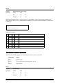
Using this online information guid e
The words on the left side of this screen are bookmark s for all the
topics in this guide .
Use the scroll ba r next to the bookmarks to find any topic you
want. Click a bookmark to instantly jump to its topic. (If you wish,
you can increase the size of the bookmark area by dragging the
dividing bar to the right. )
Use the zoom tools to magnify or reduce the page display.
Click the Find button if you want to search for a particular term.
(However, using the bookmarks is usually quicker. )
Complete online documentation for Acrobat Reader is located in the Help directory for Acrobat Reader.
Return to main menu
EPSON®
Guide to
TM-U375/U375P
SEIKO EPSON CORPORATION
400609200
The programming examples in this manual are provided for the sole purpose of illustrating the
functions of the products. Seiko Epson Corporation makes no warranty, either expressed or implied,
as to their reliability and appropriateness for other uses.
All rights reserved. No part of this publication may be reproduced, stored in a retrieval system, or
transmitted in any form or by any means, mechanical, photocopying, recording, or otherwise,
without the prior written permission of Seiko Epson Corporation. No patent liability is assumed with
respect to the use of the information contained herein. While every precaution has been taken in the
preparation of this book, Seiko Epson Corporation assumes no responsibility for errors or omissions.
Neither is any liability assumed for damages resulting from the use of the information contained
herein.
Neither Seiko Epson Corporation nor its affiliates shall be liable to the purchaser of this product or
third parties for damages, losses, costs, or expenses incurred by purchaser or third parties as a result
of: accident, misuse, or abuse of this product or unauthorized modifications, repairs, or alterations to
this product, or (excluding the U.S.) failure to strictly comply with Seiko Epson Corporation’s
operating and maintenance instructions.
Seiko Epson Corporation shall not be liable against any damages or problems arising from the use of
any options or any consumable products other than those designated as Original Epson Products or
Epson Approved Products by Seiko Epson Corporation.
EPSON is a registered trademark of Seiko Epson Corporation.
ESC/POS is a trademark of Seiko Epson Corporation.
NOTICE: The contents of this manual are subject to change without notice.
Copyright© 1996 by Seiko Epson Corporation, Nagano, Japan.
ESC/POS™ Information Manual
Guide to TM–U375/U375P
9603-01
SEIKO EPSON CORPORATION
SYSTEM DEVICE DIVISION
2070 Kotobuki Koaka, Matsumoto-shi, Nagano-ken 399, Japan
Introduction
ESC/POS
The market for store automation equipment is changing rapidly with the widespread
introduction of POS (point of sale) terminals. These terminals are now appearing even in small
retail stores and specialty shops. They occupy a secure position in the range of applications
available for personal computers.
As more personal computers come to be used as POS terminals, the demand for matching
standardized peripheral devices is expected to rise. At present, however, many of the competing
POS terminal printer displays on the market employ mutually incompatible command sets. This
imposes limits on the expandability and range of applications possible with PC-based systems.
There is a need for a new command set designed to provide the expandability and universal
applicability demanded by the market.
To meet this need, Seiko Epson Corporation proposes the adoption of a newly developed
command set to standardize POS terminal peripheral devices: ESC/POS (Epson Standard Code
for Point of Sale).
The aim when developing ESC/POS was to create a set of control codes that could be used to
operate any output device connected to a POS terminal. These new codes are intended to replace
the mutually incompatible command sets previously in use.
TM/DM series models already support ESC/POS, and they have been evaluated highly in the
marketplace.
Seiko Epson Corporation plans to produce new models in the TM/DM series offering ESC/POS
support and to continue to work for the standardization of the entire POS environment to
promote the dissemination of ESC/POS.
About This Manual
❏ Chapter 1 contains a table of supported commands, descriptions of all the commands
arranged by function with program examples and print samples, and character code tables.
❏ Chapter 2 contains an example showing procedures and a program for combining system
processes with the TM-U375, DM-D202II, and a drawer.
❏ Chapter 3 contains a table of the commands listed by function type and a table showing
which commands are supported by various EPSON printers.
Rev. A
i
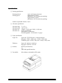
Features
The TM-U375 and TM-U375P are high-performance POS printers that can print on slip,
validation, and journal paper. The printers have the following features:
❏ World’s smallest multi-function 1.5 station printer.
❏ High-speed printing using logic seeking.
❏ Easy problem handling (e.g., paper jams or objects dropped into the printer) via a clamshell
mechanism.
❏ Two cut-sheet entrances: from above for validation paper and from the front for slip paper.
❏ Both journal and receipt printing with pressure-sensitive paper.
❏ Free-format printing in page mode.
❏ Various check printing patterns.
❏ Logic seeking and page mode for check printing.
❏ Movable platen for easy paper insertion.
❏ Paper load switch for easy paper roll loading.
❏ Control capability for two drawers.
❏ Selectable character size (7 × 9 or 5 × 9 font).
❏ Command protocol based on the ESC/POSTM standard.
❏ Automatic Status Back (ASB) function that automatically transmits changes in printer status.
❏ EPSON intelligent module connection (TM-U375 only).
❏ EPSON customer display series connection (TM-U375 only).
Options and Accessories
❏ EPSON power supply unit, PS-150 (not required when the TM-U375 (only) is connected to
an intelligent module).
❏ Direct connection display modules, DM-D102 and DM-D203 (for use with TM-U375 only).
❏ Pass-through customer display modules, DM-D101II and DM-D202II (for use with TM-U375
only).
❏ EPSON ribbon cassette, ERC-38.
ii
Rev. A
Specifications
❏ Printing specifications
Printing method:
Printing speed:
9-pin, serial impact dot matrix
Approximately 3.5 LPS
(40 columns, 16 CPI, continuous printing)
Approximately 5.4 LPS
(20 columns, 16 CPI, continuous printing)
Number of printable columns: 40/33
❏ Character specifications
Character fonts:
Character pitch:
Character size:
Character sets:
7 × 9/5 × 9
16/13.3 CPI
1.24(W) × 3.1(H) mm/1.56(W) × 3.1(H) mm
ASCII: 95 characters
International: 32 characters
Extended graphics: 128 characters × 6 pages
❏ Paper specifications
Paper size:
Paper roll: 75.5-76.5(W) mm × 83.0 mm diameter
Slip paper: 70(W) × 160(L) mm – 182(W) × 257(L) mm
Validation paper: 135(W) × 70(L) mm – 182(W) × 257(L) mm
Thickness:
Paper roll: 0.06 mm – 0.085 mm
Slip paper: 0.09 mm – 0.31 mm
❏ Interface:
RS-232 (serial interface)
or
IEEE-1284 (parallel interface)
❏ Data buffer:
4K or 40 bytes (selectable by DIP switch)
Rev. A
iii
Contents
Chapter 1 Command Descriptions
Using Bit Value Tables . . . . . . . . . . . . . . . . . . . . . . . . . . . . . . . . . . . . . . . . . . . . . . . . . . . . . . . . . . . . . . . . . . . . . . . . . . . . . . . . . 1-3
Print Commands . . . . . . . . . . . . . . . . . . . . . . . . . . . . . . . . . . . . . . . . . . . . . . . . . . . . . . . . . . . . . . . . . . . . . . . . . . . . . . . . . . . . . 1-4
Line Spacing Commands . . . . . . . . . . . . . . . . . . . . . . . . . . . . . . . . . . . . . . . . . . . . . . . . . . . . . . . . . . . . . . . . . . . . . . . . . . . . . . 1-7
Character Commands. . . . . . . . . . . . . . . . . . . . . . . . . . . . . . . . . . . . . . . . . . . . . . . . . . . . . . . . . . . . . . . . . . . . . . . . . . . . . . . . . . 1-8
Panel Button Command . . . . . . . . . . . . . . . . . . . . . . . . . . . . . . . . . . . . . . . . . . . . . . . . . . . . . . . . . . . . . . . . . . . . . . . . . . . . . . 1-18
Paper Sensor Commands . . . . . . . . . . . . . . . . . . . . . . . . . . . . . . . . . . . . . . . . . . . . . . . . . . . . . . . . . . . . . . . . . . . . . . . . . . . . . 1-19
Printing Paper Commands . . . . . . . . . . . . . . . . . . . . . . . . . . . . . . . . . . . . . . . . . . . . . . . . . . . . . . . . . . . . . . . . . . . . . . . . . . . . 1-21
Print Position Commands . . . . . . . . . . . . . . . . . . . . . . . . . . . . . . . . . . . . . . . . . . . . . . . . . . . . . . . . . . . . . . . . . . . . . . . . . . . . . 1-24
Bit-Image Commands . . . . . . . . . . . . . . . . . . . . . . . . . . . . . . . . . . . . . . . . . . . . . . . . . . . . . . . . . . . . . . . . . . . . . . . . . . . . . . . . 1-30
Status Commands . . . . . . . . . . . . . . . . . . . . . . . . . . . . . . . . . . . . . . . . . . . . . . . . . . . . . . . . . . . . . . . . . . . . . . . . . . . . . . . . . . . 1-32
Mechanism Control Commands . . . . . . . . . . . . . . . . . . . . . . . . . . . . . . . . . . . . . . . . . . . . . . . . . . . . . . . . . . . . . . . . . . . . . . . 1-40
Miscellaneous Function Commands . . . . . . . . . . . . . . . . . . . . . . . . . . . . . . . . . . . . . . . . . . . . . . . . . . . . . . . . . . . . . . . . . . . . 1-42
Character Code Tables . . . . . . . . . . . . . . . . . . . . . . . . . . . . . . . . . . . . . . . . . . . . . . . . . . . . . . . . . . . . . . . . . . . . . . . . . . . . . . . . 1-48
Chapter 2 Application
Chapter 3 Command Reference
Command Classification . . . . . . . . . . . . . . . . . . . . . . . . . . . . . . . . . . . . . . . . . . . . . . . . . . . . . . . . . . . . . . . . . . . . . . . . . . . . . . . 3-1
Reference Table . . . . . . . . . . . . . . . . . . . . . . . . . . . . . . . . . . . . . . . . . . . . . . . . . . . . . . . . . . . . . . . . . . . . . . . . . . . . . . . . . . . . . . . 3-6
iv
Rev. A
TM–U375/U375P Information Manual
Chapter 1
Command Descriptions
Following this table are all the commands organized by function and described with program
examples and print samples. The print samples are images of the printing results of the program
examples; they do not represent actual printing.
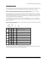
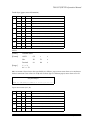
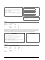
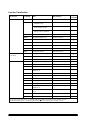
Supported Commands
Command
Name
Function Type
Page
Number
HT
Horizontal tab
Print position
1-27
LF
Print and line feed
Print
1-4
Print
1-5
1
FF
2
Print and eject cut sheet (in standard mode)
Print and return to standard mode (in page
mode)
CR
Print and carriage return
Print
1-4
CAN
Cancel print data in page mode
Character
1-17
DLE EOT
Real-time status transmission
Status
1-36
DLE ENQ
Real-time request to printer
Miscellaneous function
1-46
ESC SP
Set right-side character spacing
Character
1-9
ESC !
Select print mode(s)
Character
1-13
ESC $
Set absolute print position
Print position
1-24
ESC %
Select/cancel user-defined character set
Character
1-10
ESC &
Define user-defined characters
Character
1-10
ESC ✻
Select bit-image mode
Bit image
1-30
ESC –
Turn underline mode on/off
Character
1-14
ESC 2
Select default line spacing
Line spacing
1-7
ESC 3
Set line spacing
Line spacing
1-7
ESC <
Return home
Mechanism control
1-40
ESC =
Select peripheral device
Miscellaneous function
1-45
ESC ?
Cancel user-defined characters
Character
1-10
ESC @
Initialize printer
Miscellaneous function
1-43
ESC C
Set cut sheet eject length
Line spacing
1-8
ESC D
Set horizontal tab positions
Print position
1-27
ESC E
Turn emphasized mode on/off
Character
1-15
ESC G
Turn double-strike mode on/off
Character
1-15
ESC J
Print and feed paper
Print
1-6
ESC L
Select page mode
Miscellaneous function
1-46
ESC R
Select an international character set
Character
1-11
Rev. A
Command Descriptions 1-1
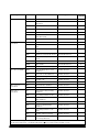
Command
Name
Function Type
Page
Number
ESC T
Select print direction in page mode
Print position
1-29
ESC U
Turn unidirectional printing mode on/off
Mechanism control
1-41
ESC V
Turn 90 ° clockwise rotation mode on/off
Character
1-17
ESC W
Set printing area in page mode
Print position
1-28
ESC \
Set relative print position
Print position
1-24
ESC a
Select justification
Print position
1-25
ESC c 0
Select paper type(s) for printing
Printing paper
1-21
ESC c 1
Select paper type(s) for command settings
Printing paper
1-22
ESC c 3
Select paper sensor(s) to output paper-end
signals
Paper sensor
1-20
ESC c 4
Select paper sensor(s) to stop printing
Paper sensor
1-19
ESC c 5
Enable/disable panel buttons
Panel button
1-18
ESC d
Print and feed n lines
Print
1-6
ESC f
Set cut sheet wait time
Printing paper
1-23
ESC p
Generate pulse
Miscellaneous function
1-45
ESC q
Paper release
Mechanism control
1-41
ESC t
Select character code table
Character
1-12
ESC u
Transmit peripheral device status
Status
1-39
ESC v
Transmit paper sensor status
Status
1-40
ESC {
Turn upside-down printing mode on/off
Character
1-16
GS ✻
Define downloaded bit image
Bit image
1-31
GS /
Print downloaded bit image
Bit image
1-31
GS E
Select head control method
Miscellaneous function
1-43
GS I
Transmit printer ID
Miscellaneous function
1-44
GS L
Set left margin
Print position
1-26
GS P
Set horizontal and vertical motion units
Miscellaneous function
1-42
GS W
Set printing area width
Print position
1-26
GS a
Enable/disable Automatic Status Back (ASB)
Status
1-33
GS r
Transmit status
Status
1-35
1-2 Command Descriptions
Rev. A
TM–U375/U375P Information Manual
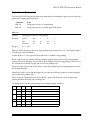
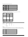
Using Bit Value Tables
For each command that has a complex method of determining the variable n, there is a table showing
how to calculate the variable in three numbering systems: binary, hexadecimal, and decimal.
When you look at the table, first find the value of each component of the variable. Then add the
values of the components together to determine the value of the variable n.
For example, here is how you would use the table below, which selects the print mode, to combine
double height, double width, and underline. In the table, you see that bit 4 on (or hex 10 or decimal
16) turns on double height, bit 5 on (or hex 20 or decimal 32) turns on double width, and bit 7 on (or
hex 80 or decimal 128) turns on underline mode.
To combine all three, turn on bits 4, 5, and 7, which is 10110000 in binary. Or you can add the hex
values 10, 20, and 80 for the hex sum of B0, or you can add the decimal values 16, 32, and 128 for the
decimal value of 176.
Therefore, you send the following to turn on double height, double width, and underline, depending
on the numbering system used:
ASCII
Hex
Decimal
Bit
ESC
1B
28
!
21
33
n
B0
176
Off/On
Hex
Decimal
Function
Off
00
0
Character font 5 x 9 selected.
On
01
1
Character font 7 x 9 selected.
—
—
—
Undefined.
Off
00
0
Emphasized mode not selected.
On
08
8
Emphasized mode selected.
Off
00
0
Double-height mode not selected.
On
10
16
Double-height mode selected.
Off
00
0
Double-width mode not selected.
On
20
32
Double-width mode selected.
—
—
—
Undefined.
Off
00
0
Underline mode not selected.
On
80
128
Underline mode selected.
0
1, 2
3
4
5
6
7
Note that the program examples throughout this chapter use decimal numbers, but binary, decimal,
and hexadecimal numbers all have the same printing results.
Rev. A
Command Descriptions 1-3
Print Commands
The TM-U375/U375P supports the following commands for printing characters and advancing
paper:
Command
Name
LF
Print and line feed
CR
Print and carriage return
FF
1
Print and eject cut sheet (in standard mode)
2
Print and return to standard mode (in page mode)
ESC J
Print and feed paper
ESC d
Print and feed n lines
LF
[Name]
Print and line feed
[Format]
ASCII
LF
Hex
0A
Decimal
10
LF prints the data in the print buffer and feeds one line. The amount of paper fed per line is based on
the value set using the line spacing command. The default setting is 1/6 inch.
Program Example
PRINT #1, "AAAAA"; CHR$(&HA);
PRINT #1, "BBBBB"; CHR$(&HA);
Print Sample
AAAAA
BBBBB
CR
[Name]
Print and carriage return
[Format]
ASCII
CR
Hex
0D
Decimal
13
CR prints one line of data from the print buffer and does not feed the paper. This command sets the
print starting position to the beginning of the line.
Program Example
PRINT #1, "AAAAA"; CHR$(&HD);
PRINT #1, "
BBBBB"; CHR$(&HA);
1-4 Command Descriptions
Print Sample
AAAAABBBBB
Rev. A
TM–U375/U375P Information Manual
FF
[Name]
[Format]
1
Print and eject cut sheet (in standard mode)
2
Print and return to standard mode (in page mode)
ASCII
FF
Hex
0C
Decimal
12
In standard mode, FF prints the data in the print buffer and ejects the cut sheet (slip or validation
paper). This command is enabled only when a cut sheet is selected for printing. When the eject
length has been set by ESC C, the printer ejects the cut sheet based on the current eject length
regardless of the cut-sheet paper sensor state. Otherwise, the printer ejects the cut sheet completely.
Paper from the paper roll is not ejected, even if it is also selected.
After cut-sheet ejection, the paper roll is selected for printing. The cut sheet is ejected in the forward
direction only.
In page mode, FF prints the data in the print buffer collectively and returns to standard mode. The
buffer data is deleted after being printed, but the paper is not ejected.
Program Example <standard mode>
PRINT #1, CHR$(&H1B);"c0";CHR$(4);← Select
PRINT #1, "AAAAA"; CHR$(&HA);
PRINT #1, "BBBBB"; CHR$(&HC);
slip
Print Sample <standard mode>
AAAAA
BBBBB
The paper is completely ejected.
Program Example <page mode>
PRINT #1, CHR$(&H1B);"L";←Select page mode
PRINT #1, CHR$(&H1B);"W";CHR$(0);CHR$(0);CHR$(0);
CHR$(0);CHR$(30);CHR$(0);CHR$(30);CHR$(0);
PRINT #1, CHR$(&H1B);"T";CHR$(0);
PRINT #1, "AAAAA"; CHR$(&HA);←Store characters for printing
PRINT #1, "BBBBB"; CHR$(&HA);←Store characters for printing
PRINT #1, "CCCCC"; CHR$(&HC);←Batch print
Rev. A
Print Sample <page mode>
AAAAA
BBBBB
CCCCC
Command Descriptions 1-5
ESC J n
[Name]
Print and feed paper
[Format]
ASCII
ESC
J
n
Hex
1B
4A
n
Decimal
27
74
n
[Range]
0 ≤ n ≤ 255
ESC J n prints the data in the print buffer and feeds the paper [n × (vertical or horizontal motion unit)]
inches. This command is used to temporarily feed a specific length without changing the line spacing
set by other commands. The maximum paper feed amount is 40 inches. When standard mode is
selected, the vertical motion unit set by GS P is used. When page mode is selected, the vertical or
horizontal motion unit set by GS P is used for the print direction set by ESC T.
Program Example
PRINT
PRINT
PRINT
PRINT
PRINT
#1,
#1,
#1,
#1,
#1,
Print Sample
CHR$(&H1D);"P";CHR$(160);CHR$(144);
"AAAAA"; CHR$(&HA);
"BBBBB"; CHR$(&H1B);"J";CHR$(72);
"CCCCC"; CHR$(&HA);
"DDDDD"; CHR$(&HA);
AAAAA
BBBBB
ESC J used to print one line and advance
the paper by 72/144 inch
CCCCC
DDDDD
ESC d n
[Name]
Print and feed n lines
[Format]
ASCII
ESC
d
n
Hex
1B
64
n
Decimal
27
100
n
[Range]
0 ≤ n ≤ 255
ESC d n prints the data in the print buffer and feeds n lines. The amount of paper fed per line is based
on the value set using the line spacing command. The maximum paper feed amount is 40 inches. The
default setting of the paper feed amount is 1/6 inch.
Program Example
PRINT #1, "AAAAA"; CHR$(&HA);
PRINT #1, "BBBBB"; CHR$(&H1B);"d";CHR$(6);
PRINT #1, "CCCCC"; CHR$(&HA);
Print Sample
AAAAA
BBBBB
ESC d used to print one line and
advance the paper by six lines
CCCCC
1-6 Command Descriptions
Rev. A
TM–U375/U375P Information Manual
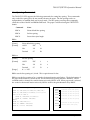
Line Spacing Commands
The TM-U375/U375P supports the following commands for setting line spacing. These commands
only set the line spacing; they do not actually advance the paper. The line spacing can be set
independently in standard mode and in page mode. The line spacing set using these commands
effects the results of the LF and ESC d commands. The paper is advanced using the PAPER FEED
button.
Command
Name
ESC 2
Select default line spacing
ESC 3
Set line spacing
ESC C
Set cut sheet eject length
ESC 2
[Name]
Select default line spacing
[Format]
ASCII
ESC
2
Hex
1B
32
Decimal
27
50
ESC 3 n
[Name]
Set line spacing
[Format]
ASCII
ESC
3
n
Hex
1B
33
n
Decimal
27
51
n
[Range]
0 ≤ n ≤ 255
ESC 2 sets the line spacing to 1/6 inch. This is equivalent to 12 dots.
ESC 3 n sets the line spacing to [n × (vertical or horizontal motion unit)] inches. The default setting of
the paper feed amount is 1/6 inch (n=24). The maximum line spacing amount is 40 inches. When
standard mode is selected, the vertical motion unit set by GS P is used. When page mode is selected,
the vertical or horizontal motion unit set by GS P is used for the print direction set by ESC T.
Program Example
PRINT #1, CHR$(&H1D);"P";CHR$(160);CHR$(144);
PRINT #1, CHR$(&H1B);"c1";CHR$(1);← Select paper roll
FOR n=10 TO 60 STEP 10
PRINT #1, CHR$(&H1B);"3";CHR$(n);
PRINT #1, "AAAAA"; CHR$(&HA);
NEXT n
PRINT #1, CHR$(&H1B);"2";
PRINT #1, "BBBBB"; CHR$(&HA);
PRINT #1, "CCCCC"; CHR$(&HA);
Rev. A
Print Sample
AAAAA
AAAAA
AAAAA
AAAAA
10/144-inch (5-dot) line spacing
20/144-inch (10-dot) line spacing
30/144-inch (15-dot) line spacing
40/144-inch (20-dot) line spacing
AAAAA
50/144-inch (25-dot) line spacing
AAAAA
60/144-inch (30-dot) line spacing
BBBBB
CCCCC
1/6-inch (12-dot) line spacing
Command Descriptions 1-7
ESC C n
[Name]
Set cut sheet eject length
[Format]
ASCII
ESC
C
n
Hex
1B
43
n
Decimal
27
67
n
0 ≤ n ≤ 255
[Range]
ESC C n sets the eject length for cut sheet (slip or validation paper) to n lines. The maximum eject
length is 40 inches. The default setting for the eject length is n=0. This length is calculated by [n × line
spacing setting]. No eject length is set if n=0. When n=0, the paper is ejected continuously until it is
completely out of the printer. The eject length set by this command is used by the FF command. This
command sets the eject length for the paper specified by ESC c 1.
Program Example
PRINT
PRINT
PRINT
PRINT
PRINT
#1,
#1,
#1,
#1,
#1,
CHR$(&H1B);"c1";CHR$(4);←Select slip
CHR$(&H1B);"C";CHR$(8);←Set eject length
CHR$(&H1B);"c0";CHR$(4);←Select slip
"AAAAA"; CHR$(&HA);
"BBBBB"; CHR$(&HC);
Print Sample
AAAAA
BBBBB
Eject length set to 8 lines using
ESC C
Character Commands
The TM-U375/U375P supports the following commands for setting character font and size:
Command
Name
ESC SP
Set right-side character spacing
ESC %
Select/cancel user-defined character set
ESC &
Define user-defined characters
ESC ?
Cancel user-defined characters
ESC R
Select an international character set
ESC t
Select character code table
ESC !
Select print mode(s)
ESC –
Turn underline mode on/off
ESC E
Turn emphasized mode on/off
ESC G
Turn double-strike mode on/off
ESC {
Turn upside-down printing mode on/off
ESC V
Turn 90° clockwise rotation mode on/off
CAN
Cancel print data in page mode
1-8 Command Descriptions
Rev. A
TM–U375/U375P Information Manual
ESC SP n
[Name]
Set right-side character spacing
[Format]
ASCII
ESC
SP
n
Hex
1B
20
n
Decimal
27
32
n
[Range]
0 ≤ n ≤ 255
ESC SP n sets the right-side character spacing to [n × (horizontal or vertical motion unit)] inches. It is
used to change the spacing between characters. The default setting is n=0. When standard mode is
selected, the horizontal motion unit set by GS P is used. When page mode is selected, the vertical or
horizontal motion unit set by GS P is used for the print direction set by ESC T.
The right-side character spacing can be set independently in standard mode and in page mode.
Program Example
PRINT
PRINT
PRINT
PRINT
PRINT
PRINT
PRINT
Rev. A
#1,
#1,
#1,
#1,
#1,
#1,
#1,
CHR$(&H1D);"P";CHR$(160);CHR$(144);
CHR$(&H1B);" ";CHR$(0);← Character spacing set to 0
"AAAAA"; CHR$(&HA);
CHR$(&H1B);" ";CHR$(6);← Character spacing set to 6
"BBBBB"; CHR$(&HA);
CHR$(&H1B);" ";CHR$(12);← Character spacing set to 12
"CCCCC"; CHR$(&HA);
Print Sample
AAAAA ← 0-inch right-side character spacing
BBBBB ← 6/160-inch right-side character spacing
C C C C C ← 12/160-inch right-side character spacing
Command Descriptions 1-9
ESC % n
[Name]
Select/cancel user-defined character set
[Format]
ASCII
ESC
%
n
Hex
1B
25
n
Decimal
27
37
n
[Range]
0 ≤ n ≤ 255
ESC & y c1 c2 [x1 d1 ... d(y × x1)] ... [xk d1 ... d(y × xk)]
[Name]
Define user-defined characters
[Format]
ASCII
ESC
&
y
c1 c2 [x1 d1 ... d(y × x1)] ... [xk d1 ... d(y × xk)]
Hex
1B
26
y
c1 c2 [x1 d1 ... d(y × x1)] ... [xk d1 ... d(y × xk)]
Decimal
27
38
y
c1 c2 [x1 d1 ... d(y × x1)] ... [xk d1 ... d(y × xk)]
[Range]
y=2
32 ≤ c1 ≤ c2 ≤ 126
0 ≤ x ≤ 6 (5 × 9 font)
0 ≤ x ≤ 10 (7 × 9 font)
0 ≤ d1 ... d(y × xk) ≤ 255
k = c2-c1+1
ESC ? n
[Name]
Cancel user-defined characters
[Format]
ASCII
ESC
?
n
Hex
1B
3F
n
Decimal
27
63
n
[Range]
32 ≤ n ≤ 126
ESC % n selects or cancels the user-defined character set. When the LSB (least significant bit) of n is 1,
the user-defined character set is selected. When it is 0, the internal character set is selected; this is the
default setting.
ESC & y c1 c2 [x1 d1 ... d(y × x1)] ... [xk d1 ... d(y × xk)] defines user-defined characters from character
code c1 to c2. y and x are the configuration of a user-defined character. y specifies the number of
bytes in the vertical direction. x specifies the number of dots in the horizontal direction. Character
codes from the alphanumeric characters (20H (decimal 32) to 7EH (decimal 126)) can be defined by c1
and c2. Data (d) specifies a bit printed to 1 and not printed to 0. As the default, user-defined
characters are not defined and the internal character set is printed. Once the user-defined characters
have been defined, they are available until ESC @, ESC ?, or GS ✻ is executed; the user-defined
characters are redefined; the power is turned off; or the printer is reset. When this command is
executed, the downloaded bit image is canceled.
1-10 Command Descriptions
Rev. A
TM–U375/U375P Information Manual
ESC ? n cancels the user-defined characters defined for the character code n. After the user-defined
characters are canceled, the internal character set is printed.
Program Example
Program Example (continued)
y=2
PRINT #1, CHR$(&H1B);"&";CHR$(y);"AC";
x=7: PRINT #1, CHR$(x);
FOR i=1 TO y*x
READ d: PRINT #1, CHR$(d);
NEXT i
x=9: PRINT #1, CHR$(x);
FOR i=1 TO y*x
READ d: PRINT #1, CHR$(d);
NEXT i
x=9: PRINT #1, CHR$(x);
FOR i=1 TO y*x
READ d: PRINT #1, CHR$(d);
NEXT i
PRINT
PRINT
PRINT
PRINT
PRINT
PRINT
#1,
#1,
#1,
#1,
#1,
#1,
DATA &H30,&H00,&H78,&H00,&HFC,&H00,&H78,&H00
DATA &H30,&H00,&H00,&H00,&H00,&H00
DATA &H18,&H00,&H24,&H00,&H42,&H00,&H81,&H00
DATA &H42,&H00,&H24,&H00,$H18,&H00,&H00,&H00
DATA &H00,&H00
Defines the
user-defined
characters as
"A", "B", and "C"
DATA &H18,&H00,&H28,&H00,&H4F,&H80,&H80,&H80
DATA &H4F,&H80,&H28,&H00,&H18,&H00,&H00,&H00
DATA &H00,&H00
Print Sample
CHR$(&H1B);"%";CHR$(0); ← Select the internal character
"A B C D E"; CHR$(&HA); set
CHR$(&H1B);"%";CHR$(1); ← Select the user-defined
"A B C D E"; CHR$(&HA): character set
CHR$(&H1B);"?";"A"; ← Cancel the user-defined character
"A B C D E"; CHR$(&HA);
A B C D E ← Characters from internal character set
+ ◊ ↑ D E ← Characters from user-defined character set
A ◊ ↑ D E ← Characters from user-defined character set
(cancel one character)
ESC R n
[Name]
Select an international character set
[Format]
ASCII
ESC
R
n
Hex
1B
52
n
Decimal
27
82
n
[Range]
Rev. A
0 ≤ n ≤ 10
Command Descriptions 1-11
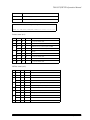
ESC R n selects an international character set n as follows. The default value is U.S.A. (n=0).
n
Country
0
U.S.A.
1
France
2
Germany
3
U.K.
4
Denmark I
5
Sweden
6
Italy
7
Spain
8
Japan
9
Norway
10
Denmark lI
Program Example
Print Sample
FOR n=0 TO 10
PRINT #1, CHR$(&H1B);"R";CHR$(n);
PRINT #1, "# $ @ [ \ ] ^ ` { ¦ } ~"; CHR$(&HA);
NEXT n
#
#
#
£
#
#
#
Pt
#
#
#
$
$
$
$
$
¤
$
$
$
¤
$
@
à
§
@
@
É
@
@
@
É
É
[
°
Ä
[
Æ
Ä
°
¡
[
Æ
Æ
\
ç
Ö
\
Ø
Ö
\
Ñ
¥
Ø
Ø
]
§
Ü
]
Å
Å
é
¿
]
Å
Å
^
^
^
^
^
Ü
^
^
^
Ü
Ü
`
`
`
`
`
é
ù
`
`
é
é
{
é
ä
{
æ
ä
à
¨
{
æ
æ
¦
ù
ö
¦
ø
ö
ò
ñ
¦
ø
ø
}
è
ü
}
å
å
è
}
}
å
å
←
¨ ←
ß ←
~
←
~
←
ü ←
ì ←
~
←
~
←
ü ←
ü ←
~
n=0 (Default setting)
n=1
n=2
n=3
n=4
n=5
n=6
n=7
n=8
n=9
n=10
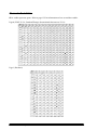
ESC t n
[Name]
Select character code table
[Format]
ASCII
ESC
t
n
Hex
1B
74
n
Decimal
27
116
n
[Range]
0≤n≤5
254 ≤ n ≤ 255
1-12 Command Descriptions
Rev. A
TM–U375/U375P Information Manual
ESC t n selects a page n from the character code table as follows. The alphanumeric characters (20H
(decimal 32) to 7FH (decimal 127)) are the same for each page. The graphic characters (80H (decimal
128) to FFH (decimal 255)) are different for each page. The default setting is page 0.
n
Character Code Table
0
Page 0 [PC437 (U.S.A. , Standard Europe)]
1
Page 1 [Katakana]
2
Page 2 [PC850 (Multilingual)]
3
Page 3 [PC860 (Portuguese)]
4
Page 4 [PC863 (Canadian-French)]
5
Page 5 [PC865 (Nordic)]
254
Page 254 [space page]
255
Page 255 [space page]
Program Example
PRINT
PRINT
GOSUB
PRINT
GOSUB
END
Print Sample
#1, CHR$(&H1B);"!";CHR$(0);
#1, CHR$(&H1B);"t";CHR$(0); ← Select page 0
printing
#1, CHR$(&H1B);"t";CHR$(1); ← Select page 1
printing
Page 0
printing:
FOR i=&H20 TO &H7F
PRINT #1, CHR$(i);
NEXT i
PRINT #1, CHR$(&HA);
FOR i=&H80 TO &HFF
PRINT #1, CHR$(i);
NEXT i
PRINT #1, CHR$(&HA);
RETURN
Page 1
ESC ! n
[Name]
Select print mode(s)
[Format]
ASCII
ESC
!
n
Hex
1B
21
n
Decimal
27
33
n
[Range]
Rev. A
0 ≤ n ≤ 255
Command Descriptions 1-13
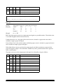
ESC ! n selects print modes using n as follows. The default setting is n=1. This command cannot be
used with the 7 × 9 font or for emphasized printing in page mode. If the 7 × 9 font or emphasized
printing is selected or canceled in page mode, an internal flag is activated and this command is
enabled when the printer returns to standard mode.
Bit
Off/On
Hex
Decimal
Function
Off
00
0
Character font 5 x 9 selected.
On
01
1
Character font 7 x 9 selected.
—
—
—
Undefined.
Off
00
0
Emphasized mode not selected.
On
08
8
Emphasized mode selected.
Off
00
0
Double-height mode not selected.
On
10
16
Double-height mode selected.
Off
00
0
Double-width mode not selected.
On
20
32
Double-width mode selected.
–
–
–
Undefined.
Off
00
0
Underline mode not selected.
On
80
128
Underline mode selected.
0
1, 2
3
4
5
6
7
Program Example
PRINT
PRINT
PRINT
PRINT
PRINT
PRINT
PRINT
PRINT
PRINT
PRINT
PRINT
PRINT
PRINT
PRINT
PRINT
PRINT
#1,
#1,
#1,
#1,
#1,
#1,
#1,
#1,
#1,
#1,
#1,
#1,
#1,
#1,
#1,
#1,
Print Sample
CHR$(&H1B);"!";CHR$(0); "AA";
CHR$(&H1B);"!";CHR$(8); "BB";
CHR$(&H1B);"!";CHR$(16); "CC";
CHR$(&H1B);"!";CHR$(24); "DD";
CHR$(&H1B);"!";CHR$(32); "EE";
CHR$(&H1B);"!";CHR$(40); "FF";
CHR$(&H1B);"!";CHR$(48); "GG";
CHR$(&H1B);"!";CHR$(56); "HH"; CHR$(&HA);
CHR$(&H1B);"!";CHR$(129); "AA";
CHR$(&H1B);"!";CHR$(137); "BB";
CHR$(&H1B);"!";CHR$(145); "CC";
CHR$(&H1B);"!";CHR$(153); "DD";
CHR$(&H1B);"!";CHR$(161); "EE";
CHR$(&H1B);"!";CHR$(169); "FF";
CHR$(&H1B);"!";CHR$(177); "GG";
CHR$(&H1B);"!";CHR$(185); "HH"; CHR$(&HA);
←
5 x 9 font
←7
x 9 font
with underline
AA: Normal
BB: Emphasized
CC: Double-height
DD: Emphasized + Double-height
EE: Double-width
FF: Emphasized + Double-width
GG: Double-height + Double-width
HH: Emphasized + Double-height + Double-width
ESC – n
[Name]
Turn underline mode on/off
[Format]
ASCII
ESC
–
n
Hex
1B
2D
n
Decimal
27
45
n
[Range]
n = 0, 1, 48, 49
1-14 Command Descriptions
Rev. A
TM–U375/U375P Information Manual
ESC – n turns underline mode on or off. When n=1 or 49, underline mode is turned on, and when n=0
or 48, underline mode is turned off. When underline mode is on, 90° clockwise rotated characters
cannot be underlined. The default setting is n=0.
Program Example
PRINT
PRINT
PRINT
PRINT
#1,
#1,
#1,
#1,
Print Sample
CHR$(&H1B);"-";CHR$(1); ← Select
"AAAAA";CHR$(&HA);
CHR$(&H1B);"-";CHR$(0); ← Cancel
"BBBBB";CHR$(&HA);
AAAAA ← Underline mode turned on
BBBBB ← Underline mode turned off
ESC E n
[Name]
Turn emphasized mode on/off
[Format]
ASCII
ESC
E
n
Hex
1B
45
n
Decimal
27
69
n
[Range]
0 ≤ n ≤ 255
ESC E n turns emphasized mode on or off. When the LSB (least significant bit) of n is 1, emphasized
mode is turned on; when it is 0, emphasized mode is turned off. The default setting is n=0.
Emphasized and double-strike printing appear the same. This command is enabled only in standard
mode. If this command is entered in page mode, an internal flag is activated and the command is
enabled when the printer returns to standard mode.
Program Example
PRINT
PRINT
PRINT
PRINT
#1,
#1,
#1,
#1,
Print Sample
CHR$(&H1B);"E";CHR$(1); ← Select
"AAAAA"; CHR$(&HA);
CHR$(&H1B);"E"; CHR$(0); ← Cancel
"BBBBB"; CHR$(&HA);
AAAAA ← Emphasized
BBBBB ← Emphasized
mode turned on
mode turned off
ESC G n
[Name]
Turn double-strike mode on/off
[Format]
ASCII
ESC
G
n
Hex
1B
47
n
Decimal
27
71
n
[Range]
Rev. A
0 ≤ n ≤ 255
Command Descriptions 1-15
ESC G n turns double-strike mode on or off. When the LSB (least significant bit) of n is 1, doublestrike mode is turned on; when it is 0, double-strike mode is turned off. The default setting is n=0.
Double-strike and emphasized printing appear the same. This command is enabled only in standard
mode. If this command is entered in page mode, an internal flag is activated and the command is
enabled when the printer returns to standard mode.
Program Example
PRINT
PRINT
PRINT
PRINT
#1,
#1,
#1,
#1,
Print Sample
CHR$(&H1B);"G";CHR$(1); ← Select
"AAAAA"; CHR$(&HA);
CHR$(&H1B);"G";CHR$(0); ← Cancel
"BBBBB"; CHR$(&HA);
AAAAA ← Double-strike
BBBBB ← Double-strike
mode turned on
mode turned off
ESC { n
[Name]
Turn upside-down printing mode on/off
[Format]
ASCII
ESC
{
n
Hex
1B
7B
n
Decimal
27
123
n
[Range]
0 ≤ n ≤ 255
ESC { n turns upside-down printing mode on or off. When the LSB (least significant bit) of n is 1,
upside-down printing mode is turned on; when it is 0, upside-down printing mode is turned off. The
default setting is n=0. When upside-down mode is turned on, the printer prints 180°-rotated
characters from right to left. The line printing order is not reversed; therefore be careful of the order
of the data transmitted. In standard mode, this command is enabled only when input at the
beginning of a line. In page mode, the print direction is set with ESC T, an internal flag is activated,
and this command is enabled when the printer returns to standard mode.
Program Example
#1, CHR$(&H1B);"{";CHR$(0); ← Cancel
printing
#1, CHR$(&H1B);"{";CHR$(1); ← Select
printing
printing:
PRINT #1, "ABCDE"; CHR$(&HA);
PRINT #1, "BCDEF"; CHR$(&HA);
RETURN
1-16 Command Descriptions
Normal printing
ABCDE
BCDEF
BCDEF
ABCDE
PRINT
GOSUB
PRINT
GOSUB
END
Print Sample
Upside-down
printing
Rev. A
TM–U375/U375P Information Manual
ESC V n
[Name]
Turn 90° clockwise rotation mode on/off
[Format]
ASCII
ESC
V
n
Hex
1B
56
n
Decimal
27
86
n
[Range]
0≤n≤2
48 ≤ n ≤ 50
ESC V n turns 90° clockwise rotation mode on or off. When n=1 or 49, 90° clockwise rotation mode
(1-dot character spacing) is turned on; when n=2 or 50, 90° clockwise rotation mode (1.5-dot character
spacing) is turned on; and when n=0 or 48, this mode is turned off. The default setting is n=0. The
characters do not rotate when both the 7 × 9 font and the 90° clockwise rotation mode are selected,
because selecting the 7 × 9 font is higher priority. This command is enabled only in standard mode. If
this command is entered in page mode, an internal flag is activated and the command is enabled
when the printer returns to standard mode.
Program Example
AAA A A A
BBB B B B
CCC C C C
ABC
printing:
PRINT #1,
PRINT #1,
PRINT #1,
PRINT #1,
PRINT #1,
PRINT #1,
PRINT #1,
PRINT #1,
PRINT #1,
RETURN
Right-side spacing
ABC
#1, CHR$(&H1D);"P";CHR$(160);CHR$(144);
#1, CHR$(&H1B);"3";CHR$(10);
#1, CHR$(&H1B);"V";CHR$(1);← Select
printing
#1, CHR$(&H1B);"2";
#1, CHR$(&H1B);"V";CHR$(0);← Cancel
printing
ABC
ABC
ABC
ABC
PRINT
PRINT
PRINT
GOSUB
PRINT
PRINT
GOSUB
END
Print Sample
Line
spacing
Line
spacing
ESC V 1
ESC V 0
Right-side spacing
CHR$(&H1B);" ";CHR$(0); "AAA";
CHR$(&H1B);" ";CHR$(10); "AAA";
CHR$(&HA);
CHR$(&H1B);" ";CHR$(0); "BBB"
CHR$(&H1B);" ";CHR$(10); "BBB";
CHR$(&HA);
CHR$(&H1B);" ";CHR$(0); "CCC";
CHR$(&H1B);" ";CHR$(10); "CCC";
CHR$(&HA);iCHR$(&HA);
CAN
[Name]
Cancel print data in page mode
[Format]
ASCII
CAN
Hex
18
Decimal
24
Rev. A
Command Descriptions 1-17
CAN deletes all the print data for the current print job in page mode. This command is enabled only
in page mode.
Program Example
Print Sample
PRINT #1, CHR$(&H1B);"L";← Select page mode
PRINT #1, CHR$(&H1B);"W";CHR$(0);CHR$(0);CHR$(0);
CHR$(0);CHR$(120);CHR$(0);CHR$(100);CHR$(0);
PRINT #1, CHR$(&H1B);"T";CHR$(0);
FOR i=1 TO 200
PRINT #1, "A";
NEXT i
PRINT #1, CHR$(&H1B);"W";CHR$(30);CHR$(0);CHR$(30);
CHR$(0);CHR$(30);CHR$(0);CHR$(30);CHR$(0);
PRINT #1, CHR$(&H18);← Cancel print data
AAAAAAAAAAAAAAAAAAAA
AAAAAAAAAAAAAAAAAAAA
AAAAAAAAAAAAAAAAAAAA
AAAAA
AAAAAAAAAA
AAAAA
AAAAAAAAAA
AAAAA
AAAAAAAAAA
AAAAAAAAAAAAAAAAAAAA
AAAAAAAAAAAAAAAAAAAA
AAAAAAAAAAAAAAAAAAAA
AAAAAAAAAAAAAAAAAAAA
PRINT #1, CHR$(&HC);← Batch
print
Panel Button Command
The TM-U375/U375P supports the following command for enabling and disabling the panel buttons
(PAPER FEED and RELEASE):
Command
Name
ESC c 5
Enable/disable panel buttons
ESC c 5 n
[Name]
Enable/disable panel buttons
[Format]
ASCII
ESC
c
5
n
Hex
1B
63
35
n
Decimal
27
99
53
n
[Range]
0 ≤ n ≤ 255
ESC c 5 n enables or disables the PAPER FEED and RELEASE buttons. When the LSB (least significant
bit) of n is 1, these buttons are disabled; when it is 0, these buttons are enabled. The default setting is
n=0. To prevent problems caused by accidentally pressing the buttons, use this command to disable
them. When the printer cover is open, the PAPER FEED button is disabled and the RELEASE button is
enabled, regardless of the setting of this command.
Program Example
PRINT #1, CHR$(&H1B);"c5";CHR$(1); ←
1-18 Command Descriptions
Disable panel buttons
Rev. A
TM–U375/U375P Information Manual
Paper Sensor Commands
The TM-U375/U375P supports the following commands for controlling the paper sensor(s) that stop
printing and output paper-end signals:
Command
Name
ESC c 4
Select paper sensor(s) to stop printing
ESC c 3
Select paper sensor(s) to output paper-end signals
ESC c 4 n
[Name]
Select paper sensor(s) to stop printing
[Format]
ASCII
ESC
c
4
n
Hex
1B
63
34
n
Decimal
27
99
52
n
0 ≤ n ≤ 255
[Range]
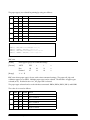
ESC c 4 n selects the paper sensor that stops printing when the paper runs out. The default setting is
n=0 (all paper sensors disabled).
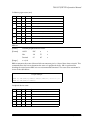
If either bit 0 or 1 is 1, the paper roll near-end sensor is enabled to stop printing.
When a paper sensor is enabled with this command, printing stops only when the corresponding
paper is selected for printing. It is possible to select multiple sensors to stop printing. Then if any of
the selected sensors detects a paper-end or near-end, printing stops.
When the paper roll near-end sensor detects a near-end, printing stops after printing the current line
and feeding the paper.
When DIP switch 2-3 is off and the paper roll near-end sensor detects a paper near-end, the printer
goes off-line after printing stops.
When the slip or validation ejection sensor detects a paper-end, the printer ejects the paper after
printing and then enters the paper waiting state.
The paper sensor(s) used to stop printing are selected by using n as follows:
Bit
Off/On
Hex
Decimal
Function
Off
00
0
Paper roll near-end sensor disabled.
On
01
1
Paper roll near-end sensor enabled.
Off
00
0
Paper roll near-end sensor disabled.
On
02
2
Paper roll near-end sensor enabled.
-
-
-
Undefined.
Off
00
0
Slip ejection sensor disabled.
On
20
32
Slip ejection sensor enabled.
0
1
2-4
5
Rev. A
Command Descriptions 1-19
Bit
Off/On
Hex
Decimal
Function
6
-
-
-
Undefined.
Off
00
0
Validation ejection sensor disabled.
On
80
128
Validation ejection sensor enabled.
7
Program Example
PRINT #1, CHR$(&H1B);"c4";CHR$(1); ← Paper
roll near-end sensor enabled
ESC c 3 n
[Name]
Select paper sensor(s) to output paper-end signals
[Format]
ASCII
ESC
c
3
n
Hex
1B
63
33
n
Decimal
27
99
51
n
0 ≤ n ≤ 255
[Range]
ESC c 3 n selects paper sensor(s) to output paper-end signals to a parallel interface. The default value
is to enable the paper roll near-end sensor (n=3).
If either bit 0 or bit 1 is 1, the paper roll near-end sensor is selected as a paper-end sensor that is
enabled to output a paper-end signal.
If any of bits 4-7 are 1, the cut-sheet (slip or validation paper) sensor is selected as a paper-end sensor
that is enabled to output a paper-end signal.
When both of these sensors are selected to output signals and either one detects a paper-end, the
paper-end signal is output. This command is enabled only with a parallel interface and is ignored
with a serial interface.
The paper sensor(s) used to output paper-end signals are selected by using n as follows:
Bit
Off/On
Hex
Decimal
Function
Off
00
0
Paper roll near-end sensor disabled.
On
01
1
Paper roll near-end sensor enabled.
Off
00
0
Paper roll near-end sensor disabled.
On
02
2
Paper roll near-end sensor enabled.
-
-
-
Undefined.
Off
00
0
Cut-sheet (slip or validation) sensor disabled.
On
10
16
Cut-sheet (slip or validation) sensor enabled.
Off
00
0
Cut-sheet (slip or validation) sensor disabled.
On
20
32
Cut-sheet (slip or validation) sensor enabled.
0
1
2-3
4
5
1-20 Command Descriptions
Rev. A
TM–U375/U375P Information Manual
Bit
Off/On
Hex
Decimal
Function
Off
00
0
Cut-sheet (slip or validation) sensor disabled.
On
40
64
Cut-sheet (slip or validation) sensor enabled.
Off
00
0
Cut-sheet (slip or validation) sensor disabled.
On
80
128
Cut-sheet (slip or validation) sensor enabled.
6
7
Program Example
PRINT #1, CHR$(&H1B);"c3";CHR$(17); ←
Both sensors enabled
Printing Paper Commands
The TM-U375/U375P supports the following commands for controlling printing paper:
Command
Name
ESC c 0
Select paper type(s) for printing
ESC c 1
Select paper type(s) for command settings
ESC f
Set cut sheet wait time
ESC c 0 n
[Name]
Select paper type(s) for printing
[Format]
ASCII
ESC
c
0
n
Hex
1B
63
30
n
Decimal
27
99
48
n
[Range]
1 ≤ n ≤ 11
ESC c 0 n selects paper type(s) for printing. The paper roll, slip, and validation paper are available.
The paper roll and slip or validation paper can be selected simultaneously. Slip and validation paper
cannot be selected simultaneously. When previously disabled slip or validation paper is enabled, the
printer waits for the slip or validation paper to be inserted. When previously enabled slip or
validation paper is disabled, the printer ejects the paper. The paper roll is enabled by the default
value (n=1). If either bit 0 or 1 is 1, the paper roll is selected.
When the paper roll and slip or validation paper are selected simultaneously, the paper roll must
contain pressure-sensitive paper or the image will not be printed.
This command is enabled only when input at the beginning of a line in standard mode. This
command is not valid in page mode.
Rev. A
Command Descriptions 1-21
The paper type(s) are selected for printing by using n as follows:
Bit
Off/On
Hex
Decimal
Function
Off
00
0
Paper roll disabled.
On
01
1
Paper roll enabled.
Off
00
0
Paper roll disabled.
On
02
2
Paper roll enabled.
Off
00
0
Slip paper disabled.
On
04
4
Slip paper enabled.
Off
00
0
Validation paper disabled.
On
08
8
Validation paper enabled.
—
—
—
Undefined.
0
1
2
3
4-7
Program Example
PRINT
PRINT
PRINT
PRINT
#1,
#1,
#1,
#1,
CHR$(&H1B);"c0";CHR$(4); ← Select slip
"AAAAA"; CHR$(&HA); ← Print on slip
CHR$(&H1B);"c0";CHR$(1); ← Select paper roll
"BBBBB"; CHR$(&HA); ← Print on paper roll
ESC c 1 n
[Name]
Select paper type(s) for command settings
[Format]
ASCII
ESC
c
1
n
Hex
1B
63
31
n
Decimal
27
99
49
n
[Range]
1 ≤ n ≤ 15
ESC c 1 n selects paper type(s) for use with various command settings. The paper roll, slip, and
validation paper are available. Multiple paper types can be selected. The default is all paper types
selected (n=15). If either bit 0 or 1 is 1, the paper roll is selected.
The paper types selected can be used with these commands: ESC 2, ESC 3, ESC C, GS L, and GS W.
The value of n is used as follows:
Bit
Off/On
Hex
Decimal
Function
Off
00
0
Paper roll disabled.
On
01
1
Paper roll enabled.
Off
00
0
Paper roll disabled.
On
02
2
Paper roll enabled.
Off
00
0
Slip paper disabled.
On
04
4
Slip paper enabled.
0
1
2
1-22 Command Descriptions
Rev. A
TM–U375/U375P Information Manual
Bit
Off/On
Hex
Decimal
Function
Off
00
0
Validation paper disabled.
On
08
8
Validation paper enabled.
—
—
—
Undefined.
3
4-7
Program Example
PRINT
PRINT
PRINT
PRINT
#1,
#1,
#1,
#1,
CHR$(&H1B);"c1";CHR$(1); ← Select paper roll
CHR$(&H1B);"3";CHR$(12); ← Set line spacing for
CHR$(&H1B);"c1";CHR$(4); ← Select slip paper
CHR$(&H1B);"3";CHR$(24); ← Set line spacing for
paper roll
slip paper
ESC f t1 t2
[Name]
Set cut sheet wait time
[Format]
ASCII
ESC
f
t1
t2
Hex
1B
66
t1
t2
Decimal
27
102
t1
t2
[Range]
0 ≤ t1 ≤ 15
0 ≤ t2 ≤ 64
ESC f t1 t2 sets the time that the printer waits for cut sheet (slip or validation paper) to be inserted to
t1 × 1 minutes, and the time from insertion of the sheet to the start of printing to t2 × 0.1 seconds.
When t1=0, the sheet waiting time is not set and the printer continues waiting for a sheet to be
inserted. The default for the sheet waiting time is not set, and the start operation time is set to 1
second (t1=0, t2=10). This setting alone, however, does not cause the printer to immediately start
waiting for a sheet to be inserted. The setting becomes effective when ESC c 0 is used. DLE ENQ is
used to cancel the sheet waiting state.
Program Example
PRINT #1, CHR$(&H1B);"f";CHR$(15);CHR$(20);
PRINT #1, CHR$(&H1B);"c0";CHR$(4); ← Select slip
PRINT #1, "AAAAA"; CHR$(&HA);
Rev. A
Command Descriptions 1-23
Print Position Commands
The TM-U375/U375P supports the following commands for setting the print position:
Command
Name
ESC $
Set absolute print position
ESC \
Set relative print position
ESC a
Select justification
GS L
Set left margin
GS W
Set printing area width
HT
Horizontal tab
ESC D
Set horizontal tab positions
ESC W
Set printing area in page mode
ESC T
Select print direction in page mode
ESC $ n L n H
[Name]
Set absolute print position
[Format]
ASCII
ESC
$
nL
nH
Hex
1B
24
nL
nH
Decimal
27
36
nL
nH
[Range]
0 ≤ nL ≤ 255
0 ≤ nH ≤ 255
ESC \ nL n H
[Name]
Set relative print position
[Format}
ASCII
ESC
\
nL
nH
Hex
1B
5C
nL
nH
Decimal
27
92
nL
nH
[Range]
0 ≤ nL ≤ 255
0 ≤ nH ≤ 255
1-24 Command Descriptions
Rev. A
TM–U375/U375P Information Manual
ESC $ n L n H sets the print starting position to [(nL + nH × 256) × (horizontal or vertical motion unit)]
inches from the left margin.
ESC \ nL n H moves the print starting position to [(n L + n H × 256) × (horizontal or vertical motion
unit)] inches from the current position. Use the complement of N for setting N pitch movement to the
left: – N pitch = 65536 – N, where N = (n L + n H × 256).
When standard mode is selected, the horizontal motion unit set by GS P is used. When page mode is
selected, the horizontal or vertical motion unit set by GS P is used for the print direction set by ESC T.
Program Example
PRINT
PRINT
PRINT
PRINT
PRINT
PRINT
PRINT
#1,
#1,
#1,
#1,
#1,
#1,
#1,
Print Sample
CHR$(&H1D);"P";CHR$(160);CHR$(144);
"ABCD";
CHR$(&H1B);"$";CHR$(80);CHR$(0);
"EFGH"; CHR$(&HA);
"ABCD";
CHR$(&H1B);CHR$(&H5C);CHR$(80);CHR$(0);
"EFGH"; CHR$(&HA);
80/160 inch
ABCD
ABCD
EFGH
EFGH
80/160 inch
ESC a n
[Name]
Select justification
[Format]
ASCII
ESC
a
n
Hex
1B
61
n
Decimal
27
97
n
[Range]
0≤n≤2
48 ≤ n ≤ 50
ESC a n aligns all the data in one line to a specified position. Left justification is selected when n=0 or
48, centering is selected when n=1 or 49, and right justification is selected when n=2 or 50. The default
setting is left justification (n=0). This command is enabled only at the beginning of a line in standard
mode. If this command is entered in page mode, an internal flag is activated and the command is
enabled when the printer returns to standard mode.
Program Example
FOR n=0
PRINT
PRINT
PRINT
PRINT
NEXT n
Rev. A
TO 2
#1, CHR$(&H1B);"a";CHR$(n);
#1, "ABC"; CHR$(&HA);
#1, "ABCD"; CHR$(&HA);
#1, "ABCDE"; CHR$(&HA);
Print Sample
ABC
ABCD
ABCDE
ESC a 0
ABC
ABCD
ABCDE
ESC a 1
ESC a 2
ABC
ABCD
ABCDE
Command Descriptions 1-25
GS L nL nH
[Name]
Set left margin
[Format]
ASCII
GS
L
nL
nH
Hex
1D
4C
nL
nH
Decimal
29
76
nL
nH
0 ≤ nL ≤ 255
[Range]
0 ≤ nH ≤ 255
GS W n L n H
[Name]
Set printing area width
[Format]
ASCII
GS
W
nL
nH
Hex
1D
57
nL
nH
Decimal
29
87
nL
nH
[Range]
0 ≤ nL ≤ 255
0 ≤ nH ≤ 255
GS L nL nH sets the left margin to [(nL + nH × 256) × (horizontal motion unit)] inches from the
beginning of a line. The default setting is n L=0, nH =0. This command is enabled only at the beginning
of a line in standard mode. If this command is entered in page mode, an internal flag is activated and
the command is enabled when the printer returns to standard mode.
GS W n L n H sets the printing area width to [(nL + nH × 256) × (horizontal motion unit)] inches. The
default setting is nL=144, nH =1. This command is enabled only at the beginning of a line in standard
mode. If this command is entered in page mode, an internal flag is activated and the command is
enabled when the printer returns to standard mode.
If the above commands set the printing area width to less than the width of one character, the
printing area width is extended to accommodate one character for the line.
The horizontal motion units use the horizontal value set by the GS P command. The default setting is
1/160 inch.
Program Example
PRINT
PRINT
PRINT
PRINT
PRINT
PRINT
PRINT
#1,
#1,
#1,
#1,
#1,
#1,
#1,
CHR$(&H1D);"P";CHR$(160);CHR$(144);
CHR$(&H1B);:c0:;CHR$(1);←Select paper roll
"01234567890123456789"; CHR$(&HA);
CHR$(&H1B);"c1";CHR$(1);←Select paper roll
CHR$(&H1D);"L";CHR$(60);CHR$(0);
CHR$(&H1D);"W";CHR$(120);CHR$(0);
"01234567890123456789"; CHR$(&HA);
1-26 Command Descriptions
Print Sample
01234567890123456789
0123456789
0123456789
Left
Printing area
margin width
Rev. A
TM–U375/U375P Information Manual
HT
[Name]
Horizontal tab
[Format]
ASCII
HT
Hex
09
Decimal
9
ESC D n1 ... nk NUL
[Name]
Set horizontal tab positions
[Format]
ASCII
ESC
D
n1 ... nk
NUL
Hex
1B
44
n1 ... nk
00
Decimal
27
68
n1 ... nk
0
[Range]
1 ≤ n ≤ 255
0 ≤ k ≤ 32
HT moves the print start position to the next horizontal tab. This command is ignored unless the next
horizontal tab position has been set.
ESC D n1 ... nk NUL sets a horizontal tab to the left margin or n columns from the beginning of a line,
with k indicating the total number of horizontal tab positions to be set. A maximum of 32 tab
positions can be set. This command cancels any previous horizontal tab settings. The default tab
positions are every eight characters for the 7 × 9 font.
Program Example
PRINT #1, "0123456789012345678901234567890123456";
PRINT #1, CHR$(&HA);
GOSUB ht
PRINT #1, CHR$(&H1B);"D";CHR$(10);CHR$(20);
CHR$(30);CHR$(0);
GOSUB ht
END
Print Sample
0123456789012345678901234567890123456
H
H
H
H
H
H
HH
↑
↑
↑
Tab
position
10
Default →
8
Tab
position
20
16
Tab
position
30
24
32
ht:
FOR i=1 TO 4
PRINT #1, CHR$(&H9); "H";
NEXT i
PRINT #1, CHR$(&HA);
RETURN
Rev. A
Command Descriptions 1-27
ESC W xL xH yL y H dxL dxH dyL dyH
[Name]
Set printing area in page mode
[Format]
ASCII
ESC
W
xL xH yL yH dxL dxH dyL dyH
Hex
1B
57
xL xH yL yH dxL dxH dyL dyH
Decimal
27
87
xL xH yL yH dxL dxH dyL dyH
[Range]
0 ≤ xL, xH, yL, yH, dxL, dxH , dyL, dyH ≤ 255
(except for dxL = dxH = 0 or dyL= dyH = 0)
ESC W xL xH y L yH dxL dxH dy L dyH sets the size and position of the printing area in page mode
as follows:
Horizontal starting position = [(xL + xH × 256) × (horizontal motion unit)] inches
Vertical starting position = [(yL + yH × 256) × (vertical motion unit)] inches
Printing area width = [(dxL + dxH × 256) × (horizontal motion unit)] inches
Printing area height = [(dy + dyH × 256) × (vertical motion unit)] inches
The default settings are as follows:
xL = xH = yL = yH = 0
dxL = 144, dxH = 1, dyL = 128, dyH = 5
This command is enabled only in page mode. If this command is entered in standard mode, an
internal flag is activated and the command is enabled when the printer selects page mode.
The horizontal and vertical motion units use the horizontal and vertical values set by the GS P
command. The default settings of the horizontal and vertical motion units are 1/160 and 1/144
inches, respectively.
PRINT #1, CHR$(&H1D);"P";CHR$(160);CHR$(144);
PRINT #1, CHR$(&H1B);"L";← Select page mode
PRINT #1, CHR$(&H1B);"W";CHR$(0);CHR$(0);CHR$(0);CHR$(0);CHR$(100);
CHR$(0);CHR$(4);CHR$(1);
PRINT #1, CHR$(&H1B);"T";CHR$(0);
PRINT #1, "AAAAA"; CHR$(&HA);← Store characters for printing
PRINT #1, "BBBBB"; CHR$(&HA);← Store characters for printing
PRINT #1, CHR$(&H1B);"T";CHR$(2);
PRINT #1, "CCCCC"; CHR$(&HA);← Store characters for printing
PRINT #1, "DDDDD"; CHR$(&HC);← Batch print
1-28 Command Descriptions
Print Sample
AAAAA
BBBBB
← Printing
area set
by ESC W
CCCCC
DDDDD
Program Example
Rev. A
TM–U375/U375P Information Manual
ESC T n
[Name]
Select print direction in page mode
[Format]
ASCII
ESC
T
n
Hex
1B
54
n
Decimal
27
84
n
[Range]
0≤n≤3
48 ≤ n ≤ 51
ESC T n selects the print direction and starting position in page mode specified by n as shown below.
The default setting is n=0. This command is enabled only in page mode. If this command is entered
in standard mode, an internal flag is activated and the command is enabled when the printer selects
page mode.
Starting Position
0, 48
Left to right
Upper left (A in the figure)
1, 49
Bottom to top
Lower left (B in the figure)
A
Printing area
Lower right (C in the figure)
3, 51
Top to bottom
Upper right (D in the figure)
B
Right to left
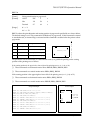
C
2, 50
Paper feed direction
Print Direction
D
n
The parameters for the horizontal or vertical motion units (x or y) differ depending on the starting
position of the printing area as follows:
If the starting position is the upper left or lower right of the printing area (n = 0, 2, 48, or 50):
❏
These commands use horizontal motion units: ESC SP, ESC $, ESC W, ESC \
❏
These commands use vertical motion units: ESC 3, ESC J, ESC W
If the starting position is the upper right or lower left of the printing area (n = 1, 3, 49, or 51):
❏
These commands use horizontal motion units: ESC 3, ESC J, ESC W
❏
These commands use vertical motion units: ESC SP, ESC $, ESC W, ESC \
Program Example
Rev. A
CCCCC
DDDDD
AAAAA
BBBBB
← Printing
area set
by ESC W
EEEEE
PRINT #1, CHR$(&H1B);"L";← Select page mode
PRINT #1, CHR$(&H1B);"W";CHR$(0);CHR$(0);CHR$(0);CHR$(0);
CHR$(100);CHR$(0);CHR$(100);CHR$(0);
PRINT #1, CHR$(&H1B);"T";CHR$(0);
PRINT #1, "AAAAA"; CHR$(&HA);← Store characters for printing
PRINT #1, "BBBBB"; CHR$(&HA);← Store characters for printing
PRINT #1, CHR$(&H1B);"T";CHR$(1);
PRINT #1, "CCCCC"; CHR$(&HA);← Store characters for printing
PRINT #1, "DDDDD"; CHR$(&HA);← Store characters for printing
PRINT #1, CHR$(&H1B);"T";CHR$(2);
PRINT #1, "EEEEE"; CHR$(&HC);← Batch print
Print Sample
Command Descriptions 1-29
Bit-Image Commands
The TM-U375/U375P supports the following bit-image commands:
Command
Name
ESC ✻
Select bit-image mode
GS ✻
Define downloaded bit image
GS /
Print downloaded bit image
ESC ✻ m nL nH d1 ... dk
[Name]
Select bit-image mode
[Format]
ASCII
ESC
✻
m
nL
nH
d1 ... dk
Hex
1B
2A
m
nL
nH
d1 ... dk
Decimal
27
42
m
nL
nH
d1 ... dk
[Range]
m = 0, 1
0 ≤ nL ≤ 255
0 ≤ nH ≤ 3
0 ≤ d ≤ 255
ESC ✻ m nL nH d1 ... dk selects a bit-image mode using m for the number of dots specified by
(n L + nH × 256). This command is used to print a predefined picture or logo. The modes selectable by
m are as follows:
Vertical Direction
m
Mode
Horizontal Direction
Number of
Dots
Dot Density
(DPI)
Dot Density
(DPI)
Total Dots in
Standard Mode
0
8-dot single-density
8
72
80
200
1
8-dot double-density
8
72
160
400
Program Example
m=0:
m=1:
END
Print Sample
GOSUB bitimage8
GOSUB bitimage8
m=0
m=1
bitimage8:
PRINT #1, CHR$(&H1B);"*";CHR$(m);CHR$(180);CHR$(0);
FOR i=1 TO 180
PRINT #1, CHR$(i);
NEXT i
PRINT #1, CHR$(&HA);
RETURN
1-30 Command Descriptions
Rev. A
TM–U375/U375P Information Manual
GS ✻ x y d1 ... d(x × y × 8)
[Name]
Define downloaded bit image
[Format]
ASCII
GS
✻
x
y
d1 ... d(x × y × 8)
Hex
1D
2A
x
y
d1 ... d(x × y × 8)
Decimal
29
42
x
y
d1 ... d(x × y × 8)
[Range]
1 ≤ x ≤ 255
1 ≤ y ≤ 255
x × y ≤ 512
0 ≤ d ≤ 255
GS / m
[Name]
Print downloaded bit image
[Format]
ASCII
GS
/
m
Hex
1D
2F
m
Decimal
29
47
m
[Range]
0≤m≤1
48 ≤ m ≤ 49
GS ✻ x y d1 ... d(x × y × 8) defines a downloaded bit image using x × 8 dots in the horizontal direction
and y × 8 dots in the vertical direction. Once a downloaded bit image has been defined, it is available
until another definition is made; ESC @ or ESC & is executed; the printer is reset; or the power is
turned off. When this command is executed, the user-defined characters are cleared. The default
setting is no downloaded bit image defined.
GS / m prints a downloaded bit image using the mode specified by m as follows. In standard mode,
this command is effective only when there is no data in the print buffer. In page mode, doubledensity mode is disabled. This command is ignored if a downloaded bit image has not been defined.
m
Mode
Horizontal Dot Density
Set Adjacent Dots
0, 48
Normal
Double
Prohibited
1, 49
Double width
Single
Permitted
Rev. A
Command Descriptions 1-31
Program Example
Program Example (continued)
x=16: y=5
PRINT #1, CHR$(&H1D);"*";CHR$(x);CHR$(y);
FOR i=1 TO x*y*8
READ a$: d=VAL("&H"+a$)
PRINT #1, CHR$(d);
NEXT i
FOR m=0 TO 1
PRINT #1, CHR$(&H1D);"/";CHR$(m)
PRINT #1, CHR$(&HA);
NEXT m
END
DATA
DATA
DATA
DATA
DATA
DATA
DATA
DATA
DATA
DATA
DATA
DATA
DATA
DATA
DATA
DATA
DATA
DATA
DATA
DATA
DATA
Define
downloaded
bit image
← Print downloaded
bit image
FF,FF,FF,FF,FF,FF,FF,FF,FF,FF,C0,00,00,00,03,C0
00,00,00,03,CF,FF,FF,FF,F3,CF,FF,FF,FF,F3,CF,FF
FF,FF,F3,CF,FF,FF,FF,F3,CF,FF,FF,FF,F3,CF,C0,FC
03,F3,CF,C0,FC,03,F3,CF,C0,FC,03,F3,CF,C0,FC,03
F3,CF,C0,FC,03,F3,CF,C0,FC,03,F3,CF,C0,FC,03,F3
CF,C0,FC,03,F3,CF,C0,FC,03,F3,CF,C0,00,03,F3,C0
00,00,00,03,C0,FF,00,03,F3,C3,FF,C0,03,F3,C7,FF
E0,03,F3,C7,FF,F0,03,F3,CF,FF,F8,03,F3,CF,FF,FC
03,F3,CF,E3,FE,03,F3,CF,C1,FF,03,F3,CF,C0,FF,83
F3,CF,C0,7F,C7,F3,CF,C0,3F,FF,F3,CF,C0,1F,FF,F3
CF,C0,0F,FF,E3,CF,C0,07,FF,E3,CF,C0,03,FF,C3,C0
00,00,FF,03,C0,00,00,00,03,C0,3F,FF,FC,03,C0,FF
FF,FF,03,C3,FF,FF,FF,C3,C7,FF,FF,FF,E3,C7,FF,FF
FF,E3,CF,FF,FF,FF,F3,CF,F0,00,0F,F3,CF,C0,00,03
F3,CF,C0,00,03,F3,CF,C0,00,03,F3,CF,C0,00,03,F3
CF,C0,00,03,F3,CF,C0,00,03,F3,CF,C0,00,03,F3,CF
C0,00,03,F3,CF,C0,00,03,F3,C0,00,00,00,03,C0,00
00,00,73,C0,00,00,03,C3,C0,00,00,1E,03,C0,00,00
70,03,C0,00,03,C0,03,C0,00,1E,00,03,C0,00,78,00
03,C0,03,C0,00,03,C0,0E,00,00,03,C0,78,00,00,03
C3,C0,00,00,03,CE,00,00,00,03,C0,00,00,00,03,CF
DATA
DATA
DATA
DATA
DATA
DATA
DATA
DATA
DATA
DATA
DATA
DATA
DATA
DATA
DATA
DATA
DATA
DATA
DATA
FF,FF,FF,F3,CF,FF,FF,FF,F3,CF,FF,FF,FF,F3,CF,FF
FF,FF,F3,CF,FF,FF,FF,F3,CF,FF,FF,FF,F3,CF,C0,0F
C0,03,CF,C0,0F,C0,03,CF,C0,0F,C0,03,CF,C0,0F,C0
03,CF,C0,0F,C0,03,CF,E0,1F,C0,03,CF,FF,FF,C0,03
CF,FF,FF,CO,03,C7,FF,FF,80,03,C7,FF,FF,80,03,C1
FF,FE,00,03,C0,3F,F0,00,03,C0,00,00,00,03,C0,0F
FF,F0,03,C0,FF,FF,FF,03,C3,FF,FF,FF,C3,C7,FF,FF
FF,E3,C7,FF,FF,FF,E3,CF,FF,FF,FF,F3,CF,F0,00,0F
F3,CF,C0,00,03,F3,CF,C0,00,03,F3,CF,C0,00,03,F3
CF,C0,00,03,F3,CF,C0,00,03,F3,CF,C0,00,03,F3,CF
C0,00,03,F3,CF,F0,00,0F,F3,CF,FF,FF,FF,F3,C7,FF
FF,FF,E3,C7,FF,FF,FF,E3,C3,FF,FF,FF,C3,C0,FF,FF
FF,03,C0,0F,FF,F0,03,C0,00,00,00,03,C0,FF,00,03
F3,C3,FF,C0,03,F3,C7,FF,E0,03,F3,C7,FF,F0,03,F3
CF,FF,F8,03,F3,CF,FF,FC,03,F3,CF,E3,FE,03,F3,CF
C1,FF,03,F3,CF,C0,FF,83,F3,CF,C0,7F,C7,F3,CF,C0
3F,FF,F3,CF,C0,1F,FF,F3,CF,C0,0F,FF,E3,CF,C0,07
FF,E3,CF,C0,03,FF,C3,C0,00,00,FF,C3,C0,00,00,00
03,C0,00,00,00,03,FF,FF,FF,FF,FF,FF,FF,FF,FF,FF
Print Sample
← GS / 0
← GS / 1
Status Commands
The TM-U375/U375P supports the following status transmission commands. These commands can
be used to determine the status of the printer, paper sensors, and peripheral devices connected to the
printer.
Command
Name
GS a
Enable/disable Automatic Status Back (ASB)
GS r
Transmit status
DLE EOT
Real-time status transmission
ESC u
Transmit peripheral device status
ESC v
Transmit paper sensor status
1-32 Command Descriptions
Rev. A
TM–U375/U375P Information Manual
GS a n
[Name]
Enable/disable Automatic Status Back (ASB)
[Format]
ASCII
GS
a
n
Hex
1D
61
n
Decimal
29
97
n
0 ≤ n ≤ 255
[Range]
GS a n selects a status for ASB transmission. ASB is enabled if any status item is selected. The printer
automatically transmits a 4-byte status message whenever the status changes. Multiple status items
can be selected. When n=0, ASB is disabled. The default (n=0 or 2) depends on the DIP switch
settings. If ASB is enabled when the printer is disabled by the ESC = command, the printer transmits
a 4-byte status message whenever the status changes. The status items are selected using n as follows:
Bit
Off/On
Hex
Decimal
Function
Off
00
0
Drawer kick-out connector pin 3 status disabled.
On
01
1
Drawer kick-out connector pin 3 status enabled.
Off
00
0
On-line/off-line status disabled.
On
02
2
On-line/off-line status enabled.
Off
00
0
Error status disabled.
On
04
4
Error status enabled.
Off
00
0
Paper roll sensor status disabled.
On
08
8
Paper roll sensor status enabled.
—
—
—
Undefined.
Off
00
0
Cut-sheet (slip or validation) sensor and status disabled.
On
20
32
Cut-sheet (slip or validation) sensor and status enabled.
—
—
—
Undefined.
0
1
2
3
4
5
6, 7
Program Example
PRINT #1, CHR$(&H1D);"a";CHR$(4); ←
Enable "Error" status
First byte (printer information)
Bit
Off/On
Hex
Decimal
Status for ASB
0
Off
00
0
Not used. Fixed to Off.
1
Off
00
0
Not used. Fixed to Off.
Off
00
0
Drawer kick-out connector pin 3 is LOW.
On
04
4
Drawer kick-out connector pin 3 is HIGH.
2
Rev. A
Command Descriptions 1-33
Bit
Off/On
Hex
Decimal
Status for ASB
Off
00
0
On-line.
On
08
8
Off-line.
On
10
16
Not used. Fixed to On.
Off
00
0
Cover closed.
On
20
32
Cover open.
Off
00
0
Paper is not being fed by the paper feed
button.
On
40
64
Paper is being fed by the paper feed button.
Off
00
0
Not used. Fixed to Off.
3
4
5
6
7
Second byte (printer information)
Bit
Off/On
Hex
Decimal
Status for ASB
0, 1
—
—
—
Undefined.
Off
00
0
No mechanical error.
On
04
4
Mechanical error occurred.
3
—
—
—
Undefined.
4
Off
00
0
Not used. Fixed to Off.
Off
00
0
No unrecoverable error.
On
20
32
Unrecoverable error occurred.
Off
00
0
No automatically recoverable error.
On
40
64
Automatically recoverable error occurred.
Off
00
0
Not used. Fixed to Off.
2
5
6
7
Third byte (paper sensor information)
Bit
Off/On
Hex
Decimal
Status for ASB
Off
00
0
Paper roll near-end sensor: paper adequate.
On
03
3
Paper roll near-end sensor: paper near end.
2, 3
—
—
—
Undefined.
4
Off
00
0
Not used. Fixed to Off.
Off
00
0
Cut-sheet sensor: slip or validation paper present.
On
60
96
Cut-sheet sensor: slip or validation paper not present.
Off
00
0
Not used. Fixed to Off.
0, 1
5, 6
7
1-34 Command Descriptions
Rev. A
TM–U375/U375P Information Manual
Fourth byte (paper sensor information)
Bit
Off/On
Hex
Decimal
Status for ASB
Off
00
0
Slip paper selected.
On
01
1
Slip paper not selected.
Off
00
0
Slip paper status: possible to print.
On
02
2
Slip paper status: not possible to print.
Off
00
0
Validation paper selected.
On
04
4
Validation paper not selected.
Off
00
0
Validation paper status: possible to print.
On
08
8
Validation paper status: not possible to print.
Off
00
0
Not used. Fixed to Off.
Off
00
0
Cut-sheet sensor: slip or validation paper present.
On
60
96
Cut-sheet sensor: slip or validation paper not present.
Off
00
0
Not used. Fixed to Off.
0
1
2
3
4
5, 6
7
GS r n
[Name]
Transmit status
[Format]
ASCII
GS
r
n
Hex
1D
72
n
Decimal
29
114
n
[Range]
1≤n≤3
49 ≤ n ≤ 51
GS r n transmits 1 byte of status data specified by n as follows: paper sensor status when n=1 or 49, drawer
kick-out connector status when n=2 or 50, and cut-sheet (slip or validation paper) status when n=3 or 51.
Program Example
PRINT #1, CHR$(&H1D);"r";CHR$(1); ←
Transmits paper sensor status
Paper sensor status (n=1, 49)
Bit
Off/On
Hex
Decimal
Status
Off
00
0
Paper roll near-end sensor: paper adequate.
On
03
3
Paper roll near-end sensor: paper near end.
2, 3
—
—
—
Undefined.
4
Off
00
0
Not used. Fixed to Off.
Off
00
0
Cut-sheet sensor: slip or validation paper present.
On
60
96
Cut-sheet sensor: slip or validation paper not present.
Off
00
0
Not used. Fixed to Off.
0, 1
5, 6
7
Rev. A
Command Descriptions 1-35
Drawer kick-out connector status (n=2, 50)
Bit
Off/On
Hex
Decimal
Status
Off
00
0
Drawer kick-out connector pin 3 is LOW.
On
01
1
Drawer kick-out connector pin 3 is HIGH.
1-3
—
—
—
Undefined.
4
Off
00
0
Not used. Fixed to Off.
5, 6
—
—
—
Undefined.
7
Off
00
0
Not used. Fixed to Off.
0
Cut-sheet (slip or validation paper) status (n=3, 51)
Transmits the values 00H - 0FH, indicating the remaining printable area as follows:
Number of
Remaining Dots
Cut- Sheet Status
Hex
Decimal
0-8
00H
0
9 - 17
01H
1
18 - 26
•
•
•
117 - 125
02H
•
•
•
0DH
2
•
•
•
13
126 - 134
0EH
14
135 and up
0FH
15
DLE EOT n
[Name]
Real-time status transmission
[Format]
ASCII
DLE
EOT
n
Hex
10
04
n
Decimal
16
4
n
[Range]
1≤n≤6
DLE EOT n transmits the specified status in real time. This command is executed even when the
printer is off-line, the print buffer is full, or an error occurs. n indicates the status function as follows:
n
Function
1
Transmit printer status
2
Transmit off-line status
3
Transmit error status
4
Transmit paper roll sensor status
1-36 Command Descriptions
Rev. A
TM–U375/U375P Information Manual
n
Function
5
Transmit slip paper status
6
Transmit validation paper status
Program Example
PRINT #1, CHR$(&H10);CHR$(&H4);CHR$(2); ← Transmits
off-line status
Printer status (n=1)
Bit
Off/On
Hex
Decimal
Status
0
Off
00
0
Not used. Fixed to Off.
1
On
02
2
Not used. Fixed to On.
Off
00
0
Drawer kick-out connector pin 3 is LOW.
On
04
4
Drawer kick-out connector pin 3 is HIGH.
Off
00
0
On-line.
On
08
8
Off-line.
4
On
10
16
Not used. Fixed to On.
5, 6
—
—
—
Undefined.
7
Off
00
0
Not used. Fixed to Off.
2
3
Off-line status (n=2)
Bit
Off/On
Hex
Decimal
Status
0
Off
00
0
Not used. Fixed to Off.
1
On
02
2
Not used. Fixed to On.
Off
00
0
Cover is closed.
On
04
4
Cover is open.
Off
00
0
Paper is not being fed by the paper feed button.
On
08
8
Paper is being fed by the paper feed button.
On
10
16
Not used. Fixed to On.
Off
00
0
No paper-end stop.
On
20
32
Printing stops due to paper-end.
Off
00
0
No error.
On
40
64
Error occurred.
Off
00
0
Not used. Fixed to Off.
2
3
4
5
6
7
Rev. A
Command Descriptions 1-37
Error status (n=3)
Bit
Off/On
Hex
Decimal
Status
0
Off
00
0
Not used. Fixed to Off.
1
On
02
2
Not used. Fixed to On.
Off
00
0
No mechanical error.
On
04
4
Mechanical error occurred.
3
—
—
—
Undefined.
4
On
10
16
Not used. Fixed to On.
Off
00
0
No unrecoverable error.
On
20
32
Unrecoverable error occurred.
Off
00
0
No automatically recoverable error.
On
40
64
Automatically recoverable error occurred.
Off
00
0
Not used. Fixed to Off.
2
5
6
7
Paper roll sensor status (n=4)
Bit
Off/On
Hex
Decimal
Status
0
Off
00
0
Not used. Fixed to Off.
1
On
02
2
Not used. Fixed to On.
Off
00
0
Paper roll near-end sensor: paper adequate.
On
0C
12
Paper roll near-end sensor: paper near end.
4
On
10
16
Not used. Fixed to On.
5, 6
—
—
—
Undefined.
7
Off
00
0
Not used. Fixed to Off.
2, 3
Slip paper status (n=5)
Bit
Off/On
Hex
Decimal
Status
0
Off
00
0
Not used. Fixed to Off.
1
On
02
2
Not used. Fixed to On.
Off
00
0
Slip paper selected.
On
04
4
Slip paper not selected.
Off
00
0
Does not wait for slip paper insertion.
On
08
8
Waits for slip paper insertion.
On
10
16
Not used. Fixed to On.
Off
00
0
Cut-sheet sensor: slip or validation paper present.
On
60
96
Cut-sheet sensor: slip or validation paper not persent.
Off
00
0
Not used. Fixed to Off.
2
3
4
5, 6
7
1-38 Command Descriptions
Rev. A
TM–U375/U375P Information Manual
Validation paper status (n=6)
Bit
Off/On
Hex
Decimal
Status
0
Off
00
0
Not used. Fixed to Off.
1
On
02
2
Not used. Fixed to On.
Off
00
0
Validation paper selected.
On
04
4
Validation paper not selected.
Off
00
0
Does not wait for validation paper insertion.
On
08
8
Waits for validation paper insertion.
On
10
16
Not used. Fixed to On.
Off
00
0
Cut-sheet sensor: slip or validation paper present.
On
60
96
Cut-sheet sensor: slip or validation paper not persent.
Off
00
0
Not used. Fixed to Off.
2
3
4
5, 6
7
ESC u n
[Name]
Transmit peripheral device status
[Format]
ASCII
ESC
u
n
Hex
1B
75
n
Decimal
27
117
n
[Range]
n = 0, 48
ESC u n transmits the status of drawer kick-out connector pin 3 as 1 byte of data when n=0 or 48. This
command allows the host to determine the status of a peripheral device. GS r is preferred for
checking the status because ESC u is not a recommended command. The status to be transmitted is
shown in the table below.
Program Example
PRINT #1, CHR$(&H1B);"p";CHR$(0);CHR$(25);CHR$(250); ← Generates
PRINT #1, CHR$(&H1B);"u";CHR$(0);
a pulse
Peripheral device status
Bit
Off/On
Hex
Decimal
Status
Off
00
0
Drawer kick-out connector pin 3 is LOW.
On
01
1
Drawer kick-out connector pin 3 is HIGH.
1-3
—
—
—
Undefined.
4
Off
00
0
Not used. Fixed to Off.
5, 6
—
—
—
Undefined.
7
Off
00
0
Not used. Fixed to Off.
0
Rev. A
Command Descriptions 1-39
ESC v
[Name]
Transmit paper sensor status
[Format]
ASCII
ESC
v
Hex
1B
76
Decimal
27
118
ESC v transmits the status of a paper sensor as 1 byte of data. GS r is preferred for checking the
status because ESC v is not a recommended command. The status to be transmitted is shown in the
table below.
Program Example
PRINT #1, CHR$(&H1B);"v";
Paper sensor status
Bit
Off/On
Hex
Decimal
Status
Off
00
0
Paper roll near-end sensor: paper adequate.
On
03
3
Paper roll near-end sensor: paper near end.
2, 3
—
—
—
Undefined.
4
Off
00
0
Not used. Fixed to Off.
Off
00
0
Cut-sheet sensor: slip or validation paper present.
On
60
96
Cut-sheet sensor: slip or validation paper not present.
Off
00
0
Not used. Fixed to Off.
0, 1
5, 6
7
Mechanism Control Commands
The TM-U375/U375P supports the following mechanism control commands:
Command
Name
ESC <
Return home
ESC U
Turn unidirectional printing mode on/off
ESC q
Paper release
ESC <
[Name]
Return home
[Format]
ASCII
ESC
<
Hex
1B
3C
Decimal
27
60
1-40 Command Descriptions
Rev. A
TM–U375/U375P Information Manual
ESC < moves the print head to the home position. The print head first moves to the left-most position,
then to the right-most position, and then to approximately the center of the line.
To prevent paper jams, do not use this command while slip paper is inserted.
Program Example
PRINT #1, CHR$(&H1B);"<";
ESC U n
[Name]
Turn unidirectional printing mode on/off
[Format]
ASCII
ESC
U
n
Hex
1B
55
n
Decimal
27
85
n
[Range]
0 ≤ n ≤ 255
ESC U n turns unidirectional printing mode on or off. When the LSB (least significant bit) of n is 1,
unidirectional printing is turned on; when it is 0, unidirectional printing is turned off and
bidirectional printing mode is turned on. Unidirectional printing can be turned on when printing
double-height characters to ensure that the top and bottom of the characters are aligned. The default
setting is n=0 in standard mode and n=1 in page mode.
Program Example
PRINT #1, CHR$(&H1B);"U";CHR$(1); ←
Unidirectional printing mode turned on
ESC q
[Name]
Paper release
[Format]
ASCII
ESC
q
Hex
1B
71
Decimal
27
113
ESC q releases the paper.
Program Example
PRINT #1, CHR$(&H1B);"q"
Rev. A
Command Descriptions 1-41
Miscellaneous Function Commands
The TM-U375/U375P supports the following miscellaneous function commands:
Command
Name
GS P
Set horizontal and vertical motion units
ESC @
Initialize printer
GS E
Select head control method
GS I
Transmit printer ID
ESC p
Generate pulse
ESC =
Select peripheral device
ESC L
Select page mode
DLE ENQ
Real-time request to printer
GS P x y
[Name]
Set horizontal and vertical motion units
[Format]
ASCII
GS
P
x
y
Hex
1D
50
x
y
Decimal
29
80
x
y
[Range]
0 ≤ x ≤ 255
0 ≤ y ≤ 255
GS P x y sets the horizontal and vertical motion units to 1/x and 1/y inches, respectively. The
horizontal and vertical motion units indicate the minimum pitch used for calculating the values of
related commands (shown below). The default values are x=160 and y=144. The calculated result
when using this command with other commands is truncated to the minimum value of the
mechanical pitch (1/160 inch horizontal and 1/144 inch vertical) or an exact multiple of that
minimum value. When x and y are set to 0, the default setting of each value is used.
Commands used with the horizontal motion unit (1/x) in standard mode: ESC SP, ESC $, ESC W,
ESC /, GS L, and GS W.
Commands used with the vertical motion unit (1/y ) in standard mode: ESC 3, ESC J, and ESC W.
1-42 Command Descriptions
Rev. A
TM–U375/U375P Information Manual
Commands used with the horizontal and vertical motion units (1/x and 1/y) in page mode (either x
or y can be used, depending on the print direction set with ESC T): ESC SP, ESC $, ESC 3, ESC J,
ESC W, and ESC \.
Program Example
PRINT
PRINT
PRINT
PRINT
PRINT
PRINT
PRINT
PRINT
PRINT
#1,
#1,
#1,
#1,
#1,
#1,
#1,
#1,
#1,
Print Sample
CHR$(&H1D);"P";CHR$(180);CHR$(180);
CHR$(&H1B);"3";CHR$(30); ← Set line spacing
"AAAAA"; CHR$(&HA);
"BBBBB"; CHR$(&HA);
CHR$(&H1D);"P";CHR$(180);CHR$(90);
CHR$(&H1B);"3";CHR$(30); ← Set line spacing
"CCCCC"; CHR$(&HA);
"DDDDD"; CHR$(&HA);
"EEEEE"; CHR$(&HA);
AAAAA
BBBBB
CCCCC
30/180-inch line spacing
DDDDD
30/90-inch line spacing
EEEEE
ESC @
[Name]
Initialize printer
[Format]
ASCII
ESC
@
Hex
1B
40
Decimal
27
64
ESC @ initializes the printer. All settings, including character font and line spacing settings, are
canceled. The data in the print buffer is cleared, and the printer mode is reset to the mode that was in
effect when the power was turned on. The DIP switch settings are not checked again, and the data in
the receive buffer is not cleared.
Program Example
PRINT
PRINT
PRINT
PRINT
#1,
#1,
#1,
#1,
Print Sample
CHR$(&H1B);"!";CHR$(56);
"AAAAA"; CHR$(&HA);
CHR$(&H1B);"@";
"BBBBB"; CHR$(&HA);
AAAAA
BBBBB ← All
settings are canceled after ESC @ is executed
GS E n
[Name]
Select head control method
[Format]
ASCII
GS
E
n
Hex
1D
45
n
Decimal
29
69
n
[Range]
Rev. A
0 ≤ n ≤ 255
Command Descriptions 1-43
GS E n selects the head energizing time corresponding to the paper type selected by ESC c 0. The
default settings are Standard (n=1) when the paper roll is selected and Copy (n=0) when a cut sheet
(slip or validation paper) is selected. Independent settings can be used for each paper type. In
standard mode, this command is enabled only when input at the beginning of a line. The bit value of
n is used as follows:
Bit
Off/On
Hex
Decimal
Function
Off
00
0
Head energizing time: Copy.
On
01
1
Head energizing time: Standard.
—
—
—
Undefined.
0
1-7
Program Example
PRINT #1,CHR$(&H1B);"c0";CHR$(1);← Select
PRINT #1,CHR$(&H1D);"E";CHR$(0); ← Select
paper roll
copy mode
GS I n
[Name]
Transmit printer ID
[Format]
ASCII
GS
I
n
Hex
1D
49
n
Decimal
29
73
n
1≤n≤3
[Range]
49 ≤ n ≤ 51
GS I n transmits the printer ID specified by n as follows. Each printer ID consists of 1 byte of data.
n
Printer ID
Specification
ID (hexadecimal)
1, 49
Printer model ID
TM-U375/U375P
0AH
2, 50
Type ID
See table below.
3, 51
ROM version ID
Depends on ROM version.
Type ID (n=2 or 50)
Bit
Off/On
Hex
Decimal
Function
0
Off
00
0
Two-byte character code not supported.
1
On
00
0
No auto-cutter equipped.
Off
00
0
Not customer display equipped (DIP switch 2-1 is Off).
On
04
4
Customer display equipped (DIP switch 2-1 is On).
3
—
—
—
Undefined.
4
Off
00
0
Not used. Fixed to Off.
5, 6
—
—
—
Undefined.
7
Off
00
0
Not used. Fixed to Off.
2
1-44 Command Descriptions
Rev. A
TM–U375/U375P Information Manual
Program Example
PRINT #1, CHR$(&H1D);"I";CHR$(1);← Transmits
printer ID
ESC p m t1 t2
[Name]
Generate pulse
[Format]
ASCII
ESC
p
m
t1
t2
Hex
1B
70
m
t1
t2
Decimal
27
112
m
t1
t2
[Range]
m = 0, 1, 48, 49
0 ≤ t1 ≤ 255
0 ≤ t2 ≤ 255
ESC p m t1 t2 sends a pulse (on time= t1 × 2 msec / off time= t2 × 2 msec) to the specified connector
pin. When m=0 or 48, the pulse is sent to drawer kick-out connector pin 2; when m=1 or 49, the pulse
is sent to drawer kick-out connector pin 5.
Program Example
PRINT #1, CHR$(&H1B);"p";CHR$(0);CHR$(25);CHR$(250);
ESC = n
[Name]
Select peripheral device
[Format]
ASCII
ESC
=
n
Hex
1B
3D
n
Decimal
27
61
n
[Range]
1≤n≤3
ESC = n selects the device to which the host computer sends data, based on the value of n as follows:
When the printer is disabled (n=2), it ignores all received data with the exception of the DLE ENQ 1
and DLE ENQ 2 commands. The default setting varies according to the DIP switch settings.
n
Peripheral Device Status
1
Only printer selected.
2
Only customer display selected.
3
Both printer and customer display selected.
Rev. A
Command Descriptions 1-45
Program Example
Display Sample
AAAAA_
PRINT
PRINT
PRINT
PRINT
PRINT
PRINT
#1,
#1,
#1,
#1,
#1,
#1,
CHR$(&H1B);"=";CHR$(2);←
"AAAAA";
CHR$(&H1B);"=";CHR$(1);←
" BBBBB";
CHR$(&H1B);"=";CHR$(3);←
" CCCCC"; CHR$(&HA);
Customer display
selected
↓
Printer selected
Selects only the printer
AAAAA_
Both printer and
customer display
selected
↓
Selects both the printer and
the customer display
AAAAA CCCCC_
Print Sample
BBBBB CCCCC
ESC L
[Name]
Select page mode
[Format]
ASCII
ESC
L
Hex
1B
4C
Decimal
27
76
ESC L switches from standard mode to page mode. This command is enabled only when input at the
beginning of a line in standard mode; it has no effect in page mode. Standard mode is selected as the
default. When FF or ESC @ is entered in page mode, the printer returns to standard mode.
Program Example
Print Sample
PRINT #1, CHR$(&H1B);"L";← Select page mode
PRINT #1, CHR$(&H1B);"W";CHR$(0);CHR$(0);CHR$(0);
CHR$(0);CHR$(50);CHR$(0);CHR$(50);CHR$(0);
PRINT #1, CHR$(&H1B);"T";CHR$(0);
PRINT #1, "AAAAA"; CHR$(&HA);← Store characters for printing
PRINT #1, "BBBBB"; CHR$(&HA);← Store characters for printing
PRINT #1, "CCCCC"; CHR$(&HC);← Batch print
AAAAA
BBBBB
CCCCC
DLE ENQ n
[Name]
Real-time request to printer
[Format]
ASCII
DLE
ENQ
n
Hex
10
05
n
Decimal
16
5
n
[Range]
1≤n≤3
1-46 Command Descriptions
Rev. A
TM–U375/U375P Information Manual
DLE ENQ n responds to a request in real time from the host computer, specified by n as shown
below. This command is executed even when the printer is off-line, the receive buffer is full, or an
error occurs. It is valid only when n=1 or n=2, or when a recoverable error other than an
automatically recoverable error occurs. When n=3, it is valid only when the printer is waiting for a
cut sheet (slip or validation paper).
n
Request
1
Restarts printing from the beginning of the line where an
error occurred, after recovering from the error.
2
Recovers from an error after clearing the receive and print
buffers.
3
Cancels cut-sheet waiting status.
Program Example
PRINT #1, CHR$(&H10);CHR$(&H5);CHR$(3);
Rev. A
Command Descriptions 1-47
Character Code Tables
SP in a table represents space. Refer to page 1-51 for information on how to read these tables.
Page 0 (PC437: U.S.A., Standard Europe) (International character set: U.S.A)
Page 1 (Katakana)
1-48 Command Descriptions
Rev. A
TM–U375/U375P Information Manual
Page 2 (PC850: Multilingual)
Page 3 (PC860: Portuguese)
Rev. A
Command Descriptions 1-49
Page 4 (PC863: Canadian-French)
Page 5 (PC865: Nordic)
1-50 Command Descriptions
Rev. A
TM–U375/U375P Information Manual
International character set
ASCII code
Country
Hex
23
24
40
5B
5C
5D
5E
60
7B
7C
7D
7E
Dec
35
36
64
91
92
93
94
96
123
124
125
126
U.S.A.
#
$
@
[
\
]
^
`
{
¦
}
~
France
#
$
à
°
ç
§
^
`
é
ù
è
¨
Germany
#
$
§
Ä
Ö
Ü
^
`
ä
ö
ü
ß
U.K.
£
$
@
[
\
]
^
`
{
¦
}
~
Denmark I
#
$
@
Æ
Ø
Å
^
`
æ
ø
å
~
Sweden
#
¤
É
Ä
Ö
Å
Ü
é
ä
ö
å
ü
Italy
#
$
@
°
\
é
^
ù
à
ò
è
ì
Spain
Pt
$
@
¡
Ñ
¿
^
`
¨
ñ
}
~
Japan
#
$
@
[
¥
]
^
`
{
¦
}
~
Norway
#
¤
É
Æ
Ø
Å
Ü
é
æ
ø
å
ü
Denmark II
#
$
É
Æ
Ø
Å
Ü
é
æ
ø
å
ü
Using the Character Code Tables
The example below uses Page 0 (PC437) (see page 1-48) to illustrate the use of the character code
tables.
You can find the character "A" in Page 0 as follows:
The decimal value for the character "A" is 65.
Follow its column straight up to find the digits.
Hexadecimal .....4
Binary .................0100
These numbers are the most significant bits of the ASCII code.
Follow its row to the left to find the digits.
Hexadecimal .....1
Binary .................0001
These numbers are the least significant bits of the ASCII code.
The combination of the numbers above is the ASCII code for the character "A".
Decimal ..............65
Hexadecimal .....41
Binary .................01000001
Rev. A
Command Descriptions 1-51
TM–U375/U375P Information Manual
Chapter 2
Application
This chapter presents an example illustrating ESC/POS command functions and printing results. The
example shows procedures and a program for combining system processes with the TM-U375,
DM-D202II, and a drawer.
System Processing and Procedures
Procedure
Commands Used
Description
1. Define stamp data
GS ✻
Defines a downloaded bit image to be used as a stamp.
2. Stamp
ESC =, ESC c 0, ESC a, GS /,
ESC J
Prints the specified stamp (downloaded bit image) in the
center of the receipt at the print position defined by ESC a.
3. Display a message
ESC =
Selects only the customer display using ESC =. Displays a
message and the time.
4. Print date and time
ESC =, ESC d
Selects only the printer using ESC =. Selects left justification
after printing the date and time in the center of the
receipt.
5. Print item A
Display item A
ESC a, ESC =, ESC !, LF
Selects both the printer and customer display using ESC =.
Prints and displays item A.
6. Print item B
Display item B
ESC =, ESC !, LF, ESC p, ESC d
Selects only the printer using ESC = and prints item B.
Displays the amount paid only on the customer display.
7. Display the amount of
change and a message
ESC =
Selects only the customer display using ESC = and displays
the amount of change and a message.
8. Stamp
ESC =, ESC a, GS /, ESC J
Prints the stamp (downloaded bit image) for the next
receipt and advances the paper to the cut position.
Uses the manual cutter to cut the paper.
Print Sample
YOUR RECEIPT
Stamp
Thank you
MARCH 1, 1996, 10:30
96.0
15.0
TM-U375
PS-150
Item A
111.0
TOTAL
----------------------------------------120.0
PAID
9.0
CHANGE
Item B
-----------------------------------------
Cut (manual cut)
YOUR RECEIPT
Stamp for the next receipt
Thank you
Rev. A
Application 2-1
Display Sample
Define data
1
Scroll the message and display
the counter
WELCOME
2
1 0 : 30 : 0 0
3
Display Item A
TM—U375
9 6. 0
4
PS—150
Display Item A
15.0
5
Display total
TOTAL
1 1 1. 0
6
Display amount paid
PAID
120.0
CHANGE
>> >> T h a n k Y o u
2-2 Application
9. 0
Display change amount
>> >>
7
Rev. A
TM–U375/U375P Information Manual
Program Example
PRINT #1, CHR$(&H1B);"=";CHR$(3);
← Selects peripheral devices (printer and customer
PRINT #1, CHR$(&H1B);"@";
← Initializes the devices
PRINT #1, CHR$(&H1B);"t";CHR$(1);
← Selects the character code table (page 1)
PRINT #1, CHR$(&H1B);"=";CHR$(1);
← Selects peripheral device (printer)
PRINT #1, CHR$(&H1D);"*";CHR$(40);CHR$(6)
FOR I=1 TO 1920
READ a$: PRINT #1, CHR$(VAL("&H"+a$));
NEXT I
GOSUB stamp
PRINT
PRINT
PRINT
PRINT
PRINT
#1,
#1,
#1,
#1,
#1,
←
display)
Prints stamp data
CHR$(&H1B);"=";CHR$(2);
← Selects peripheral device (customer display)
CHR$(&HC);
← Clears customer display screen
CHR$(229);CHR$(230);CHR$(229);"
WELCOME
";
CHR$(229);CHR$(230);CHR$(229);
CHR$(&H1F);"T";CHR$(10);CHR$(30);
← Sets and displays a counter (time)
W$=INPUT$(1)
PRINT #1, CHR$(&HC);
PRINT #1, CHR$(&H1B);"=";CHR$(1);
PRINT #1, "MARCH 1, 1996, 10:30";
PRINT #1, CHR$(&H1B);"d";CHR$(3);
←
←
←
PRINT #1, CHR$(&H1B);"a";CHR$(0);
PRINT #1, CHR$(&H1B);"!";CHR$(1);
PRINT #1, CHR$(&H1B);"=";CHR$(3);
PRINT #1, "TM-U375
W$=INPUT$(1)
PRINT #1, "PS-150
←
Selects print position (left justification)
←
Selects peripheral devices (printer and customer display)
←
Waits for input
W$=INPUT$(1)
PRINT #1, CHR$(&H1B);"=";CHR$(1);
PRINT #1, CHR$(&HA);
PRINT #1, CHR$(&H1B);"!";CHR$(17);
PRINT #1, CHR$(&H1B);"=";CHR$(3);
PRINT #1, "TOTAL
Rev. A
Defines userdefined bit
image
Displays a
message
Waits for input
Clears customer display screen
Selects peripheral device (printer)
Prints date
and time
96.0"; CHR$(&HA); CHR$(&HB);
15.0"; CHR$(&HA); CHR$(&HB);
← Waits for input
← Selects peripheral
← Selects
Prints and
displays
item A
device (printer)
peripheral devices (printer and customer display)
111.0"; CHR$(&HA)
Application 2-3
W$=INPUT$(1)
← Waits for input
PRINT #1, CHR$(&H1B);"=";CHR$(1);
← Selects peripheral device (printer)
PRINT #1, CHR$(&H1B);"!";CHR$(1);
PRINT #1, "----------------------------------------"; CHR$(&HA);
PRINT #1, CHR$(&H1B);"=";CHR$(3);
← Selects peripheral devices (printer
PRINT #1, "PAID
120.0"; CHR$(&HA)
PRINT #1, CHR$(&H1B);"=";CHR$(1);
← Selects
PRINT #1, CHR$(&H1B);"=";CHR$(2);
Operates a drawer
9.0"; CHR$(&HA);
←
Selects peripheral device (customer display)
PRINT #1, CHR$(&HC);
← Clears customer display screen
PRINT #1, "CHANGE
9.0";
PRINT #1, CHR$(237);CHR$(237);"
Thank You
";CHR$(236);CHR$(236);
GOSUB Stamp ← Prints
END
Stamp:
PRINT
PRINT
PRINT
PRINT
PRINT
PRINT
PRINT
RETURN
#1,
#1,
#1,
#1,
#1,
#1,
#1,
Prints and
displays
Item B
peripheral device (printer)
PRINT #1, CHR$(&H1B);"p";CHR$(0);CHR$(2);CHR$(20); ←
PRINT #1, "CHANGE
PRINT #1, CHR$(&H1B);"d";CHR$(6);
and customer display)
Displays change
and a message
stamp data
CHR$(&H1B);"=";CHR$(1);
CHR$(&H1B);"c0";CHR$(1);
CHR$(&H1B);"a";CHR$(1);
CHR$(&H1D);"/";CHR$(0);
CHR$(&H1B);"J";CHR$(10);
"Thank you";
CHR$(&H1B);"J"CHR$(30);
←
←
←
←
Selects peripheral device (printer)
Selects print sheet (receipt)
Selects print position (center)
Prints downloaded bit-image
Executes
the stamp
(Any additional data is omitted from the downloaded bit image.)
2-4 Application
Rev. A
TM–U375/U375P Information Manual
Chapter 3
Command Reference
Command Classification
ESC/POS printer commands in this chapter are classified by function and by sheet and grade. The
sheet and grade classification is called matrix classification.
The sheet classification is divided into single sheet commands and multiple sheet commands. The grade
classification is separated into basic commands and extension commands.
Basic commands are defined as fundamental printer controls, including print commands and character
type selection commands. Extension commands are defined as control codes for functions specific to
individual printers. These commands are further divided into mechanical extension commands that
relate to additional mechanical functions such as stamp and auto-cutter units, hardware extension
commands that relate to additional hardware functions such as panel button control, and software
extension commands that relate to additional software functions such as user-defined and Bar code
control.
The commands can also be classified by function, which is how they are presented in Chapter 1 and
the Function Type table in this chapter. The function types, such as Print Commands and Line
Spacing Commands, are briefly explained in the corresponding sections of Chapter 1.
Sheet
Single sheet
Single sheet commands
Basic commands
Software extension commands
Multiple sheet
commands
Hardware extension commands
Multiple sheet
Mechanical extension commands
The illustration below shows the ESC/POS command overview diagram for printers.
Extension commands
Grade
Rev. A
Command Reference 3-1
Function Classification
Supported
Command
Function Type
Command
Name
Matrix Category
Print commands
LF
Print and line feed
Basic single
O
FF
1. Print and eject cut sheet (in
standard mode)
Mechanical extension
O
2. Print and return to standard
mode (in page mode)
Mechanical extension
O
3. Print and feed label to print
starting position (on label)
Mechanical extension
CR
Print and carriage return
Mechanical extension
ESC FF
Print data in page mode
Software extension
ESC J
Print and feed paper
Mechanical extension
ESC K
Print and reverse feed
Mechanical extension
ESC d
Print and feed n lines
Basic single
ESC e
Print and reverse feed n lines
Mechanical extension
GS FF
Print and eject label
Hardware extension
ESC 2
Select default line spacing
Mechanical extension
O
ESC 3
Set line spacing
Mechanical extension
O
ESC C
Set cut sheet eject length
Mechanical extension
O
CAN
Cancel print data in page mode
Software extension
O
ESC SP
Set right-side character spacing
Basic single
O
ESC !
Select print mode(s)
Basic single
O
ESC %
Select/cancel user-defined
character set
Software extension
O
ESC &
Define user-defined characters
Software extension
O
ESC –
Turn underline mode on/off
Software extension
O
ESC ?
Cancel user-defined characters
Software extension
O
ESC E
Turn emphasized mode on/off
Software extension
O
ESC G
Turn double-strike mode on/off
Software extension
O
ESC R
Select an international
character set
Basic single
O
ESC V
Turn 90 ° clockwise rotation mode
on/off
Software extension
O
ESC r
Select print color
Mechanical extension
ESC t
Select character code table
Basic single
Line spacing
commands
Character commands
O
O
O
O
The TM-U375/U375P supports the commands marked with a O in the “ Supported Command” column.
The TM-U375P supports the commands marked with a ● in the “ Supported Command” column.
3-2 Command Reference
Rev. A
TM–U375/U375P Information Manual
Supported
Command
Function Type
Command
Name
Matrix Category
Character commands
(continued)
ESC z
Turn parallel printing mode on/
off for receipt and journal
Mechanical extension
ESC {
Turn upside-down printing mode
on/off
Basic single
GS !
Select character size
Software extension
GS B
Turn white/black reverse printing
mode on/off
Software extension
GS b
Turn smoothing mode on/off
Software extension
Panel button
commands
ESC c 5
Enable/disable panel buttons
Hardware extension
ESC c 6
Enable/disable on-line button
Hardware extension
Printing paper
commands
ESC c 0
Select paper type(s) for printing
Basic multiple
O
ESC c 1
Select paper type(s) for
command settings
Mechanical extension
O
ESC f
Set cut sheet wait time
Mechanical extension
O
ESC c 3
Select paper sensor(s) to output
paper-end signals
Mechanical extension
●
ESC c 4
Select paper sensor(s) to stop
printing
Mechanical extension
O
HT
Horizontal tab
Software extension
O
RS
Journal tab
Mechanical extension
ESC $
Set absolute print position
Software extension
O
ESC D
Set horizontal tab positions
Software extension
O
ESC T
Select print direction in page
mode
Software extension
O
ESC W
Set printing area in page mode
Software extension
O
ESC \
Set relative print position
Software extension
O
ESC a
Select justification
Software extension
O
GS $
Set absolute vertical print
position in page mode
Software extension
GS L
Set left margin
Software extension
O
GS W
Set printing area width
Software extension
O
GS \
Set relative vertical print position
in page mode
Software extension
Select bit-image mode
Basic single
O
GS ✻
Define downloaded bit image
Software extension
O
GS /
Print downloaded bit image
Software extension
O
Paper sensor
commands
Print position
commands
Bit-image commands
ESC
✻
O
O
The TM-U375/U375P supports the commands marked with a O in the “ Supported Command” column.
The TM-U375P supports the commands marked with a ● in the “ Supported Command” column.
Rev. A
Command Reference 3-3
Supported
Command
Function Type
Command
Name
Matrix Category
Status commands
DLE EOT
Real-time status transmission
Hardware extension
DLE EOT BS
Real-time MICR status
transmission
Hardware extension
ESC u
Transmit peripheral device status
Hardware extension
O
ESC v
Transmit paper sensor status
Hardware extension
O
GS ENQ
Transmit real-time printer status
Hardware extension
GS a
Enable/disable Automatic
Status Back (ASB)
Hardware extension
O
GS r
Transmit status
Hardware extension
O
ESC <
Return home
Mechanical extension
O
ESC F
Set/cancel cut sheet reverse
eject
Mechanical extension
ESC U
Turn unidirectional printing mode
on/off
Mechanical extension
ESC i
Partial cut (one point left uncut)
Mechanical extension
ESC m
Partial cut (three points left
uncut)
Mechanical extension
ESC o
Stamp
Mechanical extension
ESC q
Paper release
Mechanical extension
GS V
Select cut mode and cut paper
Mechanical extension
GS H
Select printing position of HRI
characters
Software extension
GS f
Select font for HRI characters
Software extension
GS h
Set bar code height
Software extension
GS k
Print bar code
Software extension
GS w
Set bar code width
Software extension
Macro function
commands
GS :
Start/end macro definition
Software extension
GS ^
Execute macro
Software extension
Kanji control
commands
FS !
Select print mode(s) for Kanji
characters
Software extension
FS &
Select Kanji character mode
Software extension
FS –
Turn underline mode on/off for
Kanji characters
Software extension
FS .
Cancel Kanji character mode
Software extension
FS 2
Define user-defined Kanji
characters
Software extension
FS C
Select Kanji character code
system
Software extension
FS S
Set Kanji character spacing
Software extension
FS W
Turn quadruple-size mode on/
off for Kanji characters
Software extension
Mechanism control
commands
Bar code commands
O
O
O
The TM-U375/U375P supports the commands marked with a O in the “ Supported Command” column.
The TM-U375P supports the commands marked with a ● in the “ Supported Command” column.
3-4 Command Reference
Rev. A
TM–U375/U375P Information Manual
Supported
Command
Function Type
Command
Name
Matrix Category
MICR commands
FS a 0
Read check paper
Mechanical extension
FS a 1
Load check paper to print
starting position
Mechanical extension
FS a 2
Eject check paper
Mechanical extension
FS b
Request retransmission of check
paper reading result
Mechanical extension
FS c
MICR mechanism cleaning
Mechanical extension
DLE ENQ
Real-time request to printer
Software extension
O
ESC =
Select peripheral device
Software extension
O
ESC @
Initialize printer
Basic single
O
ESC L
Select page mode
Software extension
O
ESC S
Select standard mode
Software extension
ESC p
Generate pulse
Hardware extension
FS L
Select double-density page
mode
Software extension
GS <
Initialize printer mechanism
Mechanical extension
GS A
Adjust label print starting position
Hardware extension
GS C 0
Select counter print mode
Software extension
GS C 1
Select count mode (A)
Software extension
GS C 2
Set counter
Software extension
GS C ;
Select count mode (B)
Software extension
GS E
Select head control method
Hardware extension
O
GS I
Transmit printer ID
Hardware extension
O
GS P
Set horizontal and vertical
motion units
Software extension
O
GS c
Print counter
Software extension
GS z 0
Set on-line recovery wait time
Mechanical extension
Miscellaneous function
commands
O
The TM-U375/U375P supports the commands marked with a O in the “ Supported Command” column.
The TM-U375P supports the commands marked with a ● in the “ Supported Command” column.
Rev. A
Command Reference 3-5
3-6
Reference Table
Supported Command
Command
HT
LF
FF
Name
Function
Horizontal tab Moves the printing
position to the next
horizontal tab
position.
Print and line
feed
Prints the data in the
print buffer and
feeds one line
based on the current
line spacing.
1. Print and
eject cut
sheet (in
standard
mode)
Prints the data in the
print buffer and
ejects the cut sheet.
2. Print and
return to
standard
mode (in
page
mode)
Prints the data in the
print buffer and
returns to standard
mode.
3. Print and
feed label
to print
starting
position (on
label )
Prints the data in the
print buffer and
feeds the next label
to the print starting
position.
TM267II
TM-T Series
TM-L Series TM-U200
T60
T80
T80M
T85
L60
L60II
B
D
TM-300/300M TM- TM-U375 TM- TM-U950 TMA B C D 270 TM-U375M U925 TM-U950M 215S
●
●
●
●
●
●
●
●
●
● ● ● ● ●
●
●
●
●
●
●
●
●
●
●
● ● ● ● ●
●
●
●
●
●
●
●
●
●
●
TM295
●
●
●
●
●
●
The commands supported by each printer are marked by a ● or a O. The functions of the commands marked by a O may differ, depending on the printer model.
●
●
Supported Command
Command
CR
CAN
RS
DLE EOT
DLE ENQ
ESC FF
ESC SP
Print and
carriage
return
Function
TM267II
When auto line feed
is enabled, this
command functions
in the same way as
LF. When auto line
feed is disabled, this
command prints the
data in the print
buffer and does not
feed the paper.
Cancel print
data in page
mode
Deletes all the print
data in the current
printing area in page
mode.
Journal tab
Moves the print
position to the
beginning of the
journal paper.
TM-T Series
T60
T80
O
O
T80M
TM-L Series TM-U200
T85
L60
TM-300/300M TM- TM-U375 TM- TM-U950 TMA B C D 270 TM-U375M U925 TM-U950M 215S
L60II
B
D
O
O
●
● ● ● ● ●
●
●
O
●
●
●
TM295
●
●
O
●
●
Real-time
status
transmission
Transmits a specified
status in real time.
Real-time
MICR status
transmission
Transmits MICR
status in real time.
Real-time
request to
printer
Responds to a
request from the host
computer in real
time.
●
Print data in
page mode
Prints the data in the
print buffer in page
mode.
●
Set right-side
character
spacing
Sets the right-side
character spacing.
●
●
●
The commands supported by each printer are marked by a
●
●
●
●
●
●
●
●
●
O
O
●
●
●
●
●
●
● ● ● ● ● ●
●
●
●
●
●
●
●
●
● or a O. The functions of the commands marked by a O may differ, depending on the printer model.
●
3-7
TM–U375/U375P Information Manual
DLE EOT BS
Name
3-8
Supported Command
Command
Name
Function
ESC !
Select print
mode(s)
Selects a print
mode(s).
ESC $
Set absolute
print position
Sets the print starting
position from the
beginning of the line.
ESC %
ESC &
ESC ✻
TM267II
TM-T Series
TM-L Series TM-U200
T60
T80
T80M
T85
L60
L60II
B
D
TM-300/300M TM- TM-U375 TM- TM-U950 TMA B C D 270 TM-U375M U925 TM-U950M 215S
●
●
●
●
●
●
●
●
●
● ● ● ● ●
●
●
●
●
●
●
●
●
●
●
●
●
TM295
●
●
Select/
Selects or cancels
cancel user- the user-defined
defined
character set.
character set
●
●
●
●
●
●
●
●
●
● ● ● ● ●
●
●
●
●
●
Define userdefined
characters
Defines user-defined
characters for a
specified character
code.
●
●
●
●
●
●
●
●
●
● ● ● ● ●
●
●
●
●
●
Select bitimage mode
Selects a bit-image
mode for a specified
number of dots.
●
●
●
●
●
●
●
●
●
● ● ● ● ●
●
●
●
●
●
●
●
●
●
●
●
O
●
●
●
ESC –
Turn underline Turns underline mode
mode on/off on or off.
ESC 2
Select default Sets the line spacing
line spacing
to 1/6 inch.
●
●
●
●
●
●
●
●
●
● ● ● ● ●
●
●
●
●
●
ESC 3
Set line
spacing
Sets the line spacing
to a specified value.
●
●
●
●
●
●
●
●
●
● ● ● ● ●
●
●
●
●
●
ESC <
Return home
Moves the print head
to the home position.
●
●
● ● ● ●
●
●
●
ESC =
Select
peripheral
device
Selects the device
to which the host
computer sends
data.
●
●
●
●
●
●
Cancel userdefined
characters
Cancels the userdefined characters
for a specified
character code.
●
●
●
●
●
●
ESC ?
●
●
●
●
●
●
O
O
O
The commands supported by each printer are marked by a ● or a O. The functions of the commands marked by a O may differ, depending on the printer model.
●
Supported Command
Command
ESC @
ESC C
Name
Initialize
printer
Function
Clears the data in the
print buffer and resets
the printer mode to
the mode that was in
effect when the
power was turned on.
Sets the eject length
for cut sheet to a
specified number of
lines.
ESC D
Set horizontal
tab positions
Sets the horizontal
tab positions.
ESC E
Turn
emphasized
mode on/off
Turns emphasized
mode on or off.
Set/cancel
cut sheet
reverse eject
Sets or cancels the
cut sheet reverse
eject.
Turn doublestrike mode
on/off
Turns double-strike
mode on or off.
Print and
feed paper
Prints the data in the
print buffer and
feeds the paper a
specified distance.
Print and
reverse feed
Prints the data in the
print buffer and
feeds the paper a
specified distance in
the reverse direction.
ESC F
ESC G
ESC J
ESC K
ESC L
Select page
mode
TM-L Series TM-U200
TM-300/300M TM- TM-U375 TM- TM-U950 TMA B C D 270 TM-U375M U925 TM-U950M 215S
T60
T80
T80M
T85
L60
L60II
B
D
●
●
●
●
●
●
●
●
● ● ● ● ● ●
●
●
●
●
●
●
●
●
●
●
●
●
●
●
●
● ● ● ● ● ●
●
●
●
●
●
●
●
●
O
O
O
O
TM295
●
●
●
●
●
●
●
●
●
●
Switches from
standard mode to
page mode.
The commands supported by each printer are marked by a
●
●
●
●
●
●
●
●
●
●
●
●
● ● ● ● ● ●
●
●
●
O
O
O
O
●
●
●
●
●
●
●
●
●
●
●
● or a O. The functions of the commands marked by a O may differ, depending on the printer model.
●
●
●
3-9
TM–U375/U375P Information Manual
Set cut sheet
eject length
TM-T Series
TM267II
3-10
Supported Command
Command
ESC R
ESC S
ESC T
ESC U
ESC V
ESC W
ESC \
ESC a
ESC c 0
ESC c 1
Name
Function
Select an
Selects a country’s
international character set.
character set
TM267II
TM-T Series
TM-L Series TM-U200
T60
T80
T80M
T85
L60
L60II
B
D
TM-300/300M TM- TM-U375 TM- TM-U950 TMA B C D 270 TM-U375M U925 TM-U950M 215S
●
●
●
●
●
●
●
●
●
● ● ● ● ●
Select
standard
mode
Switches from page
mode to standard
mode.
●
●
Select print
direction in
page mode
Selects the print
direction and starting
position in page
mode.
●
●
Turn
Turns unidirectional
unidirectional printing mode on or
printing
off.
mode on/off
Turn 90°
Turns 90° clockwise
clockwise
rotation mode on or
rotation mode off.
on/off
●
●
●
Set printing
area in page
mode
Sets the position and
size of the printing
area in page mode.
Set relative
print position
Sets the print starting
position based on
the current position.
●
●
●
●
Select
justification
Aligns all the data in
one line to a
specified position.
●
●
●
●
Select paper
type(s) for
printing
Selects paper type(s)
for printing.
Select paper
type(s) for
command
settings
Selects paper type(s)
for use with various
command settings.
●
●
●
●
●
●
●
●
●
TM295
●
● ● ● ●
●
●
●
●
●
●
●
●
●
●
●
●
●
●
●
●
●
● ● ●
●
●
●
●
●
●
●
●
●
●
●
●
●
●
The commands supported by each printer are marked by a ● or a O. The functions of the commands marked by a O may differ, depending on the printer model.
Supported Command
Command
ESC c 3
ESC c 4
Name
Function
TM267II
Selects the paper
sensor that stops
printing when the
paper runs out.
T80
O
O
●
●
●
●
●
●
●
●
●
Enable/disable Enables or disables
panel buttons the panel buttons.
●
ESC c 6
Enable/disable Enables or disables
on-line button the on-line button.
●
ESC d
Print and
feed n lines
Prints the data in the
print buffer and
feeds n lines.
●
Print and
reverse feed
n lines
Prints the data in the
print buffer and
feeds n lines in the
reverse direction.
Set cut sheet
wait time
Sets the time that the
printer waits for cut
sheet to be inserted
and the time from
insertion of the sheet
until printing starts.
ESC e
ESC f
ESC i
ESC m
T85
L60II
B
D
TM-300/300M TM- TM-U375 TM- TM-U950 TMA B C D 270 TM-U375M U925 TM-U950M 215S
O
O
O
O
O
O
●
●
●
● ● ● ● ● ●
●
●
●
●
● ● ● ● ● ●
L60
O
O
O
O
TM295
O
O
●
●
●
●
●
●
●
●
●
●
●
●
●
●
●
●
●
●
●
● ●
●
●
● ●
●
●
●
●
●
●
●
●
●
●
● ● ● ● ● ●
●
●
● ● ●
Partial cut
(one point
left uncut)
Executes a partial
cut of the paper with
one point left uncut.
●
●
●
Partial cut
(three points
left uncut)
Executes a partial
cut of the paper with
three points left
uncut.
●
●
●
The commands supported by each printer are marked by a
●
●
● or a O. The functions of the commands marked by a O may differ, depending on the printer model.
3-11
TM–U375/U375P Information Manual
ESC c 5
T80M
TM-L Series TM-U200
T60
Select paper Selects paper
sensor(s) to
sensor(s) to output
output paper- paper-end signals.
end signals
Select paper
sensor(s) to
stop printing
TM-T Series
3-12
Supported Command
Command
Name
Function
ESC o
Stamp
Executes stamp
printing.
ESC p
Generate
pulse
Outputs a specified
pulse to a specified
connector pin.
TM267II
Paper release Releases the paper.
ESC r
Select print
color
Selects the print
color.
●
ESC t
Select
character
code table
Selects a page from
the character code
table.
●
Transmit
peripheral
device status
Transmits the status
of a specified
connector pin.
Transmit
paper sensor
status
Transmits the status
of a paper sensor.
Turn parallel
printing
mode on/off
for receipt
and journal
Turns parallel printing
mode on or off for
receipt and journal
paper.
ESC v
ESC z
ESC {
FS !
FS &
Turn upsideTurns upside-down
down printing printing mode on or
mode on/off off.
Select print
mode(s) for
Kanji
characters
Selects print mode(s)
for Kanji characters.
Select Kanji
character
mode
Selects Kanji
character mode.
T60
●
ESC q
ESC u
TM-T Series
●
T80
●
T80M
●
TM-L Series TM-U200
T85
●
L60
●
L60II
●
B
●
D
●
TM-300/300M TM- TM-U375 TM- TM-U950 TMA B C D 270 TM-U375M U925 TM-U950M 215S
● ● ● ● ●
●
●
●
● ● ●
●
●
●
●
●
●
●
O
● ● ● ● ●
●
●
●
●
●
●
O
O
O
O
O
●
●
●
●
●
●
O
O
O
O
O
●
●
●
●
●
●
●
●
●
●
●
●
●
O
O
●
●
●
O
O
●
●
●
●
●
TM295
●
●
●
●
●
●
●
●
●
●
●
● ● ● ● ●
●
●
●
●
O
O
O
O
O
O
●
O
O
O
O
O
O
The commands supported by each printer are marked by a ● or a O. The functions of the commands marked by a O may differ, depending on the printer model.
Supported Command
Command
FS –
FS .
FS 2
FS C
FS L
FS S
FS a 0
FS a 1
Function
TM267II
TM-T Series
T60
T80
T80M
TM-L Series TM-U200
T85
L60
L60II
B
D
TM-300/300M TM- TM-U375 TM- TM-U950 TMA B C D 270 TM-U375M U925 TM-U950M 215S
Turn underline Turns underline mode
mode on/off on or off for Kanji
for Kanji
characters.
characters
●
O
O
O
O
O
O
Cancel Kanji
character
mode
Cancels Kanji
character mode.
●
O
O
O
O
O
O
Define userdefined Kanji
characters
Defines user-defined
Kanji characters for
specified character
codes.
●
O
O
O
O
O
O
Select Kanji
character
code system
Selects the Kanji
character code
system.
●
O
O
O
O
O
O
Select
doubledensity page
mode
Switches from
standard mode to
double-density
page mode.
Set Kanji
character
spacing
Sets the right- and
left-side Kanji
character spacing.
Turn
Turns quadruple-size
quadruplemode on or off for
size mode on/ Kanji characters.
off for Kanji
characters
Read check
paper
O
●
O
O
O
O
O
O
●
O
O
O
O
O
O
Selects the MICR
function and reads
the check paper.
O
O
Load check
Loads check paper
paper to print to the print starting
starting
position.
position
O
O
The commands supported by each printer are marked by a
TM295
● or a O. The functions of the commands marked by a O may differ, depending on the printer model.
3-13
TM–U375/U375P Information Manual
FS W
Name
3-14
Supported Command
Command
Name
Function
FS a 2
Eject check
paper
Ejects the check
paper.
FS b
Request
retransmission
of check
paper
reading result
Retransmits the
previous check
paper reading
results.
MICR
mechanism
cleaning
Cleans the MICR
mechanism.
Transmit realtime printer
status
Transmits the status
of the printer in real
time.
Print and
eject label
Prints the data in the
print buffer and
ejects the label.
FS c
GS ENQ
GS FF
GS !
GS $
GS ✻
GS /
GS :
TM267II
TM-T Series
T60
T80
T80M
TM-L Series TM-U200
T85
L60
●
L60II
B
D
TM-300/300M TM- TM-U375 TM- TM-U950 TMA B C D 270 TM-U375M U925 TM-U950M 215S
O
O
O
O
O
O
●
●
TM295
●
Select
Selects the
character size character width and
height.
●
●
Set absolute
vertical print
position in
page mode
Sets the absolute
vertical print starting
position in page
mode.
●
●
Define
downloaded
bit image
Defines a
downloaded bit
image using a
specified number of
dots.
●
●
●
●
●
●
●
●
●
Print
downloaded
bit image
Prints a downloaded
bit image using a
specified mode.
●
●
●
●
●
●
●
●
●
Start/end
macro
definition
Starts or ends a
macro definition.
●
●
●
●
●
●
The commands supported by each printer are marked by a ● or a O. The functions of the commands marked by a O may differ, depending on the printer model.
Supported Command
Command
GS <
GS A
GS B
GS C 0
Name
Function
TM267II
TM-T Series
T60
T80
T80M
TM-L Series TM-U200
T85
L60
L60II
Initialize
printer
mechanism
Feeds a label to the
print starting position.
●
●
Adjust label
print starting
position
Adjusts the label
position relative to
the default position.
●
●
Turn white/
Turns white/black
black reverse reverse printing
printing
mode on or off.
mode on/off
●
●
●
Select count
mode (A)
Selects a count
mode for the serial
counter.
●
●
GS C 2
Set counter
Sets the serial
counter value.
●
●
GS C ;
Select count
mode (B)
Selects a count
mode for the serial
counter and
specifies the counter
value.
●
●
GS H
GS I
Select head
control
method
Selects the print
speed and head
energizing time.
Select
printing
position of HRI
characters
Selects the printing
position of HRI
characters when
printing a bar code.
Transmit
printer ID
Transmits a specified
printer ID.
● ● ● ●
●
The commands supported by each printer are marked by a
●
●
●
●
TM295
●
●
●
●
●
●
●
●
●
●
●
● or a O. The functions of the commands marked by a O may differ, depending on the printer model.
●
3-15
TM–U375/U375P Information Manual
Selects a print mode
for the serial counter.
GS E
D
●
Select
counter print
mode
GS C 1
B
TM-300/300M TM- TM-U375 TM- TM-U950 TMA B C D 270 TM-U375M U925 TM-U950M 215S
3-16
Supported Command
Command
GS L
GS P
GS V
Name
Function
TM267II
TM-T Series
T60
T80
T80M
TM-L Series TM-U200
T85
L60
L60II
B
Set left margin Sets the left margin
using specified
values.
●
●
●
Set horizontal
and vertical
motion units
●
●
●
Sets the horizontal
and vertical motion
units.
Select cut
Cuts the specified
mode and cut paper.
paper
●
●
Select cut
Advances the
mode and cut specified paper to
paper
the cut position and
performs the cut.
●
●
Set printing
area width
Sets the printing area
width to a defined
area.
●
●
Set relative
vertical print
position in
page mode
Moves the vertical
print starting position
in page mode to a
specified distance
from the current
position.
●
●
GS ^
Execute
macro
Executes a macro.
GS a
Enable/
disable
Automatic
Status Back
(ASB)
Selects a status for
ASB transmission.
Turn
smoothing
mode on/off
Turns smoothing
mode on or off.
GS V
GS W
GS \
GS b
D
TM-300/300M TM- TM-U375 TM- TM-U950 TMA B C D 270 TM-U375M U925 TM-U950M 215S
●
●
●
●
●
●
●
●
●
TM295
●
●
●
●
●
●
●
●
●
●
The commands supported by each printer are marked by a ● or a O. The functions of the commands marked by a O may differ, depending on the printer model.
●
Supported Command
Command
GS c
GS f
Name
Print counter
Function
TM267II
TM-T Series
T60
T80
T80M
TM-L Series TM-U200
T85
Stores a serial
counter value in the
print buffer and
increments or
decrements the
counter value.
L60
L60II
●
●
Select font
for HRI
characters
Selects a font for the
HRI characters used
when printing a bar
code.
●
●
●
●
●
●
GS h
Set bar code
height
Sets the height of a
bar code.
●
●
●
●
●
●
GS k
Print bar
code ➀
Selects a bar code
system and prints
the bar code.
●
●
●
●
●
●
Print bar
code ➁
Selects a bar code
system and prints
the bar code.
GS k
Transmit status Transmits a specified
status.
GS w
Set bar code
width
GS z 0
Set on-line
Sets the on-line
recovery wait recovery wait time.
time
Sets the horizontal
size of the bar code.
●
The commands supported by each printer are marked by a
●
●
●
●
●
●
●
D
●
●
●
●
●
●
TM295
●
●
● or a O. The functions of the commands marked by a O may differ, depending on the printer model.
●
3-17
TM–U375/U375P Information Manual
GS r
●
B
TM-300/300M TM- TM-U375 TM- TM-U950 TMA B C D 270 TM-U375M U925 TM-U950M 215S
SEIKO EPSON CORPORATION
PERIPHERAL EQUIPMENT OPERATIONS DIV.
2070 Kotobuki Koaka, Matsumoto-shi, Nagano-ken 399, Japan