1
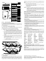
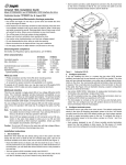
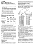
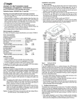
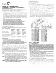
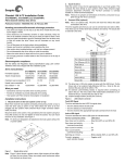
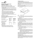
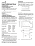
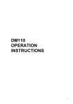
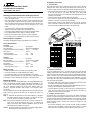
Installation instructions
1. Set the SCSI ID
Determine which SCSI IDs are already being used in the system and then
assign this disc drive a SCSI ID that isn’t already being used. Use the J6
connector located on the front of the drive to set the SCSI ID (see Figure 1).
Cheetah X15 Installation Guide
ST318451LW/LC and ST39251LC
SCSI interface disc drives
Publication Number: 83329485, Rev. B, September 2000
Handling precautions/Electrostatic discharge protection
• Disc drives are fragile. Do not drop or jar the drive and handle the drive
only by the edges or frame.
• Drive electronics are extremely sensitive to static electricity. Keep the
drive in its antistatic container until you are ready to install it. Wear a wrist
strap and cable connected to ground. Discharge static from all items near
or that will contact the drive. Never use an ohmmeter on any circuit
boards.
• Turn off the power to the host system during installation.
• Always use forced-air ventilation when operating the drive.
• Use caution when troubleshooting a unit that has voltages present.
• Do not disassemble the drive; doing so voids the warranty.
• Return the entire drive for depot service if any part is defective.
• Do not apply pressure or attach labels to circuit board or drive top.
Electromagnetic compliance
See Safety and Regulatory Agency Specifications, p/n 75789512.
• Most Cheetah X15 drives are factory set with the SCSI ID set at 0. If this
is the only SCSI drive in your system and there are no other SCSI
devices on the daisychain, you can leave this drive’s SCSI ID set to 0 and
proceed to the next step.
• The host system’s SCSI controller usually uses SCSI ID 7.
• If you have an LC model drive, the host normally sets the ID over the I/O
interface, so you don’t need to worry about this step.
• Some systems provide a cable designed to connect to the J5 jumper
block on the drive to remotely set the ID. You can connect this cable to J5
and use the host-provided remote switch to set the SCSI ID.
Drive
Front
Drive HDA
Rear
Jumper Plug
(enlarged to
show detail)
Pin 1
ST318451
Formatted capacity .................................... 18.35 Gbytes
Max. data blocks ....................................... 35,843,670 (0222EE56h)
Cylinders and heads (user accessible) ...... 10,377 / 10 heads
Disc rotation ............................................... 15k rpm
+5V
Typical operating current ......................... 0.8A
+12V
1.03A
ST39251
Formatted capacity .................................... 9.2 Gbytes
Max. data blocks ....................................... 17,921,835 (0111772Bh)
Cylinders and heads (user accessible) ...... 10,377 / 5 heads
Disc rotation ............................................... 15k rpm
Operating voltages
+5V
Ground
Pin 1
J5
Pin 1
J1
DC Power
J6
Drive characteristics
Operating voltages
68 Pin
SCSI I/O
Connector
+5V
Typical operating current ......................... 0.79A
+12V
Reserved
SCSI ID = 0
L R
E E
D S
4P
A3 A2 A1A0
(default)
• Phillips screwdriver and four 6-32 UNC drive mounting screws
• Forced-air ventilation to provide adequate drive cooling
• An unused drive power connector (not applicable to LC models)
To operate at LVD transfer rates, you may also need an LVD-capable SCSI
host adapter, LVD I/O cable and active negation external terminator
Multimode interface
This drive can operate in single-ended (SE) or low voltage differential (LVD)
mode. This multimode capability provides backwards compatibility so you
can use it with or without an LVD-capable host adapter. The primary benefits of LVD technology include faster transfer rates, reduced power consumption, increased allowable cable lengths, and improved device
connectivity.
You can configure the drive to switch between SE and LVD modes automatically or force it to operate in SE mode only. To configure this option, see
Figure 2.
Note. To operate at the Ultra2 rates in LVD mode, all devices on the same
bus (cable) must be running in LVD mode. If you add any SE device
to the bus, all devices on that bus operate in SE mode.
Note. Some LVD host adapters provide an LVD connector and an SE connector on the same host adapter to allow you to run SE and LVD
drives concurrently at their maximum capabilities. Check your SCSI
host adapter documentation. See Figure 3.
Caution. Do not mix LVD drives on the same bus with high voltage differential (HVD) devices–drive damage may occur.
SCSI ID = 0
(default)
PCBA
SCSI ID = 2
SCSI ID = 2
SCSI ID = 3
SCSI ID = 3
SCSI ID = 4
SCSI ID = 4
SCSI ID = 5
SCSI ID = 5
SCSI ID = 6
SCSI ID = 6
SCSI ID = 7
SCSI ID = 7
SCSI ID = 8
SCSI ID = 8
SCSI ID = 9
SCSI ID = 9
SCSI ID = 10
SCSI ID = 11
SCSI ID = 12
SCSI ID = 13
SCSI ID = 14
SCSI ID = 15
SCSI ID = 10
SCSI ID = 11
SCSI ID = 12
SCSI ID = 13
SCSI ID = 14
SCSI ID = 15
not used
0.93A
What you need
1P
SCSI ID = 1
SCSI ID = 1
Figure 1.
3P 2P
J1
A3 A2 A1A0
Setting the SCSI ID
2. Configure termination
If you are installing the drive in a system that has other SCSI devices
installed, terminate only the end devices on the SCSI bus (cable). This drive
does not have internal terminators or any other way of adding internal termination on the drive. You must provide external termination when termination
is required. This is normally done by adding an inline terminator on the end
of the cable. See Figure 3 for an illustration showing a system configuration
that uses a external terminator.
• Use active (ANSI SCSI-2 Alternative 2) single-ended terminators when
terminating a bus operating in single-ended mode.
• Use SPI-2-compliant active low voltage differential terminators when terminating a SCSI Ultra2 bus operating in LVD mode.
• The host adapter is normally on the end of the bus and internally terminated. You can configure your bus with another device on the end if you
remove termination from the host adapter.
3. Configure terminator power
Terminators have to get power from some source. The default configuration
results in the drive not supplying termination power to the bus. You should
normally leave this drive set at this default unless your host system requires
the drive to supply termination power to the bus. To configure this drive to
supply termination power to the bus, place a jumper on J2 pins 1 and 2 as
shown in Figure 2.
• Host systems designed to use LC drives normally provide termination
power from the host adapter or other source. For this reason, LC model
drives cannot be configured to provide termination power to the bus.
J2
Drive with
HDA up, PCB
down, viewed
from front
Pin 1
HDA
Protect against power failure or other power interruptions during the format.
Reserved Positions
Delay Motor Start option (valid
only if the Enable Motor Start
jumper is not connected)
J6
Reserved
inoperable. A low level format, with verify turned on, will typically take two
hours.
Pin 1
L R
E EA A A A
D S 3 2 1 0
(default)
Disable the Delay Motor Start option.
Motor start delay equal to the
SCSI ID multiplied by 12 seconds.
Reserved
11
Remote
LED
Motor Start option
12
CATH
Shipped with cover installed.
Do not remove.
Do not install jumpers
on these four positions.
Disable motor start (default). The
drive starts according to the Delay
Motor Start option.
(default)
Enable motor start. The drive waits for
the Start Unit command from the host
before starting the spindle motor.
J6 Jumper
Drive Front
J6
Write Protect option
Write protect = Off (enables writing).
(default)
Write protect = On (disables writing).
Pin 1
End
Parity Check option
(default)
Enable parity check of SCSI bus.
J2
Disable parity check.
Pin 1
Single-ended I/O
A jumper here forces single-ended
I/O operation.
DC Power
Connector
J1
J2 Jumper
SCSI I/O
Connector
No jumper allows host to select either
single-ended or LVD operation.
(default)
Option select jumpers.
5. Check the other available jumper settings
Select other options on J2 as illustrated in Figure 2. Do not change these
unless instructed to do so by the host system documentation.
6. Mount the drive in the host system and connect cables
Note. LC drives are designed to be attached to a carrier or tray and
inserted into the host system without I/O or power cables.
a. Mount LW model drives to the host system’s chassis using four 6-32
UNC screws. Two mounting holes are in each side of the drive and
there are four mounting holes in the bottom of the drive. Do not
over-tighten or force the screws. You can mount the drive in any orientation.
b. Connect the SCSI I/O cable into the drive’s SCSI connector. Take
care not to stretch or crimp this cable, and do not block the system’s
cooling air flow with the cable.
Note. For Ultra2 and faster operation, special twisted pair LVD
cables are required.
Connect the DC power cable to the drive. See Figure 3.
Ultra160 or Ultra2 LVD bus segment
Pin 1
(check your
adapter for
Pin 1 location)
SCSI
LVD/SE
SCSI
SPI-2 compliant
active LVD
external terminator
on the end of
the cable
Twisted Pair
LVD Cable
• MicrosoftTM. Set the drive type in CMOS to “Zero,” “None,” or “No hard
drive installed.” Use FDISK.EXE and FORMAT.EXE. Systems using Windows 98 or later can create one single partition (drive letter) on the drive.
• MacintoshTM. Use a third-party drive utility (most revisions of Apple’s HD
Setup utility only work with drives having special Apple firmware).
Troubleshooting
4. Connect the drive activity LED (optional)
Connect the Drive Activity LED cable to J6 pins 11 and 12 (see Figure 2), or
connect a drive ID and Drive Activity LED cable to J5, depending on host
system requirements.
c.
Caution. Formatting a drive erases all user data. Be sure that you understand this principle before formatting any hard disc drive. It is not
necessary to format a drive that previously has been used to
store data, unless your intention is to erase all user data. Seagate
is not responsible for lost user data.
Cheetah X15 disc drives are designed to operate with a variety of operating
systems. Please refer to your system or SCSI controller manual for information about formatting and setting up the drive. Some quick desktop system
notes are provided below.
(default)
Terminator Power
Term. Power to SCSI Bus
Host adapter or other device provides
term. power to external terminator.
Figure 2.
a. Turn on DC power to the host system.
b. Boot the system from a system floppy, CD, or from a previously
installed hard disc drive if there is one.
c. Format the drive.
SE
Host
Adapter
PCB
• Drive does not spin up. Check cables and all jumper settings. Make
sure cable pin 1 (edge stripe) matches PCB pin 1.
• Drive spins, but no LED on/off activity. Check SCSI ID setting. Set the
ID so that each device on the SCSI chain has its own unique ID. See also
the next item below. Host I/O controller is usually ID7.
• Computer does not seem to recognize the drive. Verify that the drive
is enabled by the SCSI host adapter setup utility.
• FDISK does not detect the drive. Run the FDISK program located on
your Windows startup diskette. Type fdisk/status to verify that your hard
drive is present.
Seagate support services
For online information about Seagate products, visit www.seagate.com or email your disc questions to [email protected]
If you need help installing your drive, consult your dealer first. If you need
additional help, call a Seagate technical support specialist. Before calling,
note your system configuration and drive model number (ST318451LW or
ST318451LC).
Africa
Australia
Austria
Belgium
Denmark
France
Germany
Hong Kong
Ireland
Italy
Middle East
Netherlands
Norway
+31-20-316-7222
+61-2-9725-3366
0 800-20 12 90
0 800-74 876
80 88 12 66
0 800-90 90 52
0 800-182 6831
800-90-0474
1 800-55 21 22
800-790695
+31-20-316-7222
0 800-732-4283
800-113 91
Poland
Spain
Sweden
Switzerland
Singapore
Taiwan
Turkey
United Kingdom
USA/Canada/
Latin America
Other European
countries
00 800-311 12 38
900-98 31 24
0 207 90 073
0 800-83 84 11
+65-488-7584
+886-2-2514-2237
00 800-31 92 91 40
0 800-783 5177
1-800 SEAGATE or
+1-405-936-1234
+31-20-316-7222
Warranty. Contact your place of purchase or our web site (above).
Return Merchandise Authorization (RMA). Before returning the drive, verify that it
is defective. Seagate Worldwide customer service centers are the only facilities authorized to service Seagate drives. Contact nearest center for return procedures and trade
regulations.
Shipping the drive
Caution. Back up the data before shipping. Seagate assumes no responsibility for
data lost during shipping or service. Shipping drive in an unapproved container voids
the warranty. Pack the drive with original box and packing materials. Use no other
materials. This prevents electrical and physical damage in transit.
Ultra SCSI SE bus segment
Figure 3.
Cable connections and external termination
7. Format the drive
The drive has been low level formatted at the factory. You do not need to
perform another low level format on this drive unless you decide to perform
certain diagnostics through the host adapter. If you do decide to perform a
low level format, do not abort the format as this is likely to make the drive
© 2000 Seagate Technology, LLC All rights reserved
Publication number: 83329485, Rev. B, September 2000, Printed in U.S.A.
Seagate, Seagate Technology, the Seagate Logo, and Cheetah are either registered
trademarks or trademarks of Seagate Technology, LLC. All other trademarks are the
property of their respective owners.