1
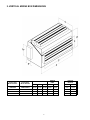
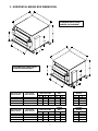
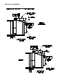
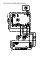
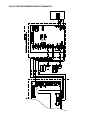
MODELS DSH/DSV
R-410A AIR SIDE ECONOMIZER KIT
Form 145.11-IOM1 (412)
AIR SIDE ECONOMIZER
FOR DSH AND DSV R-410A
AIR COOLED AIR CONDITIONING UNITS
INSTALLATION INSTRUCTIONS
B Style
IMPORTANT!
READ BEFORE PROCEEDING!
GENERAL SAFETY GUIDLINES
This equipment is a relatively complicated apparatus.
During installation, operation, maintenance or service,
individuals may be exposed to certain components or
conditions including, but not limited to: refrigerants, oils,
materials under pressure, rotating components, and
both high and low voltage. Each of these items has the
potential, if misused or handled improperly, to cause
bodily injury or death. It is the obligation and responsibilty of operating/service personnel to identify and
recognize these inherent hazards, protect themselves,
and proceed safely in completing their tasks. Failure to
comply with any of these requirements could result in
serious damage to the equipment and the property in
which it is situated, as well as sever personal injury or
death to themselves and people at the site.
This document is intended for use by owner-authorized
operating/service personnel. It is expected that this
individual possesses independent training that will enable them to perform their assigned tasks properly and
safely. It is essential that, prior to performing any task
on this equipment, this individual shall have read and
understood this document and any referenced materials.
This individual shall also be familiar with and comply with
all applicable governmental standards and regulations
pertaining to the task in question.
SAFETY SYMBOLS
The following symbols are used in this document to alert the reader to areas of potential hazard.
DANGER indicates an imminently hazardous situation which, if not avoided,
will result in death or serious injury.
WARNING indicates a potentially hazardous situation which, if not avoided,
could result in death or serious injury.
CAUTION identifies a hazard which
could lead to damage to the machine,
damage to other equipment and/or
environmental pollution. Usually and
instruction will be given, together with a
brief explanation.
NOTE is used to highlight additional information which may be helpful to you.
All wiring must be in accordance with published specifications and must be performed ONLY by
qualified service personnel. Johnson Controls will not be responsible for damages/problems
resulting from improper connections to the controls or application of improper control signals.
Failure to follow this will void the manufacturer’s warranty and cause serious damage to property or
injury to persons.
CHANGEABILITY OF THIS DOCUMENT
In complying with Johnson Controls policy for
continuous product improvement, the information
contained in this document is subject to change
without notice. While Johnson Controls makes no
commitment to up-date or provide current
information automatically to the manual owner, that
information, if applicable, can be obtained by
contacting the nearest Johnson Controls service
office.
It is the responsibility of operating/service personnel
as to the applicability of these documents to the
equipment in question. If there is any question in the
mind of operating/service personnel as to the
applicability of these documents, then, prior to
working on the equipment, they should verify with
the owner whether the equipment has been modified
and if current literature is available.
TABLE OF CONTENTS
4 …… Installation
5 ……Mixing Box Dimensions &
Component Layout
6 …….Interconnection Harness
7 ……Damper & Actuator Set-up
10 …. Wiring Schematics
12 …. Sequence of Operation
PRIOR TO INSTALLING OR SERVICING THE UNIT, LOCK ALL ELECTRICAL POWER SUPPLY
SWITCHES IN THE OFF POSTION. FAILURE TO DISCONNECT POWER SUPPLY MAY RESULT IN
ELECTRICAL SHOCK OR EVEN DEATH.
3
1. INSTALLATION
Horizontal/Vertical Economizers
1. Attach mixing box to unit evaporator return,
using the metal securing strip provided.
Fasteners may also be used around the
perimeter of the mixing box, at the location of
the filter frame, for additional security. This is
intended to connect the units, and not to support
the full weight of the economizer mixing box –
ADDITIONAL FIELD SUPPORT IS REQUIRED.
This may be from the ceiling, or from beneath
the unit.
2. Determine which inlet will be outside air, and
which will be return air.
If the normal
open/closed position of the dampers needs to be
reversed, remove the actuator, reset the damper
positions so that the outside air damper is
closed and the return air damper is fully open.
Adjust the linkage rod to these normal positions,
and secure. Reattach the actuator so that it is
rotating in the appropriate direction.
3. The module is connected to the unit wiring via a
2-part wiring harness. Minimal field rewiring of
the unit is required in order to accommodate the
Air-Side Economizer option. Refer to Section 6
for detailed instructions. Connect the wiring
harness to the microprocessor board as
indicated in Section 4 – Wiring Harness
Installation.
4. With the power to the module, the actuator
springs will wind and lock.
The enthalpy
changeover setting may be altered, and the
outside air damper minimum position adjusted.
See the attached Honeywell information for
details.
Prior to installing or servicing the
unit, lock all electrical power supply
switches in the OFF position. Failure
to disconnect power supply may
result in electrical shock or even
death.
Additional field support of the mixing
box is required. Failure to provide
adequate support for the unit may
result in injury or even death.
Exercise care when working around
the sharp metal edges of door panels
or flanges. These edges are sharp
and can cause injury.
2. VERTICAL MIXING BOX DIMENSIONS
Vertical Unit
Model Number
Economizer
Model Number
DSV060B
VASE-060B-1
DSV096B/120B
VASE-120B-1
DSV144B/180B
DSV240B
VASE-180B-1
VASE-240B-1
MIXING BOX DIM'N
DAMPER
DIM'N
CONTROL
MODULE
A
B
C
D
E
F
G
49.00
66.50
78.00
86.00
27.75
36.25
35.75
41.25
24.00
26.50
28.50
34.00
40.00
58.00
70.00
78.00
14.00
19.50
19.50
25.00
8.00
15.00
8.00
15.00
8.00
8.00
15.00
15.00
4
3. HORIZONTAL MIXING BOX DIMENSIONS
STANDARD SIDE & FRONT
DAMPER ARRANGEMENT
OPTIONAL BOTTOM & FRONT
DAMPER ARRANGEMENT
Horizontal Unit
Model Number
Economizer
Model Number
DSH024B/036B
HASE-036B-SF
DSH048B/060B
HASE-060B-SF
DSH096B
HASE-100B-SF
Horizontal Unit
Model Number
Economizer
Model Number
DSH024B/036B
HASE-036B-BF
DSH048B/060B
HASE-060B-BF
DSH096B
HASE-100B-BF
MIXING BOX DIM'N
DAMPER
DIM'N
CONTROL
MODULE
A
B
C
D
E
F
G
26.06
29.68
33.63
23.32
23.44
25.25
23.44
30.44
33.63
17.00
24.00
28.00
14.00
14.00
19.50
8.00
15.00
8.00
15.00
8.00
15.00
MIXING BOX DIM'N
DAMPER
DIM'N
CONTROL
MODULE
A
B
C
D
E
F
G
26.06
29.68
33.63
23.32
23.44
25.25
23.44
30.44
33.63
17.00
24.00
28.00
14.00
14.00
19.50
8.00
15.00
8.00
15.00
8.00
15.00
5
of the harness will enter through the knockout
hole in this area. Ensure the harness is secured
on the outside of the unit using the cable clips
provided.
4. WIRING HARNESS INSTALLATION AIRSIDE ECONOMIZER TO UNIT
CONNECTION
Each Air-Side Economizer is shipped complete with
a two-part wiring harness. The terminated end of the
wiring harness that is shipped in a package with the
economizer must be field wired into microprocessor
board. The second part of the harness assembly is
pre-wired into the Economizer module panel. The
two parts of the harness are connected together by
integrated polarized molex plugs.
Installing Harness (Horizontal Units):
1) Working from the evaporator blower access
door, feed the loose pre-terminated ends of the
harness along the base of the unit towards the
right end and back out, using the low voltage
electrical conduit, to the condenser section and
into the condenser electrical panel. For split unit
applications the harness will need to be
extended in the field using 18 gauge wire.
Ensure the cable is protected from damage and
the wiring meets all local code requirements.
All Models
6 Pin Molex Plug
Pin #
Color
Connection ID
1
Yellow/Red
Y-OUT
2
Yellow/Red
ECON
3
Gray/Red
G-OUT
4
Pink
OCCUPIED
5
White
COMMON
2) Inside the condenser electrical box, connect the
harness terminations to the microprocessor
board economizer harness terminations (Y-Out,
G-Out, ECON, and OCCUPIED), as shown in
the electrical schematic. Note that the Occupied
terminal is not being used in the standard factory
setup and has been provided if required in the
field.
Installing Harness (Vertical Units):
3) Connect the WHITE COMMON wire from the
harness onto the Common tab on the
microprocessor board, using the provided tab
adapter, as shown in the electrical schematic.
1) Working from the side access door, feed the
loose pre-terminated ends of the harness in
through the back of the low voltage section of
the electrical box, through the bushed hole.
4) Inside the blower section of the evaporator unit
secure the harness along base towards the left
corner post using the supplied cable clips.
Ensure that the harness is routed clear of
moving parts and sharp edges, and that there
are no loose wires that can be pulled into the
blower inlet. Coil excess wire length, and secure
with cable clips (see photo).
2) Connect the harness terminations to the
microprocessor board economizer harness
terminations (Y-Out, G-Out, ECON, and
OCCUPIED), as shown in the electrical
schematic.
3) Connect the WHITE COMMON wire from the
harness onto the Common tab on the
microprocessor board, using the provided tab
adapter, as shown in the electrical schematic.
5) The plug end of the harness should terminate
inside the bottom left corner post. The
economizer half of the harness will enter through
the knockout hole in this area. Use a punch out
tool or screwdriver. Feed the plug end harness
through and connect to the other half of the
economizer harness. Ensure the harness is
secured on the outside of the unit using the
cable
clips
provided.
4) Inside the condenser section secure the harness
to the side of the blower housing using the
supplied cable clips. Ensure that the harness is
routed clear of moving parts and sharp edges,
and that there are no loose wires that can be
pulled into the blower inlet. Coil excess wire
length, and secure with cable clips (see photo).
5) The plug end of the harness should terminate
inside the rear corner post. The economizer half
6
ECONOMIZER – DAMPER & ACTUATOR SETUP (VERTICAL SETUP)
Installed Harness
VERTICAL ECONOMIZER
HORIZONTAL ECONOMIZER
SINGLE STAGE ECONOMIZER WIRING SCHEMATICS
DUAL STAGE ECONOMIZER WIRING SCHEMATICS
6. SEQUENCE OF OPERATION
Modulating Economizer with Typical Electro Mechanical Thermostat
The Honeywell W7215 module, ML series actuators,
JCI damper sections, and factory wiring harness
comprise an integrated economizer.
These
economizers are used to provide ventilation and free
cooling for the JCI Series of vertical, and horizontal,
air handlers.
The Honeywell W7215 can accept inputs from
additional optional sensors, including a return-air
enthalpy sensor (for differential enthalpy control) or
a CO2 sensor (for Indoor Air quality strategies).
The economizer module also provides a provision
for remote damper position control. Min. and max.
damper position settings can be remotely controlled
using the P and P1, and Q and Q1 terminals on the
economizer module. For more information regarding
these features, consult the Honeywell W7215
manual included with the Economizer kit.
Powering the Thermostat (24vac) Power to the electromechanical thermostat is
provided from R terminal of the JCI unit’s low voltage
terminal strip. Electromechanical thermostats do not
require a 24vac common connection.
Powering the W7215 (24vac) The W7215 is powered from the JCI unit’s
microprocessor board at the G-Out pin whenever the
fan of the evaporator section is operating. To ensure
that the W7215 is continuously powered, the fan
switch on the thermostat sub-base should be left on
at all times.
High Enthalpy Sequence:
When the outside air enthalpy exceeds the enthalpy
set-point, the economizer W7215 module terminals
1 and 2 are closed and economizer will be forced
into the minimum damper position setting. The JCI
unit’s microprocessor board will control cooling
requirements.
Low Enthalpy Sequence:
When the outside air enthalpy is below the enthalpy
set-point, W7215 economizer terminals 1 and 2 are
opened and free cooling is activated. The JCI unit’s
microprocessor board turns off compressor
operation.
Damper Modulation:
On all JCI units' the C7046 temperature sensor
should be located in the discharge air duct. Locating
the sensor in the discharge air provides effective
'low-limit' sensing and control.
The outside-air
damper remains at minimum position if the
0
0
discharge air temperature is below 50 F or 10 C. If
0
0
the discharge air temperature is between 50 to 56
0
0
F (10 to 13.3 C) the outside air damper will
modulate between minimum position and fully open.
0
0
Above 56 F (13.3 C) the outside air damper will
remain in the fully open position.
Occupied:
The OCCUPIED harness terminal is not connected
to the economizer controller. It has been provided if
site conditions require field connection of an
Occupied function. Consult the Honeywell W7215
Economizer Controller Manual for more information.
Subject to change without notice. Printed in U.S.A.
Copyright© 2012 by Unitary Products Group. All rights reserved.
Engineered Systems
Products
Group
Form 145.11-IOM1 (412)
P.O. Box 1592
York, PA
17405
York
PA
17405