1
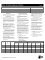
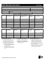
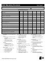
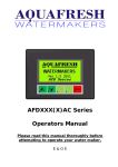
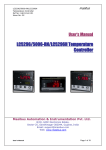
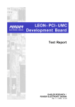
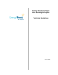
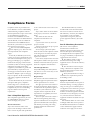
Compliance Forms HVAC
Compliance Forms
Compliance forms are provided in the
User’s Manual to assist in understanding
and documenting compliance with the
HVAC requirements. Copies of the forms
are provided both in printed and
electronic form. Modifiable electronic
forms are included on the CD distributed
with the Manual, as well as available for
download from the ASHRAE website.
The HVAC system forms are organized in
three parts and on five pages.
▪ Part I is used with the Simplified
Approach Option (§ 6.3). This is the only
form required with this compliance
option.
▪ Part II, the Mandatory Provisions,
consists of two pages and should be used
with either the Prescriptive Path (§ 6.5) or
Energy Cost Budget (§ 11) compliance
methods. The first page contains header
information, tables for entering equipment
efficiencies for heating and cooling
equipment, and checklists of general and
special mandatory requirements. The
second page contains the HVAC System
Worksheet. Multiple copies of each page
may be required to list all central heating
and cooling equipment and all HVAC
systems.
▪ Part III should only be used for the
Prescriptive Path (§ 6.5) compliance
method. Page one is a checklist of the
prescriptive requirements and needs to be
completed only once for each building.
Page two addresses the fan power
requirements.
Part I: Simplified Approach
This compliance approach may be used
for small buildings with two or fewer
floors and single, zone systems.
Header Information
Project Name. Enter the name of the
project. This should agree with the name
that is used on the plans and specifications
or the common name used to refer to the
project.
Project Address. Enter the street address
of the project, for instance “142 Minna
Street."
Date: Enter the date when the
compliance documentation was
completed.
City: The name of the city where the
project is located.
Zip/Postal Code: Enter the zip or postal
code of the project site.
HVAC Designer of Record/Telephone:
Enter the name and the telephone number
of the designer of record for the project.
This will generally be the mechanical
engineer or contractor.
Contact Person/Telephone: Enter the name
and telephone number of the person who
should be contacted if there are questions
about the compliance documentation.
Checklist Qualification
Only small buildings less than 25,000 ft²
and with two or fewer stories may use the
Simplified Approach.
Requirements
This section of the form summarizes the
Simplified Approach requirements. Each
form is separated into two sections.
The upper part of the form contains a
list of the requirements. Check each box
to indicate that the requirement applies to
the HVAC system and that the system
complies with the requirement. If the
requirement is not applicable, then leave
the box unchecked.
The lower part of the form contains a
table for entering heating and cooling
capacities and efficiencies for comparison
against the Standard. The rated capacity
and efficiency for heating and cooling
should be taken from manufacturers
specifications.
User’s Manual for ANSI/ASHRAE/IESNA Standard 90.1-2004
The Minimum Efficiency columns
should include values taken from Tables
6.8.1 and 6.3.2. The last column “Econ.
Min. Efficiency” need only be completed
if an exception to the economizer
requirement is being taken, based on
greater equipment efficiency (See Table
6.3.2).
Part II: Mandatory Provisions
This section of the compliance
documentation summarizes the
Mandatory Provisions. These apply with
either the Prescriptive Path or Energy
Cost Budget Method of compliance. The
two pages of mandatory requirements are
organized into three sections:
▪ The efficiency tables on Page 1
document that heating and cooling
equipment meets or exceeds the efficiency
requirements.
▪ The check boxes in the lower part
of Page 1 demonstrate compliance with
the general and special provisions of the
Mandatory Provisions.
▪ The Systems Worksheet on Page 2
summarizes the requirements specific to
air-handling systems.
Equipment Efficiency Tables
Enter the requested data for each piece of
mechanical heating or cooling equipment
using one entry per row. Identical pieces
of equipment can be entered as a group on
a single line. For each row, enter data
from the mechanical equipment schedules
and Tables 6.8.1 (A through G). For each
row, enter data from the mechanical
equipment schedules and Tables 6.2.1 (H
through J).
Non-standard chillers are water-cooled
centrifugal chillers that cannot operate at
the ARI Standard 550/590 test conditions
of 44°F chilled water supply and 85°F
condenser water supply. Use the lower
6-79
HVAC Compliance Forms
worksheet for these chillers (if any exist in
the building).
General and Specific
Mandatory Provisions
The lower part of the Page 1 form
contains the general and special system
requirements. Check the box to indicate
that the requirement applies to the HVAC
system and that the system complies with
the requirement. If the requirement is not
applicable, then leave the box unchecked.
Systems Worksheet
Page 2 contains the mandatory
requirements for HVAC systems. Data for
each system or group of identical systems
should be entered in the columns. The
first five rows are data that can be
obtained from the mechanical equipment
schedules (system tag, supply airflow,
supply external static pressure, supply fan
motor rated horsepower, and outdoor air
airflow). The remaining 11 rows contain
the mandatory requirements. For each
requirement enter the appropriate code
from the notes below the table. For
example, for the Automatic Shutdown
requirement (§ 6.4.3.2.1), if a complying
time switch with manual override is
provided on the system the user should
enter the code “C1.”
Part III: Prescriptive
Requirements
This section of the compliance
documentation summarizes the
prescriptive requirements. The first page
has a checklist of the prescriptive
requirements.
Prescriptive Economizer
Requirements
Check all of the boxes that apply for
HVAC systems in this project. Note: if
systems are exempt from the economizer
6-80
requirement, mark the basis for the
exception in the space provided. If a
requirement is not applicable, then leave
the box unchecked.
Prescriptive Air-System Requirements
The next section contains the air-system
requirements. Check all of the boxes that
apply to HVAC systems in this project. If
a requirement is not applicable, then leave
the box unchecked.
Prescriptive Water-System
Requirements
The next section contains the watersystem requirements. Check all of the
boxes that apply to HVAC systems in this
project. If a requirement is not applicable,
then leave the box unchecked.
Prescriptive Special System
Requirements
Check all of the boxes that apply to
HVAC systems in this project. If a
requirement is not applicable, then leave
the box unchecked. If none of the
requirements are applicable, the form may
be omitted.
horsepower for all the rows in the boxes,
the table, and in the worksheet where
indicated by the arrows. The first value in
the worksheet is entered from Table
6.5.3.1 in the Standard. This value depends
on the total supply airflow and the type of
system (constant volume or variable
volume). The total system horsepower
allowance is calculated from the following
equation:
HP Allowance
(6-H)
Table 6.5.3.1Value Total Supply Airflow
1,000
There are corrections for the
horsepower allowance for low
temperature supply, high pressure filters,
pressure drop for evaporative cooling or
heat recovery equipment, and relief fans
that operate during peak cooling. To use
these corrections, the user must attach
calculations using the equations from
§ 6.5.3.1 of the Standard.
Fan Power Limitations
Fill out the worksheet on Page 2 for each
fan system with greater than 5 nameplaterated horsepower. Groups of identical
systems may be combined into a single
worksheet. The table has 10 columns. The
first three are for the tag, supply airflow
and nameplate-rated horsepower for each
of the supply fans in the system. There are
two columns each for the tag and
nameplate rated horsepower for the return
and exhaust fans and a pair for each of the
series-style fan-powered boxes (if
appropriate). Sum the motor horsepower
for each row and enter the total in the
“total system motor (hp)” column on the
far right. Enter the sum of the supply fan
airflow and total system motor
User’s Manual for ANSI/ASHRAE/IESNA Standard 90.1-2004
HVAC Simplified Approach Option
Part I
Project Name:
Project Address:
Date:
City:
Zip:
HVAC System Designer of Record:
Telephone:
Contact Person:
Telephone:
Qualification
The building is 2 stories or less in height and
2
has a gross floor area is less than 25,000 ft .
Requirements
(a) All systems serve a single HVAC zone.
(b) Cooling (if any) is provided by a unitary
packaged or split-system air conditioner that
is either air-cooled or evaporatively cooled
and meets the efficiency requirements shown
in Table 6.8.1. List equipment in the table
below.
(c) The system has an air economizer as
required by Table 6.5.1, with controls as
required in Tables 6.5.1.1.3A and 6.5.1.1.3B.
The economizer has either barometric or
powered relief sized to prevent
overpressurization of the building. Outdoor air
dampers for the economizer use are provided
with blade and jamb seals.
Exception: The cooling efficiency meets
or exceeds the efficiency requirement in
Table 6.3.2. Document in table below.
(d) Heating (if any) shall be provided by a
unitary packaged or split-system heat pump,
a fuel-fired furnace, an electric resistance
heater or a baseboard system connected to a
boiler. All heating equipment meets the
efficiency requirements of the Standard. List
equipment in table below.
Exception: An energy recovery
ventilation system is provided in
accordance with the requirements in
§ 6.5.6.
(f) The system shall be controlled by a
manual changeover or dual setpoint
thermostat.
(g) Heat pumps equipped with auxiliary
internal electric resistance heaters (if any)
have controls to prevent supplemental heater
operation when the heating load can be met
by the heat pump alone.
(h) The system controls do not permit reheat
or any other form of simultaneous heating
and cooling for humidity control.
(i) Systems are provided with a time switch
that (1) can start and stop the system under
different schedules for seven different daytypes per week; (2) is capable of retaining
programming and time setting during a loss
of power for a period of at least 10 h; (3)
includes an accessible manual override that
allows temporary operation of the system for
up to 2 h; (4) is capable of temperature
setback down to 55 F during off hours; and
(5) is capable of temperature setup to 90 F
during off hours.
Exception: System serves hotel/motel
guest rooms.
Exception: Piping is located within
manufactured HVAC units.
(k) Ductwork and plenums are insulated in
accordance with Tables 6.8.2A and 6.8.2B
and sealed in accordance with Tables
6.4.4.2A and 6.4.4.2B.
(l) Construction documents require air
systems to be balanced in accordance with
industry-accepted procedures to within 10%
of design airflow rates.
(m) Where separate heating and cooling
equipment serve the same temperature zone,
thermostats are interlocked to prevent
simultaneous heating and cooling.
(n) Exhausts are equipped with gravity or
motorized dampers that will automatically
shut when systems are not in use.
Exception: System operates
continuously.
Exception: Design capacity is less than
300 cfm.
Exception: System operates
continuously.
(o) Systems have optimum start controls.
Exception: System has both a cooling
or heating capacity less than 15,000
Btu/h and a supply fan motor power
greater than 3/4 hp.
(e) The outdoor air quantity is less than or
equal to 3,000 cfm and less than or 70% of
the supply air quantity at minimum outdoor air
design conditions.
(j) Piping is insulated in accordance with
Table 6.8.3. Insulation exposed to weather is
suitable for outdoor service. Cellular foam
insulation is protected from water and solar
radiation.
Exception: Supply air capacity is less
than 10,000 cfm.
Equipment Efficiency
System
Tag(s)
Mfg. &
Model
No.
Equipment
Type
Heating
Rated
Capacity
ANSI/ASHRAE/IESNA Standard 90.1-2004
Rated
Efficiency
Cooling
Minimum
Efficiency
Rated
Capacity
Rated
Efficiency
Minimum
Efficiency
Econ.
Min.
Efficiency
HVAC Mandatory Provisions
Part II, Page 1
Project Name:
Project Address:
Date:
HVAC System Designer of Record:
Telephone:
Contact Person:
Telephone:
City:
Climate Zone:
Zip:
1% Summer DB Temp:
1% Summer WB Temp:
99.6% Winter Temp:
Mandatory Equipment Efficiency Worksheet (§ 6.4.1.1)
System Tag
Equipment Type (Tables
6.8.1A through G)
Size Category (Tables
6.8.1A through G)
Sub-Category or Rating
Condition (Tables 6.8.1A
through G)
Units of Efficiency
(Tables 6.8.1A
through G)
Minimum Efficiency (Tables
6.8.1A through G)
Rated
Required
Mandatory Non-Standard Centrifugal Chiller Worksheet (§ 6.4.1.1)
System Tag
Leaving CHW
Temperature (°F)
Entering CW
Temperature (°F)
Condenser Flow Rate
(gpm/ton)
Size Category
(Tables 6.8.1H
through J)
Minimum Efficiency (Tables
6.8.1H through J)
Rated
General Mandatory Requirements
Load calculations are provided for selection
of all equipment and systems (§ 6.4.2).
Stair vents, elevator shaft vents, gravity
hoods, gravity vents and gravity ventilations
are provided with motorized dampers.
Exception: Gravity dampers are used
since the building is less than 3 stories
or in climate zones 1–3.
Exception: No vents are required as
these systems ventilate unconditioned
zones.
ANSI/ASHRAE/IESNA Standard 90.1-2004
Piping insulation meets or exceeds the
requirements of the Standard (§ 6.4.4.1.3).
Construction documents require record
drawings (§ 6.7.2.1), manuals (§ 6.7.2.2),
system balancing (§ 6.7.2.3) and system
commissioning (§ 6.7.2.4).
Required
Special Mandatory Requirements
Freeze protection or snow/ice melting
systems (if any) have controls to prevent
operation in warm weather (§ 6.4.3.7).
Independent perimeter heating systems (if
any) comply with the control requirements of
§ 6.4.3.1.1 and § 6.4.3.2.
Independent heating and cooling thermostatic
controls (if any) are interlocked to prevent
crossover of set points (§ 6.4.3.2).
HVAC Mandatory Provisions
Part II, Page 2
Project Name:
Contact Person:
Telephone:
Systems Worksheet (§ 6.4)
System Tag
Supply CFM
Supply ESP (in. w.c.)
Fan System HP
OA CFM (i.e. Outdoor Air CFM)
Automatic Shutdown (§ 6.4.3.2.1)
Deadband (§ 6.4.3.1.2)
Setback Controls (§ 6.4.3.2.2)
Setup Controls (§ 6.4.3.2.2)
Optimum Start (§ 6.4.3.1.3)
Zone Isolation (§ 6.4.3.1.4)
Shutoff Dampers (§ 6.4.3.3.3)
Heat Pump Aux Heat (§ 6.4.3.4)
Humidifier Preheat (§ 6.4.3.5)
Humidification/Dehumidification Deadband (§ 6.4.3.6)
Ventilation Control (§ 6.4.3.8)
Duct/Plenum Insulation (§ 6.4.4.2.1)
Duct Sealing Levels (§ 6.4.4.2.1) Supply/Return
Duct Leakage Test (§ 6.4.4.2.2)
In the table above, enter the appropriate codes
from this list:
Shutdown
C1 Complying nonresidential time switch
with override
C2 Complying residential time switch with
override
N1 N/A continuous operation
N2 N/A 15 kbtu/h or 3/4 hp
N3 N/A hotel/motel guestroom
Dead Band
C1 Dual setpoint control
C2 Manual change over control
N1 N/A special occupancy (requires
approval)
N2 N/A heating or cooling only
Setback Controls
C1 Setback provided (down to 55F)
N1 N/A continuous operation
N2 N/A 15 kbtu/h or 3/4 hp
N3 N/A 99.6% Win DB>40F
N4 N/A radiant heating
N5 N/A no heating
ANSI/ASHRAE/IESNA Standard 90.1-2004
Setup Controls
C1 Setup provided (up to 90F)
N1 N/A continuous operation
N2 N/A 15 kbtu/h or 3/4 hp
N3 N/A 1% Sum DB<=100F
N4 N/A no cooling
Heat Pump Aux Heat
C1 Complying controls provided
N1 N/A system is not a heat pump
N2 N/A auxiliary is not electric or is not
provided
N3 N/A heat pump covered by NAECA
Optimum Start
C1 Optimum start provided
N1 N/A continuous operation
N2 N/A 15 kbtu/h or 3/4 hp
N3 N/A supply<=10,000 cfm
Humidifier Preheat
C1 Complying controls provided
N1 N/A no humidifier
Shutoff Dampers
C1 Motorized shutoff dampers on OA and
Exh
C2 Gravity shutoff dampers on OA and Exh
N1 N/A continuous operation
N2 N/A 15 kbtu/h or 3/4 hp
N3 N/A OA/EA <=300 cfm
Zone Isolation
C1 Isolation zones provided
N1 N/A continuous operation
N2 N/A 15 kbtu/h or 3/4 hp
N3 N/A all zones on same schedule
N4 N/A OA/EA <=5,000 cfm
Humidification/Dehumidification Dead Band
C1 Complying controls provided
N1 N/A no humidification and/or
dehumidification
Duct/Plenum Insulation
C1 Complying insulation provided
N1 N/A all ducts located in conditioned
space
Duct Sealing
Enter highest seal level (A, B or C) for
supply and return
Duct Leakage Test
Y Ducts will be tested for leakage
N Ducts will not be tested for leakage
HVAC Prescriptive Requirements
Part III, Page 1
Project Name:
Contact Person:
Telephone:
Prescriptive Checklist
Prescriptive Economizers (§ 6.5.1)
Systems employ airside economizers
(§ 6.5.1.1).
Economizer provides up to 100% design
airflow in outdoor air (§ 6.5.1.1.1).
Economizer is integrated with the mechanical
cooling system (§ 6.5.1.1.2 and § 6.5.1.3).
Specify economizer exemptions:_____
________________________________________
________________________________________
________________________________________
____________________
Prescriptive Air-System Requirements
Zone minimums were set to meet the
requirements of Standard 62.
Economizer dampers meet or exceed
leakage requirements (§ 6.5.1.1.4).
Zone minimums were set to 0.4 cfm/ft of
zone conditioned floor area.
2
Other (requires special documentation and
approval).
Humidity controls (if any) comply with the
requirements of § 6.5.2.3.
Systems that employ hydronic cooling and
have humidification (if any) use a waterside
economizer that complies with § 6.5.1.
Variable air volume fan controls comply with
the requirements of § 6.5.3.2.
Systems employ waterside economizers.
Economizer can provide 100% of the load at
either the outdoor conditions of 50°F db/45°F
wb or 45°F db/40°F wb where required for
dehumidification purposes (§ 6.5.1.2.1).
Precooling coils and heat exchangers have
either a 15 ft of WC pressure drop or are
bypassed when economizer is not in use (§
6.5.1.2.2).
Economizer is integrated with the mechanical
cooling system (§ 6.5.1.3).
Systems are exempt from the economizer
requirements.
ANSI/ASHRAE/IESNA Standard 90.1-2004
All heat rejection equipment with motors 7.5
hp employ controls that comply with § 6.5.5.
Exhaust Air Energy Recovery: all fan systems
that have both a design supply capacity of
5,000 cfm and a minimum outdoor air supply
of 70% of the design supply air employ an
energy recovery system that complies with
§ 6.5.6.1.
Heat recovery for service water heating is
provided for facilities that operate
continuously, have a total water-cooled heat
rejection capacity exceeding 6,000,000 btu/h,
and have a design service water heating load
exceeding 1,000,000 btu/h. The heat
recovery system (if any) complies with
§ 6.5.6.2.
Kitchen hoods with exhaust flows > 5000 cfm
comply with the requirements of § 6.5.7.1.
Fume hoods with a total exhaust system flow
> 15,000 cfm comply with the requirements of
§ 6.5.7.2.
Radiant heaters complying with § 6.5.8.1 are
used to heat unenclosed spaces (if any).
The cooling equipment with hot-gas bypass
controls (if any) meets the unloading
requirements of § 6.5.9.
Prescriptive Water-System Requirements
Three-pipe systems are not used (§
6.5.2.2.1).
Two-pipe changeover heating/cooling
systems (if any) comply with the
requirements of § 6.5.2.2.2.
Hydronic (ground- or water-loop) heat pump
systems that have equipment for both loop
Economizer complies with the heating system
impact requirements (§ 6.5.1.4).
System pumps greater than 10 hp employ
variable flow controls (§ 6.5.4.1), pump
isolation (§ 6.5.4.2) and temperature reset
(§ 6.5.4.3).
Zone minimums are less than 300 cfm.
System provides relief for up to 100% design
airflow in outdoor air (§ 6.5.1.1.5).
Prescriptive Special System Requirements
Simultaneous Heating and Cooling
(§ 6.5.2.3).
Economizer high limit shutoff complies with
§ 6.5.1.1.3.
Economizer complies with the heating system
impact requirements (§ 6.5.1.4).
heat addition and loop heat rejection (if any)
comply with the requirements of § 6.5.2.2.3.
HVAC Prescriptive Requirements
Part III, Page 2
Project Name:
Contact Person:
Telephone:
Complete one worksheet for each fan system > 5hp
Prescriptive Fan Power Limitations (§ 6.5.3.1)
Supply Fan
Tag
Supply CFM
Return Fan
Motor (hp)
Tag
Motor (hp)
Exhaust Fan
Tag
Motor (hp)
Total Supply CFM
Tag
Total System
Motor (hp)
Motor (hp)
Total System Motor HP
Table 6.5.3.1 Value
Total Supply CFM
X
Constant
HP Allowance
Credits and/or adjustments*
Series-Style Fan-Powered
Box
Adjusted HP Allowance*
________
hp/cfm
________
cfm
1,000
=
________
hp (=Value X CFM/1000)
___________
________
hp (see § 6.5.3.1)
___________
* Attach calculations and documentation if credits or temperature adjustments are used. Refer to § 6.5.3.1 for the formulas
Credits and adjustments are available for the following:
Clean filter pressure drops in excess of 1 in. w.c.;
Pressure drop due to heat recovery coils or devices or evaporative cooling equipment or devices;
Relief fans that operate during peak cooling due to high ventilation rates; and
Room to cooling air supply temperature differences that are greater than 20°F (e.g. low temperature supply).
ANSI/ASHRAE/IESNA Standard 90.1-2004