1
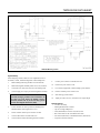
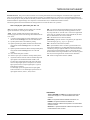
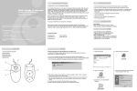
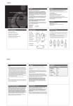
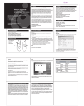
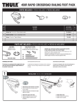
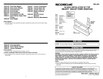
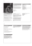
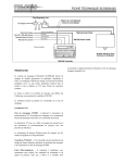
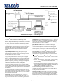
TMP3200/090 DATASHEET
TMP3200/090 Marking System – General Arrangement
System Overview
The Telesis® TMP3200/090 PINSTAMP® marking system
permanently prints messages into a variety of materials such as steel,
aluminum, and plastic. A hardened pin is pneumatically accelerated to
indent dot matrix characters into the item being marked. The shape,
size, density, and location of characters are determined by the user
through the system software. The marking head moves the pin
cartridge through X- and Y-axis motions to reach the correct position
for each dot of the characters to be marked. The system software
automatically controls pin extension and retraction to mark the
message.
Marking Pins for the TMP3200 include the 25S-, 25L-, 25XL- and
the 150SA-series. Refer to the marking head installation drawing
for pin stroke (pin extension) dimensions. Refer to the marking
depth tables for pin cone angles and depths.
TMP3200 Marking Head includes the mechanical motion
components to position the marking pin at precise X/Y positions
and the pneumatic components to drive the marking pin out from,
and return the pin into, the pin cartridge.
System Computer runs the Merlin®II marking system software
and generates commands to control the marker. The system
computer must be equipped with an add-on USB v2.0 board and
must satisfy one of the following configurations:
• Windows® 2000 or Windows® XP or Windows® Vista™ operating
system with Belkin® model F5U219 PCI USB 2.0 board
(full-size PCs);
• Windows® 2000 or Windows® XP or Windows® Vista™ operating
system with Belkin® model F5U219LP PCI USB 2.0 board
(low-profile PCs);
• Windows® 2000 or Windows® XP or Windows® Vista™ operating
system with Belkin® model F5U222 or IOGEAR® model GPU202
PCMCIA USB 2.0 board (laptop or notebook PCs).
The TMP3200 marking head is an X/Y-traversing mechanism.
Using two stepper motor drives, it accurately and rapidly positions
the pin at coordinate-defined locations in marking window within
.03175 mm (.00125"). The marker accommodates the rigorous
dynamics of impacting, rebounding, and rapid positioning of the
marking pin through a system of rigid rails and ball bearing
saddles, timing belts, and direct-drive, toothed pulleys.
The floating pin design permits high quality, consistent marks on
irregular, slightly curved surfaces. It also accommodates applications
where marking surfaces cannot be positioned at a consistent distance
from the marker.
The internal mechanism is protected from debris by an integral
shield. Stainless steel panels slide against one another, constrained
by the cartridge and the high-impact ABS cover, to prevent debris
from entering the marking head.
Marker Cable, pre-wired to the marking head, connects the
marker to the controller. The highly flexible cable is 4m (13 ft.
long. Optional extension cables are available for greater distances.
Doc. No. 37061 Rev. J
Filter/Regulator Unit includes two regulators with pressure
gauges to control the drive air and return air. The first regulator
contains a filter to help remove contaminants from the supply air.
Two air lines connect the regulated air to the marking head. Drive air
fires the impact pin; return air pushes it back into the cartridge. The
standard air lines are 4m (13 ft.) long made of 6 mm tubing.
To take full advantage of the Merlin II RS232 or TCP/IP
capabilities, the system computer must have an available RS232 or
TCP/IP port for the host interface.
TMC090 Controller connects to the system computer through a
USB interface. Commands are passed from the PC to the controller,
then on to the marker and its optional equipment. The TMC090
interface panel provides ports for connecting additional I/O devices
for remote operation.
© 2003 – 2007 Telesis Technologies, Inc. – All Rights Reserved
1 of 6
TMP3200/090 DATASHEET
TMP3200 Mounting Details
System Setup
When designing a fixture, allow for 3-axis adjustment to aid in
horizontal, vertical, and lateral alignment of the marking head.
1.
Mount marking head using four M6-1.00 x 20 mm bolts.
9.
Connect power cables to controller and to PC.
2.
Mount filter/regulator assembly within 4 m (13 ft.) of marker.
10.
Position PC power switch to ON.
3.
Connect drive air and return air lines to the marking head.
11.
For customer-supplied PC, install marking system software.
4.
Connect supply air to input port on filter/regulator assembly.
12.
Position controller power switch to ON.
13.
Start marking system software.
14.
Adjust pin stroke, drive air, and return air for impact depth.
Note: The controller is not a sealed unit. Protect it from
potentially damaging conditions and contaminants. Do
not block case vents. Ensure the marking system is
electrically isolated from any devices that may generate
extreme electromagnetic interference (EMI).
5.
Locate controller as close as practical to marking head.
Standard marker cable length is 4m (13 ft.).
6.
Ensure controller and PC power switches are OFF.
7.
Connect USB cable to controller and to PC.
8.
Connect marker cable from marking head to controller.
Doc. No. 37061 Rev. J
System Options
• Tool Post Assembly
• Marking Head Extension Cables
• Clip-on Cartridge Adapter Kit
• Theta (Rotational) Axis and/or Z (Vertical) Axis
• Bar Code Scanner or Bar Code Wand with Cable
• Foot Switch (Start Print) or Pushbutton Station (Start/Abort)
• Logo/Font Generator Software
2 of 6
TMP3200/090 DATASHEET
TMP3200 Marking Head
Specifications. The TMP3200 marking head specifications are
subject to change without prior notice.
DIMENSIONS
seeTMP3200 Mounting Drawing
WEIGHT
6.8 kg (15 lb.), marking head and cable
OPERATING TEMP.
0° to 50°C (32° to 122°F), non-condensing
AIR SUPPLY
Clean and dry, 4.0 to 6.9 bars (60 to 100 psi)
AIR CONSUMPTION
0.04 SCFM (idle) 0.8 SCFM (marking)
MARKING AREA
150 x 100 mm (6.0 x 4.0")
PIN TYPES
25S-, 25L, 25XL, or 150SA-series
PIN MATERIAL
Powdered metal or stainless steel with diamond tip
or carbide (25S, 25L, 25XL series)
Powdered metal or tool steel with carbide tip
(150SA-series)
Marking Characteristics. The TMP3200 can produce characters
as small as .76 mm (.030"), printed at any angle within the marking
window. Printing resolutions range from 4 to 79 dots per cm (10 to
200 dots per inch) for an engraved look. The depth of mark can be
adjusted over a significant range by adjusting the pin stroke and, to
a lesser extent, by adjusting the drive air pressure.
Pin Life. Pin life depends largely on the type of material being
marked, how hard or abrasive it is, and the required marking depth.
On typical metals with a hardness of Rockwell Rb47, marking at a
depth of .005" (.127 mm), powdered steel pins average about 3
million impressions before needing sharpened; carbide pins average
approximately 9 million impressions. If carbide pins are used,
marking times will increase by approximately 25% due to the
increased weight of the pins.
Marking Speeds. The system will mark up to four characters per
second when marking 3 mm (.118 in.) high, 5 x 7 dot matrix
characters using a 25S powdered steel marking pin with the
standard 25S cartridge, with a pin stroke of 3 mm (.118 in.) and the
drive air pressure set to 5.5 bars (80 psig). The marking speed can
be adjusted to allow more precisely formed characters. Doing so,
under these same conditions, will result in reduced marking speeds.
Note that marking speeds vary widely depending on character size,
drive air pressure, dot density, pin stroke, pin type and pin
cartridge. Increased character size, increased dot density, increased
pin stroke, and/or decrease drive air pressure all result in decreased
marking speeds. The use of a heavier marking pin, such as the 25S
carbide pin or the 150SA carbide-tipped pin, or the use on nonstandard marking pin cartridges will also result in decreased
marking speeds. Specific times and speeds can be verified by a
Telesis representative.
Doc. No. 37061 Rev. J
Marking Noise. Although every attempt is made to reduce noise,
the material being marked significantly influences the noise level.
For example, marking a solid lead block produces less noise than
marking a thin-walled steel pipe.
Marking Depth. The following tables provide sample marking
depths. Drive air was set at 5.5 bars (80 psi); return air was set at
1.5 bars (20 psi); pin stroke was set to the maximum allowable
distance for each pin type to achieve the maximum depth of mark.
Max. Marking Depths – Type 25S Powdered-Metal Pin
MATERIAL
(HARDNESS)
Aluminum
(Rb2)
Brass
(Rb22)
Cast Iron
(Rb47)
Cold Rolled Steel
(Rb53)
30°
CONE
45°
CONE
60°
CONE
.178 mm
.007 in.
.152 mm
.006 in.
.127 mm
.005 in.
.102 mm
.004 in.
.229 mm
.009 in.
.178 mm
.007 in
.152 mm
.006 in.
.127 mm
.005 in.
.279 mm
.011 in.
.203 mm
.008 in.
.178 mm
.007 in
.152 mm
.006 in.
Max. Marking Depths – Type 25S Carbide Pin
MATERIAL
(HARDNESS)
Aluminum
(Rb2)
Brass
(Rb22)
Cast Iron
(Rb47)
Cold Rolled Steel
(Rb53)
30°
CONE
45°
CONE
60°
CONE
.178 mm
.007 in
.152 mm
.006 in.
.127 mm
.005 in.
.102 mm
.004 in.
.229 mm
.009 in.
.203 mm
.008 in.
.178 mm
.007 in
.152 mm
.006 in.
.305 mm
.012 in.
.254 mm
.010 in.
.203 mm
.008 in.
.178 mm
.007 in
Max. Marking Depths – Type 150SA Carbide-Tipped Pin
MATERIAL
(HARDNESS)
Aluminum
(Rb2)
Brass
(Rb22)
Cast Iron
(Rb47)
Cold Rolled Steel
(Rb53)
30°
CONE
45°
CONE
.356 mm
.014 in.
.229 mm
.009 in.
.203 mm
.008 in
.203 mm
.008 in.
.457 mm
.018 in.
.330 mm
.013 in.
.279 mm
.011 in.
.254 mm
.010 in.
Merlin II Visual Design Software
The marking system software runs on the system PC and connects to
the controller via the USB port. It provides a 32-bit user interface to
design pattern files and to operate the marker. The software is an
easy-to-use, graphical-design application that provides tools for
creating, saving, loading, and editing user-defined patterns. Each
pattern contains one or more fields; each field defines a single object.
Printable objects may be created to define text strings, arc-text
strings, geometric shapes , graphics, and machine-readable data
matrix symbols. Non-printable objects may be defined to specific
commands to the marker (e.g., Pause, Go to, Input, or Output).
Printable text fields may include alphanumeric characters, symbols,
and special message flags. Message flags automatically insert data
into the text string, such as serial numbers, times, dates and userdefined codes.
3 of 6
TMP3200/090 DATASHEET
TMC090 Mounting Drawing
TMC090 Controller
Specifications. The TMC090 controller specifications are subject
to change without prior notice.
refer to TMC090 Mounting Drawing
NEMA 1 (I.P. 30)
WEIGHT
2.15 kg ( 4.75 lb.)
OPERATING TEMP. 0° to 50°C (32° to 122° F), non-condensing
REQUIRED POWER 95-130 VAC, 2 amps, 50-60 Hz single phase
200-250 VAC, 1 amp, 50-60 Hz single phase
I/O VOLTAGE
12 to 24 VDC (customer-supplied)
Environmental Considerations. The following environmental
considerations must be taken into account when installing the
TMC090 controller.
DIMENSIONS
RATING
Contaminants. The vented and fan-cooled TMC090 is rated
NEMA 1 (IP30). Accordingly, in environments where solid
and/or liquid contaminants are present, the possibility exists that
these contaminants can be drawn into the TMC090 controller
and possibly result in failure of a number of electronic
components. For that reason, in these types of environments, the
controller must be located in a sealed industrial enclosure.
EMI Susceptibility. Although the system has been found to be
in compliance with pertinent susceptibility standards, care
should be taken when installing near welders and other extreme
generators of electromagnetic interference (EMI). Particular care
should be taken to ensure welder currents are not injected
through the marking head chassis. The marking head chassis is
connected to the electrical service earth ground through the
marking head cable. The marking head should be electrically
isolated from all surfaces which could become part of a welder
current path.
Doc. No. 37061 Rev. J
4 of 6
TMP3200/090 DATASHEET
Interface Panel. The interface panel provides various ports for
connecting the controller to the marking system equipment. The
Marker port, USB port, and Aux Axis port are used to connect the
marking head, system PC, and optional auxiliary axes, respectively.
I/O control signals may be connected to the I/O port and the TTL
Input port. (See I/O Control Signals.) RS-232 and TCP/IP
communications may be connected to the PC and routed to the
marker through the USB port. (See Host Communications.)
TCP/IP Interface. The Ethernet (TCP/IP) interface is most often
used with host computers communicating over a local area network
(LAN). With this type of interface, you may use either Extended
Protocol or Programmable Protocol.
The Port parameter identifies the host computer socket that is
assigned to the marking system. If more than one marking system
is installed in a network configuration, each system must use a
separate and unique port number. The Address parameter identifies
the IP (Internet Protocol) address of the host computer. The
marking system software supports both fixed addressing and
dynamic addressing.
Host Communications. The marking system software allows you
to configure communication parameters to transmit and receive
data to and from a host computer or a remote I/O device. The host
communicates with the marking system software via the host
interface on the system PC. The software passes information to
and from the marking equipment via the controller USB interface.
To provide maximum integration flexibility, the system software
supports Ethernet (TCP/IP) interfaces and serial (RS-232)
interfaces. It also provides two protocol choices: Programmable
Protocol and Extended Protocol.
Programmable Protocol. Use this protocol where very simple
one-way communications are required (such as with bar code
scanners). Programmable Protocol provides no error checking or
acknowledgment of the transmitted data. Note that XON/XOFF
Protocol applies even when Programmable Protocol is selected.
Starting Character specifies where the software begins to count
character positions. This number must be entered in ASCII
decimal format such as 2 for STX.
Terminating Character identifies the end of transmitted string
(usually ASCII carriage return character, decimal 13).
RS-232 Interface. The serial (RS-232) communications interface
is most often used with remote devices such as host computers,
terminals, or bar code scanners. The RS-232 interface supports both
Extended Protocol and Programmable Protocol.
Character Position counted from the starting character ignoring
all characters preceding it.
The following describes the serial data character format on all
transmissions to and from the system PC.
Ignore Character identifies the character to ignore when sent
from the host (usually ASCII line feed character, decimal 10).
•
Asynchronous
•
300, 600, 1200, 2400, 4800, 9600, 19200, 38400,
57600, or 115200 Baud
•
1, 1.5, or 2 Stop Bits
•
5, 6, 7, or 8 Data Bits
•
None, Even or Odd Parity
Character Length accepts variable length messages (if set to 0)
or messages of a pre-specified, fixed number of characters.
Message Type allows message-type recognition which defines
how the marking system will use data it receives from the host.
49 (Type 1) overwrites first text field with data extracted from
the host
80 (Type P) loads a specific pattern identified by data extracted
from host
81 (Type Q) updates text in first query buffer with data extracted
from host
I/O Control Signals. The TMC090 is configured for DC I/O only.
The TTL Input port may be used to connect a remote push button
control for sending Start Print and Abort commands to the marker.
86 (Type V) updates first variable text field with data extracted
The I/O port may be used to connect a PLC or other DC I/O source.
The I/O port allows remote control of printing, aborting, and
monitoring of the Ready and Done output signals. Additionally, the
I/O port allows for remote pattern selection. The marking system
can monitor four separate input signals and, based on the on/off
state of those signals, will select and open a specific pattern stored
on the PC.
0
Cable connectors and connector pins are supplied with the controller
for constructing appropriate interface cables.
START PRINT
Input signal: begin print cycle
SEL_0, 1, 2, 3
Input signals: pattern selection
ABORT
Input signal: abort print cycle
INPUT COMM
For all inputs (+ or – supply)
READY
Output signal: ready for message or start print
DONE
Output signal: print cycle complete
OUTPUT COMM
For all outputs (+ or – supply)
Doc. No. 37061 Rev. J
from host
(Type Zero) indicates that host will provide message type,
field number (if applicable), and data; delegates message
type selection to the host on message-by-message basis. The
host message must use the format Tnn<string> where:
T
= 1, P, Q, or V to indicate the message type.
nn
= two-digit number to indicate field number or
query text buffer where data will be placed. Note
that a number is not used with Message Type P.
<string> = field data (Message Types 1, Q, or V) or
pattern name (Message Type P) , as applicable.
5 of 6
TMP3200/090 DATASHEET
Extended Protocol. This protocol selection includes error checking and transmission acknowledgment. It should be used in applications
where serial communication is a vital part of the marking operation. All communications are carried out in a parent/child relationship with
the host being the parent. Only the host has the ability to initiate communications. If the host does not receive a response within three seconds, it
should re-transmit its original message. If no response is received after three tries, it should declare the link to be down.
The following describes the Extended Protocol message format as sent from the host to the system PC.
SOH TYPE [##] STX [DATA TEXT] ETX BCC CR
SOH ASCII Start of Header character (001H). The controller
ignores all characters received prior to the SOH.
TYPE A single, printable ASCII character that defines the
meaning (type) and content of the message downloaded from the
host, where:
1 overwrites specified field of currently loaded pattern, using
the data format nn<string> where nn is the field number.
P specifies pattern name to be loaded for printing
Q updates specified query buffer with data received from host,
using the data format nn<string> where nn is the buffer
number.
V updates specified variable text field of currently loaded pattern,
using the data format nn<string> where nn is the field
number.
O resets marker and places it online
G initiates a print cycle to mark the currently loaded pattern
I requests the marker return the status of standard output and
input signals in the hexadecimal format: O2 O1 ; I2 I1
The first digit of the hexadecimal code reports the signal
states of output signals Spare-3 and Spare-2. The second
digit reports the states of output signals Spare-1, Spare-0,
Pause, Ready, and Done.
The third digit reports the signals states of input signals
Select-4 and Select-3. The fourth digit reports the state of
input signals Select-2, Select-1, Abort, and Go.
[##] Two optional ASCII decimal digits that specify the Station
ID number for use in multi-drop network applications. The ID
may range from 00-31. Note that “00” is reserved for applications
where only one controller is used. In such applications, this field
may be eliminated and “00” will be assumed.
STX ASCII Start of Text Character (002H).
[DATA TEXT] Optional character string that may be required for
certain message types (e.g., Type 1, P, Q, and V).
ETX ASCII end of text character (003H).
BCC Optional Block Check Code that is generated and sent to
improve link reliability by providing fault detection. The BCC is
calculated by taking an eight bit addition of the TYPE and DATA
TEXT characters and transmitting them as a three digit ASCII
decimal number in the range from 000 to 255. If the sum is greater
than 255, the most significant bit overflows and is discarded.
CR ASCII Carriage Return Character (00DH).
TRADEMARKS
Telesis, PINSTAMP, and Merlin are registered trademarks of
Telesis Technologies, Inc. in the United States and/or other
countries.
Belkin is a registered trademark of Belkin International, Inc.
IOGEAR is a registered trademark of IOGEAR, Inc.
Vista is a trademark of Microsoft Corporation in the United States
and other countries.
Windows is a registered trademark of Microsoft Corporation in the
United States and other countries.
Doc. No. 37061 Rev. J
6 of 6