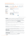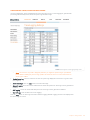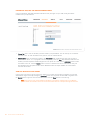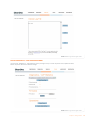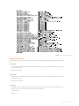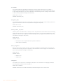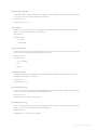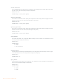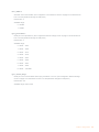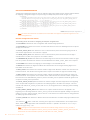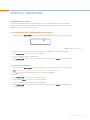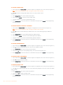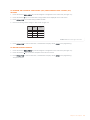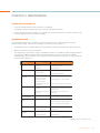
1
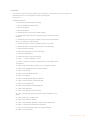
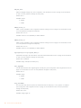
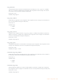
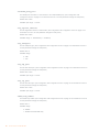
MAX™ IP Conferencing Phone
ADMINISTRATOR’S GUIDE
TABLE OF CONTENTS
TELEPHONE 1.800.283.5936
1.801.974.3760
FAX
EMAIL
1.801.977.0087
[email protected]
MAX IP ADMINISTRATOR’S GUIDE
CLEARONE PART NO. 800-158-302. JANUARY 2006 (REV.1.0)
© 2006 ClearOne Communications, iinc. All rights reserved. No
part of this document m ay be reproduced in any form or by any
means without written permission from ClearOne Communications.
Printed in the United States of America. ClearOne reserves specific
privileges. Inforfrmation in this document is subject to change without notice
TABLE OF CONTENTS CONTINUED
CHAPTER 1: INTRODUCTION
CHAPTER 4: MAINTENANCE
Product Overview . . . . . . . . . . . . . . . . . . . . . . . . . . . . . . . 1
Caring for Your MAX IP . . . . . . . . . . . . . . . . . . . . . . . . . 35
Service and Support . . . . . . . . . . . . . . . . . . . . . . . . . . . . 1
Troubleshooting . . . . . . . . . . . . . . . . . . . . . . . . . . . . . . . 35
Unpacking . . . . . . . . . . . . . . . . . . . . . . . . . . . . . . . . . . . . 3
CHAPTER 5: APPENDIX
CHAPTER 2: GETTING STARTED
Error Codes . . . . . . . . . . . . . . . . . . . . . . . . . . . . . . . . . . 37
Connecting Your Conferencing Phone . . . . . . . . . . . . . . 5
Specifications. . . . . . . . . . . . . . . . . . . . . . . . . . . . . . . . . 38
Connecting Additional MAX IP Phones . . . . . . . . . . . . . . 5
Compliance . . . . . . . . . . . . . . . . . . . . . . . . . . . . . . . . . . 39
Provisioning Your MAX IP Phone . . . . . . . . . . . . . . . . . . . 6
FCC Part 15/ICES-003 Compliance . . . . . . . . . . . . . . 39
Configuring the IP Address . . . . . . . . . . . . . . . . . . . . . . . 6
European Compliance . . . . . . . . . . . . . . . . . . . . . . . . 39
Configuring the DHCP Server . . . . . . . . . . . . . . . . . . . . . 6
Warranty . . . . . . . . . . . . . . . . . . . . . . . . . . . . . . . . . . . . . 39
Manually Assigning an IP Address . . . . . . . . . . . . . . . . . 7
Manually Provisioning Your MAX IP Phone . . . . . . . . . . . 7
Web Portal Screens . . . . . . . . . . . . . . . . . . . . . . . . . . . . . 8
Device Information Screen . . . . . . . . . . . . . . . . . . . . . . 8
Configuration: General Settings Screen. . . . . . . . . . . . 9
Configuration: User Preferences Screen . . . . . . . . . . 10
Configuration: Dial Plan Screen . . . . . . . . . . . . . . . . . 11
Configuration: Network Settings Screen . . . . . . . . . . 13
Configuration: SIP Configuration Screen . . . . . . . . . . 14
Configuration: Audio Settings Screen . . . . . . . . . . . . 16
Configuration: Trace/Logging Settings Screen . . . . . 17
Phonebook: Add, Edit, & Delete Number Screen . . . 18
View Log: Device Log File Screen . . . . . . . . . . . . . . . 18
Tools Diagnostics: VOIP Statistics Screen . . . . . . . . . 19
Automatically Provisioning Your MAX IP Phone . . . . . . 20
Firmware Files. . . . . . . . . . . . . . . . . . . . . . . . . . . . . . . 20
Phone Settings and Phone-specific Files . . . . . . . . . 20
Dial Plan Configuration File . . . . . . . . . . . . . . . . . . . . 30
CHAPTER 3: USER OPTIONS
Programming Options . . . . . . . . . . . . . . . . . . . . . . . . . . 31
To Change DHCP . . . . . . . . . . . . . . . . . . . . . . . . . . . . 31
To Change Host IP Address . . . . . . . . . . . . . . . . . . . . 31
To Change Subnet Mask . . . . . . . . . . . . . . . . . . . . . . 31
To Program Default Gateway IP Address. . . . . . . . . . 32
To Change Ringer Melody . . . . . . . . . . . . . . . . . . . . . 32
To Program Help Line Number. . . . . . . . . . . . . . . . . . 32
To Enable/Disable VLAN. . . . . . . . . . . . . . . . . . . . . . . 32
To Program AGC and ALC Settings . . . . . . . . . . . . . . 33
To Restore Factory Defaults . . . . . . . . . . . . . . . . . . . . 33
PRODUCT OVERVIEW
Thank you for purchasing the ClearOne Max™ IP expandable conferencing phone. MAX IP
provides premium, full-duplex audio to small conference rooms as a single unit and to larger
rooms as an expanded system. Up to four MAX IP units can be linked, expanding not only
microphone coverage but loudspeaker coverage and control access as well. This creates
even distribution of sound for a more natural communications experience.
Setting up the MAX IP conferencing phone requires only three connections: power, network, and the base unit
to the conferencing phone. And, the familiar keypad design ensures that you will be comfortable using the
phone, reducing the need for training, and support.
•
•
MAX IP is ideal for conference rooms and provides complete microphone and loudspeaker
coverage and easy access to controls.
EXPANDABLE.
SUPERIOR AUDIO.
The clear, full sound of the MAX IP facilitates more natural interaction among
participants.
•
ONE-TOUCH CONFERENCING.
•
EASY TO USE.
Single-button access to 3-way calling.
The intuitive, user-friendly controls are simple to operate.
SERVICE AND SUPPORT
If you need additional information on how to set up or operate your MAX IP conferencing phone, please
contact us. We welcome and encourage your comments so we can continue to improve our products and
better meet your needs.
PRODUCT RETURNS
All product returns require a return authorization (RA) number. Please contact ClearOne Technical Support
before attempting to return your product. Make sure you return all the items that shipped with your product.
Chapter 1: Introduction
1
IMPORTANT SAFETY INFORMATION
Read the safety instructions before first use of this product. This conferencing phone is not designed for
making emergency telephone calls when the power fails. Make alternative arrangements for access to
emergency services.
•
Read and understand all instructions and follow all warnings marked on the product.
•
Unplug this product from the wall outlet before cleaning. Do not use liquid cleaners or aerosol cleaners.
Use a damp cloth for cleaning.
•
Do not use this product near water, for example, near a bathtub, washbowl, kitchen sink, or laundry tub, in
a wet basement, or near a swimming pool.
•
Do not place this product on an unstable cart, stand, or table. The product may fall, causing serious
damage to the product.
•
Slots and openings in the cabinet and the back or bottom are provided for ventilation, to protect it from
overheating, these openings must not be blocked or covered. Never push objects of any kind through
cabinet slots as they may touch dangerous voltage points or short out parts that could result in a risk of
fire or electric shock.
•
This product should never be placed near or over a radiator or heat register. This product should not be
placed in a built-in installation unless proper ventilation is provided.
•
This product should be operated only from the type of power source indicated on the marking label. If you
are not sure of the type of power supply in your location, consult your dealer or local power company.
•
Do not overload wall outlets and extension cords as this can result in fire risk or electric shock.
•
Never spill liquid of any kind on the product.
•
To reduce the risk of electric shock, do not disassemble this product. Opening or removing covers may
expose you to dangerous voltages or other risks. Incorrect reassembly can cause electric shock during
subsequent use.
•
Unplug this product from the wall outlet and refer servicing to qualified service personnel under the
following conditions:
a. When the power supply cord or plug is damaged or frayed.
b. If liquid has been spilled into the product.
c. If the product does not operate normally by following the operating instructions.
d. If the product has been dropped or damaged.
e. If the product exhibits a distinct change in performance.
•
Avoid using a telephone during an electrical storm. There may be a remote risk of electric shock from
lightning.
•
Do not use this product to report a gas leak in the vicinity of the leak.
•
Do not use this product near intensive care medical equipment or by persons with pacemakers.
•
This product can interfere with electrical equipment such as answering machines, TV sets, radios,
computers and microwave ovens if placed too close.
Save these instructions
2
Technical Services: 800.283.5936
UNPACKING
Carefully place the conferencing pod and base unit on a level surface. Ensure you have received all items
shown in figure 1.
Conferencing pod
25' Connection cable
Base unit
7' Ethernet cable
Documentation on CD
Compliance and
safety sheet
Power Cord
FIGURE 1.1 MAX IP parts
>
Note: ClearOne is not responsible for product damage incurred during shipment. You must make claims
directly with the carrier. Inspect your shipment carefully for obvious signs of damage. If the shipment
appears damaged, retain the original boxes and packing material for inspection by the carrier. Contact
your carrier immediately.
The items shown in figure 2 are included in the Max IP Expansion Kit.
Conferencing pod
12' Connection cable
FIGURE 1.2 MAX IP expansion kit
Chapter 1: Introduction
3
4
Technical Services: 800.283.5936
CHAPTER 2: GETTING STARTED
CONNECTING YOUR CONFERENCING PHONE
1. Connect the Connection cable from the Link Out jack on the base unit to the Link In jack on the
conferencing pod (see figure 2.1).
Ethernet
Jack
To Link In
25' Connection cable
To Link Out
Green
Ethernet
cable
FIGURE 2.1 Connecting the MAX IP
Warning: DO NOT plug a laptop or PC into the Link Out jack on the base unit or conferencing pod--severe
electrical damage can occur if this is done.
2. Connect the base unit to the Ethernet jack using the Ethernet cable.
3. Connect the power cord to the base unit and plug it directly into an electrical outlet.
CONNECTING ADDITIONAL MAX IP PHONES
1. Connect the 12' Connection cable to the Link Out jack on the first phone and to the Link In jack on the
second phone (see figure 2.2).
From Link Out
25' Connection cable
To Link In
12' Connection cable
To Link In
To Link Out on Base Unit
FIGURE 2.2 Connecting additional units
2. Continue linking up to three additional MAX IP phones in the same fashion. A total of four units may be
connected.
Chapter 2: Getting Started
5
PROVISIONING YOUR MAX IP PHONE
There are two methods available for configuring your MAX IP phone:
•
The first method is manually, through the phone's keypad and a web portal associated with the phone.
•
The second method provisions the phone automatically when it is plugged into the network. This method
uses a DHCP server to assign the phone minimal IP information so that it can access the network, including an IP address, gateway, subnet mask, and TFTP server address. A TFTP server is then used to automatically upload firmware (when new firmware is available) and provisioning information to the phone, so
that it is ready to make a call after it has completed the booting sequence.
By default, the MAX IP is configured for automatic provisioning and assumes the IT administrator has correctly
configured the DHCP and TFTP servers on the phone network. When more than a few phones are to be
provisioned, it is recommended that you use the automatic method, otherwise the manual method is the best.
CONFIGURING THE IP ADDRESS
Before any other provisioning can be done, you must first configure the host IP address and the subnet mask
of the MAX IP phone. These must be known in order to provision the phone through the web interface. These
settings are usually obtained automatically from the DHCP server, however, they can also be assigned manually if the host IP address is to be a static IP address.
CONFIGURING THE DHCP SERVER
When configuring a DHCP server for use with the MAX IP phone, the following parameters should be
assigned:
•
IP address
•
Subnet mask
•
Gateway IP address
•
TFTP server IP address
•
DNS server IP address
•
Secondary DNS server IP address
•
DNS domain
The IP address and subnet masks are defined by DHCP option 1.
The Gateway IP address is defined by DHCP option 3.
The TFTP server is defined first by DHCP option 66. If this is undefined, then the MAX IP examines the siaddr
parameter in the DHCP ACK packet. If this is not defined, then the hostname parameter in the DHCP ACK
packet is used.
The DNS server IP address is defined by DHCP option 6.
The secondary DNS server IP address is defined by DHCP option 6.
The DNS domain is defined by DHCP option 15.
6
Technical Services: 800.283.5936
MANUALLY ASSIGNING AN IP ADDRESS
If DHCP is disabled, or you wish to assign a static IP address, then perform the following steps:
1. Press and hold the REDIAL/PROG key until the program icon appears on the LCD screen (see figure 2.3).
FIGURE 2.3 MAX IP LCD Program icon
>
Note: If a key is not pressed within 30 seconds of entering program mode, the MAX IP phone will beep
and return to operation mode.
2. Press the 2 key. The default IP address is displayed on the LCD screen. If this address was obtained from
DHCP, then you can use it to access the web interface. If you cannot access the web interface using this
address, then you need to either configure DHCP as explained above so that the IP address can be
obtained automatically, or you must manually enter a static IP address. Continue with step 3 to manually
enter a static IP address for the MAX IP phone.
3. Press the 1 key. The current DHCP setting is displayed on the LCD screen. A “1” indicates that DHCP
mode is enabled; a “0” indicates that DHCP mode is disabled.
4. If “0” is the current setting, then continue with step 8, otherwise continue with step 5.
5. Press the REDIAL/PROG key. The current DHCP mode “1” flashes on the LCD screen.
6. Press the 0 key. The new DHCP mode “0” flashes on the LCD screen.
7. Press the REDIAL/PROG key. DHCP mode is disabled.
8. Press the 2 key. The current IP address (such as 0.0.0.0) is displayed on the LCD screen.
9. Press the REDIAL/PROG key. The current IP address flashes on the LCD screen.
10. Press the CLEAR key. The current IP address is deleted one character at a time.
11. Using the number keys, enter the static IP address. Use the * key to enter the decimal separators in the IP
address.
12. Press the REDIAL/PROG key. The new static IP address is activated in the MAX IP phone.
13. Press the 3 key and repeat steps 9-12 above to set the subnet mask, then continue with step 14.
14. Press the REDIAL/PROG key. The MAX IP phone reboots.
MANUALLY PROVISIONING YOUR MAX IP PHONE
The easiest way to manually provision your MAX IP phone is through the web interface. To access the web
interface for your MAX IP phone, perform the following steps:
1. Press and hold the REDIAL/PROG key until the program icon appears on the LCD screen (see figure 2.3).
2. Press the 2 key. The phone’s IP address is displayed on the LCD screen.
3. Make note of the IP address and press the CLEAR key. Program mode is exited.
4. Start Internet Explorer (only the Internet Explorer web browser, release 6.0 or later with Java 1.5 or later
installed, works with the MAX IP phone).
5. Enter the phone’s IP address into the Internet Explorer address field and press the ENTER key on your
computer’s keyboard. (You can also enter the DNS name or the phone’s name on the network in order to
get to the web interface login screen.)
Chapter 2: Getting Started
7
6. The web interface login screen appears (see figure 2.4).
FIGURE 2.4 Login screen
7. Enter the default username admin and the default password clearone and click OK.
8. The web portal appears, displaying the Device Information screen.
WEB PORTAL SCREENS
The following sections display each of the screens included in the MAX IP web portal and describe all of the
settings that can be modified through each of the screens.
DEVICE INFORMATION SCREEN
The Device Information screen (see figure 2.5) displays all of the system information for your MAX IP phone.
The information fields are self-explanatory, however, note that the last four digits of the MAC address are used
as an identifier in the system name. By default, the system name is in the format of MAX1AV- followed by the
last four digits of the MAC address. The MAC address is a unique address in hexadecial format that can also
be found on the label attached to the back of your MAX IP base unit. This screen (and all other screens) also
includes a link to the Registration page in order to register your MAX IP phone with ClearOne. Simply click on
the Registration link to go there.
8
Technical Services: 800.283.5936
FIGURE 2.5 Device Information screen
CONFIGURATION: GENERAL SETTINGS SCREEN
Use the Configuration: General Settings screen (see figure 2.6) to set up security, provisioning, the MAX IP
extension and help line phone numbers, and when a reboot of the phone is allowed.
FIGURE 2.6 Configuration: General Settings screen
•
Security: To change your username and/or password, enter the new username and/or password in the
appropriate fields and then click the Apply button.
Chapter 2: Getting Started
9
•
Provisioning: Click the Use local settings radio button if you wish to use the settings programmed into your
MAX IP phone, including IP address, audio settings, and VLAN settings. Use this option if TFTP via DHCP
is unavailable or if you wish to manually provision your phone.
Click the Use DHCP/TFTP radio button to set the TFTP IP address. The IP address of the TFTP server can be
provided by the DHCP server or you can enter it manually. If the TFTP address is provided by the DHCP
server, then click the TFTP Address from DHCP radio button; if the TFTP server is set manually, then click the
Use TFTP Server radio button and enter the IP address of the TFTP server.
Click the Apply button to activate the changes.
•
Phone Numbers:To change or set the phone numbers for the MAX IP phone and help line, enter the phone
number for the MAX IP phone into the Local phone number field and the phone number for the help line into
the Help line number field and then click the Apply button.
•
Reboot: Choose when you wish to allow a reboot of the MAX IP phone. Click the Allow reboot during a call
radio button to allow a reboot while a call is in progress or click the Wait until current call ends radio button to
allow a reboot only after a call is completed, then click the Apply button.
CONFIGURATION: USER PREFERENCES SCREEN
Use the Configuration: User Preferences (see figure 2.7) screen to enable/disable automatic level control
(ALC) and automatic gain control (AGC), to mute/unmute the incoming ringer, to select the incoming ringer
melody, to set the time zone, and to determine if you want the time automatically adjusted for Daylight Savings
or not.
FIGURE 2.7 Configuration: User Preferences screen
10
•
Enable automatic level control: Click this check box to enable ALC or uncheck it to disable ALC. ALC
(automatic level control) automatically adjusts microphone levels to ensure participants' voices are
transmitted at consistent levels regardless of whether people are speaking loudly or softly.
•
Enable automatic gain control: Click this check box to enable AGC or uncheck it to disable AGC. AGC
(automatic gain control) adjusts (softer and louder) input audio to a consistent level.
•
Mute incoming ringer: Click this check box to mute the incoming ringer (or uncheck it to allow the ringer to
ring normally).
•
Incoming ringer melody: Click the drop-down box to select from the five available melodies. Click the Play
button to listen the selected melody on the phone.
•
Time zone: Click the drop-down box to select from the available time zones. Choose the time zone nearest
to your location. The time zone is necessary for logging functions, such as errors, and so forth.
Technical Services: 800.283.5936
•
Auto adjust for Daylight Saving Changes: Click this check box to have the time automatically adjusted for
Daylight Savings or uncheck it if Daylight Savings time is not observed in your area.
Click the Apply button to activate any changes made to this screen.
CONFIGURATION: DIAL PLAN SCREEN
Use the Configuration: Dial Plan (see figure 2.8) screen to view your current dial plan and to choose how you
want the dial plan for your MAX IP phone loaded. You can choose to have it loaded from a file containing all of
the settings you desire or you can select the settings you wish for your MAX IP phone manually through this
screen.
FIGURE 2.8 Configuration: Dial Plan screen
•
Current dial plan: Click the View hyperlink to see the current dial plan file (see figure 2.9) associated with your
MAX IP phone.
FIGURE 2.9 Current dial plan file
Chapter 2: Getting Started
11
•
Select new dial plan location: Click the radio button for the method you wish to use to have your dial plan
loaded into your MAX IP phone. Click the File radio button if you want the dial plan loaded from a file
located on the local PC or click the Manual configuration radio button if you want to set up the dial plan
manually through this screen. Note that when the file method is chosen, the Upload button is active and the
Apply button is inactive; when the manual configuration method is chosen, the Apply button is active and
the Upload button is inactive.
•
Load From File: If you are setting up this phone to be part of a group of phones with similar settings, then it
is recommended that you use the file method (see page 29 for more information on the dial plan
configuration file). This method ensures that each phone in the group uses the same dial plan settings.
(Although the name of your dial plan file can be any name you wish, it is stored in the MAX IP phone in a file
named C1MAX1AVDIAL.txt.) Your dial plan file can be located in different directories in order to provide for
different settings for different phones, such as different dial plans for domestic calls versus international calls.
Click the Browse button to navigate to the directory where the dial plan is located and then click the Upload
button to load the dial plan file into your MAX IP phone.
•
Manual Configuration: If you do not have a dial plan file set up and stored on your local PC, or if you wish
to create a dial plan for only this MAX IP phone, then you should use the manual configuration fields on
this screen.
>
Note: The manual settings are structured for typical dialing plans in the United States.
• Manual send key: Click the drop-down box and select the key you want to press after entering a dialed
number. Values are #, *, or none. If none is selected, then there is no terminating digit and the specified
number of digits must be entered before the phone will dial.
• Total dial timer: This is total time allowed to complete digit entry before a re-order is generated. Values
are 1, 2, and 3 minutes.
• Interdigit timer: This is the maximum amount of time allowed between digits entered into the phone after
the first digit is pressed, before digits are sent automatically. Values are 15, 30, and 45 seconds.
• Extension dialing: Click the drop-down box to select the number of digits in the telephone extension of
your organization’s extension configuration. Values are 3, 4, and 7 digits. Click the Enable check box to
enable this feature or uncheck the box to disable it.
• Local dialing (Prefix): Click the drop-down box to select the prefix required for dialing offsite. Values are 8
and 9. Click the Enable check box to enable this feature or uncheck the box to disable it.
• Long distance dialing (Prefix): Click the drop-down box to select the prefix for dialing offsite long
distance. Values are 81 and 91. Click the Enable check box to enable this feature or uncheck the box to
disable it.
• Emergency dialing: Click the drop-down box to select the number required for emergency dialing. Values
are 811 and 911.
• Operator dialing: Click the drop-down box to select the number required to reach the operator. Values
are 0.
Click the Apply button to activate any changes made to the manual configuration.
12
Technical Services: 800.283.5936
CONFIGURATION: NETWORK SETTINGS SCREEN
Use the Configuration: Network Settings screen (see figure 2.10) to set up your MAX IP phone on the network.
You can set the hostname, domain name, static IP address, subnet mask, default gateway, primary DNS IP
address, secondary DNS IP address, SNTP server 1 IP address, SNTP server 2 IP address, VLAN priority, and
VLAN ID from this screen, along with enabling/disabling DHCP and VLAN.
FIGURE 2.10 Configuration: Network Settings screen
•
Hostname: This is the name of the host (or the MAX IP’s device name on the network) and is the same as
the system name found on the Device Information screen.
•
Enable DHCP: Click this check box to enable DHCP on the MAX IP phone. When enabled, the settings for
domain name, static IP address, subnet mask, default gateway, primary DNS IP address, and secondary
DNS IP address are all grayed out as they are obtained automatically from the DHCP server. Uncheck this
box to disable DHCP. Note that the above-mentioned settings are now editable as you must enter the
appropriate values manually.
•
SNTP Server 1 and 2 IP Addresses: The SNTP servers are time servers. Enter the IP address of the desired
server and click Apply to go out and get the current time from the corresponding time server. The time
returned is in Greenwich Mean Time, adjusted according to the setting of the time zone (see Configuration:
User Preferences Screen on page 10 for more information on the time zone setting).
Chapter 2: Getting Started
13
•
Enable VLAN, VLAN Priority, and VLAN ID: VLAN is used to segment a single physical network into several
virtual networks. It is used to differentiate between VoIP (voice over IP) data and other data. Once VLAN is
enabled by clicking the check box next to Enable VLAN, you can set the VLAN priority. VLAN priority is the
priority of the MAX IP phone on the VLAN. Click the drop-down box next to VLAN Priority and select the desired
priority. Values are 0 to 7. The VLAN ID is a unique identifier set by the system administrator which can be of
any value between 1 and 4094.
>
•
Note: After VLAN is enabled, you will not be able to access the MAX IP phone through the web portal
unless your PC has access to the VLAN you just configured. To regain access to the web portal, you
will have to disable LAN (see To Enable/Disable VLAN on page 32).
QoS (Quality of Service): QoS is implemented on the MAX IP using DSCP (differentiated service code point).
The DSCP is a selector for a router’s per-hop behaviors. Each group of DSCPs (or class) has the same
precedence value, from 0 to 7, with the default precedence value for MAX IP being 5. Select the preferred
precedence value from the drop-down menu; advanced users can also enter a custom DSCP value in the
text field.
Click the Apply button to activate any changes made to the Network Settings screen.
CONFIGURATION: SIP CONFIGURATION SCREEN
Use the Configuration: SIP Configuration screen (see figure 2.11) to configure the SIP (session initiation
protocol) settings for your MAX IP phone. SIP is a text-based protocol that is based on HTTP and MIME, which
makes it suitable and very flexible for integrated voice-data applications. SIP relies on the session description
protocol (SDP) for session description and the real-time transport protocol (RTP) for actual
transport.
FIGURE 2.11 Configuration: SIP Configuration Settings screen
14
Technical Services: 800.283.5936
•
Enable Authentication: Click this check box to enable authentication or uncheck it to disable
authentication. (Authentication is required if the proxy requires it.) Authentication verifies the username and
password as entered in the Authorization user and Authorization password fields. These fields are active only
when authentication is enabled and can thus be modified. When authentication is disabled, these fields
are inactive.
•
Enable SIP Proxy registration: Click this check box to enable SIP proxy registration or uncheck it to disable
it. SIP proxy registration is the connection to the SIP proxy server in a SIP-based IP telephony environment
that handles call control and serves as the central repository for address translation (name to IP address).
When SIP proxy registration is enabled, the Proxy server IP address/URL and Proxy port fields are active. Enter
the required IP address/URL of the SIP proxy server and the number of the SIP proxy port. When SIP proxy
registration is disabled, these fields are inactive.
•
Enable Outbound proxy: Click this check box to enable the outbound proxy server or uncheck it to disable
it. The outbound proxy is the IP address to use for outbound calls if the address is different from the
registration address. When enabled, the Outbound proxy server IP address/URL and Outbound proxy port fields are
active. Enter the required IP address/URL of the outbound proxy server and the number of the outbound
proxy port. When disabled, these fields are inactive.
•
SIP Transport: Click the radio button next to the type of SIP transport you wish to use and the number of
the listen port in the Listen port field for the specified transport. UDP (user datagram protocol) is a protocol
within the TCP/IP protocol suite that is used in place of TCP (transmission control protocol) when a reliable
delivery is not required. UDP requires less processing of packets and is connectionless, meaning it does
not require a handshake to start a session like TCP does. Therefore, it is faster and is often used with VoIP
because there is no time to retransmit erroneous or dropped packets. The default port is 5060.
•
Enable in Band DTMF Relay: Click the check box to enable in band DTMF (dual tone multi-frequency)
relay or uncheck the box to disable it. In band DTMF relay allows dialing information to be sent for
gateways that need to receive standard audio. DTMF relay provides a way to transport DTMF digits in an
RTP voice stream when the voice codec cannot accurately reproduce the digits, or the sender or receiver
DSP (digital signal processor) cannot perform digit sampling. Each DTMF digit is encoded as an
RTP-named event and sent as RTP packets over UDP. The packets are encoded with a payload type which
is negotiated during connection establishment. When enabled, the Payload field is active. Enter the
desired payload: values range from 96 to 127. When Enable in Band DTMF Relay is disabled, this field is
inactive.
•
Registration timeout: Enter the value (in seconds) your phone is to refresh its registration to the SIP proxy
server. The default value is 3600.
Click the Apply button to activate any changes made to the SIP Configuration screen.
Chapter 2: Getting Started
15
CONFIGURATION: AUDIO SETTINGS SCREEN
Use the Configuration: Audio Settings screen (see figure 2.12) to configure the voice activation detection
settings and to prioritize your preferred audio codecs.
FIGURE 2.12 Configuration: Audio Settings screen
•
Enable VAD: Click the check box to enable VAD (voice activity detection) or uncheck the box to disable it
(VAD is enabled by default). Voice activity detection is a software application that allows a data network
carrying voice traffic over the internet to detect the absence of audio and conserve bandwidth by
preventing the transmission of “silent packets” over the network. VAD can also be used to forward idle
noise characteristics to a remote IP telephone so that the listener will not think the line has gone dead
when the speaker is not actively speaking.When VAD is enabled, VAD Noise Matching is active. When VAD is
disabled, the audio sends a constant stream of audio data, even when there is silence.
If VAD is enabled and the active audio codec is G.723.1 or G.729A/B, silence (SID) packets will be sent
when silence is detected according to the description in standards G.723.1 and G.729 Appendix B,
respectively.
If VAD is enabled, G.711 is the active codec, and VAD Noise Matching is set to NONE, no audio is sent
and no silence packets are sent when silence is detected.
If VAD is enabled, G.711 is the active codec, and VAD Noise Matching is set to LEVEL, single-byte CNG
packets are sent with the current noise volume level when silence is detected.
If VAD is enabled, G.711 is the active codec, and VAD Noise Matching is set to G711A2, CNG packets are
formatted according to G.711 Appendix II standard and the VAD LP Noise Order corresponds to the M
coefficient in the Linear Prediction synthesis filter when silence is detected.
•
VAD Noise Matching: Click the radio button for the type of VAD noise matching you prefer. VAD noise
matching is the dB level of comfort noise that is transmitted that equals the floor noise in order to ensure
that the receiver does not think the phone has hung up when no speaking is happening. You must also
enter the VAD Noise LP Order you prefer. VAD noise matching is enabled by default and LP order values
range from 1 to 10, with 5 being the default.
•
Preferred Audio Codecs: Order the audio codecs in the sequence you prefer, from most preferred to least
preferred. Select the codec you wish to move and then Use the Up and Down buttons to move it up/down
the list. Repeat this for each codec you wish to re-order.
Click the Apply button to activate any changes made to the Audio Settings screen.
16
Technical Services: 800.283.5936
CONFIGURATION: TRACE/LOGGING SETTINGS SCREEN
Use the Configuration: Trace/Logging Settings screen (see figure 2.13) to control logging for general audio
processing and SIP subsystems, as well as system logs and trace flags.
FIGURE 2.13 Configuration: Trace/Logging Settings screen
>
Note: This screen is only used to diagnose problems you might be experiencing on your MAX IP
phone. Before enabling any of these logs, please call customer service to receive instructions on
which logs to enable.
•
Enable system log: Click this check box to have the system log displayed on the Device Log File screen
(see page 19).
•
Active trace flags: Click the Apply button to activate trace flags.
•
General Logging: These are various audio and call control subsystems for which logs can be generated if
enabled.
•
SIP Logging: These are various SIP subsystems for which logs can be generated if enabled.
•
Turn Off Logs: Click this button to turn off logging.
Click the Apply button to cause logs selected in General Logging and SIP Logging sections to be displayed on
the Device Log File screen.
Chapter 2: Getting Started
17
PHONEBOOK: ADD, EDIT AND DELETE NUMBER SCREEN
Use the Phonebook: Add, Edit and Delete Number screen (see figure 2.14) to add, modify, and delete
numbers from your phonebook.
FIGURE 2.14 Phonebook: Add, Edit, and Delete Number screen
•
Phone List: This is a list of numbers you have stored in your phonebook. You can have up to 10 numbers
stored at a time. To clear all numbers from your list, click the Clear All button.
•
New number: Enter the telephone number in the New number field, including area code, that you wish to
add to the list. (Enter <P> to program a two-second pause.) Click the Entry drop-down box and select the
number you want telephone number assigned to in the phone list. Then click the Add/Update button to add
the number to the list. Click the Remove button to remove a number from the list. Note that the entry will
also disappear from the phone list but can be added back with the simple addition of a new number
stored at that location.
VIEW LOG: DEVICE LOG FILE SCREEN
Use the View Log: Device Log File screen (see figure 2.15) to keep record of device log data. You can then
download the log for review by clicking the Download button. The log shows the last 8 KB of log data. Click
the Update button to get the most recent 8 KB of data. Click the Clear button to clear the log.
>
18
Note: This screen is only used to diagnose problems you might be experiencing on your MAX IP
phone. Please call customer service to receive instructions on how to interpret the logs shown here.
Technical Services: 800.283.5936
FIGURE 2.15 View Log: Device Log File screen
TOOLS: DIAGNOSTICS - VOIP STATISTICS SCREEN
Use the Tools: Diagnostics - VoIP Statistics screen (see figure 2.16) to check the phone state, update firmware,
reboot the phone, and restore default settings.
FIGURE 2.16 View Log: Device Log File screen
Chapter 2: Getting Started
19
•
Check Phone State: Click this button to view VoIP statistics, including the number of packets received, the
number of packets lost, and the percent packet loss. These statistics are displayed in real time and are
only available when the phone is in a call. At such time, a green check mark appears in the check box
above the Check Phone State button.
•
Update Firmware: You will receive the firmware update file (ggsip_all, for example) and, using the web
interface only, you will enter that name directly or browse to its location on your computer by using the
Browse button, then clicking the Update button. The MAX IP phone’s firmware is updated.
•
Reboot Device: Click this button to reboot your MAX IP phone.
•
Restore Default Settings: Click this button to restore the default settings of your MAX IP phone.
AUTOMATICALLY PROVISIONING YOUR MAX IP PHONE
As mentioned previously, if you have multiple units that you want to provision with the same settings, the
quickest and most seamless way of accomplishing this is through automatic provisioning.
In fact, your MAX IP phone is factory-configured to automatically provision by downloading the appropriate
configuration files from a TFTP server defined by DHCP on bootup. The settings contained in the configuration
file override the default settings stored in the MAX IP phone.
Several configuration files are required to automatically provision the MAX IP phone. These configuration files
include:
•
Firmware files
•
Phone Settings file
•
Phone-specific file
•
Dial Plan file
FIRMWARE FILES
When new firmware is released, it is delivered with two files: config.fil and ggsip_all. The config.fil file contains
date and version information, while the ggsip_all file contains the compressed firmware image. When a MAX IP
phone is plugged into the network, the config.fil file is downloaded via TFTP. If the date and version are
different from what is stored on the phone, the ggsip_all file is then downloaded. After the new firmware has
loaded, the MAX IP reboots and the new firmware becomes active once the reboot completes.
PHONE SETTINGS AND PHONE-SPECIFIC FILES
Two phone configuration files are used to provision the MAX IP phone: the phone settings file and phone-specific file. The phone settings file contains general settings used by all MAX IP phones on a network. This file
MUST be named C1MAXIP.txt.
The phone-specific file contains phone-specific settings. This file must be named
C1MAXIP_MACAddress.txt, where the MAC address is the hardware Ethernet MAC address found on the
label on the back of the phone's base unit.
Although all of the phone settings can be defined in one of these two files, the general settings found in the
phone settings file will be overridden by the settings in the phone-specific file when the MAX IP phone boots.
To leave a setting as is, do not include it in the file; only address those items that are changing.
You can edit the files using a general text editor, such as “vi” or “Notepad.” A sample C1MAXIP.txt file,
containing configuration settings, is shown in figure 2.17.
>
Note: Although the phone settings configuration file appears to be well-formed XML, it MUST adhere to
the formatting as defined in the example. Parameter settings CANNOT be spread across multiple lines. For
example:
Valid:
<username> admin </username>
Invalid: <username>
admin
</username>
20
Technical Services: 800.283.5936
FIGURE 2.17 Phone settings file example
Configuration Parameters
The following parameters are the parameters available for configuring the phone settings and phone-specific
files.
<username>
The username for logging into the web portal. (See Manually Provisioning Your MAX IP Phone on page 7 for
the login procedure.)
Default value: admin
<password>
The password for logging into the web portal. (See Manually Provisioning Your MAX IP Phone on page 7 for
the login procedure.)
Default value: clearone
<ringtone>
The default ring tone when the phone rings. (See Configuration: General Settings Screen on page 10 for
information on how to set this parameter through the web portal.)
Default value: 1
Range: 1-5
Chapter 2: Getting Started
21
<localnum>
The localnum parameter describes the identifier by which the phone will be known. For example, if
localnum is set to 1234 and the phone is registered to ClearOneProxy.com, then the phone's SIP URI will
be sip:[email protected]. (See Configuration: General Settings Screen on page 9 for information
on how to set this parameter through the web portal.)
Default value: 1111111
Allowable characters: [0-9]
<helpline_num>
The number dialed when the help line speed dial is called. (See Configuration: General Settings Screen on
page 9 for information on how to set this parameter through the web portal.)
Default value: not set
Allowable characters: [0-9]
<allow_reboot_in_call>
Allow the phone to be rebooted if it's currently in a call. This parameter is useful when remote provisioning
through the web interface. If a reboot command is issued remotely, it will not take immediate effect if this
parameter is set to 0. (See Configuration: General Settings Screen on page 9 for information on how to set
this parameter through the web portal.)
Default value: 0
Allowable values:
0 - wait until the call is completed before the phone is rebooted
1 - reboot phone immediately
<mute_ringtone>
Mute the ringer for an incoming call. Note, if the ringer is disabled, the LED indicators on the pod(s) will
still flash on an incoming call. (See Configuration: User Preferences Screen on page 10 for information on
how to set this parameter through the web portal.)
Default value: 0
Allowable values:
0 - disable mute
1 - enable mute
<dialplan>
The filename on the TFTP server containing the dial plan file. For information on configuring a dial plan,
see Configuration: Dial Plan Screen on page 11.
Default value: undefined
Allowable values: Ascii text filename limited by the filename length limit on the TFTP server.
22
Technical Services: 800.283.5936
<timezone>
The time zone in which the phone resides. (See Configuration: User Preferences Screen on page 10 for
information on how to set this parameter through the web portal.)
Default value: 5
Allowable parameters:
0 - GMT-12:00 (International Date Line West)
1 - GMT-11:00 (Midway Island, Samoa)
2 - GMT-10:00 (Hawaii)
3 - GMT-09:00 (Alaska)
4 - GMT-08:00 (Pacific Time(US & Canada); Tijuana)
5 - GMT-07:00 (Mountain Time(US & Canada); Arizona; Chihuahua; LaPaz;
Mazatlan)
6 - GMT-06:00 (Central Time(US & Canada); Central America; Guadalajara;
Mexico City; Monterrey; Saskatchewan)
7 - GMT-05:00 (Eastern Time(US & Canada); Bogota; Lima; Quito)
8 - GMT-04:00 (Atlantic Time(Canada); Caracas; La Paz; Santiago)
9 - GMT-03:30 (Newfoundland)
10 - GMT-03:00 (Brasil; Buenos Aires; Greenland )
11 - GMT-02:00 (Mid Atlantic)
12 - GMT-01:00 (Azores; Cape Verde Island)
13 - GMT
(London; Edinburgh; Lisbon)
14 - GMT+01:00 (Paris; Stockholm; Madrid; Brussels; Copenhagen; West
central Africa)
15 - GMT+02:00 (Athens; Beirut; Istanbul; Cairo; Jerusalem; Helsinki)
16 - GMT+03:00 (Baghdad; Moscow; Kuwait; Nairobi)
17 - GMT+03:30 (Tehran)
18 - GMT+04:00 (Abu Dhabi; Muscat)
19 - GMT+04:30 (Kabul)
20 - GMT+05:00 (Islamabad; Karachi; Tashkent)
21 - GMT+05:30 (New Delhi; KolKata; Mumbai)
22 - GMT+05:45 (Kathmandu)
23 - GMT+06:00 (Dhaka;Sri Jayawardenepura)
24 - GMT+06:30 (Rangoon)
25 - GMT+07:00 (Bangkok; Hanoi; Jakarta)
26 - GMT+08:00 (Beijing; Hong Kong; Kuala Lampur; Singapore; Perth;
Taipei)
27 - GMT+09:00 (Tokyo; Osaka; Seoul)
28 - GMT+09:30 (Adelaide; Darwin)
29 - GMT+10:00 (Brisbane; Melbourne; Sidney; Guam; Vladivostok)
30 - GMT+11:00 (Solomon Islands; New Caledonia)
31 - GMT+12:00 (Auckland; Wellington; Fiji; Marshall Islands)
32 - GMT+13:00 (Nuku'alofa)
Chapter 2: Getting Started
23
<adjust_dst>
Adjust for daylight savings time. (See Configuration: User Preferences Screen on page 10 for information
on how to set this parameter through the web portal.)
Default value: 1
Allowable values:
0 - disable
1 - enable
<SNTP_server_1>
SNTP 1 server IP address. (See Configuration: Network Settings Screen on page 13 for information on how
to set this parameter through the web portal.)
Default value: 0.0.0.0
Allowable values: 0.0.0.0 (disabled) or valid IP address.
<SNTP_server_2>
SNTP 2 server IP address. (See Configuration: Network Settings Screen on page 13 for information on how
to set this parameter through the web portal.)
Default value: 0.0.0.0
Allowable values: 0.0.0.0 (disabled) or valid IP address
<speed_dial_0> through <speed_dial_9>
Speed dial 0 through 9. (See Phonebook: Add, Edit and Delete Number Screen on page 18 for information
on how to set this parameter through the web portal.)
Default value: undefined
Allowable range: valid phone number [0-9]
<use_sipauth>
Use SIP authentication when registering with the SIP proxy. (See Configuraton: SIP Configuration Screen on
page 14 for information on how to set this parameter through the web portal.)
Default value: 0
Allowable range:
0 - disable
1 - enable
<sip_username>
The user name with which the phone will authenticate with the SIP proxy if <use_sipauth> is enabled.
(See Configuraton: SIP Configuration Screen on page 14 for information on how to set this parameter
through the web portal.)
Default value: none
Allowable string length: 49
24
Technical Services: 800.283.5936
<sip_password>
The password with which the phone will authenticate with the SIP proxy if <use_sipauth> is enabled
and <sip_username> is defined. (See Configuraton: SIP Configuration Screen on page 14 for information on how to set this parameter through the web portal.)
Default value: none
Allowable string length: 14
<sip_proxy_enable>
Enable SIP proxy registration. (See Configuraton: SIP Configuration Screen on page 14 for information on
how to set this parameter through the web portal.)
Default value: 0
Allowable range:
0 - disable
1 - enable
<sip_proxy_server>
SIP proxy server to register with when <sip_proxy_enable> is enabled. This parameter can be an IP
address, a hostname, or FQDN. (See Configuraton: SIP Configuration Screen on page 14 for information
on how to set this parameter through the web portal.)
Default value: 0.0.0.0
Allowable string length: 79
<sip_proxy_port>
The default port with which to communicate to the SIP proxy. (See Configuraton: SIP Configuration Screen
on page 14 for information on how to set this parameter through the web portal.)
Default value: 5060
Allowable port range: 1 - 65535
<outbound_sip_proxy_enable>
Enable call routing through outbound SIP proxy. (See Configuraton: SIP Configuration Screen on page 14
for information on how to set this parameter through the web portal.)
Default value: 0
Allowable range:
0 - disable
1 - enable
<outbound_sip_proxy>
Outbound SIP proxy address. This can be a valid IP address, a hostname, or FQDN. (See Configuraton:
SIP Configuration Screen on page 14 for information on how to set this parameter through the web portal.)
Default value: 0.0.0.0
Allowable string length: 79
Chapter 2: Getting Started
25
<outbound_proxy_port>
The default port with which to communicate to the outbound SIP proxy. (See Configuraton: SIP
Configuration Screen on page 14 for information on how to set this parameter through the web portal.)
Default value: 5060
Allowable port range: 1 - 65535
<sip_register_timetout>
The SIP registration timeout in milliseconds. (See Configuraton: SIP Configuration Screen on page 14 for
information on how to set this parameter through the web portal.)
Default value: 3600
Allowable range: 0 - 4294967295 (0 = disabled)
<sip_transport>
The SIP transport type. (See Configuraton: SIP Configuration Screen on page 14 for information on how to
set this parameter through the web portal.)
Default value: 0
Allowable range:
0 - UDP
1 - TCP
<sip_udp_port>
The SIP UDP listen port. (See Configuraton: SIP Configuration Screen on page 14 for information on how to
set this parameter through the web portal.)
Default value: 5060
Allowable port range: 0 - 65535
<sip_tcp_port>
The SIP TCP listen port. (See Configuraton: SIP Configuration Screen on page 14 for information on how to
set this parameter through the web portal.)
Default value: 5060
Allowable port range: 0 - 65535
<dtmf_relay_enable>
The DTMF relay enable. (See Configuraton: SIP Configuration Screen on page 14 for information on how to
set this parameter through the web portal.)
Default value: 1
Allowable range:
0 - Disable
1 - Enable in-bound DTMF relay
26
Technical Services: 800.283.5936
<dtmf_relay_payload>
The DTMF relay RTP packet payload. (See Configuraton: SIP Configuration Screen on page 14 for information on how to set this parameter through the web portal.)
Default value: 97
Allowable range: 96 - 127
<vad_enable>
Enable Voice Activity Detection. (See Configuraton: Audio Settings Screen on page 16 for information on
how to set this parameter through the web portal.)
Default value: 1
Allowable range:
0 - Disable
1 - Enable VAD
<vad_noise_match>
Defines the VAD noise matching algorithm. (See Configuraton: Audio Settings Screen on page 16 for information on how to set this parameter through the web portal.)
Default value: level
Allowable range:
none - disabled
level
g711a2
<vad_noise_order>
The VAD noise order. (See Configuraton: Audio Settings Screen on page 16 for information on how to set
this parameter through the web portal.)
Default value: 5
Allowable range: 0 - 10
<g711ulaw_priority>
The G.711 ulaw audio codec priority. (See Configuraton: Audio Settings Screen on page 16 for information
on how to select this codec priority through the web portal.)
Default value: 255
Allowable range: 1 (lowest) to 255 (highest)
<g711Alaw_priority>
The G.711 Alaw audio codec priority. (See Configuraton: Audio Settings Screen on page 16 for information
on how to select this codec priority through the web portal.)
Default value: 254
Allowable range: 1 (lowest) to 255 (highest)
Chapter 2: Getting Started
27
<g729ab_priority>
The G.729A/B audio codec priority. (See Configuraton: Audio Settings Screen on page 16 for information
on how to select this codec priority through the web portal.)
Default value: 250
Allowable range: 1 (lowest) to 255 (highest)
<g7231_63_priority>
The G.723.1 low rate audio codec priority. (See Configuraton: Audio Settings Screen on page 16 for information on how to select this codec priority through the web portal.)
Default value: 245
Allowable range: 1 (lowest) to 255 (highest)
<g7231_53_priority>
The G.723.1 low rate audio codec priority. (See Configuraton: Audio Settings Screen on page 16 for information on how to select this codec priority through the web portal.)
Default value: 240
Allowable range: 1 (lowest) to 255 (highest)
<vlan_enable>
The Virtual LAN enable. (See Configuraton: Network Settings Screen on page 13 for information on how to
set this parameter through the web portal.)
Default value: 0
Allowable range:
0 - Disable
1 - 4094 Valid LAN ID
<vlan_priority>
Sets the priority that VLAN tags outbound packets. (See Configuraton: Network Settings Screen on page
13 for information on how to set this parameter through the web portal.)
Default value: 0
Allowable range: 0-7
<agc_enable>
Automatic gain control enable. (See Configuraton: User Preferences Screen on page 10 for information on
how to set this parameter through the web portal.)
Default value: 0
Allowable range:
0 - Disable
1 - Enable
28
Technical Services: 800.283.5936
<alc_enable>
Automatic level control enable. (See Configuraton: User Preferences Screen on page 10 for information on
how to set this parameter through the web portal.)
Default value: 0
Allowable range:
0 - Disable
1 - Enable
<qos_precedence>
Quality of service precedence. (See Configuraton: Network Settings Screen on page 13 for information on
how to set this parameter through the web portal.)
Default value: 5
Allowable range:
0 - DSCP = 0x00
1 - DSCP = 0x08
2 - DSCP = 0x10
3 - DSCP = 0x18
4 - DSCP = 0x20
5 - DSCP = 0x28
6 - DSCP = 0x30
7 - DSCP = 0x38
8 - DSCP = CUSTOM
<qos_custom_dscp>
Quality of service custom DSCP. Valid if qos_precedence is set to 8. (See Configuraton: Network Settings
Screen on page 13 for information on how to set this parameter through the web portal.)
Default value: n/a
Allowable range: 0x00 to 0x3F
Chapter 2: Getting Started
29
DIAL PLAN CONFIGURATION FILE
The dial plan configuration file defines rules for gathering digits when dialing a phone number and also defines
the mapping of the gathered digits to a specific target. A sample dial plan is shown in figure 2.18.
<C1DIALPLAN>
<SYSCONFIG DIALTIME="120000" FIRST_DIGIT_WAIT="30000" INTER_DIGIT_WAIT="30000" TERMINATION_DIGIT="#"/>
<DIGITMAP MATCH="911" MIN_DIGITS="3" MAX_DIGITS="3" STRIP_FIRST_DIGITS="0" ADD_PREFIX_AFTER_STRIP=""
DIAL_STRING="+&@sipgateway.com"/>
<!-- 911 Emergency -->
<DIGITMAP MATCH="+&" MIN_DIGITS="4" MAX_DIGITS="4" STRIP_FIRST_DIGITS="0" ADD_PREFIX_AFTER_STRIP=""
DIAL_STRING="+&@sipproxy.com"/>
<!-- Enterprise extenions -->
<DIGITMAP MATCH="9" MIN_DIGITS="8" MAX_DIGITS="43" STRIP_FIRST_DIGITS="1" ADD_PREFIX_AFTER_STRIP=""
DIAL_STRING="+&@sipgateway.com"/>
<!-- Outside dialing -->
<DIGITMAP MATCH="0" MIN_DIGITS="1" MAX_DIGITS="1" STRIP_FIRST_DIGITS="0" ADD_PREFIX_AFTER_STRIP=""
DIAL_STRING="[email protected]"/> <!-- Operator -->
</C1DIALPLAN>
FIGURE 2.18 Sample dial plan configuration file
>
Note: All tokens associated with SYSCONFIG and DIGITMAP must appear on separate single lines in the
actual configuration file.
Dial Plan Configuration File Tokens
The following tokens are used for configuring the dial plan configuration file.
The SYSCONFIG token defines timer configuration and termination digit parameters.
The DIALTIME token defines the total time in milliseconds allowed to enter the dialed digits before the phone
will play a re-order tone.
The FIRST_DIGIT_WAIT token defines the time in milliseconds the phone will wait after going off-hook to
enter the first digit before the a re-order tone is played.
The INTER_DIGIT_WAIT token defines the time in milliseconds the phone will wait after the first digit is
entered before a re-order tone is played or the number is dialed.
The TERMINATION_DIGIT token defines the termination digit to be entered if the maximum number of digits
have not yet been entered and the number is to be dialed before the INTER_DIGIT_WAIT timer is expired.
The DIGITMAP token defines the mapping of collected digits to an outbound SIP URI.
The MATCH token defines the digits which MUST be matched when the user begins entering digits for the
DIGITMAP rule to take effect.
The MIN_DIGITS token defines the minimum number of digits which MUST be entered once that match rule
has been invoked. This number must be greater than or equal to the number of digits in the MATCH string.
The MAX_DIGITS token defines the maximum number of digits which MAY be entered after the match rule
has been invoked. The completion of the number can be achieved when the maximum number of digits have
been entered or the TERMINATION_DIGIT is pressed. The MAX_DIGITS parameter MUST be greater than
or equal to the MIN_DIGITS parameter.
The STRIP_FIRST_DIGITS parameter defines the number of digits that will be stripped from the beginning
of the complete dial string before it is passed to the underlying stack to be dialed. For example, if the user
entered 1234 and STRIP_FIRST_DIGITS was set to 2, the string passed to the underlying stack for dialing
would be 34.
The ADD_PREFIX_AFTER_STRIP token defines a set of prefix characters that are to be applied to the
beginning of the dial string AFTER the STRIP_FIRST_DIGITS rule has been applied. Adding to the previous
example, if the ADD_PREFIX_AFTER_STRIP were set to "56" and the user entered 1234, the string passed to
the underlying stack would be 5634.
The DIAL_STRING token defines the address which will be dialed when a number satisfying the MATCH rule is
entered.
The characters "+&" define a wild card, consisting of the digits in the number dialed. In the example shown
above, when any four-digit number that was dialed is entered, it is passed to the stack as "<four-digit
number>@sipgateway.com".
>
30
Note: Although the wild card parameter is defined in the MATCH string and in the DIAL_STRING, it
assumes that the rules applied for STRIP_FIRST_DIGITS and ADD_PREFIX_AFTER_STRIP still take
effect before the entered number replaces the wild card in the DIAL_STRING.
Technical Services: 800.283.5936
CHAPTER 3: USER OPTIONS
PROGRAMMING OPTIONS
To allow for individual preferences and enhance ease of use, the following features can be programmed:
DHCP, host IP, subnet mask, default gateway IP address, ringer melody, VLAN on/off, help line number, and
AGC/ALC. You can also restore factory defaults.
TO CHANGE DYNAMIC HOST CONFIGURATION PROTOCOL (DHCP)
1. Press and hold the REDIAL/PROG key until the Program icon appears on the LCD screen (see figure 3.1).
FIGURE 3.1 MAX IP LCD Program icon
2. Press 1 to enter the DHCP menu. There are two options: 1 - enable DHCP; and 0 - disable DHCP.
3. Press REDIAL/PROG. The current DHCP setting flashes.
4. Press keys 1 or 0 to enable or disable DHCP.
5. Press REDIAL/PROG to save the selection; a confirmation tone plays. Press CLEAR to exit programming.
The phone reboots.
TO CHANGE HOST IP ADDRESS
1. Press and hold the REDIAL/PROG key until the Program icon appears on the LCD screen (see figure 3.1).
>
Note: DHCP must be disabled in order to change the host IP address manually.
2. Press 2 to enter the Host IP Address menu. The current host IP address is
displayed.
3. Press REDIAL/PROG. The current host IP address flashes.
4. Press and hold CLEAR to erase the current host IP address.
5. Using the number keys, enter the desired host IP address.
6. Press REDIAL/PROG to save the selection; a confirmation tone plays. Press CLEAR to exit programming.
The phone reboots.
Chapter 3: User Options
31
TO CHANGE SUBNET MASK
1. Press and hold the REDIAL/PROG key until the Program icon appears on the LCD screen (see figure 3.1).
>
Note: DHCP must be disabled in order to change the subnet mask manually.
2. Press 3 to enter the Change Subnet Mask menu. The current subnet mask is
displayed.
3. Press REDIAL/PROG. The current subnet mask flashes.
4. Press and hold CLEAR to erase the current subnet mask.
5. Using the number keys, enter the desired subnet mask.
6. Press REDIAL/PROG to save the selection; a confirmation tone plays. Press CLEAR to exit programming.
The phone reboots.
TO PROGRAM DEFAULT GATEWAY IP ADDRESS
1. Press and hold REDIAL/PROG until the Program icon appears on the LCD screen (see figure 3.1).
>
Note: DHCP must be disabled in order to change the subnet mask manually.
2. Press 4 to enter the Default Gateway IP Address menu. The current default gateway IP address is
displayed.
3. Press REDIAL/PROG. The current default gateway IP address flashes.
4. Press and hold CLEAR to erase the current default gateway IP address.
5. Using the number keys, enter the desired default gateway IP address.
6. Press REDIAL/PROG to save the selection; a confirmation tone plays. Press CLEAR to exit programming.
The phone reboots.
TO CHANGE RINGER MELODY
1. Press and hold the REDIAL/PROG key until the Program icon appears on the LCD screen (see figure 3.1).
2. Press 5 to enter the Ringer Melody menu. There are five available melodies.
3. Press REDIAL/PROG. The current melody selection flashes.
4. Press keys 1–5 to play the corresponding melody. The selected melody plays once.
5. Press REDIAL/PROG to save the selection; a confirmation tone plays. Press CLEAR to exit programming.
TO PROGRAM HELP LINE NUMBER
1. Press and hold the REDIAL/PROG key until the Program icon appears on the LCD screen (see figure 3.1).
2. Press 7 to enter the help line number.
3. Press REDIAL/PROG to save the selection; a confirmation tone plays. Press CLEAR to exit programming.
TO ENABLE/DISABLE VLAN
1. Press and hold the REDIAL/PROG key until the Program icon appears on the LCD screen (see figure 3.1).
2. Press 6 to select VLAN programming. The current VLAN setting appears on the LCD screen (the default
setting is to off).
3. Press REDIAL/PROG. The current VLAN setting flashes.
4. Press keys 1 or 0 to enable or disable VLAN.
5. Press REDIAL/PROG to save the selection; a confirmation tone plays. Press CLEAR to exit programming.
The phone reboots.
32
Technical Services: 800.283.5936
TO PROGRAM THE AUTOMATIC GAIN CONTROL (AGC) AND AUTOMATIC LEVEL CONTROL (ALC)
SETTINGS
1. Press and hold the REDIAL/PROG key until the Program icon appears on the LCD screen (see figure 3.1).
2. Press and hold the 8 key. The current AGC setting number will be displayed on the LCD screen.
3. Press REDIAL/PROG. The current setting number will flash.
4. Enter a new setting number using the table shown in figure 3.2.
Setting Speaker
AGC
Microphone
ALC
1
2
3
On
On
Off
On
Off
On
4
Off
Off
FIGURE 3.2 MAX IP automatic gain control table
5. Press REDIAL/PROG to save the selection; a confirmation tone plays. Press CLEAR to exit programming.
TO RESTORE FACTORY DEFAULTS
1. Press and hold the REDIAL/PROG key until the Program icon appears on the LCD screen (see figure 3.1).
2. Press and hold the 9 key. The number 8 repeats across the LCD screen.
3. Press REDIAL/PROG to save the selection; a confirmation tone plays. Press CLEAR to exit programming.
The phone reboots.
Chapter 3: User Options
33
34
Technical Services: 800.283.5936
CHAPTER 4: MAINTENANCE
CARING FOR YOUR MAX IP
•
Follow all warnings and instructions marked on your MAX IP.
•
Unplug base unit and conferencing pod from the wall outlet before cleaning.
•
Do not use liquid or aerosol cleaners. Use a damp cloth moistened with water to clean the outside of your
conferencing pod or base unit and power supply.
TROUBLESHOOTING
If you are having trouble with your MAX IP, it might be improperly set up or other equipment might be
malfunctioning. To begin, check for the following (or consult the chart in figure 4.1):
•
The MAX IP base unit is plugged into an electrical outlet with the proper voltage and its power light is on.
•
Make sure cables are securely connected.
•
The equipment the other party is using is comparable in quality to your MAX IP conferencing phone and is
working properly. While the MAX IP works with speakerphones, cell phones, handsets or installed
conferencing systems, the quality of the conference will be impacted if the party you are conferencing with
has poor quality equipment.
If you hear/see
It could be that
Try this
No dial tone.
Base unit is not connected to
Ethernet jack.
Connect the base unit to the Ethernet jack using
the supplied Ethernet cable.
DHCP failure.
Check for IP address.
Static or noise.
The other party's room is too noisy. Ask the other party to turn off noisy equipment.
Calls can come in, but you
can't dial out.
Packet loss or delay.
Contact Network Administrator.
You have an invalid dial plan.
Check your dial plan con guration.
You have not con gured an
outbound proxy correctly.
Check outbound proxy con guration settings.
You have not pressed the
terminating digit at the end of your
phone number.
Press # or “A” after entering your phone number.
The equipment on the far end is of
lesser quality.
The equipment should be upgraded. Participants
can try sitting closer to equipment and eliminate
background noises.
A G.723.1 codec is selected as the
priority codec.
Move the G.711 or G.729 codecs up in the
priority order.
You can dial out, but can’t
receive incoming calls.
SIP proxy registration is incorrect.
Check registration with SIP proxy.
Error 5 shows up on the
display.
Phone-generated error.
Power cycle the phone.
Poor audio.
If error continues, then set a static IP address.
If error continues, contact Technical Support.
Far end is dif cult to hear.
Far end is having dif culty
hearing you.
Local AGC is turned off.
Turn local AGC on.
Far-end ALC is turned off.
Turn far-end ALC on.
Local ALC is turned off.
Turn local ALC on.
Far-end AGC is turned off.
Turn far-end AGC on.
FIGURE 4.1 MAX IP troubleshooting chart
Chapter 4: Maintenance
35
36
Technical Services: 800.283.5936
CHAPTER 5: APPENDIX
ERROR CODES
General Errors (1 - 100)
1 - Memory allocation error
2 - Error reading Flash memory
3 - Error opening Flash memory
4 - Error writing to Flash memory
5 - Task suspended, reboot phone
Provisioning Errors (151 - 200) (continued)
188 - Invalid G-723.1 5.3 kbps priority
189 - Invalid G-723.1 6.3 kbps priority
190 - Invalid SNTP address
191 - Invalid QoS procedure
192 - Invalid QoS custom value
Networking Errors (101 - 150)
101 - DHCP Error
102 - Device does not have an
assigned IP address
103 - VLAN configuration error
Dial Plan Errors (201 - 250)
201 - Invalid SYSCONFIG parameter
202 - Invalid or missing string in DIGITMAP line
203 - Invalid or missing MIN_DIGITS in DIGITMAP line
204 - Invalid or missing MAX_DIGITS in DIGITMAP line
205 - Invalid or missing STRIP_FIRST_DIGITS in
DIGITMAP line
206 - Error creating Address
207 - Invalid or missing DIAL_STRING in DIGITMAP
line
208 - Error creating destination
209 - Error creating Hunt group
210 - Error updating dial plan database
211 - Downloading the dialplan failed
212 - Invalid dial plan line
Provisioning Errors (151 - 200)
151 - Phone not provisioned
152 - Activate error
153 - Invalid Ring Tone
154 - Invalid local Number
155 - Invalid Time zone
156 - Invalid Noise Match
157 - Invalid VLAN priority
158 - Error setting VLAN priority
159 - Invalid encryption key length
160 - Invalid local phone number
161 - Invalid SIP proxy Port number
162 - Invalid Conference Number
163 - Invalid Tech Support Number
164 - Invalid Speed Dial 0
165 - Invalid Speed Dial 1
166 - Invalid Speed Dial 2
167 - Invalid Speed Dial 3
168 - Invalid Speed Dial 4
169 - Invalid Speed Dial 5
170 - Invalid Speed Dial 6
171 - Invalid Speed Dial 7
172 - Invalid Speed Dial 8
173 - Invalid Speed Dial 9
174 - Invalid SIP Authorized User
175 - Invalid SIP Password
176 - Invalid SIP registration Timeout
177 - Invalid SIP transport
178 - Invalid SIP UDP port
179 - Invalid SIP TCP Port
180 - Invalid Reboot In Call
181 - Invalid Mute Ringtone
182 - Invalid DTMF payload
183 - Invalid VAD Threshold
184 - Invalid VAC Noise Order
185 - Invalid ULAW priority
186 - Invalid ALAW priority
187 - Invalid 729 priority
Chapter 5: Appendix
37
SPECIFICATIONS
DIMENSIONS (W x D x H)
Phone section: 10.5" x 10.5" x 3"
(26.7 cm x 26.7 cm x 7.6 cm)
Base unit: 4.25" x 5.5" x 2.5"
(10.8 cm x 14 cm x 6.4 cm)
WEIGHT
Phone section: 2.7 lb (1.2 kg)
Base unit: .6 lb (0.27 kg)
Shipping: 10 lb (4.5 kg)
ENVIRONMENTAL
Operating Temperature: 0–50° C (32–122° F)
Storage temperature: 5–70° C
(41–158° F)
Operating Humidity: 15 to 80%
Storage humidity: 10 to 90%
ECHO CANCELLATION
Tail Time: 60 mS x 3
NOISE CANCELLATION
Dynamic noise cancellation
CERTIFICATIONS
FCC Part 15 Class A
FCC Part 68
UL Certified
POWER
Base unit:
Auto-adjusting power module;
100–240VAC; 50/60 Hz
MODELS
MAX IP*
MAX IP Expansion Kit*
NETWORK
10/100 Ethernet
RJ-45
*Call your sales representative for part numbers
KEYPAD
Alphanumeric standard keypad
LOUDSPEAKER
Volume: 90 dBspl A weighted @ 1 ft
Bandwidth: 200Hz - 3.3kHz
38
RECORD OUTPUT
Connector: 2.5 mm mono audio jack
Impedance: <1000 ohm
Bandwidth: 200Hz–3.3kHz
Dynamic Range: 60dB
THD <.01%
Technical Services: 800.283.5936
COMPLIANCE
FCC PART 15/ICES-003 COMPLIANCE
This equipment has been tested and found to comply with the limits for a Class A digital device, pursuant to Part
15 of the FCC rules and Industry Canada ICES-003. These limits are designed to provide reasonable protection
against harmful interference when the equipment is operated in a commercial environment. This equipment
generates, uses, and can radiate radio frequency energy and, if not installed and used in accordance with the
instruction manual, may cause harmful interference to radio communications. Operation of this equipment in a
residential area is likely to cause harmful interference, in which case the user will be required to correct the
interference at his/her own expense.
Operation is subject to the following two conditions: (1) This device may not cause interference, and (2) This
device must accept any interference including interference that may cause undesired operation of the device.
Changes or modifications not expressly approved by ClearOne Communications could void the user's
authority to operate the equipment.
EUROPEAN COMPLIANCE
This equipment has been approved in accordance with Council Directive 1999/5/EC "Radio Equipment and
Telecommunications Equipment"
See the enclosed Declaration of Conformity (DOC) that is enclosed with the equipment for full details.
Compliance of the equipment with the Directive is attested by the application of the CE mark on the
equipment.
Chapter 5: Appendix
39
40
Technical Services: 800.283.5936