1
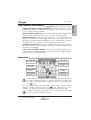
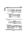
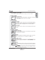
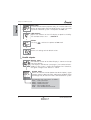
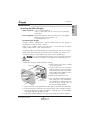
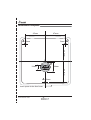
English
Français
Wind System
Deutsch
Entry Level
Nederlands
Espagñol
Italiano
Entry Level Wind System
Important
Suitability: the Entry Level Wind System is only recommended for use on
cruising boats up to 10.5m (35ft). For larger boats and for racing please
consider the mn100 Micronet Range.
If installing to a boat of aluminium, steel or Carbon Fibre construction,
please consult www.tacktick.com for installation advice.
Aid to navigation: like any other electronic instruments your Micronet
system is designed to serve only as an aid to navigation and it remains the
skippers responsibility to maintain a permanent watch and be aware of
developing situations.
Dismantling the product: any attempt to take a Micronet product apart
will invalidate the warranty.
Safety and disposal: do not dispose of any instrument in domestic waste.
Refer to regulations in force in your country. If in doubt return the instrument
to Tacktick Ltd. for correct disposal.
EMC conformance: All Tacktick equipment is designed to the best
industry standards for use in the recreational marine environment. The
design and manufacture of Tacktick equipment conforms to the
appropriate Electromagnetic Compatibility (EMC) standards. Correct
installation is required to ensure that performance is not compromised.
www.tacktick.com
Key Features
Completely wireless Wind Transmitter. The Wind Transmitter is solar
powered and requires no external power supply. It communicates wirelessly
with any Tacktick Micronet display.
Ultra low power requirement. The innovative Micronet technology means
the Entry Level Wind System draws just 1mA from the boats battery.
Simple installation. The only cable required is a connection from the
display to the boat’s electrical supply. There are no data cables to run and
absolutely no cables to go up and down the mast. No large holes to cut for
the display boss, just a small 1" (24mm) hole for the power cable.
Completely waterproof. All Tacktick products are completely waterproof
so there can be no misting of displays or leakages even if the products are
completely submerged.
Large, clear, analogue display. The Entry Level Wind Display with its
large wind arrow, intuitive functionality and high quality LCD digits provides
very clear, easy to read information.
Operation
Press and Hold to
Switch ON or OFF
Wind Angle
Pointer (Head)
Press to show
Apparent Wind
Press to show True
Wind
Wind Speed Units
indicator
Wind Speed
Display
Apparent/True
Wind indicator
Wind Angle
Pointer (Tail)
To allow your Wind Display to switch on automatically when the power
is turned on at the main panel, set the Master function in setup to ON
(see page 4). Tacktick recommend that the sytem is switched off using
the
key.
True Wind information is only available if speed data is present on the
Micronet network. Otherwise, pressing
will show “NO trU” for 5
seconds; the display will continue to show Apparent Wind information.
To obtain speed data you should install a Tacktick Speed and Depth
system (or a GPS and NMEA Interface).
www.tacktick.com
1
English
Key Features and Benefits
Entry Level Wind System
English
Keylock
When Keylock is enabled, the system is protected from accidental key
presses. To temporarily unlock the keys:
“KEY LOC” Indicates
the keys are locked
Press xxxxxxxxxx
Press xxxxxxxxx to
unlock the keys
Indicates the next key
to press
The keys re-lock after
one minute
Controlling the backlighting
Press and hold xxxxxx
Use x xxxxxxx & xxxx xxxx
to select level 1 to 3
Backlight control exits after
5 seconds
Setup
Setup operation
Press and hold xxxxxx
to enter Setup
Press xxxxxxxxx to
move to next Chapter
Use
&
to select Pages
You must go to the chapter
heading before changing chapter.
Editing setup data
To edit a value or
select from a list
To switch between two
alternatives
Press xxxxxxx to begin
Press xxxxxxx to switch
the setting
&
to set the value
xxxxxxx to confirm
2
www.tacktick.com
Setup Chapters and Pages
In the Page descriptions below, default settings are shown in bold.
Units chapter
Wind speed units
Sets the units in which Wind Speed is displayed. The options
are: KTS (Knots) or M/S (meters per second).
Wind chapter
Wind angle
A calibration function used to ensure the displayed apparent
wind angle is correctly aligned with the actual wind angle with
respect to the boat. See page 6 for the calibration process.
Wind speed
A calibration function used to ensure the displayed wind speed
is correct.
Options chapter
Auto networking
Used to add additional devices to the Micronet network.Refer
to www.tactick.com for details.
Keylock
Enables or disables the Keylock function, which can protect
against accidental presses. The options are: Off / On
Backlight control
Configures the display to control the system Backlighting or just
its own Backlighting. The options are: nEt (network) / LOC
(local).
Master
To configure your system to switch on automatically when the
power is switched on at the main panel, set to ON. The default
is OFF.
Warning: if you have more than one Micronet display you
must ensure that only one of these displays has the
Master parameter set to ON.
www.tacktick.com
3
English
Setup Chapters and Pages
Entry Level Wind System
English
Boat show
Used for demonstration purposes only, this function allows the
display of information when the Wind Display is NOT installed
as part of a Micronet system. The options are: Off / On.
LCD contrast
Adjusts the contrast of the LCD display to optimise visibility.
The available values are: 1 - 7, default 4.
Pointer
Pressing
switches the pointer tail on or off.
Reset
Returns all settings to their default values.
Health chapter
Display status
The software version of the Wind Display is shown on the top
line of the display.
If the display is the "Master" (see page 7), the number of items
(nodes) in the system is shown on the bottom line. Otherwise,
the signal strength to the "Master" is shown.
System status
Shows the software version (before the decimal point), signal
strength (after the decimal point) and battery condition (level
and charge rate) for the transmitters connected to the system
Text identifies the transmitters as follows:
HULL - Hull Transmitter
WIND - Wind Transmitter
NMEA - NMEA Interface
MAST - Mast Angle Sensor
MOB - Man overboard Transmitter
4
www.tacktick.com
Installation
English
Installation
Installing the Wind Display
Tools required: 5mm (3/16 inch) drill bit
24mm (1 inch) hole saw (or 12mm (1/2 inch) drill bit)
Power Drill
Parts supplied: Mounting Template (from the back of this user guide)
Mounting studs with thumbnuts (3)
Crimp receptacles (4)
Positioning the display
For best wireless performance, tacktick recommend that the display is
mounted on a GRP or acrylic surface.
Select a flat, smooth, surface that has access to the rear for the power
supply cable and the studs and thumbnuts.
If installing more than one display leave space between them for sun covers.
Avoid areas where damage may occur (winch handles, feet, warps etc.)
Check for clarity of vision and ease of access to the control keys.
Warning: it is recommended that displays are NOT positioned where
your arm must pass through the steering wheel to operate the keys.
Mounting
Position the Template carefully before starting.
1. Drill the three 5mm holes marked
Fixing stud
"A" on the template.
2. Using a hole saw cut the 24mm
hole marked "P" on the template.
Power
Connectors
Alternatively, drill two 12mm holes
and smooth them together. with a
Thumb nut
sharp knife or small file.
3. Remove the protective mask.
Power cables
4. Pass the power cable through the
Remove
hole and push the receptacles
protective mask
firmly onto the spades on the rear
of the display, taking care to
ensure the correct polarity.
5. Screw the three studs provided into the holes in the back of the display.
6. Place the display in position, pushing the three studs through the holes.
7. Secure the display using the thumbnuts, making sure it is level before
final tightening. Do not tighten hard.
8. Support the power cable by securing it to a fixing stud with a cable tie.
www.tacktick.com
5
English
Entry Level Wind System
Installing the Wind Transmitter
See the separate installation guide for the Wind Transmitter.
Calibration
After installation, the Wind Angle should be calibrated:
Motor the vessel directly into the wind.
Go to the Wind Angle page in Setup (see page 3)
Press
Use
and
to bring the lower larger digits to
000º. The upper smaller digits show the number of degrees of
offset entered.
Press
to exit Edit Mode
Press and hold
to exit Setup.
Maintenance
To clean, use only a damp, soft cloth. No detergents, solvents or abrasives
should be used. Use of chemicals will invalidate the warranty. Ensure the
sun cover is fitted to the instrument when cleaning the boat.
Fault Finding and Correction
Data is shown as dashes.
Communication between the Wind Transmitter and the Wind Display may
have been lost. Switch off the system, wait for thirty seconds and switch on.
Enter Setup (page 2) and scroll to the Health Chapter. Check the signal level
of the Wind Transmitter. '--.-' displayed means no communication from the
Wind Transmitter. A value after the decimal place will indicate a signal
strength 0-9, nine is strongest.
Wind speed is shown as zero.
If the anemometer cups are turning and the wind speed is shown as 0 then
there is a problem with your Wind Transmitter.
Lost Network alarm sounds
This can only occur if there is more than one Micronet display on your
network. The display showing the alarm has lost communication with the
Master. The display will power down shortly after sounding the alarm.
This may occur when powering down the system by switching off at the
breaker, this does not indicate a problem. In other cases, switch off the
system, wait for thirty seconds and switch back on.
6
www.tacktick.com
Specifications
The system behaves erratically after powering on.
This may occur if the breaker is switched off and rapidly back on, or if
is pressed on a display immediately after switching on the system
from the breaker. Switch off, wait for thirty seconds and switch back on.
For other problems
Contact your Tacktick Dealer/Distributor (see www.tacktick.com). providing
detailed information of the fault and your contact details. Other helpful
information required if possible: boat make/model/construction type and
current location plus a list of other Micronet items fitted.
Specifications
Height of digits:
14mm (0.55 inch)
Backlighting:
3 levels with daylight shutoff
System-wide or local control
Power supply:
9 to 30 volts DC
Power consumption:
1mA (5mA with maximum backlighting)
Units of display:
Wind Speed in Knots, Metres per Second
Alarms:
Audible Alarm for Lost Network
Weight:
Operating Temp.:
285g (0.63lbs)
-10o to +60oC (14o to 140oF)
Frequency:
868 MHz or 916 MHz
www.tacktick.com
7
English
The Master is the display with the Master setup parameter set to ON.
If no display has this parameter set, the display that was used to switch
on the system will be the master.
www.tacktick.com
Installation Template
47mm
A
47mm
5mm
5mm
42.5mm
C
L
P
12mm
24mm
52.5mm
A
Leave space for the Sun Cover
www.tacktick.com
5mm
A
*UU090 - r ev 02*