1
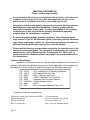
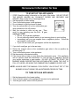
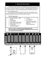
B10 SERIES BOILER
B3-B9
Boiler Manual And Installation
Instructions for Atmospheric Venting
Please Read Instructions Carefully
Save for Future Reference
WARNING
If the information in this manual is not followed exactly, a fire or
explosion may result causing property damage, personal injury or loss of
life.
DANGER
WHAT TO DO IF YOU SMELL GAS
· Do not try to light any appliance
· Do not touch any electric switch; do not use any phone in your
building
· Immediately call your gas supplier from a neighbor’s phone.
Follow the gas supplier’s instructions.
· If you can not reach your gas supplier call the fire department
Installation and service must be performed by a qualified installer,
service agency or the gas supplier.
Manufactured by:
Biasi S.p.A.
Verona, Italy
Distributed By:
QHT
QUINCY HYDRONIC TECHNOLOGIES, INC.
80 ROCHESTER AVE. SUITE #12
PORTSMOUTH, NH 03801
PHONE: 603-334-6400
FAX: 603-334-6401
Page 1
REV. H
Dear Customer:
Thank you for buying a QHT BIASI B10 Series Boiler.
The QHT BIASI B10 Series Boiler is a cast iron, oil or gas fired hot water boiler, using the
famous BIASI B10 (3-pass) design. The boiler is light, compact, simple, rugged and engineered
for maximum home heating efficiency.
We realize that it is not possible to answer all questions about the VEGA B10-series boiler
system in this manual. Reading this installation manual does not make the reader an expert in all
aspects of installation and operation, and does not replace the need for a qualified licensed
heating contractor. We urge you to contact your installing contractor or distributor if you are in
question about any aspect of your boiler's performance. Our main concern is that you are
satisfied with your boiler and its performance. We require that your contractor complete
efficiency tests using instruments.
The controls and accessories listed in this manual are intended to serve as guidelines rather than
specific recommendations. We realize that other makes and models of such devices are available
and can be used as successfully as those we specify. The installing contractor is the best judge of
a system's specific requirements, as well as the local availability of certain makes and models of
controls and accessories. The preceding does not apply, however, to the equipment that comes
with every boiler, such as the overheat control (L4006A or 7248U) and pressure relief valve.
The installation of the specific devices supplied with every boiler is absolutely necessary to
the safe operation of the boiler and protection of the heating system.
All BIASI Boiler blocks are built in accordance with the ASME boiler and pressure vessel code,
and bear the "H" stamp. The entire range of applications for the QHT BIASI B10 Series Boiler
have been tested to CAN/CGA B149 and are ULC compliant.
This BIASI B10 Boiler block has a limited lifetime warranty (refer to back of manual), a copy of
which is provided with the boiler. Please be sure to return the warranty registration card as the
warranty will be void without your boiler's serial numbers (located on the plate on the leg of the
boiler), date of installation and the name of your installer.
Thank you for purchasing our QHT BIASI B10 Series Boiler. If you have questions or
comments, please don't hesitate to contact us immediately. Our goal is 100% customer
satisfaction.
Sincerely,
Jim Quincy
QHT Inc.
Page 2
TABLE OF CONTENTS
QHT BIASI B10 Series
Section
Important Information &
Warnings
Page
4,5,6
General Information
1
7
Boiler Block Assembly &
Explosion Diagram
2
8
Boiler Location
3
9
Installation of Boiler
Trim Kit Components
4
10,11
Piping the Boiler
5
12
Intake Venting
6
13,14
Exhaust Venting
7
15
Common Exhaust Venting
7.1
15,16
Blocked Flue Switch
7.2
16
Gas Venting
7.3
17
8
18
Oil
8.1
19
Gas
8.2
20
Gas Line Piping
9
21
Boiler Jacket Assembly
10
22
Wiring
11
23-24
Oil Diagrams
11.1
25-28
Gas Diagrams
11.2
29-30
Commissioning the Boiler
12
31
Maintenance
13
31
Installer Notes
14
32
Burner Setup
Warranty
Inside Backcover
This installation manual is for the basic installation of a B10 series boiler for
atmospheric venting of oil and gas. If you are installing a direct vent
system, please refer to its addendum to be used in conjunction with this
manual to insure the proper installation of the boiler system.
Page 3
IMPORTANT INFORMATION
Please read this page carefully.
•
ALL BOILERS MUST BE INSTALLED IN ACCORDANCE WITH NATIONAL, STATE AND LOCAL
PLUMBING, HEATING AND ELECTRICAL CODES AND ORDINANCES, AS WELL AS THE
REGULATIONS OF THE SERVING ELECTRICAL, WATER AND GAS UTILITIES.
•
All systems should be designed by competent contractors, and only persons
knowledgeable in the layout and installation of heating systems should
attempt the installation of any boiler. It is the responsibility of the installing
contractor to see that all controls are correctly installed and operating
properly when the installation is completed.
•
Do not burn volatile garbage, gasoline, naphtha or other flammable liquids
other than No. 2 fuel oil. All flammable liquids (especially gasoline), chemicals,
rags, paper, wood scraps, debris, etc., should be kept away from the boiler at
all times. Keep the boiler area clean and free of all fire hazards.
•
Please read the literature and warranties supplied by the manufacturers of the
various accessory equipment. This equipment is warranted by the respective
manufacturers, not by Quincy Hydronic Technologies, Inc. Each piece of
equipment must be installed and used according to the recommendations of
the manufacturer.
Codes and Regulations:
Installation of the boiler, burner, oil tank and related equipment must conform to
national, state and local regulating agencies and codes applicable to the installation of
the equipment. In the absence of local requirements, the following codes apply:
A.
B.
C.
D.
E.
F.
G.
H.
NFPA
NFPA
NFPA
ANSI
ANSI
CAN/CGA
ANSI
CSA
- #31 Installation of Oil Burning Equipment
- #70 National Electric Code
- #211 Chimneys and Vents
- #Z223.1 National Fuel Gas Code
- Domestic Gas Conversion Burner
- B149 Installation Codes
- CSD-1
-C22.1 Canadian Electrical Code, Part1
The above codes are available from:
National Fire Protection Association (NFPA)
Battery March Park
Quincy, MA 02269
http://www.nfpa.org
Page 4
CSA International
8501 East Pleasant Valley Road
Cleveland, OH 44134
http://www.csa-international.org
WARNING
Any appliance that burns natural gas, propane gas, fuel oil, or coal is capable of
producing carbon monoxide (CO). Carbon Monoxide (CO) is a gas which is
odorless, colorless and tasteless but is very toxic. CO is lighter than air and thus
may travel throughout the building.
BRIEF EXPOSURE TO HIGH CONCENTRATIONS OF CO, OR
PROLONGED EXPOSURE TO LESSER AMOUNTS OF CO MAY
RESULT IN CARBON MONOXIDE POISONING. EXPOSURE CAN
BE FATAL AND EXPOSURE TO HIGH CONCENTRATIONS MAY
RESULT IN THE SUDDEN ONSET OF SYMPTOMS INCLUDING
UNCONSCIOUSNESS.
Symptoms of CO poisoning include the following:
dizziness
vision problems
headache
loss of muscle control
nausea
weakness
shortness of breath
unclear thinking
unconsciousness
The symptoms of CO poisoning are often confused with those of influenza, and the
highest incidence of poisoning occurs at the onset of cold weather or during flu
season. A victim may not experience any symptoms, only one symptom, or a few
symptoms. Suspect the presence of carbon monoxide if symptoms tend to
disappear when you leave your home.
The following signs may indicate the presence of carbon monoxide:
•
•
•
Hot gasses from appliance, venting
system pipes or chimney, escaping into
the living space.
Flames coming out around the appliance.
Yellow colored flames in the appliance.
•
•
•
Stale or smelly air.
The presence of soot or carbon in or
around the appliance.
Very high unexplained humidity inside
the building.
IF ANY OF THE SYMPTOMS OCCUR, OR IF ANY OF THE SIGNS OF CARBON
MONOXIDE ARE PRESENT, VACATE THE PREMISES IMMEDIATELY AND
CONTACT A QUALIFIED HEATING SERVICE COMPANY, THE GAS COMPANY
OR THE FIRE DEPARTMENT.
ONLY QUALIFIED, LICENSED SERVICE CONTRACTORS SHOULD PERFORM
WORK ON YOUR B-10 BOILER.
Page 5
Homeowner Information for Gas
TO START UP THE APPLIANCE
1. STOP! Read the safety information on the side of the boiler. DO NOT START
THE BOILER UNLESS ALL CLEANOUT DOORS ARE SECURED AND
SEALED. (Skip to step 9 for oil burning boilers)
2. Set thermostat to lowest setting
3. Turn off all electric power to the appliance
4. Do not attempt to light the burner by hand
5. Turn the manual shut off on the combination gas
valve clockwise to the off position.
6. Wait five minutes to clear out any gas. Then
smell for gas, including near the floor. If you
smell gas, STOP!
• Do not try to light any appliance
• Do not touch any electric switch; do not use any phone in your building
• Immediately call your gas supplier from a neighbor’s phone. Follow the
gas supplier’s instructions.
• If you can not reach your gas supplier call the fire department
7. If you don’t smell gas, go to the next step.
8. Return the manual valve on the combination gas valve to the on position by
reversing step “5”.
9. Turn on all electric power to the appliance.
10. Set thermostat to the desired setting.
11. If the burner fails to light you may press the reset button once. If the appliance
will not operate, follow the instructions “To Turn Off Gas To Appliance” and call
your service technician or gas supplier. DO NOT ATTEMPT TO START THE
BURNER WHEN EXCESS GAS HAS ACCUMULATED, WHEN THE UNIT IS
FULL OF VAPOR, OR WHEN THE COMBUSTION CHAMBER IS VERY HOT.
NOTE: ALWAYS KEEP THE MANUAL FUEL SUPPLY VALVE SHUT OFF IF THE
BURNER IS SHUT DOWN FOR AN EXTENDED PERIOD OF TIME.
TO TURN OFF GAS APPLIANCE
1. Set the thermostat to the lowest setting.
2. Turn off electric power to the appliance if service is to be performed.
3. Turn the gas control valve to the off position.
.
Page 6
1. General Information
The BIASI B 10-series boilers are wet base design, sectional, cast-iron boilers
for forced hot water heating systems. The boilers are shipped pre-assembled from
the factory in lengths from three to nine sections. They are designed for firing with
oil or gas power burners, which are packed separately along with the jacket and
controls for shipping purposes.
When the boiler is received, check the contents to ensure that there is no
shortage or damage to any part of the boiler system. With every boiler you should
receive a boiler block, jacket, trim kit and a burner (oil or gas).
Trim Kit Components
1 - Honeywell L4006A or 7248U
aquastat
1 – Immersion well
1 – ¾” X 3” Nipple
1 – Combo pressure/temp gauge
1 – 30 PSI Pressure relief valve
1 – ¾” Boiler drain
1 – Cera-fiber Pad for floor of
combustion chamber
2 – ¾” Plugs
1 – ¼” X ½” Bushing
1 – ¾” 90° Elbow
1 - Double acting barometric
damper with manual reset
spill switch
(Gas systems only)
USE ONLY THE UL LISTED BOILER COMPONENTS AND
UL/CSA LISTED OIL OR GAS BURNER COMPONENTS SUPPLIED WITH
THE VEGA B10 BOILER SYSTEM.
Gross Input Burner
Heating
Capacity
Net Output
Capacity
MBH
GPH- Oil MBH- Gas
OIL
GAS
B-13
67
0.55
80
58
60
B-14
110
0.90
115
96
84
B-15
124
1.00
140
108
103
B-16
153
1.25
175
133
129
B-17
185
1.50
215
161
157
B-18
211
1.80
257
183
189
B-19
257
2.10
298
223
219
Maximum Water Working Pressure 58 psi
Boiler
Model
Flue Gas
Water Length
Resistance Efficiency Content
(L)
Weight
IN. W.C.
%
GALS.
IN.
LBS
0.03
86.6
3.5
15.5
249
0.04
85.8
4.7
19.5
308
0.06
87.2
5.7
23.5
367
0.07
86.7
6.7
28.5
427
0.08
86.8
7.7
33.5
486
0.1
86.8
8.8
38.5
546
0.12
86.5
9.9
42.5
606
Maximum Relief Valve is 30 psi at 500 MBH
All dimensions are in inches.
29 3/4
L
Page 7
18 3/4
2. Boiler Block Assembly
All QHT BIASI B10 Series Boilers are shipped from the factory in assembled
boiler blocks. If, however, the block needs to be split into sections for ease of
delivery, please read the following:
To assemble split blocks, move sections into parallel and facing each other.
Sections may be slid along boards placed underneath the sections. Inspect nipple
ports for damage or burrs. Remove any burrs by scraping the port very lightly. Wipe
the push nipples and nipple ports with a clean cloth. Apply a film of nipple compound
to both the nipple and port. Install the nipple in the port and then seal by hitting with
a hammer cushioned with a block of wood. Apply section sealant to one section only
and slide sections together. Install the four draw rods and draw the sections together
evenly (measure with yardstick). Draw the sections together until sections make
iron-to-iron contact at a point around the top and bottom ports of each section.
DO NOT OVER TIGHTEN DRAW RODS
NOTE: When cutting off excess length of draw rods, allow enough length to install
boiler jacket on the draw rods.
Boiler Components & Parts
BIASI B - Series
Boiler Block Assembly:
1 Front Section
2 Rear Section
3 Intermediate Section
4 Steel Push Nipples
5 Tie Rod
6 Tie Rod Nut
7 Tie Rod Washer
8 1 1/2" X 3/4” Bushing
9 Plug gasket
10 1/2" X 1 1/2" Bushing
11 Boiler Swing Door
12 Front Door Upper Insulation
13 Front Door Upper Gasket
14 Front Door Upper Plate
15 Front Door Lower Insulation
16 Front Door Stud (Qty 7)
17 Front Door Lower Gasket
18 3/4" Plug (Sight Hole)
19 Boiler Door Hinge (4 pieces)
20 Hinge Pin (Qty 6)
21 Boiler Body Hinge Bolts (Qty 2)
22 Door Hinge Mounting Bolts (Qty 2)
23 6 inch Boiler Breeching
24 Upper Front Fixed Door
Page 8
3. Boiler Location
The following are the minimum clearance to construction or combustible materials:
9”
1. 9” from the top, sides,
and rear of the boiler.
2. 18” from the flue pipe in
any direction.
3. 24” from the front of the
boiler.
24”
9”
DANGER
The boiler must be located on a non-combustible floor. A smooth, level
concrete floor is recommended. Locate the boiler as close as possible to the
chimney. If boiler is installed on combustible flooring, consult local authorities for
proper method of covering floor. The boiler must not be installed on carpeting.
Caution: Do not store or use flammable materials, chemicals or
flammable liquids, especially gasoline, in the vicinity of this heating
appliance.
If the boiler is to be installed in a "direct vent" configuration, please refer to the B10
Direct Vent Addendum supplied with the Direct Vent Kit.
PROVISIONS FOR COMBUSTION AIR AND VENTILATION AIR MUST BE IN
ACCORDANCE WITH SECTION 5.3, “AIR FOR COMBUSTION AND
VENTILATION”, OF THE NATIONAL FUEL GAS CODE, ANSI Z223.1, OR
APPLICABLE PROVISIONS OF THE LOCAL BUILDING CODES. DO NOT
INSTALL THE BOILER UNTIL PROPER COMBUSTION AIR HAS BEEN
ARRANGED.
WARNING
Boiler is certified as an indoor appliance. Do not install boiler outdoors or locate
where it will be exposed to freezing temperatures
Page 9
4. Installation of Boiler Trim Components
Trim Kit Components
1 - Honeywell L4006A or 7248U
aquastat
1 – Combo pressure/temp gauge
1 – ¾” X 3” Nipple
1 – 30 PSI pressure relief valve
1 – ¾” Boiler drain
1 – Cera-fiber Pad for floor of
combustion chamber
1– ¼” X ½” Bushing
2 – ¾” Plugs
1 – ¾” 90° Elbow
1 – Immersion well
1- Double acting barometric
damper with manual reset spill
switch (Gas systems only)
USE ONLY THE ULC LISTED BOILER COMPONENTS AND
UL/CSA LISTED OIL OR GAS BURNER COMPONENTS SUPPLIED WITH
THE QHT BIASI B10 SERIES BOILER SYSTEM.
Please refer to figures below for Barometric Damper location for either oil or gas
and to the next page for the proper location of the trim components.
BAROMETRIC DAMPER
WITH MANUAL RESET
SPILL SWITCH
ALTERNATIVE
DAMPER LOCATION
BIASI B10
BIAS
GAS COCK
POWER GAS
BURNER
DRIP LEG
Heat Wise
GAS TRAIN
P
UNION
NOTE: See Page 19 for
available gas burners in
North America
4. Installation of Boiler Trim Components Cont.
1. Install L4006A aquastat in upper left or right rear tapping using 3/4” immersion
well. All tapings and joints should be sealed with piping compound. The L4006A
can be adjusted up to 220o F, and should be set to the desired temperature by
the installer. The differential is also adjustable between 5 and 30 degrees. It
should be set as close to 30 degrees as possible to prevent short cycling of the
boiler. If you are installing a 7248U, Screw the unit to side panel of the boiler as
close to the immersion well as possible using the tabs on the aquastat. Run the
sensor from behind the aquastat to the immersion well and fix it according to
Honeywell’s instructions. The 7248 can be adjusted between 140o F and 220o F
with a fixed differential of 30 degrees.
2. Install Pressure Relief Valve in opposite, upper rear tapping using 3” nipple and
3/4” elbow
3. Install 3/4” boiler drain in lower left or right rear tapping, or lower front tapping.
4. install 3/4” plug in opposite lower rear tapping, and/or the other plug in lower front
tapping of the boiler.
5. Install combination pressure/temperature gauge and 1/2” x 1/4” bushing in upper
front tapping. The gauge must be tightened using a wrench and not your
hand.
6. Install burner mounting hardware in the four tapings on the front of the boiler
door.
7. Install boiler door bolts on opposite side of door hinge.
Boiler Tapping Diagram:
1 Supply Tapping
Ø12
1 Pressure/Temperature Guage Tapping
Ø2
Ø3
4 PRV or Hi Limit Control Tapping
Ø3
4 Hi Limit Control or PRV Tapping
Ø6 Exhaust Breeching
1 Burner Blast Tube Orifice
Ø32
3X 27
27
22
1
112
1
42
Ø3
4 Alternative Boiler Drain Tapping
Ø3
4 Alternative Boiler Drain Tapping
1 Return Tapping
Ø12
Ø3
4 Boiler Drain Tapping
33
4
1
2X 42
Page 11
5. Piping the Boiler
All piping must conform to state and local codes. Page 11 shows the location
and size of the boiler tappings. It is recommended to install unions and gate valves
at the inlet and outlet of the boiler, so it may be readily isolated for service.
For Canadian installations, a low water cut off is required if the boiler is
installed above the level of radiation. Even if the boiler is installed below the level of
radiation it is strongly recommended that a low water cut off be installed. Install
manual and/or automatic air venting devices at the high points in the system to
eliminate trapped air. The weight of all piping should be supported by suitable
hangars and floor stands, not by the boiler’s purging/expansion station. Clearance
for hot water pipes are 1 inch to combustibles. The make-up water line must be
piped into the boiler and be fitted with a backflow preventer and a pressurereducing valve to reduce line pressure to 10 to 15 psi.
In the case of a gas installation, the boiler should be installed such that the
gas ignition system components are protected from water (dripping, spraying, etc.)
during appliance operation and service (circulator replacement, condensate trap,
control replacement, etc.).
If the boiler is to be used in conjunction with a chilled water system, it must be
piped with the appropriate valves to ensure the chilled medium does not enter the
boiler. If the boiler is connected to heating coils in an air handling system, where the
coils could be exposed to cold air circulation, provisions for freeze protection control
must be installed. The boiler must have flow control valves or other automatic
means to prevent gravity circulation of the boiler water during the cooling cycle.
NOTE: If the heating system is to be filled with antifreeze, use only formulations expressly made for
hydronic heating systems (such as propylene glycol). Do not use automotive types of antifreeze
(ethylene glycol). Use of antifreeze will alter system output and characteristics. Consult a factory
representative for details or assistance.
SAFETY RELIEF VALVE
1. The safety relief valve should be piped into one of the two upper tapings in the
rear of the boiler
2. The relief valve should be installed using the hardware supplied in the trim kit
without valving between the PRV and the boiler.
3. Pipe the discharge for the safety relief valve with copper tube to within four
inches from the floor to prevent injury in the event or a pressure release. Provide
piping that is the same size as the safety relief valve outlet.
Page 12
6. Intake Venting
1. Be certain adequate air is available for combustion and ventilation.
a.) Boiler located in unconfined space:
Installation in large areas, such as basements, can usually be assumed to
provide sufficient air.
b.) Boiler located in confined space : (See Figure A.)
If all air for combustion and ventilation is to come from within the building:
Two (2) openings shall be provided with one (1) opening commencing within
12 inches of the ceiling and one (1) opening commencing within 12 inches of
the floor of the enclosure. These openings shall not be located closer than 3
inches from either the top or bottom of the enclosure and shall be open to
areas connecting freely with the outdoors. The area of each opening shall
not be less than one square inch per 1000 BTU/HR. of total input rating of all
appliances within the enclosure; with a minimum of 100 square inches for
each opening.
If all the air for combustion and ventilation is to come from outside the
building: Two (2) openings shall be provided with one opening commencing
within 12 inches of the top and an opening commencing within 12 inches of
the bottom of the enclosure. These openings shall not be located closer than
3 inches from either the top or bottom of the enclosure, and shall connect
directly or by ducts with the outdoors. The area of each opening shall be
equal to one square inch per 4000 BTU/HR of total input rating. If ducts are
used to convey the air, vertical ducts require areas of one square inch per
4000 BTU/hr. Horizontal ducts require one square inch per 2000 BTU/hr.
Ducts shall have the same cross sectional area as the full area of the louver
openings.
The upper opening is essential for maintenance of proper air
circulation with the boiler and of reasonable ambient temperature to maintain
proper control temperatures. When a duct is used for ventilation, check for
louver free net area and correct for screen resistance to ensure that the
sufficient ventilation area has been satisfied. DO NOT INSTALL THE
BOILER UNTIL PROPER COMBUSTION AIR HAS BEEN ARRANGED.
Page 13
6. Intake Venting Cont.
c.) Boiler located in a room under negative pressure:
If the boiler is to be installed within a home where the operation of exhaust
fans, attic fans, kitchen ventilation systems, clothes dryers or fireplaces may
create severe negative vent pressures causing unsatisfactory combustion and
venting, special provisions should be made for additional make-up air to
supply the other air requirements. If building is of tight construction,
combustion air requirements may not be met and combustion air ducts from
outside may be necessary. Please refer to NFPA No. 31.
Tight Construction (as defined by ANSI Z223.1):
1. Walls and ceilings exposed to the outside atmosphere have a
continuous water vapor retarder with a rating of 1 perm or less with
openings sealed with gaskets, etc..
2. Weather-stripping has been added on open able windows and doors,
and caulking or sealants are applied to areas such as: joints around
windows and door frames, between sole plates and floors, between wallceiling joints, between wall panels, at penetrations for plumbing,
electrical, and gas lines, and in other openings.
If the building is of tight construction, air openings must be provided from the
outside, with appropriate sizing depending on amount of BTU/H as shown in
pictures. The boiler room must never be under a negative pressure, even if
the appliance is installed as direct vent. Always provide air openings sized
not only to the dimensions required for the firing rate of all appliances, but
also to handle the air movement rate of the exhaust fans or air movers using
air from the building or boiler room.
Figure A.
Page 14
7. Exhaust Venting
The B10 boiler is a high efficiency unit that requires proper venting. The boiler must
be vented to the outdoors by means of a tile lined masonry or a approved pre-fabricated
chimney of the size and height recommended by the manufacturer or by a listed "power
venting" unit which provides draft by mechanical means. In many installations, particularly
older interior and most exterior chimneys, a corrosion resistant liner should be installed and
may be required by code. Please consult liner manufacturer for the appropriate chimney
liner.
The chimney discharge opening must be located at least 24 inches above any part of
the building structure within 4 feet of the chimney. Be sure the chimney and smoke pipe
won't become obstructed by squirrels, bird nests, soot buildup, chimney liner deterioration,
etc.. If using a "power venter" system, it is suggested that it should be installed on the
leeward side of the house. (Please consult with manufacturer of "power venter" for
requirements concerning clearances from combustibles and distances from doors and
windows.) The "venter" must be installed by a licensed burner mechanic and done in
accordance with local codes. This is a very low stack temperature boiler (350F gross temp.)
so caution should be used when connecting to an outside built chimney. Should you have
concern that the flue gases could condense, then you should consider lining the chimney or
using a listed, "power venting" or " direct venting unit". If "power venting" is used to
discharge flue gases, then the power vent unit should be equipped with a postpurge control
such as a delay-off, timing control to prevent problems with fogging and nozzle post drip.
The exhaust pipe connection from the boiler to the chimney should be as short as
possible, with a minimum number of elbows. The vent pipe must have a vertical rise of at
least 1/4 inch per foot of horizontal run. The vent pipe must be of the same diameter as the
flue outlet on the boiler. The chimney connector should have a minimum thickness of 26
gauge, corrosion resistant (galvanized) steel, and be assembled with a minimum of three (3)
sheet-metal screws in each joint. In some one and two story houses, a barometric draft
control isn't required as the B-10 is designed to be pressure-fired. However in high draft
situations which exceed the flue gas resistance through the boiler, a barometric draft control
is recommended. The over fire draft should be positive and between 0 and .06 inches of
water column. The draft at the breech should be enough to overcome the resistance
through the boiler.
7.1 Common Exhaust Venting Cont.
Common vent exhaust:
If this boiler is replacing one that was part of a common venting system, it is
likely that the vent is to large to vent the appliances still attached to it. To prevent this,
at the time of removal, the following steps shall be followed with each appliance remaining connected to the common venting system. Place each appliance in operation, while the other appliances remaining connected to the common venting system
are not in operation.
1.Seal any unused openings in the common venting system.
2.Visually inspect the venting system for proper size and horizontal pitch and determine there is no blockage or restriction, leakage, corrosion and other deficiencies
which could cause an unsafe condition.
Page 15
7.1 Common Exhaust Venting Cont.
3.Insofar as practical, close all building doors and windows and all doors between
the space in which the appliance remaining connected to the common venting
system is located and other spaces of the building . Turn on any appliance not
connected to the common vent system. Turn on all exhaust fans except for
summer exhaust fans. Close the fireplace damper if applicable.
4.Place in operation the appliance being inspected. Follow the lighting instructions.
Adjust thermostat so appliance will operate continuously.
5.Test for spillage at the barometric damper opening after 5 minutes of main burner
operation. Use the flame of a match or candle, or smoke from a cigarette, cigar or
pipe.
6.After it has been determined that each appliance remaining connected to the
common venting system properly vents when tested as outlined above, return the
doors, windows, exhaust fans, fireplace dampers and any other gas-burning
appliance to their previous condition of use.
7.Any improper operation of the common venting system should be corrected so
the installation conforms with the National fuel Gas Code, ANSI Z223.1 and/or
CAN/CGA B149, Installation Codes. When resizing any portion of the common
venting system, the common venting system should be resized to approach the
minimum size as determined using the appropriate tables in Part 11 of the
National Fuel Gas Code, ANSI Z223.1, and/or CAN/CGA B149, Installation
Codes.
7.2 Blocked Flue Switch:
1. Pierce a 5/8” hole into the vent pipe near the appliance outlet. Remove one of the securing
nuts from the pipe of the safety switch. Tighten the other securing nut onto the pipe as far
as possible.
2. Insert the threaded pipe end into the pierced hole, then install the securing nut, then install
the securing nut, which was removed in step 1, and tighten securely.
3. Please consult the wiring section of this manual for the wiring of the blocked flue switch.
Page 16
7.3 Gas Venting
For boilers connected to gas vents or chimneys, vent installations shall be in
accordance with part 7, Venting of Equipment, of the National Fuel Gas Code, ANSI
Z223.1 or Section 7, Venting Systems and Air Supply for Appliances, of the CAN/
CGA B149, Installation Codes, or applicable provisions of the local building codes.
Vent connectors serving appliances vented by natural draft shall not be
connected into any portion of mechanical draft systems operating under positive
pressure.
Page 17
8. Burner Setup
Good, reliable operation with a minimum of service, starts with attention to the small
details:
Oil:
1. Setting the nozzle position and electrodes "by the book" using the
manufacturer's gauges.
2. Installing a quality micron filter at the burner.
3. Making careful/tight flare connections, without couplings, on oil suction
line.
4. Checking fuel pump pressure.
5. Checking draft at the breeching to insure it is adequate to overcome flue
gas resistance. (-.02 to –.04 in. w.c.)
6. Setting the air band properly with well maintained instruments. A good
target is 11% to 12.5% of (CO2) or 6.5% to 3.8% of (O2).
To ensure proper burner setup, gauges should be used to check things such as the
pump pressure, CO2 levels, etc…
Gas:
1. Checking the electrode, orifice size, and flame rod settings against
manufacturer’s specs to insure proper operation.
2. Installing properly sized gas piping according to BTU input required and
length of gas line run.
3. Making sure there is proper manifold pressure before and after the
gas valve using a calibrated manometer.
4. Checking draft at the breeching to insure it is adequate to overcome flue
gas resistance. (-.02 to –.04 in. w.c.)
5. Setting the air band properly with well maintained instruments. A good
target is 9.5% to 10.5% of (CO2) or 5% to 2.5% of (O2) for natural gas, or
10.0% to 12.0% of (CO2) or 5% to 2.5% of (O2) for LP gas.
TRIMINSULATION
INSULATION IN BLAST
CUT
BOILER
DOOR OPENING
TUBE
OPENING
TO 4.25"
TO
4.25”
FOR
BECKETT
AFG
TO ACCEPT CARLIN BLAST
BLAST TUBE.
TUBE.
Page 18
8.1 Oil Burner Setup
This page is only for boilers using an oil burner. If a gas burner is being used,
please refer to page 19 for the proper setup of the burner and gas lines.
BURNER MANUFACTURER:
Boiler Model
Burner Model
Firing Rate
Insertion Depth
Nozzle
Spray Pattern
Pump Pressure
Head Type
Head Position
B-3
NEC-1102*
0.55
3.50"
0.50 X 60
hollow
180 psi
NX70LC
0.75
BURNER MANUFACTURER:
Boiler Model
Burner Model
Firing Rate
Insertion Depth
Nozzle
Spray Pattern
Pump Pressure
Head Type
Head Position
B-4
NEC-301*
0.8
2.75"
0.65 X 60
hollow
160 psi
6 slot
3
BURNER MANUFACTURER:
Boiler Model
Burner Model
Firing Rate
Insertion Depth
Nozzle
Spray Pattern
Pump Pressure
Head Type
Air Shutter
Air Band
B-3
NEC 1301
0.55
2.75"
0.50 x 60
Solid
180 psi
L1
8.0
0.0
Beckett NX
B-4
NEC-1101*
0.90
6.00"
0.65 X 60
solid
180 psi
NX90LB
2.75
B-5
NEC-1101*
1.00
6.00"
0.75 X 60
solid
180 psi
NX90LB
3.75
B-6
NEC-1103*
1.20
6.00"
0.90 X 60
W
180 psi
NX90LB
3.75
B-6
NEC-303*
1.25
2.75"
1.00 X 60
solid
160 psi
9 slot
5
B-7
NEC-303*
1.5
2.75"
1.10 X 60
Solid
185 psi
9 slot
6
B-5
NEC 1303
1.00
6.0"
0.75 X 60
Solid
175 psi
V1
7.0
0.0
B-6
NEC 1304
1.25
3.5"
1.10 X 60
Solid
125 psi
V1
10.0
1.0
Beckett AFII
B-5
NEC-302*
1
2.75"
0.85 X 60
solid
140 psi
6 slot
4
Beckett AFG
B-4
NEC 1302
0.80
2.75"
0.75 X 60
Solid
150 psi
L1
10.0
0.0
BURNER MANUFACTURER
Pioneer
Boiler Model
B-3
Burner Model
P-1 FV(1)
Firing Rate
0.55
Nozzle
0.40 X 80
Spray Pattern
Solid
Pump Pressure
190
Head Setting
1
Air Setting
0
1) 120-mm Fan Needed
B-3
F-3
0.55
3.0"
0.50 X 80
W
145 PSI
1
2-2.7
B-7
NEC 1304
1.50
3.5"
1.35 X 60
Solid
125 psi
V1/2 Setting
10.0
3.0
Heat Wise
B-4
P-1 KA
0.90
0.65 X 70
Solid
190
1
9.5
BURNER MANUFACTURER
Boiler Model
Burner Model
Firing Rate
Insertion Depth
Nozzle
Spray Pattern
Pump Pressure
Turbulator
Air Gate
*The highlighted burners are
not listed by ULC and may
not be installed on Biasi
equip ment in Canada.
B-5
P-1 KA
1.00
0.85 X 70
Semi Solid
140
1
16.5
B-6
P-2 KA
1.25
1.00 X 80
Hollow
155
3.75
6
B-7
P-2KA
1.50
1.25 X 80
Hollow
145
6
11
B-8
P-2KA
1.8
1.5 X 80
Hollow
145
10.75
6
B-9
P-2KA
2.1
1.75 X 70
Solid
140
14.25
11
B-6
F-5
1.25
3.0"
1.00 X 60
W
145 PSI
3
3-5
B-7
F-5
1.50
3.0"
1.25 X 60
W
145 PSI
4
4.5-6
B-8
F-10
1.80
3.0"
1.50 X 60
B
145 PSI
2
2.8-3.4
B-9
F-10
2.10
3.0"
1.75 X 60
B
145 PSI
3
3-4.1
Riello F-40 Series
B-4
F-3
0.80
3.0"
0.65 X 80
W
145 PSI
2
3.5-4.5
B-5
F-5
1.00
3.0"
0.85 X 60
W
145 PSI
2
2.8-.3.4
Page 19
8.2 Gas Burner Setup
This page is only for boilers using a gas burner. If an oil burner is being used,
please refer to page 18 for the proper setup of the burner.
Natural Gas
Riello
Boiler Model
Burner Model
B-4
Propane
R200
Input
(MBH)
110
Man. Pres.
(W.C.)
1.06”
Head
Setting
2.2
Air
Gate
1
Man. Pres.
(W.C.)
1.32”
Head
Setting
2
Air
Gate
1
B-5
R200
140
1.20”
2.8
2
1.76”
2.7
2
B-6
R200
175
1.46”
2.8
3
2.34”
2.9
3
B-7
R400
207
1.22”
2
0
1.48”
2
0
B-8
R400
248
1.26”
2.3
1
1.64”
2.3
1
Natural Gas
Heat
Wise
Boiler
Model
Burner
Model
B-3
SU-2A
80
B-4
SU-2A
115
B-5
SU-2A
B-6
SU-2A
B-7
B-8
B-9
Input Man. Pres.
(MBH)
(W.C.)
Propane
Head
Setting
Air
Gate
Orifice
Man.
Pres.
(W.C.)
Head
Setting
Air
Gate
Orifice
3.5”
18
closed
3/16
2.0”
22
closed
3/16
3.5”
12
3
7/32
2.3”
12
3
7/32
140
3.2”
15
8.3
9/32
1.8”
15
7.75
9/32
175
3.5”
10
13.5
21/64
2.3”
10
13.5
21/64
SU-2A
215
3.3”
3
15
27/64
2.0”
3
15
27/64
SU-3
272
1.7”
1
3.25
No orifice
1.3”
1
3.25
No orifice
SU-3
308
2.3”
1
6.75
No orifice
1.7”
2
6.5
No orifice
*Note: These burners may not be used on Biasi equipment in Canada
Note: Consult burner manufacturers literature for gas manifold diagram and controls.
To determine how much gas is coming into the
burner, or to set the gas meter correctly, the
following formula can be used.
Ft3/hr = [3600/(sec. Per rev.)]*(Size of gas meter)
The chart to the right can be used to determine
the flow rate depending upon the time per
revolution and the size of the gas meter dial.
Page 20
Seconds per
Revolution
20
25
30
35
40
45
50
55
60
0.5
90
72
60
51
45
40
36
33
30
Size of Gas Meter Dial
(Cubic Foot)
1
2
180
360
144
288
120
240
103
206
90
180
80
160
72
144
65
131
60
120
9. Gas Line Piping
Gas supply piping is to be sized and installed properly in order to provide a
supply of gas sufficient to meet the maximum demand without undue loss of
pressure between the meter and the boiler. Consult with the National Fuel Gas
Code ANSI Z223.1 for proper sizing of gas piping for various lengths and diameters.
Locate a drop pipe adjacent to, but not in front of the boiler. Locate a tee in the
drop pipe at the same elevation as the gas inlet connection to the boiler. Extend the
drop line with a nipple towards the floor and cap to form a sediment trap. Install a
shut off valve before the tee with sediment trap and a union after the tee before the
combination gas valve.
When installing the boiler, make sure a pipe compound resistant to the action of
liquefied petroleum is used. Check piping for leaks. Always check leaks with a water
and soap solution. DO NOT USE A FLAME FOR CHECKING GAS LEAKS
The boiler and its individual shut-off valve must be disconnected from the gas
supply piping during any pressure testing of that piping at test pressures in excess of
1/2 psi.
INSTALLATION OF SEDIMENT TRAP AND BURNER SUPPLY
Direction of flow
To check for gas
leaks, use a gas detector or apply a soap
solution to the joints.
DO NOT USE AN
OPEN FLAME!
Manual Shutoff Valve
Height of shutoff valve above ground
level to conform to local codes, if any.
Note: Massachusetts state code requires
gas shutoff to be a tee handled gas cock.
Pressure Gauge Port
(1/8” NPT plugged)
1” X 1” X 3/4” Tee
3” MINIMUM
Male Union 3/4” NPT
Burner Gas Train
Pipe Cap
Page 21
10. Boiler Jacket Assembly
NOTE: All piping, boiler controls, gauges and valves should be installed before the
jacket is assembled on the boiler. Below is an explosion view of the boiler and
jacket assembly to clarify these boiler jacket assembly instructions. Insert the
separate (loose) piece of insulation on top of boiler with the foil side facing in so the
entire top, bottom and sides of boiler are covered. Place tubular jacket spacers (#35
& #36 on exploded view of boiler) on the upper and lower draw rod extensions at the
front(long spacers) and rear(short spacers) of the boiler. Place the rear insulated
jacket panel (#26) at the back of the boiler, also by slipping over the slotted cut-outs.
Position side jacket panels (#38 & #25) by slipping the slotted cut-outs over the
boiler draw rods. Place the lower front jacket panel (#28) in place and secure with
self-tapping screws provided. Fasten the washers and hex nuts to the ends of the
tie-rods to hold the jacket in place. Set the top panel (#27) in place and secure with
two screws in the back of the panel. With the jacket firmly secured, place front panel
(#37) in position on the tabs on the side panels and press firmly to snap spring
connectors in place.
NOTE: Do not attach any electrical wiring or electrical conduit or boiler piping to the
top panel (#27).
Note: For replacement parts, contact your local Biasi Wholesaler.
Boiler Jacket Assembly:
25 RH Side Jacket Panel
26 Rear Jacket Panel *
27 Top Jacket Panel
28 Lower Front Jacket Panel
29 Top & Side Insulation
30 Front Panel Pin Clips
31 Self Tapping Screws (Qty 2)
32 Jacket Mounting Nut (Qty 8)
33 Jacket Mounting Washer (Qty8)
34 Front Panel Mounting Pins
35 Long Jacket Spacer (Qty 4)
36 Short Jacket Spacer (Qty 4)
37 Front Jacket Panel *
38 LH Side Jacket Panel
* Supplied with attached insulation
P
11. Wiring
The electricity to the boiler shall come from a dedicated breaker in the electric
service box. A service switch should be mounted on the side of the boiler so the
burner technician can service the burner and controls. The electrical wiring should
be routed so as not to interfere with normal servicing of the boiler. Wiring done in the
field between devices not attached to boiler shall conform with the temperature
limitations for type T wire (63F/35C) or other specified wire as applicable when
installed in accordance to manufacturer's instructions and wiring diagrams.
If an external electrical source is utilized, the boiler, when installed, must be
electrically bonded to ground in accordance with the requirements of the authority
having jurisdiction or, in the absence of such requirements, with the National
Electrical Code, ANSI/NFPA 70 and/or the Canadian Electrical Code Part 1, CSA
C22.1, Electrical Code.
Since the boiler is equipped with a swinging burner door, the supplied 48”
long burner wiring harness with 4-prong quick disconnect plug needs to be used.
The short end of the wiring harness needs to be wired to the burner following the
respective burner wiring diagram in the subsequent pages of this manual. The long
end of the wiring harness needs to be wired into the burner service switch located at
the installers discretion.
Refer to pages 19 to 23 for oil wiring diagrams and pages 24 to 25 for gas wiring
diagrams.
Page 23
11. Wiring
4006A
WIRING
7248U
WIRING
7248U WIRING PROCEDURE
If you received a Honeywell 7248U with your Biasi boiler, you will need to make the changes
shown above, and described below to the wiring diagrams.
1.
2.
3.
4.
Run wire 1 to the L1 terminal on the 7248U instead of running wire 1 to the 4006A.
Run wire 2 to the L2 terminal on the 7248U instead of connecting to wire 4.
Run wire 4 to the B2 terminal on the 7248U instead of connecting to wire 2.
Run wire 5 to the B1 terminal on the 7248U instead of connecting to the isolated end
switch.
5. Lastly, run low voltage wiring from the TT terminals on the 7248U to the isolated end
switch.
Page 24
11. Oil Burner Wiring
RIELLO OIL BURNER, CS HEATMANAGER, 7248U CONTROL WIRING
RED
YELLOW
BROWN
WHITE
BLACK
HONEYWELL
7248U
NOTE: All wiring must be done in accordance with applicable state, local and national codes.
Use only copper conductors.
LINE
Page 25
Page 26
NOTE: All wiring must be done in accordance with applicable state, local and national codes.
Use only copper conductors.
RIELLO OIL BURNER, SR504, CONTROL WIRING WITH DHW PRIORITY
RIELLO OIL BURNER, AZ-4P, CONTROL WIRING WITH DHW PRIORITY
NOTE: All wiring must be done in accordance with applicable state, local and national codes.
Use only copper conductors.
Page 27
Page 28
NOTE: All wiring must be done in accordance with applicable state, local and national codes.
Use only copper conductors.
CARLIN OIL BURNER, SR501, CONTROL WIRING WITH DHW PRIORITY
BECKETT NO/AFII OIL BURNER, ARM-4P, CONTROL WIRING WITH DHW PRIORITY
NOTE: All wiring must be done in accordance with applicable state, local and national codes.
Use only copper conductors.
Page 29
Note 2: All wiring must be done in accordance with applicable state, local and national codes.
Use only copper conductors.
HEATWISE SU-2A, SR503, CONTROL WIRING WITH DHW PRIORITY
11.2 Gas Diagrams
Page 30
RIELLO GAS BURNER, AR861-2II,CONTROL WIRING WITH DHW PRIORITY
NOTE: All wiring must be done in accordance with applicable state, local and national codes.
Use only copper conductors.
Page 31
12. Commissioning
Before a gas boiler may be put into operation and tested, it’s gas connection
must be leak tested. After installation of oil/gas-fired boiler, operation and
performance tests shall be conducted to make certain that the burner is operating in
an acceptable manner and that all safety controls and devices function properly. It is
critical that the high limit, low water cutoff and burner "cad cell" relay be checked for
normal operation before leaving the job.
CAUTION
Label all wires prior to disconnection when servicing controls. Wiring errors can
cause improper and dangerous operation.
13. Maintenance
The Biasi boiler system should be serviced once a year.
1. Inspect the boiler and make sure it is operating normally, i.e. temperature and
pressure.
2. Inspect the Pressure Relief Valve and manually set it off three times to ensure it
is operating normally and not leaking.
3. If a Low Water Cut-Off is installed follow the manufactures suggested
maintenance and test procedures.
4. Adjust room thermostat so there is a call for heat and test boiler high limit for
proper operation.
5. Turn boiler safety switch off.
6. Open lower swing door and remove upper clean out plate.
7. Brush upper passages first and then clean combustion chamber of any debris
with brush and vacuum.
8. Remove smoke pipe and clean out debris from cleaning or soot build up.
9. Inspect smoke pipe for any corrosion before reinstalling. Replace if necessary.
10. Consult the burner manufacturers manual for annual maintenance of the burner.
11. Remove all combustible materials from around boiler and ensure the area is free
of debris so the burner has adequate intake air supply.
Notice
Verify proper operation after servicing.
Page 32
14. Installer Notes
System Checkout:
Boiler Model No._________________
Serial No.__________
Original Purchaser:
_________________________
Installer:
______________________
_________________________
______________________
_________________________
______________________
Burner Manufacturer-----------
Type of Oil Burner-------------
Burner Model No.--------------
Burner Serial No.--------------
Nozzle Manufacturer-------------
Nozzle Spray Angle------------
G.P.H. --------------------
Type -----------------------
Burner Performance Tests:
GROSS STACK TEMPERATURE
--------------------
ROOM TEMPERATURE (AMBIENT) ------------------NET STACK TEMPERATURE --------------------CO2 ----------------O2---------------SMOKE READING
----------------
COMBUSTION EFFICIENCY----------------------
COMMENTS
Page 33
Page 34
Page 35
Warrantyfor BIASI - B10 Residential
Cast-Iron Water Boilers
FIRST YEAR-WARRANTY FOR B10 SERIES RESIDENTIAL HOT
Portsmouth, NH, freight pre-paid.
WATER BOILERS: QHT warrants that its cast-iron boiler and casing
are free from defects in material and workmanship for one year from QHT and Biasi will not be responsible for:
the date of installation. If the boiler is found to be defective within
1. Components that are part of the heating system, but
this period, QHT will replace the boiler block or casing.
were not manufactured by Biasi or QHT as part of the boiler.
2. The workmanship of the installers of VEGA B-10 boilers.
LIFETIME WARRANTY-WARRANTY FOR THE CAST IRON
Furthermore, this warranty does not assume any liability for
BOILER BLOCKS OF THE B10 SERIES RESIDENTIAL BOILERS:
unsatisfactory performance caused by improper installation.
Biasi warrants that the cast-iron sections and nipples of the BIASI
3. Any costs for labor to remove or replace the faulty component.
B10 boilers are free from defects in material and workmanship for
4. Improper burner application or adjustments, control settings,
the lifetime of the original single family home installation. If the B10
care or maintenance.
boiler block is then found to be defective, QHT and Biasi will replace 5. Any damage associated with corrosion or leakage due to the
the original cast iron boiler block.
use of "non-barrier", plastic pipe in the heating system.
These warranties are subject to the condition that a heating
contractor whose principal occupation is the sale and installation of
heating equipment must have installed the boiler.
PARTS, WHICH ARE COVERED, consists of all materials supplied
by Biasi, identified by QHT's part numbers in its literature. Other
parts supplied in the casing, trim kit or in the burner pack carry their
own warranty and each manufacturer has responsibility for its own
products.
NOTE: ANY PART, WHICH IS REPLACED UNDER WARRANTY,
CARRIES ONLY THE UNEXPIRED PORTION OF THE ORIGINAL
WARRANTY.
OWNER RESPONSIBILITIES:
1. Provide for proper installation, which includes pressure relief
and pressure reducing valves and high limit safety controls on
closed systems.
2. Provide qualified periodic service to prolong proper operation
and service.
3. Insure that boiler is installed with approved burner and that
installation conforms to all codes and ordinances.
4. This warranty does not apply to boilers, which are subject to
misuse, abuse, neglect, alteration, accident, excessive
temperature, excessive pressure, or corrosive water or
atmosphere.
5. Owner will be responsible for return of faulty components to
*THIS WARRANTY DOES NOT EXTEND TO ANYONE EXCEPT
THE FIRST PURCHASER AT RETAIL AND ONLY WHEN THE
BOILER IS IN THE ORIGINAL INSTALLATION SITE.
*IMPLIED WARRANTIES OF FITNESS FOR A PARTICULAR
PURPOSE AND MERCHANTABILITY SHALL BE LIMITED TO THE
DURATION OF THE EXPRESSED WARRANTY. BIASI AND QHT
EXPRESSLY DISCLAIM AND EXCLUDE ANY LIABILITY FOR
CONSEQUENTIAL OR INCIDENTAL DAMAGES FOR BREACH
OF ANY EXPRESSED OR IMPLIED WARRANTY.
THIS WARRANTY GIVES YOU SPECIFIC LEGAL RIGHTS, AND
YOU MAY HAVE OTHER RIGHTS THAT VARY FROM STATE TO
STATE.
For prompt warranty service, notify the installer, who, in turn, will
notify the distributor from whom he purchased the boiler. If this does
not result in corrective action, contact Biasi through Quincy Hydronic
Technologies (Address Below) with details in support of the
warranty claim. All claims must be processed through proper trade
channels. Contact with Biasi directly is not recommended for rapid
claim settlement.
Quincy Hydronic Technologies,
80 Rochester Ave. Suite #12
Portsmouth, NH, 03801
Tel. (603) 334-6400
TEAR ON THIS LINE
BIASI BOILER WARRANTY REGISTRATION
IMPORTANT., Registration required. To gain complete warranty
protection, fill in and mail this card immediately.
Page 36
Item#: B10/C-REV.G
NAME
STREET
CITY
STATE
ZIP
BOILER SERIAL NO.
DATE OF INSTALL
NAME OF INSTALL CO.
STREET
CITY
STATE
ZIP
B10 BOILER SIZE (EX. 4 SECTION)
SILVER RATINGS LABEL SERIAL #
HOW DID YOU HEAR ABOUT BIASI?
DEALER/INSTALLER
WEBSITE
FRIEND/NEIGHBOR
OTHER
PLACE
STAMP
HERE
QHT Inc.
80 Rochester Ave.
Suite #12
Portsmouth, NH 03801