1
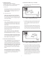
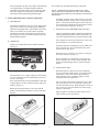
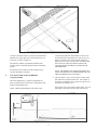
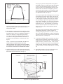
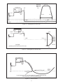
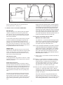
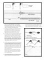
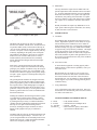
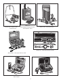
PROGRESSI VE
ELECTRONICS, INC.
May 1998
325 S. El Dorado, Mesa Arizona 85202
1-800-528-8224
Troubleshooting and Maintaining
Electrically Controlled
Zone Irrigation Systems
Issue 20
CONTENTS
1.
Troubleshooting at the Controller ................................Page 2
(Using Volt Ohmmeter)
2. Troubleshooting............................................................Page 3
(Using the Model 24)
3. Activating Solenoids ....................................................Page 3
(Model 24)
4. Identifying Wires.........................................................Page 3
(Models 77A & 200EP)
5. Locating the Path of Buried Wires...............................Page 4
(Models 501 & 508S)
6. Inductive Coupler .........................................................Page 4
7. Using the Inductive Antenna........................................Page 5
(Model 501)
8. Locating Wire Nicks or Breaks....................................Page 6
(Model 2003)
9. Locating Solenoid Valves, Wire Breaks
and Large Nicks (Model 521) ......................................Page 9
10. Model 528 Wire and Valve Locator ...........................Page 12
11. General Hints .............................................................Page 14
Figure 11
Figure 12
Figure 13
Figure 14
Figure 15
Figure 16
Figure 17
Figure 18
Figure 19
Figure 20
Figure 21
Figure 22
Figure 23
Figure 24
Figure 25
Figure 26
Figure 27
Figure 28
Figure 29
Figure 30
NECESSARY TEST EQUIPMENT
FIGURE INDEX
Figure 1
Figure 2
Figure 3
Figure 4
Figure 5
Figure 6
Figure 7
Figure 8
Figure 9
Figure 10
Flow Chart (Full Page) ......................................Page 2
Sending Tone From Clock.................................Page 3
Sending Tone From Valve .................................Page 3
Identifying Single Conductor ............................Page 4
Locating the Path of Buried Wires ...................Page 4
Determining Depth With 501 ............................Page 4
Determining Depth & Path With 508S .............Page 4
The Inductive Antenna ......................................Page 5
Placement of Antenna........................................Page 5
Placement of Antenna for Longer Distances.....Page 5
Searching for Underground “Utilities” .............Page 6
Pulser Transmitter Set-Up .................................Page 6
Pulser Receiver Set-up ......................................Page 7
Ground Return Fields ........................................Page 7
Nulling Receiver First Time ..............................Page 8
Nulling Receiver Second Time..........................Page 8
False Reversals ..................................................Page 8
Probing Path to Find Fault ................................Page 9
Four Quadrant Kick to Center.........................Page 10
521 Transmitter Set Up ...................................Page 10
Locating Wire Path With 521 ..........................Page 10
Locating End of Broken Wire .........................Page 10
Locating Wire Nick .........................................Page 11
Determining Depth ..........................................Page 11
Locating Solenoid Valves ................................Page 12
Tracking Path with 528 ...................................Page 12
Locating Broken Wires....................................Page 13
Measuring Depth .............................................Page 13
Locating Solenoids ..........................................Page 13
Examples of Hot Spots....................................Page 14
1.
2.
3.
4.
5.
6.
7.
Model 24 Solenoid Activator and System Tester
Model 77A Tone Generator
Model 200EP Inductive Amplifier
Model 501 & 508S Cable Locators
Model 2003 Short To Earth Ground Locator
Model 521 Broken Wire 7 Solenoid Valve Locator
Model 528 Compact Wire & Solenoid Valve Locator
All of the above equipment is manufactured by Progressive
Electronics, Inc., Mesa, Arizona, and are pictured on page 15.
PROGRESSIVE ELECTRONICS
TROUBLE SHOOTING AND MAINTAINING ELECTRICALLY CONTROLLED
ZONE IRRIGATIONS SYSTEMS
1. TROUBLE SHOOTING AT THE CONTROLLER.
Automated irrigation systems are a dream when working properly. When a problem develops it can be a long
and tedious process to solve.
Learn to use your ohmmeter and at least one of your
problems is over. the other half is easy, too, if you have
the proper locating equipment.
The FLOW CHART is designed to take you completely
through a malfunctioning irrigation system and insure
your ability to identify and solve your problems, step
by step. (See Fig. 1)
With the aid of a volt ohmeter, this section should help
you determine what conditions exist so you can begin
to solve your problems.
FLOW CHART LEGEND
嘷 Circles indicate start or end.
〫 Diamond shape boxes indicate decision points.
□ Square boxes indicate things to do.
START
MASTER
VALVE ON
TURN
CLOCK ON
ALL OK
END
SEQUENCE
CLOCK
NOTHING
WORKS
TURN
CLOCK OFF
SOME GOOD
SOME BAD
LIST
BAD ONES
CHECK
FUSE
SELECT
FIRST BAD
BAD
GOOD
MEASURE
110V TO
CLOCK
MEASURE
CLOCK VOLTAGE
STATION TO
COMMON
NO
VOLTAGE
VOLTAGE OK
REPLACE
FUSE
NO VOLTAGAE
VOLTAGE OK
MEASURE
VOLTAGE TO
EARTH
GROUND
REPAIR
CLOCK
TURN
CLOCK OFF
RX1
RX1K
NO VOLTAGE
VOLTAGE
ON HOT
CHECK
110V AT
SOURCE
CHECK RESISTANCE
FROM NEUTRAL
TO EARATH GROUND
DISCONNECT
STATION &
COMMON
CHECK
RESISTANCE
FROM
STATION TO
COMMON
SELECT
STATION
#1
MORE THAN
180 ⍀
CHECK
RESISTANCE FROM
STATION TO GROUND
& COMMON TO
GROUND
STATION
LESS THAN
COMMON
CHECK RESISTANCE
FROM HOT & NEUTRAL
TO EARTAH GROUND
FIX
FIND
FAULT
FIND
VALVE
COMMON
LESS THAN
STATION
SOURCE OK
DISCONNECT
HOT & NEUTRAL
FIND FAULT
IN NEUTRAL
LESS THAN
180 ⍀
FIX
BLEED
VALVE
VALVE GOOD
VALVE BAD
FIND
FAULT
FIX
VALVE
NO VOLTAGE
REPLACE
SOLENOID
FIND
FAULT
FIX
Figure 1 – Flow Chart
2
TURN
CLOCK ON
FIX
SEQUENCE
CLOCK
FUSE
BLOWN
TURN
CLOCK OFF
REPLACE
FUSE
OK
END
2. TROUBLE SHOOTING
(Using the Model 24. Picture on page 15.)
The Station Master, Model 24, is a portable hand held irrigation system diagnostic tester and solenoid activator.
4. IDENTIFYING WIRES (Using 77A & 200EP)
How to identify a single conductor from the bundle of
the same colored wires.
A. Battery Test
Place the toggle switch in the “ON” position and connect
the leads together. If the LED glows, the batteries are suitable for use. (Batteries must supply at least 12.5V for
“good” indication)
B. Current Test (At Clock)
With the clock on and turned to the station under test,
place the Station Master in the “OFF” position and connect one lead to the station wire and the other to the common. If the LED glows, the clock is supplying enough current to operate solenoids.
Figure 2 – Sending Tone From Clock
C. Wire Test (At Valve)
A. To do this, first you have to send a tone down the subject wire using the 77HP Tracer. You can start at the
clock or send the tone back towards the clock. (See
Figs. 2 & 3)
NOTE: TO INSURE PROPER CONNECTION, PLACE
THE WIRE FAR ENOUGH INTO THE JAW OF THE
ALLIGATOR CLIP SO THE PIN WILL PIERCE THE
INSULATION.
The red lead of the 77HP is clipped to the wire being
identified and the black lead to an earth ground using a
screwdriver. Move the switch to the tone position and
return to the location where identification will be made.
Turn the clock on and cycle to the station under test. Go
out to the valve and with the Station Master in the “OFF”
position, hook the leads to the station and common wires
and note condition of LED.
NOTE: MAKE SURE THAT ALL OTHER EQUIPMENT IS DISCONNECTED FROM THE CIRCUIT
BEFORE PERFORMING ANY TEST. (i.e., 521, 2003)
If the LED glows, this indicates the station and common
wires are in “good” condition. (The clock must be supplying 24 VOLTS with less than 180 OHMS of loop resistance to indicate a “good” condition.)
3. ACTIVATING SOLENOIDS (Model 24)
NOTE: THE PRESENCE OF AC VOLTAGES IN THE
“ON” POSITION WILL DAMAGE THE MODEL 24.
To activate a solenoid at the valve, make sure the clock is
off and connect the leads to the station and common wires,
then turn the Station Master “ON”. This will activate the
solenoid. The Model 24 must be turned “OFF” then “ON”
to activate a second solenoid. The Station Master will
hold a solenoid open for over three (3) hours with fresh
batteries.
Figure 3 – Sending Tone From Valve
B. Now you have to find the one wire that is carrying the
tone. Pick up the 200EP Line Aid and depress the large
black button on the side and touch the tip of the 200EP
to the insulation of the wires in the ditch. A light tone
may be heard from all the wires but the tone will be
tremendously louder on the subject wire. If there is a
loud tone on several wires, keep turning the volume
down on the 200EP and re-touch the wires. If a single
wire cannot be determined, earth ground all other wires
at the clock. The wire under test will be the only one
with tone. (See Fig. 4)
The only field maintenance required by the Model 24 is
the periodic replacement of the two (2) 9v alkaline batteries. (Eveready #522 are recommended.) Remove the four
(4) screws on the back, snap in fresh batteries and
reassemble.
3
Figure 4 – Identifying Single Conductor
5. LOCATING THE PATH OF BURIED WIRES (Using 501
and 508S)
THESE UNITS ARE NOT DESIGNED TO LOCATE
SOLENOIDS OR GROUND FAULTS.
Models 501 (The Tracker) and 508S (The Wire Finder) are
most widely used for locating the path and depth of the
buried wires in a sprinkler irrigation system. Both units
transmit the same high radio frequency; however, the 501
is capable of distances up to 4,000 feet and depths to 7
feet. The 508S is a lower powered version, good for distances around 1,000 feet and depths to 3 feet.
Figure 6 – Determining Depth With 501
A. The transmitters of these units have two black leads, one
of which is connected directly to the wire end or metallic
pipe and the other to earth ground with a screwdriver. Turn
the transmitters on and you are ready to track the wires.
The 501 receiver works on a “peak” signal when directly
over the path and the 508S “nulls” (absence of signal)
over the path. Walk completely around the transmitters
(fifteen to twenty feet away) with the receiver until the
direction of the path is determined, then simply follow the
signal. (See Fig. 5)
B. To track the path of a “system,” remove only the station
wire and the common wire from the clock. Connect one
transmitter lead to the station wire and the other to the
common. Signal will travel all through the system going
down the station wires, through the coil in the solenoid,
then back out the common. This application enables you to
“blueprint” a system and create your own “as built.”
Figure 7 – Determining Depth & Path With 508S
C. Depth of the wire can be determined with both the 501
and 508S using the 45 degree triangulation method. (See
Fig. 6 & 7)
6. INDUCTIVE COUPLER
A. DESCRIPTION
The Inductive Coupler is designed to induce a tracking
tone into a subject cable or wire without establishing metallic contact. (See page 15)
The Inductive Coupler is constructed of plastic and iron,
measures 4.5"x10x7.5", weighs 1 pound and can accomodate up to a 3" cable.
B. OPERATION
Clamp the Inductive Coupler around the insulation of the
buried cable to be tracked. Connect both transmitter leads to
Figure 5 – Locating the Path of Buried Wires (501)
4
Proceed down the cable path following the peak signal.
the two terminals on the face of the coupler. Turn transmitter
on to approximately a #5 output setting and radius the
immediate area with the tracker receiver to determine path.
The power output may be increased for greater distance.
Proceed down cable path following the peak signal.
NOTE: AS PROGRESS IS MADE DOWN THE CABLE
PATH, GRADUAL INCREASES IN THE GAIN CONTROL
OF THE RECEIVER WILL BE NECESSARY TO MAINTAIN
RECEPTION.
7. USING THE INDUCTIVE ANTENNA (Model 501)
Eventually, reception will be effectively lost, even at the
maximum transmitter setting. Retrieve the antenna and
place it at the point where the signal was last effectively
received. Resume tracking the line and repeat the relocation of the Inductive Antenna as necessary.
A. DESCRIPTION
The Inductive Antenna (See Fig. 8) is used to apply a tracking tone into a cable, wire or metallic pipe by radiating a
signal from the ground surface. This method is used when
there is no accessible way to make a direct connection.
The Inductive Antenna or transmitter loop is fitted inside
the carrying case of the 501 System and is powered by the
Model 500HP transmitter.
C. SEARCHING FOR UNDERGROUND UTILITIES
The activated 500CAA Inductive Antenna will radiate the
tracking signal through surface and the target utility will
receive the signal and effectively transmit it down its path.
One craftsperson will carry the antenna case close to the
ground and move in a specified direction.
B. OPERATION
Plug the two antenna leads into the 500HP transmitter.
(See Fig. 8)
Another craftsperson will hold the receiver (500R) a distance of at least 20 ft. away and simultaneously move
parallel with the first person.
When the receiver is directly over a utility, a strong signal will be detected. (See Fig. 11)
Keep in mind that even though this is the easiest and
most convenient way to locate, caution should be used
because the radiated signal may be induced into other
utilities.
D. APPLICATION TIPS
Remember that any conductive line in the immediate
area can collect the radiated signal. In locations such as
trailer parks or other areas with congested facilities,
minor reductions in the transmitter output level may
eliminate unnecessary signal bleed.
Figure 8 - The Inductive Amplifier
Turn transmitter to a # 7 output setting, place the transmitter in its compartment with the leads facing to the rear of
the case. (See Fig. 9)
Place activated antenna on the ground parallel to and within approximately one foot to either side of the utility to be
tracked. (See Fig. 9)
The very nature of the Inductive Antenna may be a problem to the operator if he is not prepared to pick up the
tone from the antenna itself. Begin using the receiver 20
feet or more away from the antenna to avoid receiving
signal on a direct basis.
Radius the area approximately 20 feet away from the
Inductive Antenna with the Tracker receiver to determine
the path.
Figure 9 applies to situations involving shorter runs or
work relatively close to the antenna.
Figure 9 – Placement of Antenna
Figure 10 - Placement of Antenna For Longer Distances
5
Figure 11 - Searching for Underground “Utilities”
To achieve maximum distance, orient the activated antenna
parallel to the suspect path, only set the Tracker II case up
on its back, as shown in Figure 10.
LOCATE THE PATH OF THE WIRES. This has to be
pre-determined by using Models 501, 508S, 528 or 521.
(Refer to Sections 5 & 6) Once the path is flagged or
marked, you are ready to use the Pulser. DO NOT CONNECT TO LIVE CIRCUITS ABOVE 240VAC OR
TOUCH THE RED AND BLACK LEADS OF THE
TRANSMITTER.
The Inductive Antenna is permanently installed and is
weather sealed. No attempt should be made to field repair
the unit.
Provisions have been made to retrofit existing carrying
case with the Inductive Antenna.
8.
NOTE: THE MODEL 2003 PRODUCES HIGH VOLTAGES. DISCONNECT ALL WIRES FROM THE CONTROLLER WHEN FAULT LOCATING.
LOCATING WIRE NICKS OR BREAKS
(Using Model 2003)
A. The most effective way to use the Pulser is to first isolate
both ends of the suspected faulted wire. For example, if
the subject wire happens to be a station wire, take it loose
from the clock and at the valve.
The Pulser, Model 2003, is capable of pinpointing all
shorts to ground in direct buried wires, ranging from clean
breaks to small pinhole leaks.
If the suspect wire is the common, again isolate. Let’s say
that stations 1 through 6 work fine and 7 and 8 do not.
NOTE: THE PULSER, MODEL 2003, WILL NOT
Figure 12 - Pulser Transmitter Set-Up
6
Now, begin to probe the earth parallel to the predetermined path of the wire working away from the transmitter. Every time the transmitter pulses, a kick will be
observed on the receiver indicating the direction of the
fault. The kick will decrease in strength as you move
down the path and sometimes it will completely disappear. Signal will reappear and increase in strength as
you approach the fault. (See Fig. 14)
You can speed up the fault locating process by covering
more distance between the points where you insert the
A-Frame into the ground. These distances are dictated
by the strength or weakness of the kicks. For example,
you are probing the path and at approximately 30 feet
away from the transmitter, you start to lose the intensity
of the “kicks” even after you have turned the receiver
knob all the way up. This means that you can pick up
and move down the path in 30-foot increments. If the
distance is 100 feet, move down and probe the path
every 100 feet.
Figure 13 - Pulser Receiver Set-Up
Isolate the common at valve 6 and 7, then start or set up at
valve 6 and work the path between them; then do the
same between 7 and 8.
This process of the ground return fields produced by an
earth gradient fault locator is shown in Figure 14.
Continue probing the path until a “reversal”, or “black
kick” occurs. When this happens, we know the fault lies
somewhere between the last ground reference point and
where you are now. (See Fig. 15)
B. The transmitter set-up begins with connecting the red lead
to the faulted wire and the black lead to earth ground with
the stake provided. (See Fig. 12) When the transmitter is
turned on, it discharges a voltage burst approximately
every three seconds. This voltage travels out the suspect
wire, bleeds to earth ground at the fault and returns in a
straight line to the ground stake or reference point. (See
Fig. 14)
D. To narrow this distance down, you slowly move the AFrame back toward the last ground reference point or
in the direction of the “black kick”. Continue this until
another reversal or “red kick” occurs. Now we know
the fault is somewhere between the two ground probes
of the A-Frame. When the A-Frame evenly straddles
the fault, the meter will null. Mark this spot. (See Fig.
16)
NOTE: IF THE CLOCK IS INDOORS, THE BLACK
LEAD MUST BE CONNECTED TO ITS OWN
GROUND STAKE AND AT THE LOCATION WHERE
THE WIRES EXIT THE BUILDING. DO NOT USE AN
ELECTRICAL GROUND OR A WATER PIPE INSIDE.
E. Repeat this procedure, only now at right angles to the
path and mark where the second null occurs.
C. Attach the Pulser receiver to the A-Frame and connect the
cord set. Insure that the words “Front” on the receiver and
the A-Frame are on the same side. (See Fig. 13)
Figure 14 - Ground Return Fields
7
Figure 15 - Nulling Receiver First Time
Figure 16 - Nulling Receiver Second Time
Figure 17 - False Reversals
8
Figure 18 - Probing Path to Find Fault
Your two marks should form an X and the fault lies
directly below the X. (See Fig. 17)
Progress outward in small increments. Continue doing this
watching the meter and anticipating the reversal. When the
reversal happens, bring the inward leg in small increments
until the meter nulls. Gather the slack and attach it to the
outside leg of the A-frame. Bring the A-frame to the ground
steak on the other side of the paved area and insert the lead
leg into the ground near the ground stake. Hold on to the
wire, which is doubled now, and walk with them back on to
the slab. The fault lies below the end of the loop.
F. SPECIAL FAULT LOCATING PROBLEMS:
False Reversals
False Reversals may occur when the path of the faulted
conductor serpentines and crosses the “ground return
line” (See Fig. 18) The “ground return line” is the path
the voltage is seeking on its way back from the ground
fault to the ground stake.
9. LOCATING SOLENOID VALVES, WIRE
BREAKS AND LARGE NICKS
To insure that an actual fault is located, always orient the
A-Frame in quadrants surrounding the suspected fault.
(See Fig. 19) If an actual fault is located, all four (4)
quadrants will result in the meter kicking to the center. If
not, you may have encountered a “false reversal” and the
actual fault is further down the line and in the direction of
the quadrant that did not kick to the center.
The Model 521 is a universal trouble shooting and maintenance tool for electrically controlled sprinkler irrigation
systems and is capable of locating the wire path, depth,
wire breaks, large nicks and solenoid valves.
NOTE: THE TRANSMITTER PRODUCES HIGH VOLTAGE.
TURN TRANSMITTER OFF BEFORE HANDLING
THE OUTPUT LEADS. DISCONNECT ALL WIRES
FROM THE CONTROLLER WHEN FAULT LOCATING. TURN THE SELECTION SWITCH TO THE
BATTERY TEST POSITION. THE METER SHOULD
READ BETWEEN 8 AND 10.
Multiple Faults
Multiple faults will cause the receiver to reverse at each
fault, the most solid fault will produce the strongest signal
or kick. The best policy is to repair the first fault you
locate, then reconnect the Pulser and locate the next one
until you have cleared all the trouble.
A. Before we start, you must make sure that the transmitter is
set up properly.
High Resistance Faults
A very high resistance may produce a weak kick. To help
make this fault easier to locate, simply turn the sensitivity
all the way clockwise.
IMPORTANT: To insure that the 521 transmitter is producing
optimum signal, connect the red and black leads together
and turn the unit on. Turn the selector to position # 5.
The meter needle should rise to at least a 10 reading. If
not, change batteries and try this test again. If the meter
still reads below a 10, return the unit for repair.
Faults Under Paved Areas
We have determined that a fault lies somewhere under a
paved area. On one side of this area, the kicks are outward,
and on the other side, they are in the opposite direction. If
it is impossible to excavate both sides and pull a new conductor through existing conduit, the following procedure
can pinpoint the exact location from on top of the paved
area.
CAUTION: DO NOT CONNECT TRANSMITTER TO ANY
ACTIVE A.C. CIRCUITS OVER 120VAC. With the
transmitter off, connect the red lead to the wire to be located and the black lead to a good earth ground with the stake
provided. (See Fig 20)
Get a piece of wire at least twice as long as the area to be
traversed. Strip both ends and attach one end to a ground
stake inserted on one side of the paved area. Attach the
other end to the inside leg of the A-frame and insert the outside leg into the ground on the opposite side of the paved
area.
If the clock is indoors, the earth ground stake MUST be
grounded at the point where the wires exit the building. It
might require running a length of wire to the outside. Do not
use a common ground inside (i.e. electrical or water pipe).
9
Figure 19 - Four Quadrant Kick To Center
Now turn the transmitter on and start rotating the selector
switch clockwise. As you will notice, once you leave the
“battery test” position and go to # 1, the meter needle will
fall off to near zero. As you increase the output, the needle will rise slightly with each advancement. Stop when
the meter reads between 4 and 8. The transmitter is now
set for maximum efficiency for this job. If a reading of 4 is
not obtainable, you may not have enough of a ground fault
to locate the wire.
Plug the headset into the receiver, turn it on and point the
antenna or probe end at the transmitter. A pulsing tone
should be heard through the headset and an indication
should register on the receiver meter.
NOTE: HIGH PITCHED TONES FROM THE HEADSET
MAY OCCUR IF THE HEADSET CORD GETS TOO
CLOSE TO THE RECEIVER ANTENNA OR THE
RECEIVER BATTERY IS LOW.
B. With the probe pointed toward the ground, walk completely around the transmitter location. An absence of tone or
null will be detected directly over the path of the wire.
Movement to either side will cause the volume of tone signal intensity to increase. Follow the null to determine the
wire path. (See Fig. 21) When attempting to find breaks
and nicks, you should DECREASE THE SENSITIVITY
OF THE RECEIVER when pointing it off to either side of
the null. You will be able to notice the change in signal
intensity immediately. DO NOT ALLOW THE METER
TO PEG OR GO ABOVE 10. This will greatly help in the
fault locating process.
NOTE: THE WIRE MUST HAVE A PATH TO GROUND TO
BE SUCCESSFULLY LOCATED. THESE PATHS
Figure 20 - 521 Transmitter Set Up
Figure 22 - Locating End of Broken Wire
Figure 21 - Locating Wire Path With 521
10
Figure 23 - Locating Wire Nick
EXIST IN A GREAT MAJORITY OF ALL DIRECT
BURIED WIRES DUE TO INSULATION IMPERFECTIONS, NICKS AND BAD SPLICES. IF NOT, CREATE
ONE BY GROUNDING THE REMOTE END.
Move the receiver away from the path maintaining the 45
degree tip until a null is detected. Mark this spot. The
depth is the distance between the two marks. (See Fig. 24)
C. The end of a cut or broken wire can be located by following the path until the null disappears and gives way to a
hot spot. Beyond the hot spot, no null can be detected.
Back up until the null is detected and this will be the
approximate end of the broken wire. (See Fig. 22)
D. Larger nicks in the wire can be located in almost the same
way as locating opens. Follow the null and strong signal
along the sides of the wire until the signal becomes very
weak along the sides of the null. This will occur within a
relatively short distance. The transmitted signal bleeds to
ground at the nick then wants to return back to the ground
stake along the outside of the wire itself. The majority of
signal will stop at the nick indicated by the low receiver
reading just beyond the nick. (See Fig. 23)
E. To more accurately define the location of an open or larger
nick (ground fault) position the receiver tip on the ground
near the point where the last strong signal was detected
along the side of the path. The receiver tip should be pointing at the ground and be approximately six inches to either
side from the null. Because you are so much closer to the
path, the sensitivity knob must be adjusted down until the
meter reads just below 10.
While maintaining the six-inch distance from the null,
move the receiver down the line paying close attention to
the meter reading. Once you pass the open or nick, the
meter will fall off rapidly.
F. To determine the depth of the wire, first mark the ground
directly over the path. Turn the receiver side-ways to the
path, tip it 45 degrees or level the bubble on the face.
Figure 24 - Determining Depth
11
10.
MODEL 528 WIRE AND VALVE LOCATOR
The Model 528 Wire and Valve Locator is designed to aid
in the troubleshooting and service of electronically controlled zone irrigation systems. The unit’s primary features include the ability to locate path, find breaks and
determine the depth of direct buried control wiring.
Additionally, the Model 528 can be used to pinpoint the
exact location of buried solenoid valves or identify a specific valve in a multiple valve location.
CAUTION: THE MODEL 528 PRODUCES A HIGH
VOLTAGE SIGNAL. DO NOT HANDLE LEADS
WHEN THE TRANSMITTER IS TURNED ON!
A. Battery Test
It is recommended that the battery condition of both the
transmitter and receiver be checked prior to any locating
function. To test the transmitter battery, connect (short)
the red and black leads to each other and turn on transmitter by lifting the plunger switch. A bright flashing LED
indicates acceptable transmitter battery conditions. Next,
turn on the receiver to the half position and move the
antenna near the transmitter. A loud tone indicates acceptable receiver battery condition.
Figure 25 - Locating End of Broken Wire
G. Solenoid valves can easily be located provided all the
wires leading to them are intact and the solenoid itself is
still good.
B. Tracking the Path of Buried Wires
Isolating (disconnecting) the subject wire from other wires
normally produces the best results when tracking the path
of a wire.
LOCATING SOLENOID VALVES IS A 2-STEP PROCESS.
Step 1. Start at the clock by connecting the red transmitter lead
to the station wire leading to the subject valve and the
black lead to earth ground. Turn the transmitter on, adjust
the output to the highest level, assemble the receiver,
locate the path and start tracing the wire following the null.
The null will be present until you pass over a solenoid
valve, then the signal will become extremely strong. Mark
this spot. Check around this hot spot for a null leaving the
area. If the null continues, follow it and mark any additional “hot spots”. (See Fig. 25)
With the transmitter off, connect the red lead to the subject
wire and connect the black lead to earth ground using the
supplied grounding stake. Turn on the transmitter and note
the condition of the LED. A flashing LED indicates an
acceptable signal path has been established. Next, turn on
receiver and “sweep” a circle around the transmitter (stay at
least 5 feet away from unit) listening for the peak signal
intensity. With the antenna hanging perpendicular to the
ground, the audible signal will increase as you near the
wire then “null” (no signal) directly over the subject wire,
then a loud signal will be heard on the other side of the
wire. Swing the antenna over the suspected cable path following the nulls and mark the wire path. (See Figure 26)
If only one “hot spot” or valve is located, this will be the
valve in question.
Step 2. If more then one “hot spot” is found, mark them
and return to the transmitter and turn it off. Lift the black
lead form the ground stake and connect it to the common
wire. Turn the transmitter on and set selector switch to
highest reading and return it to the first hot spot with the
receiver. Touch the tip of the receiver antenna to the
ground in the center of the first hot spot and set the sensitivity knob to make it read near mid-scale. Now go to the
second spot and without touching the sensitivity knob,
check strength of the signal at each hot spot and determine
which, out of all of them, is the strongest signal. This is
the valve for the station wire you are connected to.
NOTE: FEATURED IN THE 521’S RECEIVER IS A PHOTO
CELL LOCATED IN THE METER. IT WILL TURN “OFF”
AUTOMATICALLY IN DARKNESS, INSURING NO BATTERY DRAIN IF LEFT ON WHEN RETURNED TO THE
CASE. DAYLIGHT USE ONLY.
Figure 26 - Tracking Path with 528
12
C. Locating Broken Wires
E. Locating Buried Solenoid Valves
To locate the end of a broken wire, use the same method
for tracking the path of a buried wire. The signal will
become stronger as the antenna approaches the break, then
quickly decrease to no signal at all as the antenna passes
beyond the break.
To more accurately identify the location of the break, hold
the antenna perpendicular to the ground and the cable
(approximately 6” left or right of the wire) and move the
antenna down the wire path over the suspected area of the
break. Signal intensity will diminish significantly as the
antenna passes the break. (See Figure 27)
The Model 528 provides a fast and accurate method of locating
buried solenoid valves or identifying a specific valve within a
bank of valves. This process requires adherence to the following
2-step procedure:
Step 1. Disconnect the common (ground) and station wires in
question from the clock. Connect the red lead to the subject station wire and the black lead to earth ground using the included
ground stake. Turn on a transmitter and check for a flashing LED
indicating a good signal path. Track the path of the buried wire
using the null method listening for and marking distinct “hot
spots” of signal intensity. Often times at a hot spot, the signal
intensity will be strong enough that a complete null may not
occur. In this situation, a stronger signal will be present on both
sides of the wire path with a weak signal over-riding the null.
Step 2. Turn the transmitter off and remove the black lead
from the ground stake and connect it to the common (ground)
wire of the subject solenoid valve. Return to the previously
marked hot spots and investigate each of them. Select the area
with the strongest signal intensity. This area is most likely the
specific valve attached to the red lead of the transmitter.
Confirmation of the valve can be achieved using a 2-axis null
method. Mark the approximate area of the hot spot. Next,
hold the antenna low and parallel to the ground while passing it
back and forth over the hot spot as shown in Figure 29. A distinct null will be detected intersecting your movements as right
angles. Mark this line of null points then repeat the procedure
to create a second line of null points at approximately 90
degrees to the first line. The intersection of the two lines
Figure 27 - Locating Broken Wires
D. Determining the Depth of Buried Wires
To determine the depth of a buried wire, first track the path
of the conductor using the null method and mark the null
location where a depth measurement is required. Next, hold
the antenna at a 45 degree angle to the ground and move (at
a right angle) away from the cable path until a second null
point is located. Mark the second null point and measure
the distance between the marks. The distance between
marks is the approximate depth of the wire. (See Figure 28)
Figure 29 - Locating Solenoids
(X-nulls) confirms the subject valve has been identified and
pinpoints the exact location of the buried valve.
NOTE: THE 2-AXIS NULL (X-NULLS) WILL ONLY
OCCUR ON THE SPECIFIC VALVE (STATION WIRE)
ATTACHED TO THE TRANSMITTER. THE EXCEPTION
TO THIS RULE WOULD BE THE UNLIKELY PRESENCE
OF A NEATLY COILED SLACK LOOP ON THE CIRCUIT
CREATED IN STEP 2. ANY OTHER HOT SPOT WILL
PRODUCE ONLY A SINGLE LINE OF NULL POINTS OR
NONE AT ALL.
Figure 28 - Measuring Depth
13
G. Maintenance
The only maintenance required on the Model 528 is the
periodic replacement of the transmitter and receiver batteries. To replace transmitter batteries, remove four Phillips
head screws from battery cover, replace with eight (8) Dcell batteries (note polarity), then reassemble. To replace
the receiver batteries, remove four slotted screws, separate
case, replace one (1) standard 9 volt batter, then reassemble.
Should your Model 528 require any additional service or
repair, please contact Progressive Electronics, Inc. directly
at (800) 528-8224 or (602) 966-2931.
11.
GENERAL HINTS
Figure 30 - Examples of Hot Spots
A. Conditions
F. Helpful Hints
Soil conditions play an important role in the success of a
locator. High radio frequencies (501 & 508S) are not governed as much by these conditions as are low audio frequency locators (528 & 521). Low frequency locators perform best in damp, clay-type soil (Model 2003 included)
as opposed to dry, sandy and rocky conditions. This might
clear up the questions of why the units work better one
day and differently on others. In other words, a high resistance fault (small hole or path to earth ground the wire) in
dry soil may be located much more easily if the conditions
were dense and damp.
The Model 528 will increase in value as a technician
becomes more familiar with the device. Because the locator provides audible results, a technician will develop an
“ear” for certain conditions as experience with the locator
increases. Hot spots, or areas of signal intensity, will vary
in intensity depending on the quality of the circuit path
and condition of the batteries. Hot spots are created by
broken wires, low resistance faults (worn or severely
nicked insulation), buried solenoid valves, bad/faulty
splices, sharp direction changes and buried slack loops.
(See Figure 30)
B. Your Own Test Site
Work slowly. Passing the antenna over the cable path
every few inches will prevent a technician from missing
(passing by) any number of situations. Keep the swing of
the antenna down to a short (12 to 24”) pendulum. This
will allow the technician to progress more quickly along a
wire path. Again, experience with the product will speed
future operations.
To insure that the equipment is working properly and to
further acclimate yourself to their capabilities, create your
own mini-test site.
Bare both ends of a 30" length of 12 or 14 gauge wire.
Stick the far end into the earth, stretch it out and connect
the various locators to the near end. Follow the instructions and this way, you can actually see what is happening
when it happens. If you still are having problems, please
contact the factory.
The ground path will determine the strength of the transmitter signal. The far end of the subject conductor must
permit a signal path to ground. If the transmitter LED in
the on position shows a dim flashing light or no lights at
all, test the batteries then assure the far end of the wire is
grounded. It may be necessary to wet the ground or manufacture a ground contact if no circuit is established with
the normal connection.
C. Using a Multimeter
Use a volt ohmmeter (Rx1 Scale) at the clock. Power off
and common wire disconnected, probe across the common
wire and to each station wire.
Isolating the conductor (disconnecting it from the system)
is essential when working with any locating or testing
equipment. This practice will serve two functions. First,
by isolating the subject wire(s), a technician eliminates
variables from the troubleshooting application and assures
that only one wire path or station is being located.
Second, by isolating the subject conductor, the risk of
damage to the equipment or injury to technician is
reduced.
ANTICIPATED RESULTS FROM READINGS:
0 - 5 ohms
8 - 10 ohms
10 - 180 ohms
180 ohms to ⬁
Automatic Shut-off will occur on both the transmitter and
receiver units after approximately 1 1/2 hours of use. If
you are using the Model 528 for extended periods of time
and the units “time out”, simply turn both the transmitter
and receiver completely off then on again.
14
=
=
=
=
Fully shorted Solenoid
Shorted Solenoid or Multiple Valves
Normal — All OK
Bad connections, Splices, Nicked Wire
Open Solenoid or Broken Wire.
Model 2003 - Short to Earth
Ground Locator
Model 24 Station Master Solenoid Activator
and Diagnostic Tester
Model 701K - Tone & Probe Kit
Model 501 - Cable, Pipe & Wire Locator
Model 508S - Cable, Pipe & Wire Locator
Model 528 - Compact Broken Wire &
Valve Locator
Model 521 - Broken Wire & Solenoid Valve Locator
15