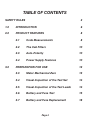
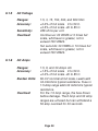
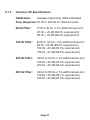
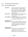
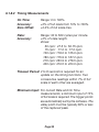
1
TRIPLETT
2000
Series
Type 3
Railroad Test Sets
Instruction Manual
Model 2000
Model 2001
Model 2002
Model 2003
84-873
7/07
SAFETY RULES
Warning
This Tester has been designed with your safety in mind. However,
no design can completely protect against incorrect use. Electrical
circuits can be dangerous and/or lethal when lack of caution or poor
safety practices are used.
Read the Manual
Read this Instruction Manual carefully and completely. Voltages and
currents within the capability of this test equipment can be hazardous. Follow the instructions in this manual for every measurement.
Read and understand the general instructions before attempting to
use this tester. Do not exceed the limits of the tester.
Safety Check
Double check the switch setting and lead connections before making measurements. Are you following all of the instructions? Disconnect the tester or turn off the power before changing switch
positions. Do not connect to circuits with voltage present when
switch is in any ohms or current position. When replacing fuses, use
only specified type fuses and insert in correct fuse holder.
Page 2
Don't Touch
Don't touch exposed wiring, connections, or other "live" parts of an
electrical circuit. If in doubt, check the circuit first for voltage before
touching it. Turn off the power to a circuit before connecting test
probes to it. Be sure there is no voltage present before you touch
the circuit. Do not use cracked or broken test leads.
High Voltage Is Dangerous
Always start with the power off. Be sure there is no voltage present
before making connections to the circuit. Don't touch the tester, its
leads, or any part of the circuit while it is on. Before disconnecting
the tester, turn the circuit off and wait for the meter to return to
"zero".
Distribution Circuits Pack a Punch
In high energy circuits such as distribution transformers and bus
bars, dangerous arcs of explosive nature can occur if the circuit is
shorted. If the tester is connected across a high energy circuit when
set to a low resistance range, a current range, or any other low impedance range, the circuit is virtually shorted. Special equipment
designed for use with these circuits is available. Contact a qualified
person for assistance before attempting to make measurements on
any high energy circuit.
Safety Is No Accident
Note: Specifications subject to change without notice.
Page 3
TABLE OF CONTENTS
SAFETY RULES
2
1.0
INTRODUCTION
6
2.0
PRODUCT FEATURES
8
2.1
Code Measurements
8
2.2
The Cab Filters
10
2.3
Auto-Polarity
10
2.4
Power Supply Features
10
3.0
PREPARATION FOR USE
12
3.3
Meter Mechanical Zero
13
3.4
Visual Inspection of the Test Set
14
3.5
Visual Inspection of the Test Leads
14
3.6
Battery and Fuse Test
15
3.7
Battery and Fuse Replacement
18
Page 4
4.0
GENERAL OPERATION
20
5.0
OPERATION
22
5.1
Measuring AC and DC Voltage
22
5.2
Measuring DC milliAmps
24
5.3
Measuring DC and AC Amps
26
5.4
Measuring Resistance
28
5.5
Measuring Dry Contacts
32
5.6
Measuring DC Pulse Code Signals
33
6.0
SPECIFICATIONS
34
6.1
Electrical Specifications
34
6.2
Physical Specifications
43
7.0
ACCESSORIES, PARTS, AND SERVICE
44
8.0
LIMITED WARRANTY
48
Page 5
1.0
INTRODUCTION
1.1
Package Contents
The standard shipping package contains the following items:
Test Set
Test Leads
This Instruction Manual
Carrying Case with Strap
Spare Fuses
Two, 9V Alkaline Batteries
One, D-cell Alkaline Battery
1.2
Product Description
The Model 2000 Series of Railroad Test Sets are specialized VOM's
designed for measuring the signal parameters of railroad coding
equipment. They maintain compatibility with older technologies,
while at the same time, offering functions and features not found on
standard VOM's.
1.2.1
Easier to Use for Normal Operation
Fewer jacks, more ranges, and a logical layout of the front panel all
contribute to the Test Sets' ease of use. The use of a multi-turn
Ohms Adjust Control facilitates accurate resistance measurements.
Also, the measurement of relay contact on time requires no adjustments.
Page 6
1.2.2
Measurement of Code Parameters
The measurement of code parameters has been made simple and
accurate. No longer is it necessary to count pointer swings to measure code rate. On time can be measured on live signals as well as
relay contacts. Peak levels can be determined quickly and automatically. Adjustment to the code equipment peak level can also be
made without constantly readjusting the Test Set.
1.2.3
Expandable
Optional circuit boards may be installed to allow for the filtering of
60 Hz, 100 Hz, 200 Hz, or 250 Hz cab signals. The base unit may be
upgraded at any time to include these filters without loosing the
initial investment.
1.2.4
Four Models
The 2000 Series currently consists of four models. The base Model
2000 has all the features mentioned above with the exception of the
Cab Filters. The Model 2001 includes selectable 100 Hz and 250 Hz
Cab Filters. The Model 2002 includes selectable 100 Hz and 200 Hz
Cab Filters. The Model 2003 includes selectable 60 Hz and 100 Hz
Cab Filters.
1.2.5
Selectable DC Amps Polarity
The DC Amps function has selectable polarity. This is useful for measuring the transmit and receive currents in pulse coded track circuits.
Page 7
2.0
PRODUCT FEATURES
2.1
Code Measurements
Code parameters may be directly measured with the Test Set. These
code measurements are active in any AC or DC voltage or current
range, as well as the Dry Contact function. These functions are selected by placing the Code Function Switch in the desired position.
The Pointer will momentarily return to zero and then indicate the
appropriate reading. If the Range Switch or any other switches are
changed, then the measurement circuitry is automatically reset and
made ready for the new measurement.
2.1.1
Peak Hold
This function will capture and hold the peak level of the signal. If the
peak level of the signal is varying slightly, the Test Set will average
25 of these readings to give an average peak level. For DC functions, the polarity of the peak is also captured and displayed using
the NEG Indicator. For the Dry Contact Range, Peak Hold will capture and hold a momentary contact closure.
CAUTION: The 2000 Series Type 3 will continue to read out the
averaged value of the last captured measurements, even after the
signal has been removed. The value will continue to be read out
until a new signal is captured or the Test Set is reset by changing
the setting of the Code Function switch or the Range switch.
Page 8
2.1.2
Peak Follow
This function is similar to Peak Hold, except the peak measurement
will follow the peak level automatically, even if it is decreasing. This
permits easier adjustment of peak levels. No averaging is performed,
so if the peak level is varying, the Pointer will follow it.
WARNING: The 2000 Series Type 3 will continue to read out the
value of the last captured measurement, even after the signal has
been removed. The value will continue to be read out until a new
signal is captured or the Test Set is reset by changing the setting of
the Code Function switch or the Range switch.
2.1.3
Rate
This function directly measures the rate of the signal. The result is
displayed on the CODE RATE scale. Only after two readings are
taken and found to be close together, does the Pointer deflect. It
may require up to eight seconds for the reading to be updated if the
rate changes. This reduces the possibility that noise may cause a
false rate indication. Also, the peak signal level must be at least
10% of full scale for the measurement to be made. The rate of the
highest level signal of either polarity is displayed.
2.1.4
On Time
This mode is similar to the Rate function, except the percentage of
time that the signal is on is displayed. The on time is read using the
"%" scale. Nominal Code Rate is 50% duty cycle.
Page 9
2.2
The Cab Filter
If the Test Set has Cab Filters, then all AC functions may select one
frequency to be measured. This is invaluable when multiple cab
signals are being sent, as it negates the need to turn off one of the
cab signals to measure the other one. The Signal Select Switch is
simply placed in the position indicating the frequency to be measured. All functions behave the same, except that only the signal of
interest is measured.
2.3
Autopolarity
2.3.1
Auto-Polarity
For all DC functions, the Test Set works in the auto-polarity mode.
The highest level peak of either polarity and its timing parameters
will be measured. In this mode, the Pointer will always deflect upscale, with the NEG Indicator lighting for signals of negative polarity. The highest level peak of either polarity and its timing parameters will be measured.
2.4
Power Supply Features
2.4.1
The Sleep Feature
Since the Test Set relies on batteries for operation, a battery saving
feature has been incorporated to extend the battery life if accidentally left on. This is known as the Sleep mode. After approximately
five minutes of non-use (Pointer at less than 1% of scale and no
range switch changes) the Test Set will power down, reducing battery drain and extending battery life. This mode is indicated by the
Pointer deflecting down scale into the Sleep Zone. To reactivate the
Test Set, simply rotate the Range Switch. NOTE: DURING SLEEP,
THE TEST SET WILL NOT RESPOND TO ANY INPUT.
Page 10
2.4.2
Battery Monitor
To prevent operation of the Test Set with weak batteries, a battery
test is performed every time the Range Switch is changed. If the
batteries are low, the Pointer will deflect down scale into the Sleep
Zone. It will not respond to any input making measurements impossible. This feature prevents low batteries from providing false readings if they fall below a voltage at which the internal circuitry is designed to operate reliably. Note that even though the Pointer is in
the Sleep Zone, the Test Set is not in a low current mode. After
approximately five minutes, the Test Set will revert to the battery
saving Sleep mode.
2.4.3
Sleep Mode Disable
The Test Set contains a field changeable jumper located on the left
of the small circuit board on the bottom of the large main circuit
board. This is found by removing the four screws holding the RF
shield. This jumper, when in position 1-2, will enable the sleep mode.
To disable the sleep mode, move the jumper to the 2-3 position.
Page 11
3.0
PREPARATION FOR USE
3.1
Before using the Test Set, familiarize yourself with the
instrument and this manual. READ AND REVIEW THIS MANUAL
FREQUENTLY.
3.2
Each time the Test Set is used, check, and if necessary,
correct the mechanical zero of the meter. Refer to Section 3.3.
Inspect the Test Set for mechanical defects as described in Section
3.4. Also, inspect the test leads as described in Section 3.5. Finally,
perform the Battery and Fuse Test as described in Section 3.6. Only
after all tests have been passed should the Test Set be used. DO
NOT USE THE TEST SET IF ANY OF THESE TESTS FAIL.
Page 12
3.3
Meter Mechanical Zero
3.3.1
Place the Test Set on its back on a flat, horizontal surface.
Set the Range Switch to the OFF position.
3.3.2
Examine the position of the Pointer on the Dial. If it is exactly on the Zero Mark, then the meter is mechanically zeroed and
no adjustment is necessary.
3.3.3
If the Pointer is not exactly aligned with the Zero Mark,
then the mechanical zero of the meter needs adjustment. This is
done by using a small, flat blade screwdriver to adjust the Zero Adjust Screw. Slowly turn the Zero Adjust Screw clockwise until the
Pointer is approaching the Zero Mark from below zero. When the
Pointer is resting on the Zero Mark, reverse the Zero Adjust Screw
one eighth turn. This will disengage it and reduce the effect that
temperature, shock, and vibration will have on the mechanical zero
of the meter.
Page 13
3.4
Visual Inspection of the Test Set
Before use, inspect the Test Set for any conditions which would
make it unsafe. Check for missing or loose parts ( knobs, screws, or
insulators ). Check also for damage, such as cracks, chips and burn
marks. Make certain that the Test Set is free from oils, grease, dirt
and excessive moisture. IF ANY OF THESE CONDITIONS ARE
FOUND, DO NOT USE THE TEST SET.
3.5
Visual inspection of the Test Leads
Before use, inspect the test leads for worn or cut insulation. Check
also for deterioration of the insulation. Make certain that no wire is
exposed and that the jack insulators and alligator boots are not
cracked, broken, torn, or otherwise damaged. Check also for loose
or missing parts. IF THE TEST LEADS ARE IN ANY WAY DAMAGED OR DEGRADED, DO NOT USE THEM. THEY MUST BE
REPLACED. DO NOT USE TEST LEADS THAT HAVE BEEN ALTERED OR ARE NOT A FACTORY APPROVED REPLACEMENT.
Page 14
3.6
Battery and Fuse Test
Before using the Test Set, and frequently during use, the batteries
and fuses in the Test Set should be tested. Refer to Section 3.7 for
instructions on installing and/or replacing the batteries and fuses if
necessary.
3.6.1
9V Battery Test
Place the Test Set Range Switch in the OFF position. Depress and
hold the Push For Ohms Switch. The Pointer will deflect upscale
and the red NEG Indicator will light. If the Pointer fails to deflect into
the blue BATT OK scale, then both 9V batteries must be replaced.
Replace the batteries if necessary, then repeat this test. Proceed to
the Fuse Test (Section 3.6.2) only after successfully passing this test.
3.6.2
Fuse Test
The Test Set contains two fuses. Both must be tested and found
good for safe operation of the instrument.
Page 15
3.6.2.1 VOM Fuse Test
Place the Test Set Range Switch in the DRY CONTACT position.
Place the Code Function switch in the NORM position. Connect the
test leads to the instrument. The red lead is attached to the VOM
Jack and the black lead to the COM Jack. Short the leads, and the
Pointer must deflect to full scale. If it fails to do so, fuse F201 (1A/
250V 8AG) must be replaced. (Paragraph 3.7.3) Replace this fuse if
necessary, then repeat this test. Proceed to the 1.5 AMP Fuse Test
(Paragraph 3.6.2.2) only after successfully passing this test.
3.6.2.2 1.5 AMP Range Fuse Test
While the Test Set is still set as in Paragraph 3.6.2.1, move the black
test lead from the COM Jack to the 1.5 AMP Jack. Short the leads,
and the Pointer must deflect to full scale. If it fails to do so, fuse
F202 (10A/250V 3AB) must be replaced. (Paragraph 3.7.3) Replace this fuse if necessary, then repeat this test. Proceed to the Dcell Battery Test (Paragraph 3.6.3) only after successfully passing
this test. RETURN THE BLACK TEST LEAD TO THE COM JACK.
FOR ALL NORMAL USE AND OTHER TESTS, THE BLACK TEST
LEAD MUST BE CONNECTED TO THE COM JACK.
Page 16
3.6.3
D-cell Battery Test
Place the Test Set Range Switch in the Rx1 position. Short the test
leads together (they must be in the VOM and COM jacks). Depress
the Push For Ohms Switch and, using the Ohms Adjust Control,
attempt to set the Pointer to full scale deflection. If this is possible,
then the D-cell battery is good. If the Pointer cannot be set to full
scale, then the D-cell battery must be replaced. Replace this battery if necessary, then repeat this test. Only after successfully passing all of the preceding tests is the Test Set ready for use.
Page 17
3.7
Battery and Fuse Replacement
3.7.1
Case Back Removal
3.7.1.1 Disconnect any test leads connected to the Test Set and
place the Range Switch in the OFF position.
3.7.1.2 Remove the case back by turning the large thumb screw in
the center of the case back counter clockwise.
3.7.2
Battery Replacement
3.7.2.1 Remove the D-cell and two 9V alkaline batteries under the
white insulator if they are installed.
3.7.2.2 Install fresh batteries in the clips provided. The D-cell is
oriented with the positive to the small white dot on the meter back.
The 9V batteries can only be installed one way. They must both be
replaced at the same time.
3.7.2.3 Place the 9V batteries into the holders making sure that
the white insulator covers them.
Page 18
3.7.3
Fuse Replacement
3.7.3.1 Locate the two fuses on the Input Scaling Board (BD200).
3.7.3.2 Using a small, flat blade screwdriver, gently lift the installed
fuse from its clips. Be careful so as not to bend the fuse clips.
3.7.3.3 Install a new fuse of the proper type. See Section 7.4 for
the correct type. Be certain that the fuse is securely seated in the
fuse clips.
3.7.4
Case Back Installation
Re-install the case back being careful not to pinch any wires. Tighten
the thumb screw finger tight.
Page 19
4.0
GENERAL OPERATION
4.1
This section describes general operation of the Test Set.
When making measurements of any type, refer to this section. THE
MODEL 2000 SERIES RAILROAD TEST SETS ARE INTENDED
FOR USE ONLY BY PERSONNEL TRAINED IN THE PROPER
SAFETY PROCEDURES AND WHO CAN RECOGNIZE SHOCK
AND SAFETY HAZARDS. Always prepare the Test Set for use by
reading and following the Preparation for Use section of this manual.
(Section 3.0)
4.2
High Voltage Measurements
CAUTION: Always observe the following rules and procedures when
making measurements in high voltage circuits.
4.2.1
Turn the equipment or voltage source off before connecting the test leads. Make certain that no capacitors in the circuit being tested remain charged to a high voltage.
4.2.2
Set the Test Set to the appropriate AC or DC Voltage range.
If not known, start with the highest range switch position and then
lower the range switch for an appropriate reading.
Page 20
4.2.3
While holding the insulated boot covering the alligator clip,
touch the alligator clips to the circuit being tested. If no voltage is
present, connect the alligator clips to the points to be measured. If
a voltage is found, check the equipment to make certain that all
power is off and all capacitors are discharged.
4.2.4
Turn the equipment or voltage source on and take the required reading. DO NOT HANDLE OR TOUCH THE TEST SET,
TEST LEADS, OR ALLIGATOR CLIPS WHILE THE EQUIPMENT
IS TURNED ON.
4.2.5
Turn the power to the equipment off and allow the reading
to return to zero before disconnecting the test leads.
Page 21
5.0
OPERATION
5.1
Measuring AC and DC Voltage
5.1.1
Refer to Section 3.0, Preparation For Use, and Section 4.0,
General Operation, before attempting any measurements.
5.1.2
Select the desired AC or DC voltage range by rotating the
Range Switch to the desired range. If measuring AC voltage with a
Test Set with Cab Filters (SIGNAL SEL. switch will be marked CAB
FILTER), set the Signal Select Switch to the AP +/- (ALL PASS /
AUTO POLARITY) position to measure all AC voltage present. Damage can result if high voltages are present at other than the selected
frequency. If only the cab signals are of interest, then set the Signal
Select Switch to the appropriate frequency. The Test Set will measure only that signal. A Test Set without Cab Filters will measure all
AC voltage present, regardless of the setting of the Signal Select
Switch. In DC Volts, the position of the Signal Select Switch has no
effect but should be left in the AP +/- or +/- position to avoid misinterpretation.
5.1.3
Attach the test leads to the Test Set. The red lead is connected to the VOM Jack, and the black lead is connected to the
COM Jack.
5.1.4
Connect the test leads across the circuit to be measured.
5.1.5
Read the voltage on the appropriate scale as noted in the
table on the following page. If the NEG Indicator lights, then the
input voltage is reversed from the polarity of leads.
Page 22
Range
Switch
Leads
Red
Black
Read
Scale
Multiply
Divide / Direct
0.6 VDC
3 VDC
15 VDC
60 VDC
300 VDC
VOM
VOM
VOM
VOM
VOM
COM
COM
COM
COM
COM
0 - 60
0 - 300
0 - 15
0 - 60
0 - 300
Divide by 100.
Divide by 100.
Direct reading.
Direct reading.
Direct reading.
1.5 VAC
3 VAC
15 VAC
150 VAC
300 VAC
600 VAC
VOM
VOM
VOM
VOM
VOM
VOM
COM
COM
COM
COM
COM
COM
0 - 15
0 - 300
0 - 15
0 - 15
0 - 300
0 - 60
Divide by 10.
Divide by 100.
Direct reading.
Multiply by 10.
Direct reading.
Multiply by 10.
5.1.6
If code parameters are to be measured, select the desired
parameter using the Code Function Switch. Refer to Section 2.1 for
a description of these functions. Peak levels are measured using
the same scales as used in the NORM mode. Rate is read using the
black CODE RATE scale. On time is read using the black percentage
(%) scale. Code parameters may be read on any range provided
that the peak level is approximately ten percent of full scale.
5.1.7
Disconnect the test leads from the circuit under test and
return the Range Switch to the OFF position.
Page 23
5.2
Measuring DC milliAmps
5.2.1
Refer to Section 3.0, Preparation For Use, and Section 4.0,
General Operation, before attempting any measurements.
5.2.2
Select the desired DC mA range by rotating the Range
Switch to the desired position. Place the Code Function Switch in
the NORM position. The position of the Signal Select Switch has no
effect in this mode.
5.2.3
Attach the test leads to the Test Set. The red lead is connected to the VOM Jack, and the black lead is connected to the
COM Jack.
5.2.4
sured.
Connect the test leads in series with the circuit to be mea-
5.2.5
Read the current on the appropriate scale as noted in the
table on the following page. If the NEG Indicator lights, then the
input current is reversed from the polarity of leads.
Range
Switch
15 mADC
60 mADC
300 mADC
Leads
Red_
Black
Read
Scale
Multiply
Divide / Direct
VOM
VOM
VOM
0 - 15
0 - 60
0 - 300
Direct reading.
Direct reading.
Direct reading.
COM
COM
COM
Page 24
5.2.6
If code parameters are to be measured, select the desired
parameter using the Code Function Switch. Refer to Section 2.1 for
a description of these functions. Peak levels are measured using
the same scales as used in the NORM mode. Rate is read using the
black CODE RATE scale. On Time is read using the black percentage (%) scale. Code parameters may be read on any range provided
that the peak level is approximately ten percent of full scale.
5.2.7
Disconnect the test leads from the circuit under test and
return the Range Switch to the OFF position.
Page 25
5.3
Measuring DC and AC Amps
5.3.1
Refer to Section 3.0, Preparation For Use, and Section 4.0,
General Operation, before attempting any measurements.
5.3.2 Select the desired AC or DC Amps function by rotating the
Range Switch to the desired function.
If measuring AC Amps with a Test Set with Cab Filters, set the Signal Select Switch to AP +/- to measure all AC current present. If
only cab signals are of interest, then set the Signal Select switch to
the appropriate frequency. The Test Set will measure only that signal. If using a Test Set without Cab Filters, all AC current present
will be measured.
For DC Amps, if it is desired to measure transmit and receive currents, place the Signal Select switch in the AP +/- position (Test
Sets with Cab Filters) or the +/- (Test Sets without Cab Filters) position. The peak level and timing parameters of the highest amplitude
signal are now automatically measured.
To select a particular polarity (transmit or receive) to measure, simply change the Signal Select switch to the + or the -position. That
signal will be captured. If the signal is of the opposite polarity (e.g. a
positive signal when the switch is set to -) the pointer will deflect
down scale. On Test Sets with Cab Filters, the + and - positions of
the Signal Select switch are also labeled with the Cab frequencies
applicable to that Test Set.
5.3.3
Attach the test leads to the Test Set. The red lead is connected to the 1.5 Amp Jack to measure 1.5 Amps AC or DC. It is
connected to the 6 Amp Jack to measure 6 Amps AC or DC, and it
is connected to the 30 Amp Jack to measure 30 Amps AC or DC.
Page 26
WARNING: THE 6 AMP AND 30 AMP JACKS ARE UNFUSED.
USE EXTREME CAUTION! The black lead is connected to the COM
Jack.
5.3.4
sured.
Connect the test leads in series with the circuit to be mea-
5.3.5
Read the current on the appropriate scale as noted in the
table below. If the NEG Indicator lights, then the input current is
negative.
Range
Switch
Leads
Red
Black
Read
Scale
Multiply
Divide / Direct
DC Amps
DC Amps
DC Amps
1.5 A
6A
30 A
COM
COM
COM
0 - 15
0 - 60
0 - 300
Divide by 10.
Divide by 10.
Divide by 10.
AC Amps
AC Amps
AC Amps
1.5 A
6A
30 A
COM
COM
COM
0 - 15
0 - 60
0 - 300
Divide by 10.
Divide by 10.
Divide by 10.
5.3.6
If code parameters are to be measured, select the desired
parameter using the Code Function Switch. Refer to Section 2.1 for
a description of these functions. Peak levels are measured using
the same scales as used in the NORM mode. Rate is read using the
black CODE RATE scale. On Time is read using the black percentage (%) scale. Code parameters may be read on any range provided
that the peak level is approximately ten percent of full scale.
Page 27
5.3.7
Disconnect the test leads from the circuit under test and
return the Range Switch to the OFF position.
5.4
Measuring Resistance
5.4.1
Voltage Sensing Mode
Before measuring resistance, the circuit to be tested must be
checked for a voltage which is present as this may present a safety
hazard and/or give a false reading. This is facilitated through the
Ohmmeter's voltage sensing mode.
5.4.1.1 Refer to Section 3.0, Preparation For Use, and Section 4.0,
General Operation, before attempting any measurements.
5.4.1.2 Select the desired Ohms range by rotating the Range Switch
to the desired position. The position of the Code Function Switch
and the Signal Select Switch does not matter.
5.4.1.3 Attach the test leads to the Test Set. The red lead is connected to the VOM Jack, and the black lead is connected to the
COM Jack.
5.4.1.4 Zero the Ohmmeter by shorting the test leads together and
depressing and holding the Push For Ohms Switch. The Pointer will
deflect. Use the Ohms Adjust Control to set the Pointer on the Ohmmeter Zero Mark. If this is not possible, then the D-cell battery needs
replacement. Refer to Section 3.7. When zeroed, release the Push
For Ohms Switch.
Page 28
5.4.1.5 Connect the test leads across the circuit to be measured.
5.4.1.6 If the Pointer deflects, then there is a foreign voltage present
which would cause errors in the resistance measurement, if attempted. The approximate full scale voltage is 15 VDC, although
AC voltage will also be detected. The NEG Indicator will light if the
test leads are unconnected, or if connected and no voltage, or negative voltage is present. For both positive and negative inputs, as
well as AC, the pointer will deflect upscale.
5.4.1.7 If a foreign voltage is detected, disconnect the test leads
from the circuit under test and refer to Section 5.1 to determine the
exact nature of the foreign voltage so that it may be removed.
5.4.1.8 If no foreign voltage is present, then a resistance measurement can be made. Proceed to Section 5.4.2.
5.4.2
Resistance Measuring Mode - After determining that there
is no foreign voltage present, a resistance measurement may be
made by depressing and holding the Push For Ohms Switch.
Page 29
5.4.2.1 Press and hold the Push For Ohms Switch and read the
resistance on the red OHMS scale. The Ohmmeter must be properly zeroed. See Paragraph 5.4.1.4.
5.4.2.2 Read the resistance on the appropriate scale as noted in
the table below.
Range
Switch
Red
Rx1
R x 100
VOM
VOM
Leads
Black
COM
COM
Read Red Ohms Scale
Multiply / Direct
Direct reading.
Multiply by 100.
5.4.2.3 Disconnect the test leads from the circuit under test and
return the Range Switch to the OFF position.
Page 30
This page intentionally left blank.
Page 31
5.5
Measuring Dry Contacts
5.5.1
Refer to Section 3.0, Preparation For Use, and Section 4.0,
General Operation, before attempting any measurements.
5.5.2
Set the Code Function Switch to the NORM position. The
position of the Signal Select Switch does not matter.
5.5.3
Attach the test leads to the Test Set. The red lead is connected to the VOM Jack, and the black lead is connected to the
COM Jack.
5.5.4
Connect the test leads across the contacts to be measured.
5.5.5
The Pointer will be in one of two positions. If the contacts
are open, then the Pointer will rest on the left side of the dial by the
OHMS scale infinity mark. If the contacts are closed, then the Pointer
will deflect to full scale and rest on the Ohms Zero Mark. The Pointer
will thus follow contact closure. Note: The pointer does not indicate
resistance of the contacts.
5.5.6
If code timing parameters are to be measured, select the
desired parameter using the Code Function Switch. Refer to Section 2.1 for a description of these functions. Rate is read using the
black CODE RATE scale. On Time is read using the black percentage (%) scale.
5.5.7
The Peak Hold and Peak Follow functions behave differently in the Dry Contact range than the other ranges. In the Dry
Contact range, Peak Hold and Peak Follow both, will detect and
hold a momentary contact closure. When a momentary closure is
detected, the Pointer will deflect to full scale and remain there until
reset by changing the Code Function Switch or the Range Switch.
Page 32
There is no difference between Peak Hold and Peak Follow in the
Dry Contact range.
5.5.8
Disconnect the test leads from the circuit under test and
return the Range Switch to the OFF position.
5.6
Measuring DC Pulse Code Signals
5.6.1
Overview
The DC Amps function has selectable polarity. This is useful for
measuring the transmit and receive currents in pulse coded track
circuits. The selection of the polarity is made via the Signal Select
Switch. In any other DC function (DC Volts or DC mA) the position
of the Signal Select switch has no affect. The polarity of pulse coded
signals cannot be selected in the DC Volts or DC mA functions.
5.6.2
Selecting the Polarity
To measure transmit and receive currents, see Section 5.3 in the
Instruction Manual. Place the Signal Select switch in the +/- position (for Test Sets without Cab Filters) or in the AP +/- position (for
Test Sets with Cab Filters). The peak level and timing parameters of
the highest amplitude signal are now automatically measured. To
select a particular polarity (transmit or receive) to measure, simply
change the Signal Select switch to the + or the - position. That
signal will be captured. If the signal is of the opposite polarity (e.g.
a positive signal when the switch is set to -) the pointer will deflect
down scale. On Test Sets with Cab Filters, the + and - positions of
the Signal Select switch are also labeled with the Cab frequencies
applicable to that Test Set.
Page 33
6.0
SPECIFICATIONS
6.1
Electrical Specifications
6.1.1
DC Voltage
Ranges:
Accuracy:
Sensitivity:
Overload:
6.1.2
0.6, 3, 15, 60, and 300 VDC.
±1.5% of full scale 0 to 50 C.
±2.5% of full scale -40 to 85 C.
1000 ohms per volt.
Continuous: 20 VRMS or 5 times full
scale, whichever is greater, not to
exceed 600 VRMS.
Ten seconds: 30 VRMS or 10 times full
scale, whichever is greater, not to
exceed 700 VRMS.
DC milliAmps
Ranges:
Accuracy:
Burden Volts:
Overload:
15, 60, and 300 mADC.
±1.5% of full scale 0 to 50 C.
±2.0% of full scale -40 to 85 C.
60 mV nominal at full scale. Leads and
fuse add 250 milliohms typical resistance.
Fuse blows before damage.
Page 34
6.1.3
DC Amps
Ranges:
Accuracy:
Burden Volts:
Overload:
6.1.4
1.5, 6, and 30 Amps DC.
±1.5% of full scale 0 to 50 C.
±2.0% of full scale -40 to 85 C.
60 mV nominal at full scale. Leads add
34 milliohms typical resistance. Fuse in
1.5 Amp range adds 30 milliohms typical
resistance.
For the 1.5 Amp range, the fuse blows
before damage. The 6 Amp and 30 Amp
ranges are unfused but can withstand a
50 amp overload for 30 seconds.
Common DC Specifications
NMRR:
>60 dB at 25 Hz, Code Function switch
in NORM position.
>35 dB at 60 Hz and >60 dB at 96 Hz,
Code Function switch in PEAK or
TIMING position.
Polarity Detect: All DC functions indicate upscale. A red
NEG indicator lights for inputs of negative polarity. For zero input, the NEG
indicator is off.
Page 35
6.1.5
AC Voltage
Ranges:
Accuracy:
Sensitivity:
Overload:
6.1.6
1.5, 3, 15, 150, 300, and 600 VAC.
±3.0% of full scale 0 to 50 C.
±3.5% of full scale -40 to 85 C.
288 ohms per volt.
Continuous: 20 VRMS or 5 times full
scale, whichever is greater, not to
exceed 700 VRMS.
Ten seconds: 30 VRMS or 10 times full
scale, whichever is greater, not to
exceed 700 VRMS.
AC Amps
Ranges:
Accuracy:
Burden Volts:
Overload:
1.5, 6, and 30 Amps AC.
±1.5% of full scale 0 to 50 C.
±2.0% of full scale -40 to 85 C.
60 mV nominal at full scale. Leads add
34 milliohms typical resistance. Fuse in
1.5 Amp range adds 30 milliohms typical
resistance.
For the 1.5 Amp range, the fuse blows
before damage. The 6 Amp and 30 Amp
ranges are unfused but can withstand a
50 amp overload for 30 seconds.
Page 36
6.1.7
Common AC Specifications
Calibration:
Average responding, RMS calibrated.
Freq. Response: 25 Hz to 400 Hz for rated accuracy.
60 Hz Filter:
57 Hz to 63 Hz ±1.5% additional level error.
25 Hz > 40 dB (99.0% suppression)
96 Hz > 40 dB (99.0% suppression)
100 Hz Filter:
92 Hz to 100 Hz ±1.5% additional level error.
60 Hz >34 dB (98.0% suppression)
120 Hz >20 dB (90.0% suppression)
156 Hz >47 dB (99.6% suppression)
200 Hz Filter:
196 Hz to 204 Hz ±1.5% additional level error.
156 Hz >20 dB (90.0% suppression)
250 Hz >20 dB (90.0% suppression)
250 Hz Filter:
245 Hz to 255 Hz ±1.5% additional level error.
156 Hz >38 dB (98.7% suppression)
200 Hz >20 dB (90.0% suppression)
Page 37
6.1.8
Code Measurement Specifications
6.1.8.1 Peak Level Measurements
Peak Hold:
Pointer will deflect to the peak level of
the input signal. For repetitive peaks
within a ±4% level window, 25 samples
are averaged, then no further updates
occur unless the level exceeds the
captured peak.
Peak Follow:
Pointer will deflect to the peak level that
is at least 25% of the previously
displayed peak.
Level Stability: For a peak to be detected, the signal must
remain level stable within ±4.0% typically
for a period of 10 milliseconds.
AC Rejection for
DC Functions: AC signals greater than 60 Hz and up to
five times the level of the DC signal to be
measured will typically introduce less
than 3% additional error in the level
measurement.
DC Rejection for
AC Functions: DC signals up to five times the level of
the AC signal to be measured will
typically introduce less than 3%
additional error in the level measurement.
Page 38
6.1.8.2 Timing Measurements
On Time:
Accuracy:
Zero Offset:
Range: 0 to 100%.
±3% of full scale from 10% to 100%.
±3.0% of full scale max.
Rate:
Accuracy:
Range: 30 to 500 cycles per minute.
±3% of scale length.
Zones:
50 cpm: 47.5 to 50.75 cpm.
75 cpm: 71.0 to 77.0 cpm.
120 cpm: 118.0 to 125.0 cpm.
180 cpm: 175.9 to 187.2 cpm.
270 cpm: 263.9 to 276.5 cpm.
420 cpm: 410.5 to 423.0 cpm.
Timeout Period: 2 to 8 seconds is required for an
update on the timing functions. Two
consecutive readings within 7% of full
scale of each other are averaged.
Minimum Input: For correct Rate and On Time
measurements, a minimum input of 13%
of full scale is required. The trigger points
are automatically set by the software. The
valley point must be typically 60% or less
of the captured peak.
Page 39
6.1.9
Ohmmeter
6.1.9.1 Voltage Sense Mode
Range:
Accuracy:
Sensitivity:
Overload:
15 V DC auto-polarity or AC to 1 KHz
typical. NEG indicator is on for zero and
negative inputs.
±20% -40 to 85 C.
1000 ohms per volt.
Continuous: 50 VRMS.
Ten seconds: 120 VRMS.
6.1.9.2 Resistance Measurement Mode
Ranges:
Center Scale:
Accuracy:
Open Circuit
Voltage:
Test Current:
Overload:
R x 1 and R x 100.
5 and 500 ohms.
±2.0% of scale length ±0.5 ohms
0 to 50 C.
±3.0% of scale length ±0.5 ohms
-40 to 85 C.
1.0 to 1.8 VDC. The VOM jack is
negative with respect to the COM jack.
R x 1 range: 400 mA max.
R x 100 range: 3.6 mA max.
R x 1 range: fuse blows before damage.
R x 100 range: 35 VRMS continuous.
Page 40
6.1.10
Dry Contact Functions
Normal:
Pointer follows contact closure.
Open: zero ±3.0% of full scale.
Closed: full scale ±0.5%.
On Time:
Range: 0 to 100 %.
Accuracy:
±2% of full scale from 10% to 100%.
Zero offset: ±3.0% of full scale max.
Rate:
Range: 30 to 500 cycles per minute.
Accuracy:
±3% of scale length.
Peak Hold:
Pointer will deflect to full scale and
remain there with a 2.0 millisecond or
longer contact closure.
Allowable Contact
Resistance:
0 to 100 ohms.
Test Voltage:
7.5 to 15 VDC. The VOM jack is positive
with respect to the COM jack.
Test Current:
830 uA max.
Overload:
Continuous: 50 VRMS.
Ten seconds: 120 VRMS.
Page 41
6.1.11
Power Requirements
Batteries:
Two, 9 volt alkaline batteries (NEDA 1604)
One, 1.5 volt alkaline D-cell (NEDA 13F)
Expected Life: Normal operation: 320 hours.
Sleep mode:
2000 hours.
Cutoff Voltage: 10.5 volts minimum for both 9V batteries
in series.
The ohmmeter circuit is designed to
properly zero with a D-cell battery from
1.0 to 1.8 volts.
Sleep Timer:
Test set falls asleep after 3 to 7 minutes
with no meter deflection greater than 1%
of full scale typical.
6.1.12
Meter Movement
Full scale:
Balance:
Construction:
100 uA ±1%
±1.0% of full scale.
Taut band construction, shock mounted.
100 degree deflection, critically damped.
Mirrored. High strength magnet.
Page 42
6.2
Physical Specifications
Size:
Weight:
Moisture
Resistance:
Temperature:
Humidity:
5.0" wide x 6.5" high x 3.2" deep.
Approximately 2.75 pounds, 4.75 pounds
with case and leads.
Test Set is not damaged by exposure to
rain.
Operating and storage: -40 to 85 C.
0 - 95% non-condensing.
Note: Specifications subject to change without notice.
Page 43
7.0
ACCESSORIES, PARTS & SERVICE
7.1
Cleaning the Window
Other than battery and fuse replacement, cleaning the window is
the only service that can be performed by the user. This may be
done by using a soft cotton cloth dipped in a solution of household
detergent and water. Wipe the window and allow to dry without rubbing or polishing. This will help to maintain the anti-static properties
so that the pointer does not stick or become erratic. Clean both the
meter window and the protective window.
7.2
Calibration
A one year calibration interval is recommended. Refer to qualified
service personnel.
Page 44
7.3
Factory Service
WARNING - DO NOT ATTEMPT TO SERVICE THIS UNIT.
ANY ATTEMPT TO SERVICE BY AN UNQUALIFIED PERSON
MAY BE DANGEROUS AND/OR LETHAL AND WILL VOID
YOUR WARRANTY.
To order parts or obtain service, contact:
Service Center:
Jewell Instruments
850 Perimeter Road
Manchester, NH 03103
1-800-874-7538
Page 45
7.4
Parts and Accessories
The following parts and accessories are available. Contact the factory for the latest in accessories.
Description
Model 2000, no Cab Filters
with yellow padded carrying case
Model 2001, 100 / 250 Hz Cab Filters
with yellow padded carrying case
Model 2002, 100 / 200 Hz Cab Filters
with yellow padded carrying case
Model 2003, 60 / 100 Hz Cab Filters
with yellow padded carrying case
Page 46
Part Number
2010
2011
2012
2013
Parts and Accessories (continued)
Description
Part Number
Test Leads, 14 AWG
79-767
Nine volt alkaline battery
37-48
D-cell alkaline battery
37-24
Fuse, 1A/250V 8AG Instrument
3207-30
( Littelfuse 361001,Bussman AGX 1)
Fuse, 10A/250V 3AB Normal Blow, Ceramic 3207-21
( Littelfuse 314010, Bussman ABC 10 )
Protective Window with screws
13568
Padded carrying case, yellow nylon
10-3967
Shoulder strap
3206-74
Tester hold down strap with hooks
3206-77
for 2000 Series (2 required)
Tester hold down strap with Velcro
3206-76
for other testers
Case back assembly
10-3866
Knob, range switch
34-266
Knob, small
34-270
Seal nut for push button switch
27-213
Instruction Manual
84-873
Page 47
8.0
LIMITED WARRANTY
Triplett / Jewell Instruments warrants instruments and test equipment manufactured by it to be
free from defective material or workmanship and agrees to repair or replace such products
which, under normal use and service, disclose the defect to be the fault of our manufacturing,
with no charge within one year of the date of original purchase for parts and labor. If we are
unable to repair or replace the product, we will make a refund of the purchase price. Consult
the Instruction Manual for instructions regarding the proper use and servicing of instruments
and test equipment. Our obligation under this warranty is limited to repairing, replacing, or
making refund on any instrument or test equipment which proves to be defective within one
year from the date of original purchase.
This warranty does not apply to any of our products which have been repaired or altered by
unauthorized persons in any way so as, in our sole judgment, to injure their stability or reliability, or which have been subject to misuse, abuse, misapplication, negligence, accident or which
have had the serial numbers altered, defaced, or removed. Accessories, including batteries
and fuses, not of our manufacture used with this product are not covered by this warranty.
To register a claim under the provisions of this warranty, return the instrument or test equipment to Jewell Instruments, Manchester, NH 03103, transportation prepaid. Upon our inspection of the product, we will advise you as to the disposition of your claim.
ALL WARRANTIES IMPLIED BY LAW ARE HEREBY LIMITED TO A PERIOD OF ONE YEAR
AND THE PROVISIONS OF THE WARRANTY ARE EXPRESSLY IN LIEU OF ANY OTHER
WARRANTIES EXPRESSED OR IMPLIED.
The purchaser agrees to assume all liability for any damages and bodily injury which may result
from the use or misuse of the product by the purchaser, his employees, or others, and the
remedies provided for in this warranty are expressly in lieu of any other liability Triplett / Jewell
Instruments may have, including incidental or consequential damages.
Some states (USA ONLY) do not allow the exclusion or limitation of incidental or consequential
damages, so the above limitation or exclusion may not apply to you. No representative of
Triplett / Jewell Instruments or any other person is authorized to extend the liability of Triplett /
Jewell Instruments in connection with the sale of its products beyond the terms hereof.
Triplett / Jewell Instruments reserves the right to discontinue models at any time, or change
specifications, price or design, without notice and without incurring any obligation.
This warranty gives you specific legal rights, and you may have other rights which vary from
state to state.
Page 48