1
8QLQWHUUXSWLEOH3RZHU6XSSO\836
3ODQQLQJDQG,QVWDOODWLRQ*XLGH
SOLIDSTATE
CONTROLS, INC.
Solidstate Controls Incorporated
875 Dearborn Drive
Columbus, Ohio 43085
Tel : (614) 846-7500
Fax: (614) 885-3990
8QLQWHUUXSWLEOH 3RZHU 6XSSO\ 836
3ODQQLQJ DQG ,QVWDOODWLRQ *XLGH
3UHIDFH
Solidstate Controls, Inc., is pleased to furnish this Planning and Installation Guide to inform
you about the UPS equipment and assist you in its installation.
The planning for an installation of electrical equipment as critical to your company as an
uninterruptible power system (UPS) deserves, and in some localities requires, the
attention of a qualified engineer or qualified electrician. SCI is pleased to assist you or your
technical staff in any way and has prepared this manual as a technical aid. However,
nothing herein should be construed as a substitute for proper engineering of a specific
installation.
7DEOH 2I &RQWHQWV
Introduction
How to Size a UPS Load .......................................................... Pg. 4
Section I
Electrical Considerations........................................................... Pg. 7
Section II
Physical & Environmental Considerations.................................Pg. 15
Section III
Battery Selection ....................................................................... Pg. 19
Section IV
Battery Room Physical &
Environmental Considerations .................................................. Pg. 21
Section V
Start-Up Supervision ................................................................. Pg. 24
Section VI
Service and Training ................................................................. Pg. 25
Blank Page for Notes ................................................................ Pg. 27
PROPERTY OF SOLIDSTATE CONTROLS, INC.
7/98
+RZ 7R 6L]H 8SV /RDGV
Good data on power consumption is often hard to get for small loads such as personal computers.
Most equipment below, for example, 800 Watts, will be 120 VAC, single phase, 60 Hz. rated
(Sometimes with a dual rating for 50 Hz. And 240 VAC for overseas usage).
Usually, each component of the computer system will have a tag placed near the location the
power cord enters the device.
Underwriter’s Laboratory (UL) requires that at a minimum, the voltage, amperage, and frequency
be identified.
The arithmetic product of the voltage and the amperage, i.e., V x A, gives a result in Volt-Amperes
often stated simply, VA. The Volt-Ampere (VA) is a universally accepted measure of electrical
capacity for the UPS industry.
VA capacity simply states that a given device may draw so many amps (A) at a particular voltage
(V). This is often a worst case value.
Many computer manufacturers overstate their equipment capacities by 20% or so to insure that the user provides
adequate electrical service to the system.
The VA capacity tells us nothing about how efficiently the device utilizes the energy it receives. The
measure of actual electrical energy usage is the watt (W.).
Sometimes the device label will state a wattage value, and this is particularly true for small loads
below 800 watts. Many small UPS systems will have their capacity stated in watts rather than voltamperes.
The ratio of watts over VA, i.e., W + VA gives us a measure of power utilization called the power
factor (p.f.).
For example, a computer with a volt-ampere rating of 120 VA, and a wattage rating of 96 watts has
a power factor of 0.8.
96 watts = 0.8 p.f.
120 VA
A good rule of thumb is to assume a power factor of 0.8 if both the wattage and volt-ampere rating
are not known.
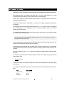
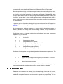
For example, an IBM desktop computer, the PS/2 Model 30 has the following label attached in the
back:
&38
%: 0RQLWRU
100-125 VAC
1.5 A
50/60 Hz.
100-125 VAC
.9 A
60 Hz.
PROPERTY OF SOLIDSTATE CONTROLS, INC.
7/1998
Notice that the wattage is not known nor is the power factor. Since in the U.S., 120 VAC is the
nominal value of input voltage, we can calculate the CPU’s volt-amperes (VA) directly:
IBM CPU – 120 V x 1.5 A = 180 VA
If we use our rule of thumb and assume a power factor of 0.8, then
180 VA x .8 = 144 Watts (W)
)RU WKRVH ZKR ORYH GHWDLOV The value difference between 180 VA and 144 W, 36 VA circulates as
unused power between the input power source and the computer.
So at this point we have two numbers 180 VA and 144 W, which one do we use? It depends on
how the UPS capacity is stated.
The SCI Powerbase UPS have their capacities stated in Volt amperes, but the DataShield UPS
have their capacities stated in watts. Use whichever number is appropriate to the UPS system
selected.
So far, we’ve only covered the CPU but the calculations for the monitor are similar:
IBM Monitor -
120 V x .9 A = 108 VA108
VA x .8 = 86 W
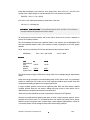
5HFDS
&38
IBM model 30
CPU
IBM B/W
Monitor
System Total
9$
:DWWV
180 VA
144 W
108 VA
288 VA
86 W
230 W
Thus we should be looking at a UPS with a V rating of 300 VA or a wattage rating of approximately
240 W.
Notice we’re being conservative in that the derating factor of 20% was not used. It is good design
practice to oversize the UPS to take care of those equipment additions such as tape drives and
modems that invariably get added to the computer system later.
In larger computer systems such as those supplied by IBM, DEC and Data General, detailed
computer printouts listing the volt ampere, wattage and peak current of each device can be
obtained from the computer manufacturer’s local sales office.
These print outs are essential for accurate, comprehensive sizing of the UPS system!
We have not mentioned three phase power which is found in larger computer systems, but the
principles are much the same; i.e., the individual device volt ampere (VA) ratings can be directly
added to produce a composite value. In these larger 3 phase systems (typically above 10,000 VA
or commonly written 10 KVA) wattage is almost never used as sizing measure.
PROPERTY OF SOLIDSTATE CONTROLS, INC.
7/1998
Three phase loads can be difficult to size, especially if there is a mixture of both single and three
phase devices in the system. Please call SCI for sizing assistance for those three phase
applications.
For the truly dedicated, Section III of the SCI UPS Installation and Planning Guide discusses three
phase applications.
PROPERTY OF SOLIDSTATE CONTROLS, INC.
7/1998
6HFWLRQ , (OHFWULFDO &RQVLGHUDWLRQV
$
836 6L]LQJ ² /RDG 6WXG\
The first step in sizing the UPS is to perform a thorough Load Study. When performing the Load
Study, it is important that all possible considerations be made for present needs and any planned
future expansion. All loads need to be analyzed with respect to various parameters, as described
below. The following is a discussion and examples of which loads need to be considered for a
computer room and how to use this information in sizing the UPS. The same procedure can be
used for load studies for any critical load:
1.
Computer Main Frame or CPU
2.
Printers
3.
Disk Drivers
4.
Plotters
5.
C.R.T. Terminals
6.
Any Other peripherals
7.
Emergency room lights, alarms, security, and all other loads which must be supported
when the computer is in operation.
8.
Any other DC loads
9.
Any projected expansion in the near future. Consider the planned addition of any
peripherals, CRTs, printers, etc., or new or additional computers. (It is more
economical to purchase one large UPS than two smaller ones to equal the same KVA
rating.)
Identify the voltage of each load, whether it is single phase, two phase, or three phase, and the
frequency.
In an effort to minimize the size of the UPS, and correspondingly the cost, one should consider which
devices, if any, need not be powered from the UPS. For example, if a computer room application
requires only time to properly power down the system, then you need not necessarily power your tape
drives. Also, suppose there are ten (10) terminals connected. Only one is necessary to power down. In
this way, one can minimize the initial cost by purchasing a smaller size UPS, which is likely to require
less floor space, less air conditioning, and less annual operating costs.
If some loads have different input voltages, it should be determined if they are convertible. For
example, the main frame may be able to accept either 208Y/120 VAC, three phase, or 240 VAC,
three phase inputs. If all other voltages are 120 V or 208Y/120 V, then 208Y/120 V should be
selected to power the main frame. This will eliminate the need for, and additional cost of, special
voltage transformers.
If any of the loads are three phase, then a three phase U PS is required.
PROPERTY OF SOLIDSTATE CONTROLS, INC.
7/1998
A single phase UPS with a 120 V output can supply only a 120 V load. However, a three phase
UPS with a 208Y/120 V output can supply either a 120 V single phase load, a 208 V two phase
load, a 208 three phase load, or a 208Y/120 V, three phase load.
In determining the size of a three phase UPS, single phases loads can be distributed between
each of the three phases. However, one large single phase load can be connected to only one
phase of a three phase UPS. This one load may well determine the size of the system, even
though the other loads may be very small.
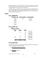
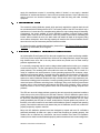
([DPSOH
67(3 ² ,GHQWLILHG /RDGV
SKDVH 9 ORDGV
SKDVH 9 ORDGV
SKDVH 9 ORDGV
75.0 amp
.5 amp
3.5 amp
7.0 amp
2.5 amp
5.0 amp
3.0 amp
1.5 amp
12.0 amp
5.0 amp
1.5 amp
67(3 ² %DODQFLQJ /RDGV
7KUHH 3KDVH 836 2XWSXW
$ SKDVH
% SKDVH
75.0
& SKDVH
5.0
2.5
1 phase loads
7.0
3.0
1 phase loads
3.5
1 phase loads
0.5
1 phase loads
1.5
1.5
2 phase loads
12.0
12.0
12.0
3 phase loads
1.5
1.5
1.5
3 phase loads
5.0
5.0
5.0
3 phase loads
93.5
32.5
29.5
67(3 ² 6HOHFW 836 6L]H
The actual minimum kVA required is calculated by multiplying the highest phase current times the
line-to-neutral voltage, times three, divided by 1000.
kVA = Amps (highest) x Voltage (line-to-neutral) x 3
`
1000
kVA = 93.5 x 120 x 3 = 33.66 kVA
100
PROPERTY OF SOLIDSTATE CONTROLS, INC.
7/1998
Selecting from our standard sizes, we find that we must supply a three phase, 40 kVA UPS which
has a 111 amp AC output per phase. One can see that “A” phase is 84% loaded, while “B” and “C”
phases are only 27% loaded, which means that there is substantial room for additional single
phase loads for future expansion – but only limited expansion room for three phase loads.
In the previous example, we have been looking at continuous full load currents. Any load which
has a significant inrush current must also be identified. In order to avoid an overload of the UPS, it
may be necessary to power-up the various loads sequentially. It may also mean that the way the
loads are balanced on a three phase UPS may need to change so that all the high inrush loads are
not on the same phase, if possible.
In the earlier example, if the 12 amp, three phase continuous load had an inrush of five times its
continuous rating (60 amp inrush), and if all other loads on “A” phase were “on” and we attempted to
start the load, a total load of 141.5 amps would be seen on “A” phase. This would cause an overload
and all loads would be transferred to the bypass source until the overload was cleared. If this is likely to
happen often, the consideration should be given to installing a large UPS. Note that SCI inverters are
designed to transfer to the bypass source upon an overload of 120-125% of full load.
As shown in the previous example, if the 5 and 7 amp loads on “B” phase both had inrushes of ten
times their rating and both could start at the same time, then an overload would occur. In this case,
consider moving on of the loads to “C” phase and perhaps an equal amount of load could be
moved from “C” phase to “B” phase.
There are usually many load considerations which must be looked at in sizing the UPS. Be sure that all
possibilities which might jeopardize the integrity of the continuous power have been considered.
%
836 6L]LQJ ² (VWLPDWLQJ IURP $YDLODEOH 'DWD
It may be necessary, for quotation purposes, to estimate the size of a UPS required for a particular
installation where time does not permit a detailed Load Study.
1. With all equipment operating, one method would be to use a clamp-on ammeter.
For a single phase, two-wire system, measure the hot leg. The kVA rating is calculated by
multiplying the measured current times the line voltage, divided by one thousand:
kVA = amps x voltage
1000
For a single phase, three-wire system (240/120), measure each hot leg. The kVA rating is the
highest current reading multiplied times the line-to-neutral voltage, multiplied times two, divided
by one thousand:
kVA = amps (highest) x voltage (line-to-neutral) x 2
1000
For three phase systems, measure all three hot legs. The kVA rating is calculated by
multiplying the highest current reading times the line-to-neutral voltage, times three, divided by
one thousand:
kVA = amps (highest) x voltage (line-to-neutral) x 3
1000
PROPERTY OF SOLIDSTATE CONTROLS, INC.
7/1998
If it is not possible to measure the actual current, it may be necessary to use one of the
following:
2. Obtain load profile from manufacturer for the individual loads. This will probably be necessary
for new installations. Add to this any lighting, alarms and security loads which are required.
3. In existing installations, check the capacity of the step-down isolation transformer supplying the
critical load or check the size of the distribution panel feeding those loads.
4. It may be necessary to contact the electrical contractor who installed the loads for load data.
In these last three cases, be sure to determine if there are any three phase loads. Even though
there is a three phase distribution panel or isolation transformer, there need not necessarily by any
three phase loads.
&
&UHVW )DFWRU &DSDELOLW\
Included in SCI UPS equipment is circuitry to allow the inverter to be compatible with loads
exhibiting a high crest factor. Today’s electronic computers and instrumentation equipment are
powered with high frequency switching power supplies, which draw non-linear current from the AC
source. Both SCI’s Ferroresonant and our power transistor PWM UPS systems have the designed
capability to supply these non-linear high crest factor loads. Without this capability the UPS will
either need to be over-sized or will experience unnecessary and potentially load damaging
nuisance transfers, while these high crest factor loads are operating.
For further information about non-linear loads and crest factor control, please refer to our technical
paper on the subject.
'
(OHFWULFDO 6HUYLFH IRU WKH 836
The Power source must be of sufficient capacity to handle the worst case demands for the UPS.
Primary power installations for the UPS is the responsibility of the customer. Future expansion
should be considered in determining power requirements. The customer is also responsible for the
installation of any input distribution panels, external battery disconnect switch as required by the
NEC and/or local codes, output distribution panels and wiring to the loads, unless such has been
bid by SCI as part of the customer package.
,QSXW 3RZHU &RQVLGHUDWLRQV DQG 'LVWULEXWLRQ
Consideration must be given to the input distribution panels for the UPS. What presently exists for
the load may not be too small, due to the losses in the UPS itself, the additional battery recharge
capability, and the overload capacity of the rectifier/charger. Some installations may have chosen a
larger rectifier/charger than that which would normally be supplied, due to some additional DC
loads or the customer’s desire to recharge the batteries at a faster rate. The maximum current
ratings provided should be consulted for this determination.
It might appear on the surface that this device is very inefficient, due to the rectifier/charger high
input current. This is not the case. Our rectifier/chargers are approximately 92-94% efficient.
The reason for the high input current is this. The output voltage regulation of the rectifier/charger is
accomplished by controlling the conduction interval of the thyristors. This is done by gating on the
thyristors at the proper time during each half cycle. This change of conduction interval allows the
PROPERTY OF SOLIDSTATE CONTROLS, INC.
7/1998
unit to maintain a constant output voltage with a varying input voltage. A longer conduction period
increases the DC output voltage and, conversely, a shorter period lowers the output voltage.
When the input voltage is high, the thyristors are gated on later during each half cycle. As a result,
in order to provide constant power, we will necessarily see a high current spike at this point which
we will refer to as form factor or crest factor. Consequently even though the kilowatts (KW), which
you pay for at the electrical meter, are what you might expect based upon 92-94% efficiency, this
“form factor,” or “crest factor,” causes a higher-than-normal peak current demand which must be
considered when selecting all upstream devices. (Note: Although not true power factor, this form
factor or crest factor, is many times expressed in those terms when discussing input requirements
for rectifier/chargers.)
In general, a good rule of thumb for estimating the input power requirements for a UPS system is to
use 2.5 times the output kVA rating for our Ferroresonant units and 2 times the output rating for our
PWM units.
All wiring, transformers, distribution breakers, etc., must be sized for the maximum currents, as
dictated by the NEC, even though, under normal operating conditions, the input current can be
expected to be much lower.
The following formula can be used to derive the rectifier/charger input power requirements
expressed in (VA) volt amperes.
CIP
=
Ve x Ar x C1
PF x EF
Ve
=
Charger equalize voltage
Ar
=
Charger rated output in amperes
C1
=
Charge current limit point (typically 1.2 to 1.25)
PF
=
Charger input power factor (typically 0.8)
EF
=
Charger efficiency (typically 92-94%)
CIP
=
Charger input power in (VA) volt amperes
The following formula can then be used to derive the rectifier/charger maximum input current. This
information is necessary in determining the UPS system input electrical service requirements.
Ac
=
CIP
V1 x 3
V1
=
3 phase AC input voltage at low line (typically nominal voltage –10 or –15%)
3
=
1.732
Ac
=
charger input current in amperes
Note: SCI can provide adjustable current limiting from 100% to 125% to aid in limiting the input
current requirements under conditions where maximum current limiting is not desirable.
(
%\SDVV 6RXUFH 6XSSO\
The bypass source input must be supplied with an input voltage and frequency which exactly
matches the output of the UPS. For example, if the UPS system output is 208Y/120 Vac, 60 Hertz,
then the bypass source input must be 208Y/120 Vac, 60 Hertz. If this matching voltage is not
available, an appropriate transformer must be installed to provide the proper voltage. SCI can
PROPERTY OF SOLIDSTATE CONTROLS, INC.
7/1998
supply this transformer mounted in a matching cabinet, if desired, or can supply a standard
transformer of another manufacturer in their own floor-mounted enclosure. Some customers may
wish to have their own electrical contractor supply and install this along with other necessary
equipment.
)
2XWSXW 'LVWULEXWLRQ 3DQHOV
The customer’s existing distribution panels, which previously supplied the computer loads, should
be re-evaluated before utilizing with the UPS. The inverter portion of the UPS can deliver only a
small amount of current above its nameplate ratting before the output voltage drops off drastically.
Consequently, the current available to trip the distribution breakers is severely limited. Ideally
breakers and/or fuses should be selected to clear the possible faults without overloading the
inverter. When overloads do occur, the static switch will transfer all loads to the bypass (utility)
source without interruption, where the large capacity will clear the fault. Since all transfers involve
some risk to the load, all unnecessary transfers should be avoided.
For further information regarding fault protection, please refer to “UPS Systems Distributor Network
Protection” by Laura Andrei, R & D Engineer.
*
&RQVLGHUDWLRQ 5HJDUGLQJ $& 'LVWULEXWLRQ IRU &RPSXWHU 5RRPV
An Uninterruptible Power System (UPS) is the most complete form of power conditioning available.
A UPS can provide complete protection from all forms of line voltage transients, surges and sages,
long duration brown outs, and is the only device which can provide total ‘no break’ back-up
protection against black outs.
It is commonly recognized that the various voltage related problems that trouble your computer
come from two sources. The first is atmospheric and accounts for approximately 20% of the total
power problems. The remaining 80% occurs within the users own building. This is a result of a
variety of conditions such as the presence of noise generating equipment like contactors, relays,
switches and fluorescent lighting, a general high power demand and the present of high inrush
loads like motors and other large inductors. Power problems also occur in the AC distribution
system as a result of distribution breakers with dirty contacts which result in high impedance, poor
connections including ground connections, incorrect grounding practices, improperly sized ground
neutral and power conductors and wiring errors. Surprisingly, wiring errors such as ground-neutral
reversals, poor or loose connections and improper wire sizes occur frequently, even in systems
which have been in use for a long period of time, and are unknowingly causing computer room
problems.
The UPS can correct all voltage problems caused by the various previously mentioned conditions
which exist up to the point of input to the UPS itself. However, if the AC distribution system which
exists between the output of the UPS and the various computer loads and peripherals has any of
the previously mentioned problems, voltage fluctuations may be re-introduced onto the clean
power generated by the UPS and, as a result, trouble with the computer system may continue. It is,
therefore, to the user’s benefit to be sure that this AC distribution system is designed and operating
properly. One would be cautioned not to assume that your AC distribution is error free, but that it be
properly analyzed by experts in that field.
Many such AC distribution systems have been designed by experts and have AC verifications
performed periodically (at least one a year) to assure that everything is operating properly, that
vibration has not loosened any connections, that circuit breakers have clean low impedance
contacts, that no loads have been added improperly and that breaker and wire current ratings have
PROPERTY OF SOLIDSTATE CONTROLS, INC.
7/1998
not been exceeded. If this is not being done, one would be advised to contact experts in that field
to aid you in performing this important periodic analysis.
One should also be aware that some computer peripherals, such as printers, are themselves noise
generators, and that proper filters should be used on these lines to prevent the transmission of this
noise from one device to another.
+
/RQJ 7HUP 3RZHU %DFN8S ² $& (QJLQH *HQHUDWRU
There are several options open to the customer to supply his critical load in the event of a long
term power outage. One is to provide a battery bank large enough to carry the load for the
prescribed length of time (see discussion of “Battery Sizing/Selection/Installation”). The other is to
utilize an engine generator which can supply the load almost indefinitely. If the customer has an
existing engine generator, he may wish to utilize it for back-up purposes. There are, however, a
number of points which should be understood before using an engine generator.
Even though an engine generator can be used for long-term back-up, batteries will still be needed.
In the event of a power outage, the engine generator will need to be started. If it has not been
started for some time, there may be some difficulty getting it started. Once started, it will need to be
brought up to speed before a steady voltage and frequency is established. During this period of
time, batteries will be needed as back-up to the UPS.
The engine generator probably cannot supply the computer directly. Although the engine generator
is adequate for loads not requiring precise power, such as lighting, this is obviously not adequate
for the computer. The nature of the engine generator is such that we can expect both voltage and
frequency to be constantly varying. The proper method of utilizing the engine generator for long
term back-up is to supply power to the Rectifier/Charger, thereby utilizing the UPS for voltage and
frequency regulations.
The engine generator manufacturer should also be made aware that the load will be of an SCRtype.
For estimating purpose, the requir3ed engine generator should be approximately 2.5 times the kVA
rating of the UPS. Please refer to SCI for specific data on specific equipment.
NOTE: SCI can provide logic to cut back current limit while operating from the generator to help
minimize the input requirements.
,
/RQJ 7HUP %DFN8S '& (QJLQH *HQHUDWRU
An alternative to the use of an AC engine generator is the use of a DC engine generator. In this
application the generator size can be smaller due to the fact that the only over-sizing required is
that necessary to overcome the inverter losses. Circuitry can be designed so the generator does
not attempt to recharge the battery. The generator size need only be from 1.3 to 1.5 times the kVA
rating of the inverter.
-
*URXQGLQJ
All SCI UPS enclosures are provided with grounding terminals located at the bottom. Equipment
should be grounded in accordance with the National Electrical Code and applicable local codes.
The electrical contractor will be aware of this necessity. A good current reference is FIPS PUB 94,
titled Guidelines on Electrical Power for ADP Installations, dated September 21, 1983. A copy of
this can be obtained by writing to the National Bureau of Standards.
PROPERTY OF SOLIDSTATE CONTROLS, INC.
7/1998
6HFWLRQ ,, 3K\VLFDO (QYLURQPHQWDO &RQVLGHUDWLRQV
6LWH VHOHFWLRQ DQG SODQQLQJ
The site selected for the UPS should be chosen with care since the type and amount of site
preparation required will vary according to the specific location and its relative location to the load.
$
/RFDWLQJ WKH 836
The relative location of the UPS to the load is important for several reasons. First, the greater the
distance between the UPS and the load, the longer will be the interconnection cables; the longer
the cables, the larger the wire will need to be in order to minimize the voltage drop in the wires.
This means greater expense. For example, a 20 kVA UPS with 120 VAC single phase output of
167 amps, if used with 2/0 gauge wire, ahs a voltage drop of 2.7 volts in 200 feet. The a 500MCM
cable, the voltage drop is only 0.7 volts. However, 500MCM wire is almost four times the size of the
2/0 gauge and proportionally more expensive. Second, and most important, is the fact that these
longer cables are more likely to pick up electrical noise from outside sources than are shorter
cables, simply because they are more likely to pass near noise generating equipment or other
noise carrying conductors. The elimination of electrical noise is one benefit of the UPS. It is
important to keep these cable lengths as short as possible and removed from the proximity of other
cables or noise generating equipment such as motors, switches, etc. If long cable runs are
unavoidable, greater care should be exercised in cable routing and sizing.
%
)ORRU 6SDFH 5HTXLUHPHQWV
The Inverter and Rectifier/Charger
It is important that adequate floor space be provided for the UPS electrical equipment. Check the
dimensional information on the appropriate data sheets for the floor space requirements. The UPS
equipment can be mounted with the back against a wall. Side access is not specifically required;
however, if side and rear access can be maintained, it may be helpful should service become
necessary. A clear area in front of the unit of at least five (5) feet should be maintained for service
personnel.
&
9HQWLODWLRQ &OHDUDQFH
In order to provide for adequate ventilation, the UPS should be installed in a room which has a
least 12 inches of clearance over the unit. The area above the UPS should be clear of any
obstruction which would impede air flow. Since cooling air enters through a grill at the bottom front
of the equipment, this area must also be kept clear of any obstructions.
'
)ORRU /RDGLQJ
The Inverter and Rectifier/Charger
Some of the larger UPS systems are relatively heavy. Care should be taken to assure that the floor
loading requirements are not exceeded. Reference can be made to the appropriate literature for
dimensions and weights. Floor loading can be expected to vary from 90 lbs. Per square foot on
smaller units to over 300 lbs. per square foot for our very large units. One should plan accordingly.
PROPERTY OF SOLIDSTATE CONTROLS, INC.
7/98
(
(TXLSPHQW 0RXQWLQJ 5HTXLUHPHQWV
The Inverter and Rectifier/Charger
This equipment is designed to set on any floor which is adequate to handle the loading. No bolting
to the floor is required, although some units have provision for bolting should the customer wish to
do so.
)
,QYHUWHU DQG 5HFWLILHU&KDUJHU 5RRP 5HTXLUHPHQWV
Room Temperature
All SCI Ferroresonant UPS systems are designed to operate at full load in an ambient temperature
of 0-40°C (32-104°F); 0-95% relative humidity; to altitudes of 5,500 feet (over 5,500 feet, consult
the factory). All SCI Powerbase (PWM) UPS systems to altitudes of 4,920 feet. However, as with
all electronic equipment, operating over a prolonged period of time at elevated temperatures may
be detrimental to the extended life of the equipment. In all probability we would expect the normal
temperature range to be between 70-80°F.
Some installations may require that equipment be designed to operate at 50°C (122°F) for periods
of time when normal cooling or ventilation has failed. SCI can design equipment to meet this
parameter where it is determined to be necessary.
High temperatures do have a negative effect on virtually all electronic components. For maximum
service life, plan the equipment room so that normal operating temperatures are between 65-90°F.
Appendix A shows actual worst case heat dissipation for our standard equipment which will aid you
in determining ventilation and air conditioning needs.
Since products do change frequently, you may contact SCI to verify current heat dissipation data.
Cleanliness
The equipment room should be relatively free of dust and dirt and other airborne contaminates as
heavy layers of dust will reduce the cooling efficiency of the electronic components.
Humidity and Condensation
It is important that the room low temperature control be adjusted to maintain the room temperature
above the dew point in order to prevent condensation of moisture on the electrical equipment.
*
8QORDGLQJ DQG 5RXWH ,QVSHFWLRQ
Unloading Facilities
Before the UPS equipment arrives at the installation site, a number of checks need to be made of
the facility. Specific equipment size will determine the importance of each of the following items.
First, check if the site has an adequate loading dock or an unloading area that is accessible to the
trucker. If unloading facilities are not adequate, one might consider unloading at some other
location which has proper facilities; perhaps a nearby business that is willing to cooperate, and
using a smaller truck to deliver equipment to the site, or using the services of a professional moving
company.
PROPERTY OF SOLIDSTATE CONTROLS, INC.
7/1998
Moving Equipment
At the unloading area, a forklift may be neede3d to remove the equipment from the truck. The
forklift capacity should be checked to be sure it is adequate to handle the weight of the equipment.
This information is available from the data sheets.
Note that the date sheets give total weight. If the outline drawing shows two equally sized cabinets,
the weight should be divided with approximately 60% in one cabinet and 40% in the other. If the
outline drawings show one larger and one smaller cabinet, the weight should be divided with
approximately 75% in the larger and 25% in the single smaller cabinet.
Route Inspection
Determine how the equipment will be moved from the unloading area to the installation room and
examine the passageway through the building to determine if there is adequate clearance to move
the largest and heaviest package. Remember, add to the height the lift truck, dolly, or other device
that will be used to move the equipment. Especially check doorways or places where the
equipment must go around a corner for proper clearance. If an elevator is going to be used, be
sure the lift capacity and size is capable of handling the largest and heaviest package. If a lift truck,
moving dollies, etc., are not available, these should be rented or otherwise secured and be
available when the equipment arrives.
+
)LUH DQG 6DIHW\ 3UHFDXWLRQV
In most cases, building fire and safety codes establish the degree of protection required for
installation of electrical equipment and batteries. These should be followed for the installation of
UPS systems.
Caution should be used to assure that the UPS is removed from areas in which flammable or
explosive materials are kept or manufactured.
Personnel should be instructed in emergency shut down procedures.
Electrical equipment can pose certain hazards to equipment maintenance personnel.
ONLY QUALIFIED PERSONNEL SHOULD BE ALLOWED
TO PERFORM MAINTENANCE ON THE EQUIPMENT.
,
6HFXULW\
Security of the UPS room or location is as important as security of your computer room or other
limited access area. There is a potential for damage to the equipment as a result of ignorance,
carelessness, or vandalism. In addition, an inexperienced operator could cause a loss of power to
your critical load by improperly manipulating the various controls on the UPS. Consequently, one
may wish to limit access to the UPS area and monitor entry through your comprehensive alarm
system.
-
6WRUDJH RI 6XSSOLHV
SCI recommends that the customer purchase and keep on hand replacement spare parts for the
electrical equipment. See Section VI of this manual. These parts should be stored in a clean, dry
PROPERTY OF SOLIDSTATE CONTROLS, INC.
7/1998
location which is subject to the same temperature variations as allowed for the Inverter and
Rectifier/Charger, i.e., 32° to 104°F.
.
9LEUDWLRQ
Standard UPS equipment is built to withstand mild, intermittent building vibration. However, the
equipment should not be considered to be seismic or earthquake proof.
It is impossible to predict a designed vibration tolerance for conditions that might be encountered in
various installations. If this is a concern, it should be discussed with a SCI factory engineer. SCI
has vast experience in designing and qualifying seismic equipment.
/
1XFOHDU &ODVV ( 4XDOLILHG (TXLSPHQW
SCI has a comprehensive program to provide Nuclear Class 1E equipment. All such equipment is
custom manufactured to the specific requirements of that particular location. For detailed
information please contact SCI.
PROPERTY OF SOLIDSTATE CONTROLS, INC.
7/1998
6HFWLRQ ,,, %DWWHU\ 6HOHFWLRQ
All SCI UPS Systems are designed to operate from virtually any commercially available battery
bank which exhibits the proper voltage range and current capacity to power that particular UPS.
Choosing the proper battery for the application then becomes one of examining these various
parameters and choosing the one most suitable for the particular application. The following is an
analysis of various battery types and methods for sizing these batteries utilizing the battery
manufacturer’s data.
These batteries fall into two general types: Stationary and sealed.
Stationary batteries are those which require ventilation due to the fact that they are designed to
release gases into the atmosphere including hydrogen when they are charging. Consequently,
these batteries also require routine maintenance such as periodic watering, specific gravity, and
voltage checks. In general, these batteries are longer-lived than sealed batteries.
Sealed batteries are those which are essentially sealed and release only small amounts of gas
under high internal pressure as a safety precaution. This would probably be a result of severe
overcharging. Normally, the hydrogen and oxygen gases generated as a result of battery charging,
recombine within the battery as water. No watering is necessary or possible.
The following batteries are examples of types normally used for UPS back up.
/HDG &DOFLXP ² 6WDWLRQDU\ %DWWHULHV
This type offers the best cost versus service reliability for stationary batteries available for UPS
installations. These batteries typically carry a 20-year warranty and have a 20-25 year life
expectancy when used under float conditions. Hydrogen generation is low compared to lead
antimony batteries and when maintained at a float voltage of 2.25 volts/cell, do not require
routine equalization. Maintenance consists of watering, terminal cleaning, and checking
electrolyte specific gravity at six-month intervals. Equalization is necessary only upon initial
energization.
/HDG $QWLPRQ\ ² 6WDWLRQDU\ %DWWHULHV
These batteries generally are equal in size and capacity to the lead calcium batteries. Usually
they are warranted for 15-20 years, with a life expectancy of 15-22 years. These batteries are
normally better suited for applications where they are cycled rather than in full float application.
Hydrogen generation is considerably greater than lead calcium batteries and maintenance is
required more frequently, including periodic (monthly) equalization, and weekly watering
checks with additions as necessary.
1LFNHO &DGPLXP ² 6WDWLRQDU\ %DWWHULHV
NICAD batteries are the most expensive of the stationary types discussed, costing
approximately two to three times calcium batteries. Although it requires 92 cells of nickel
cadmium to equal 60 cells of lead calcium, they still have an advantage in being smaller in size
and weight for a given capacity. They also have excellent low temperature and high
temperature properties and have an exceptionally long service life even at high temperatures.
Service life expectancy under normal conditions is approximately 25 years or more.
PROPERTY OF SOLIDSTATE CONTROLS, INC.
7/1998
6HDOHG 0DLQWHQDQFH )UHH %DWWHULHV
As previously discussed, sealed batteries are those which, due to special construction, do not
normally vent gas into the atmosphere, and because they are sealed, require no routine water
additions. Because they do not gas, they are well suited for installation into an office area or
computer room environment where special ventilation would be difficult or impractical to
provide. These two advantages present cost savings which should be considered when
evaluating your battery requirements. Sealed batteries lend themselves well to cabinet
mountings, and as a result can be attractively packaged for installation in an office or computer
room along with the UPS system. One can also recognize sealed batteries by the use of
names such as Gel Cell, Absorbed Electrolyte, Starved Electrolyte, or Suspended Electrolyte.
Sealed batteries are maintenance free only in the sense they require no electrolyte
checks or water addition. It is important that the battery terminal connections be inspected and re-torqued
periodically to maintain a sound connection.
$ ZRUG RI FDXWLRQ
Life expectancy and manufacturer’s warranties vary from 1 year to 20 years with a corresponding
variation in price. As an average, a 10-year sealed battery on an open rack will be priced
approximately equal to the lead calcium 20 year wet battery.
PROPERTY OF SOLIDSTATE CONTROLS, INC.
7/1998
6HFWLRQ ,9 %DWWHU\ 5RRP 3K\VLFDO $QG (QYLURQPHQWDO &RQVLGHUDWLRQ
$
%DWWHU\ 5RRP 7HPSHUDWXUH
Since battery operation results from a chemical reaction, temperature plays a significant role in
performance and life. A standard temperature of 77°F (25°C) is used to rate the batteries. It is
recommended that the battery room temperature be maintained as close as possible to this
temperature (72-80°F would be acceptable).
Care should be taken not to locate batteries where they will be in direct sunlight or near a register which
might subject one or more cells to high or low temperatures. The temperature differential between all cells
in a battery bank should no be more than 5°F. Although battery capacity improves considerably at higher
discharge rates as the temperature increases, there is also a significant decrease in battery life. An
increase in periodic maintenance, especially watering, can also be expected with stationary types.
Sealed batteries are less tolerant of high temperatures than are wet batteries. If average daily
temperatures in the battery room exceed 92°F, you would be advised to consider using only wet
stationary battery type.
When batteries are operated at temperatures below the standard of 77°F, the available capacity
and consequently, the back-up time is reduced. It is significant to note that the percentage
decrease in operating time will be greater than the percent loss of capacity and varies with the rate
of discharge. The effect is greater at high discharge rates, such as fifteen minutes, then at lower
discharge rates, such as eight hours. Also, since the charging voltage was based on 77°F, reduced
temperatures will result in increased recharge time, a likelihood of cell imbalance and
consequently, a need for equalization.
%
3K\VLFDO &RQVLGHUDWLRQV
1. Floor Space Required
Various styles and sizes of battery racks are available. The selection of racks will probably be
based on available floor space. The two-tier and two-step racks will provide for easier servicing
of the battery; however, the three-tier and three-step racks will save floor space. For sealed
batteries, cabinets offer the most efficient use of floor space.
Battery banks are heavy, and consequently, floor loading may be a critical consideration. Be
sure the floor will be adequate. Floor loading over 600 pounds/square foot can be expected
with some battery bank and rack combinations. Obtain floor loading requirements for the
proposed location. Floor loading requirements may also help determine the type of racks
which can be used in a particular location.
Standard two-tier racks are the most economical and most commonly used models in commercial
and industrial applications. They do not include any side or end rails to restrain the battery cells. Your
building code may require shock-protecting racks for Zone 1 area applications, or seismic racks for
Zones 2, 3, or 4 applications. If these racks are required, SCI can quote prices and supply
dimensions. These racks are generally not available in space-saving three-tier or three-step designs.
Most sealed batteries in cabinets are suited for UPC Zone 4 applications. Since stationary batteries
do require some routine maintenance, adequate space must be allowed around the battery bank to
accommodate safe and efficient maintenance. The cells need to be visible in order to check
electrolyte levels and be accessible when specific gravity and cell voltage checks are required.
PROPERTY OF SOLIDSTATE CONTROLS, INC.
7/1998
2. Ventilation
All stationary batteries produce hydrogen gas while they are being charged. Gassing does not
become a problem until approximately 70% of the charge has been returned to the cells. The
battery room must have adequate ventilation, preferably to the outside, to prevent the build-up
of hydrogen gas in the room.
The size of the room and the size of the battery bank will determine the amount of ventilation
required. As a general rule, ventilation should be adequate to provide from one to four air
exchanges per hour.
Batteries do not gas when they are being discharged, only when they are being charged.
Consequently, loss of ventilation during a power outage is not a problem, unless a critical
operating temperature is reached in the room as a result.
&
(OHFWULFDO &RQVLGHUDWLRQ
The end voltage is the minimum voltage that the cell will be allowed to reach during discharge. In
general, with lead acid batteries, it is recommended that the per cell end voltage not be allowed to
go below 1.75 volts per cell for long-term discharge batteries (those over 60 minutes), and 1.67
volts per cell for short-term discharge batteries (those 60 minutes and below). The UPS DC voltage
windows will also need to be compatible and should first be consulted. This is necessary to prevent
possible damage to the batteries. To accomplish this, the UPS should be equipped with a low DC
disconnect feature to disconnect the UPS from battery when this level is reached.
This is a standard factor on all UPS systems, but if not, this feature should be requested.
'
%DWWHU\ 6DIHW\ 3UHFDXWLRQV
Batteries can provide many years of safe, reliable service. However, the use and handling of batteries
does pose some hazard, unless safety precautions are exercised. Before removing batteries from the
pallet, the customer must read and become familiar with the personal safety precautions regarding
battery handling. In addition, since batteries can be damaged due to incorrect handling, the customer
should also read all the general equipment precautions and handling instructions.
Briefly, be aware that batteries can contain residual gas in the cells, even during shipping. Do not
smoke or otherwise introduce flames, sparks or other potential sources of ignition into the battery area.
Batteries are usually shipped wet, filled with sulfuric acid electrolyte for lead acid types or potassium
hydroxide for nickel cadmium types. Both are caustic. Be careful to keep them upright at all times.
Batteries can supply very high short circuit currents. Remove all rings and jewelry. Use only insulated
tools. Keep all metal tools or metal parts which could be dropped across the battery terminals away
from the batteries.
Before stationary batteries are installed, the battery room should be equipped with an emergency eye
wash and the customer should become familiar with its operation. He should also have available full
eye protection, rubber gloves, and apron to protect eyes and skin from contact with the sulfuric acid
electrolyte. These items can be ordered with the battery, or the customer can order from his preferred
source and have available before the batteries arrive.
For further information regarding batteries, refer to Selection and Sizing of Batteries for UPS Backup, by Kenneth E. Eppich, Sales Engineer.
PROPERTY OF SOLIDSTATE CONTROLS, INC.
7/1998
6HFWLRQ 9 6WDUW8S 6XSHUYLVLRQ
All UPS Systems which are not plug-in compatible, should be able to be installed by a qualified
electrician. Further, SCI recommends that the customer purchase start-up supervision to be sure
that the equipment is installed and operating properly. Severe damage could result if the
equipment is installed improperly and start-up initiated. Also, even though the equipment was
tested and operating properly at the factory, damage could have been sustained during shipment.
Our thoroughly trained Field Service Technicians utilize procedures to detect damage or other
possible malfunctions due to shipping mishandling, thus avoiding time consuming delays.
Start-up supervision will include, but not necessarily be limited to the following:
1. Inspect incoming cable to assure that they are of adequate size. Inspect the cable
terminations in the unit to assure that they are properly made and are secure.
2. Inspect the inter-connections between bays to be sure that they have all been connected
properly and securely.
3. Perform voltage checks on all incoming services to assure all are within specification.
4. Inspect the DC connections to assure that proper polarity has been observed.
5. Inspect bypass source input and system output on three phase units to assure that proper
phase rotation has been observed.
6. Inspect battery installation, checking for cell damage, electrolyte level, inter-cell and intertier or step connections and proper polarity of each cell.
7. Turn on the inverter and perform system output voltage, current and frequency checks.
Make any necessary adjustments to the equipment.
8. Acquaint the customer’s personnel with the equipment and system operation. Explain
routine maintenance of the equipment, including batteries.
SCI Field Service Technicians also provide detailed personalized training of customer’s service
personnel, if required, either at the time of start-up or at some other time convenient to the
customer. The customer should discuss these requirements with our Field Service Manager.
PROPERTY OF SOLIDSTATE CONTROLS, INC.
7/1998
6HFWLRQ 9L 6HUYLFH $QG 7UDLQLQJ
SOLIDSTATE CONTROLS, INC. is dedicated to providing the most reliable Uninterruptible Power
Systems available. Even as exacting as we build our equipment, we recognize that some service
and repair may one day be required. With this in mind, SCI has provided for UPS maintenance by
having available a strong field service team, offering service training to those customers who elect
it.
SCI field service personnel are available on short notice to respond to our customers’ requests for
maintenance and repair. SCI maintains a complete history file on each unit which includes test
data, previous service trips, and repairs. This up-to-date file can aid the field service personnel in
providing even faster repair by isolating and identifying a particular problem.
As a benefit to those customers who choose to perform their own repair, SCI has a full-time service
expert who, by telephone, can direct the customer’s service technician through a step-by-step
program of trouble-shooting and repair in order to get the customer’s equipment back on-line in the
shortest possible time.
PROPERTY OF SOLIDSTATE CONTROLS, INC.
7/1998
6,1*/( RU 7+5(( 3+$6("
Although it is common for UPS larger than 10 KVA to be specified with three phase output,
industrial distributed control systems rarely consist of any component that actually requires true
three phase power. Particularly on smaller systems (under 50 KVA), there are some very real
technical advantages to single phase distribution.
Unlike a typical building distribution system which has relatively low source impedance, an inverter
is a high impedance power source. This high impedance effectively limits the amount of fault
current available to clear downstream branch faults. Although under normal operating conditions
most UPS clear downstream faults and short circuits by transferring the load to the low impedance
bypass line via the static switch, there are operating conditions that will need the inverter to be
capable of clearing a faulted branch circuit.
The most obvious of these situations would be if the bypass line were not present due to a power
failure; in which case, the inverter would be operating off the battery. A not so obvious and rarely
considered case would be if the inverter were out of sync with the bypass. Transfer is inhibited
when out of sync to prevent an out of phase transfer from occurring. The most common cause of
an out of sync condition is if the facility in question is supported by an emergency stand-by
generator. If the generator is powering motor loads in addition to the UPS, the frequency will sag or
overshoot anytime a load is applied or removed, resulting in an inverter out of sync condition.
When three phase output inverters are used to power single phase distribution, only one third of
the inverter's total fault rating is available to clear a line to neutral fault. If a single phase inverter is
used, it's entire fault rating is available to clear a line to neutral fault.
As an example, if we considered a 15 KVA application using SCI's 500% of rated (much higher
than most) fault current capability, a three phase inverter would have a total of 208 amps available
while a single phase inverter would be capable of 625 amps. If the inverter were at full load, these
would be reduced to 166 amps and 500 amps, respectively. It would be highly unlikely that the
three phase unit could clear a fast acting fuse, much less a circuit breaker, prior to current limiting.
Once the inverter goes into current limit, the voltage will decrease and the entire load will be
dropped.
In summary, a single phase output inverter of any size rating will stand a much better chance of
clearing a branch fault than a like sized three phase inverter. Other advantages such as lower
inverter initial cost and simpler distribution (no need to balance phases) greatly outweigh the
minimal inconvenience and slightly higher cost of the larger wire required for single phase.
PROPERTY OF SOLIDSTATE CONTROLS, INC.
7/1998
SOLIDSTATE CONTROLS, INC.