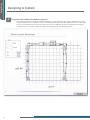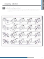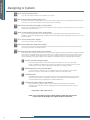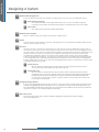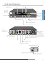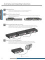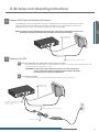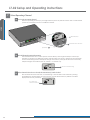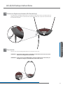
1
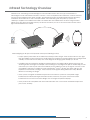
Dear Valued Customer, Thank you for choosing Listen! All of us at Listen are dedicated to provide you with the highest quality products available. We take great pride in their outstanding performance because we care that you are completely VDWLVÀHG7KDW·VZK\ZHLQGHSHQGHQWO\FHUWLI\WKHPWRWKHKLJKHVWTXDOLW\ standards and back them with a limited lifetime guarantee. We stand ready to answer any questions you might have during installation or in the operation of our products. Should you experience any problems whatsoever with your Listen products, we are ready to help you in any way we can with prompt, HIÀFLHQWFXVWRPHUFDUH%HFDXVHDW/LVWHQLW·VDOODERXW\RX$QGVKRXOG\RX have any comments on how we might improve our products or our VHUYLFHZH·UHKHUHWROLVWHQ +HUH·VKRZWRUHDFKXV +1.801.233.8992 +1.800.330.0891 North America +1.801.233.8995 Fax [email protected] www.listentech.com Thank you and enjoy your listening experience! %HVWUHJDUGV Russell Gentner and the Listen Team • In the few instances where repairs were needed, 99% of all clients indicated that they were happy with repair turn-around-times and 85% of the time, clients were without their product for less than 10 days! • Overall client satisfaction of working with Listen was rated 4.8 out of 5. • “Please continue with your excellent attitude toward customer satisfaction. You guys are great!” ´,·YHQHYHUKDGVXFKJRRGVHUYLFHIURPDQ\FRPSDQ\.HHSXSWKHJRRGZRUNµ • “You stand behind your product wonderfully.” $VVLVWLYH/LVWHQLQJ/DQJXDJH,QWHUSUHWDWLRQ6RXQGÀHOG7RXU*URXS&RQIHUHQFLQJ Design Guide Infrared Technology Overview System Overview Designing a System Design Tools 37 38 43 54 55 57 58 78 89 90 91 95 101 102 107 110 115 LR-42/LR-44 4-Channel IR Receivers 6SHFLÀFDWLRQV LR-42 Quick Reference Page LR-44 Quick Reference Page Setup Instructions Operating Instructions Locking Instructions Programming Instructions Programming Examples Programmable Features Detailed Descriptions %DWWHU\&KDUJLQJ,QIRUPDWLRQ Accessories for LR-42/LR-44 LA-350/LA-351 8-Unit IR Receiver Storage/Charging Cases /$6SHFLÀFDWLRQVDQG)HDWXUHV /$6SHFLÀFDWLRQVDQG)HDWXUH LA-350 Charging Requirements/Instructions Cord Tidy Rack 137 139 141 141 141 Supplementary Supplementary Supplementary Information Troubleshooting Frequently Asked Questions Compliance Information Warranty Contacting Listen 125 128 LA-350/351 LA-350/351 LR-42/44 LR-42/44 LR-42/44 LA-140 LA-140 LA-140 IR Radiator 6SHFLÀFDWLRQV Quick Reference Page Setup Instructions LED Indications Mounting your Radiator Accessories for LA-140 LT-82 LT-82 Stationary IR Transmitter 6SHFLÀFDWLRQV %ORFN'LDJUDP Quick Reference Page Setup and Operating Instructions Accessories for LT-82 5 6 9 21 Design Guide Guide Design Stationary Infrared Table of Contents Infrared Technology Overview System Overview Designing a System Design Tools 5 6 9 21 Design Guide Guide Design Stationary Infrared Design Guide Table of Contents Design Design Guide Guide Design Guide Guide Design Infrared Technology Overview Infrared or “IR” technology uses infrared light to transmit audio without wires. This type of transmission is advantageous to RF transmission because it is secure, it is not susceptible to RF interference, and one receiver can be used for multiple rooms within a facility. The transmitter accepts an audio signal and then frequency modulates an RF carrier at 2.3, 2.8, 3.3 and/or 3.8MHz. This carrier along with DC power (to power the radiator) is supplied to the radiator via cables. The carriers are then radiated into the room using IR emitter diodes. This is the same technology used by the remote control of your TV set. A receiver then receives the IR light and demodulates the carrier. Radiator Audio Source 1 2 3 4 Receiver IR Transmitter :KHQGHVLJQLQJDQ,5V\VWHPLWLVLPSRUWDQWWRNHHSWKHIROORZLQJLQPLQG ,QRSHQVSDFHZKHQWKHUHDUHQRUHÁHFWLYHVXUIDFHV,5LVOLQHRIVLJKW,IWKHUHFHLYHUFDQQRW´VHHµOLJKW IURPWKHUDGLDWRULWZLOOQRWUHFHLYHWKHDXGLRVLJQDO,WLVLPSRUWDQWWRSURYLGHVXIÀFLHQW,5FRYHUDJHZLWKLQ a facility so users will not have drop outs of the IR signal. This design guide will help you do this. ,QIDFLOLWLHVWKDWKDYHUHÁHFWLYHDQGOLJKWHUFRORUHGVXUIDFHVWKH,5OLJKWZLOOEHUHÁHFWHGDQG\RXFDQ achieve greater coverage. For example, when emitting in a very large room (like an exhibit hall) you will notice that you need to point the receiver directly at the radiator to pick up the signal. However, when the radiator is placed in a smaller room (for example 50 ft2/14.6 m2 square) with white walls you will H[SHULHQFHPXFKEHWWHUFRYHUDJH7KLVLVEHFDXVHWKH,5VLJQDOLVEHLQJUHÁHFWHGLQPDQ\GLIIHUHQW directions, increasing coverage. • Listen systems use higher modulation frequencies that make the system less susceptible to light LQWHUIHUHQFHIURPÁXRUHVFHQWOLJKWVDQGRWKHUVRXUFHV+RZHYHUWKHV\VWHPLVQRWLPPXQHIURP interference from sources that create IR light such as sunlight and plasma displays. • Listen products are compatible with other manufacturers who use the same modulation frequencies (2.3, 2.8, 3.3, 3.8 MHz). 5 Design Design Guide Guide System Overview 7KHUHDUHWKUHHPDLQFRPSRQHQWVRIDQ\6WDWLRQDU\,5V\VWHPWKHWUDQVPLWWHUUDGLDWRUHPLWWHUDQGUHFHLYers. LT-82 Transmitter LA-140 Radiator 1 2 3 1 2 3 4 4 LR-42 LR-44 Single Channel System A single channel system consists of one LT-82 transmitter and one or more radiators. The diagram below shows such a system with one radiator. The radiator is powered from the power supply at the transmitter. This power supply can supply enough power for the LT-82 and up to two LA-140 radiators. If you need more than two radiators, you will need more power supplies. This is discussed later in this document. Power is supplied from standard CAT-5 cable while RF from the transmitter is delivered using 50-ohm RG-58 coaxial cable. The radiator is supplied with 25 feet (7.6 meters) of CAT-5 and RG-58 coaxial cable. LT-82 Stationary IR Transmitter LA-140 IR Radiator 1 2 3 4 LR-42 IR Stetho Receiver Power – CAT-5 Cable IR RF – RG-58 50 ohm Cable Mounting hardware for radiator included with radiator 1 2 3 4 LR-44 IR Lanyard Receiver 6 Design Guide Guide Design System Overview Multiple Channel System A multiple channel system consists of two to four LT-82 transmitters and one or more radiators. The diagram EHORZVKRZVVXFKDV\VWHPZLWKWZRUDGLDWRUV7KHUDGLDWRUVDUHSRZHUHGIURPWKHSRZHUVXSSO\IURPWKHÀUVW transmitter. This power supply can supply enough power for the LT-82 and two LA-140 radiators. If you need more than two radiators, you can use the power from the other transmitters. In this example, the four transmitter power supplies can supply enough power for up to eight LA-140 radiators. This is discussed later in this document. Power issupplied from standard CAT-5 cable while RF from the transmitter is delivered using 50-ohm RG-58 coaxial cable. Each radiator is supplied with 25 feet (7.6 meters) of CAT-5 and RG-58 coaxial cable. Up to four LT-82 transmitters can be daisy chained together (using RG-58 cable) to create a multi-channel system Up to 100 LA-140 radiators can be daisy chained together (using RG-58 cable) to provide sufficient IR power for most applications LA-140 IR Radiator Power – CAT-5 Cable IR RF – RG-58 50 ohm Cable 2 1 3 4 LR-42 IR Stetho Receiver LT-82 Stationary IR Transmitter RF – RG-58 50 ohm Cable LA -89 RG-58 Multi-carrier Interconnection Cable (included) Power – CAT-5 Cable IR LT-82 Stationary IR Transmitter 1 LA-140 IR Radiator LT-82 Stationary IR Transmitter 2 3 4 LR-44 IR Lanyard Receiver Radiator Power: Radiators can be powered from the LT-82 (up to two radiators) or an additional power supply (LA-205) can power up to two radiators Radiator RF: RF from the last LT-82 must be daisy chained from radiator to radiator LT-82 Stationary IR Transmitter 7 Design Design Guide Guide System Overview Key Concepts of Designing a Stationary IR System 1 Each LT-82 transmitter used can power two LA-140 radiators Each LT-82 transmitter used can power up to two LA-140 radiators. If you design a system that requires more radiators than the transmitters can power, you need to order additional LA-205 power supplies. Each LA-205 can power up to two LA-140 Radiators. 2 Up to four LT-82 transmitters can be interconnected to create up to a four channel system Up to four LT-82 transmitters can be interconnected to create up to a four channel system. For the system, there are two RF outputs provided for connection to the radiators. Each of these two outputs is referred to as the “Radiator Daisy Chain.” RG-58 coaxial cable is used to interconnect the RF in the radiator daisy chain. You can connect as many radiators in the daisy chain as you need. NOTE: Adding additional transmitters will decrease radiator coverage. 3 Each radiator requires one RF (RG-58 coax) connection and one power (CAT-5) connection Each radiator requires one RF (RG-58 coax) connection and one power (CAT-5) connection. The RF connection can come from a transmitter or from another radiator. The power connection can come from HLWKHUDWUDQVPLWWHUDUDGLDWRURUIURPDSRZHUVXSSO\DVORQJDV\RXGRQ·WH[FHHGWKHFDSDFLW\ 4 Listen has provided mounting hardware for most LA-140 mounting situations To make it easy for you to design, specify and install a system, Listen has provided mounting hardware for most mounting situations including wall, ceiling, corner, desk, tripod and mic stands. To double the radiation power you can vertically or horizontally mount two radiators together using the LA-342 dual radiator mounting brackets. This includes coaxial RF and CAT-5 power cables. 5 It is possible that the RF signal arrives to different radiators at different times Due to the higher modulation frequencies, it is possible that the RF signal arrives to different radiators at different times. This delay can cause the IR carriers to add “out of phase” and cause the signal to drop out. To solve this problem, Listen has provided a delay compensation adjustment on each radiator. This design guide will help you calculate the setting for this adjustment. 6 As the number of channels increases, the effective radiated coverage declines As the number of channels increases, the effective radiated coverage declines. For example, a two channel system will have half the coverage of a single channel system. If is important to increase the number of radiators for multiple channel systems. 7 The coverage patterns provide coverage of the system assuming no reflection 7KHFRYHUDJHSDWWHUQVSURYLGHGE\/LVWHQSURYLGHFRYHUDJHRIWKHV\VWHPDVVXPLQJQRUHÁHFWLRQ,Q addition, the radiator has been under-rated to account for system degradation as the IR emitting LEDs age over time. It is important to design the system based on these coverage patterns and not by trial and error. The reason for this is that the coverage pattern will be stronger when the radiator is new. A system that has adequate coverage today may not have adequate coverage in the future if not GHVLJQHGDFFRUGLQJWRWKHVSHFLÀHGFRYHUDJHSDWWHUQVRIWKHUDGLDWRU 8 The maximum length of CAT-5 power cable CAT-5 power cable should never exceed 1000 feet from the source power supply. 9 The maximum length of coaxial RF cable Coaxial RF signal cable should never exceed 1000 feet from the source transmitter. 8 Design Guide Guide Design Designing a System 1 Determine the number of audio channels You will need to order one LT-82 transmitter for each audio channel. The Listen system can deliver up to four audio channels simultaneously. 2 Determine the room size and shape <RXVKRXOGHLWKHUPHDVXUHWKHURRPRUXVHWKHDUFKLWHFW·VSODQVWRREWDLQWKLVLQIRUPDWLRQ 3 Complete the room layout worksheet &RPSOHWHWKHURRPOD\RXWZRUNVKHHWIRXQGLQWKHÀQDOVHFWLRQRIWKLVJXLGHSODFLQJWKHORFDWLRQRIWKH transmitters, power supplies and radiators using the worksheet key. The following factors will determine the coverage of the room. 3A Number of radiators and location Except in small rooms it is recommended that at least two radiators be used to ensure good coverage and minimal shading. Listen radiators (when used with Listen receivers) will cover approximately 10,000 ft2 (929 m2) for one channel as indicated in the diagram below (note the coverage decreases as the number of channels goes up). For two channels, one radiator will cover 5,000 ft2 (465 m2) and for four channels, one radiator will cover 2,500 ft2 (232 m2). Horizontal Plane Footprint Pattern (feet) 50 40 30 20 10 Coverage pattern shown in feet 4 TX 0 2 TX 1 TX 10 20 30 40 50 0 10 20 30 40 50 60 70 80 90 100 110 120 130 140 150 You should use the above coverage pattern to determine coverage of each radiator in your system, not by trial and error. The radiator will be stronger when new and therefore is under-rated by 40 percent and the coverage pattern above accounts for this. 40 percent degradation will occur after approximately 8,000 operating hours. 9 Design Design Guide Guide Designing a System Horizontal Polar Pattern Single Channel System Vertical Polar Pattern Single Channel System 10 Design Guide Guide Design Designing a System It is a good idea to provide over-lapping coverage (like in a sprinkling system) of the signal whenever possible to ensure that the signal does not have drop outs. In addition, you should provide special radiator coverage for shaded areas such as under a balcony or in the front of a room where the front mounted radiators do not provide enough coverage. The following diagrams illustrate these concepts. In this example a total of four radiators, one in each corner, ensures good coverage at all locations and orientations. Except in small rooms, it is recommended that at least two radiators are used to prevent shading of the IR signal. 11 Design Design Guide Guide Designing a System If there is an area within a room (such as under a balcony) that is shielded from the main radiation pattern, you will need to provide additional radiator(s) to cover this area. 12 Design Guide Guide Design Designing a System To double the radiator power, it is possible to vertically or horizontally mount two radiators together using the /$'XDO5DGLDWRU0RXQWLQJ%UDFNHWVROGVHSDUDWHO\7KLVLVKLJKO\UHFRPPHQGHGLQODUJHUURRPV RAD 1 RAD 2 3B Height of Radiators It is critical to mount the radiators at the proper height. If the radiator is mounted too low, the coverage SDWWHUQZLOOEHWRRVPDOOWRSURYLGHVXIÀFLHQWORQJWKURZFRYHUDJH,IWKHUDGLDWRULVPRXQWHGWRRKLJKWKH required angle of the radiator will cause the radiation pattern to be compromised. The best height of the radiator is about 16 ft2 (5 m2IURPWKHÁRRU 3C Radiator Mounting Angle The mounting system for Listen LA-140 radiators allow you to mount the radiator in 15 degree increments. The best angle depends on the shape of the room and the orientation of the radiator to the seats within the room. In general, mounting angles of 15 and 30 degrees provide the best coverage. 13 Design Design Guide Guide Designing a System 4 Determine the number of radiators required 'HWHUPLQHWKHQXPEHURIUDGLDWRUVUHTXLUHGEDVHGRQWKHVL]HDQGVKDSHRIWKHURRP%DVHGRQVWHSWZRLW is recommended that you draw the room out indicating the location of each radiator in the room and cable runs from the transmitter(s) and power supplies (if any) to the radiator. We have provided the room layout ZRUNVKHHWIRU\RXWRGRWKLVWRZDUGVWKHEDFNRIWKLVGHVLJQJXLGH6HHH[DPSOHEHORZ 14 Design Guide Guide Design Designing a System 5 Complete the system layout worksheet Complete the system layout worksheet for Power and RF cable lengths, delay compensation, required number of power supplies, and height and angle of radiators. Refer to the system layout worksheet example below. 15 Design Design Guide Guide Designing a System 5A Cross out the LT-82 transmitters Cross out the LT-82 transmitters not required in your system. 5B Determine how many radiators will be used Determine how many radiators will be used on each radiator daisy chain by reviewing the room layout worksheet. Cross out the unused radiators on the system layout worksheet. 5C Write in the coaxial RF cable lengths for each radiator Write in the coaxial RF cable lengths for each radiator used in the spaces provided. Review your room layout worksheet for this information. 5D Draw a connecting line from the power supply output Draw a connecting line from the power supply output of the LT-82 transmitter(s) and the LA-205 power VXSSOLHVWRHDFKRIWKHUDGLDWRUV.HHSLQPLQGWKDWHDFKWUDQVPLWWHUDQGSRZHUVXSSO\FDQSRZHUXSWRWZR LA-140 radiators. 5E Cross out the unused power supplies Cross out the unused power supplies. 5F Write in the CAT-5 power supply cable lengths Write in the CAT-5 power supply cable lengths for each radiator used in the spaces provided. Review your room layout worksheet for this information. 5G Determine the delay compensation for each radiator Now determine the delay compensation for each radiator using the Delay Compensation Calculator located in the back of this design guide. The correct setting of the delay compensation is necessary only in systems where there is overlap in coverage between two or more radiators. Write the delay setting on the System /D\RXW:RUNVKHHW7KHGHOD\VHWWLQJIRUHDFKUDGLDWRULVGHWHUPLQHGXVLQJWKHFDOFXODWRUDQGDVIROORZV 1 Distance of Furthest Radiator (DFR) Determine which radiator is the furthest from the transmitter on one of the two daisy chains. Calculate the distance from the furthest radiator to the transmitter and record it in WKHÀUVWFROXPQRIWKHGHOD\FRPSHQVDWLRQFDOFXODWRU6HHH[DPSOHEHORZ 2 Radiator Distance from Transmitter (RDT) For each radiator, determine the overall distance from the transmitter to the radiator. Record the value of each radiator in the RDT column. See example below. 3 Cable Delay (CD) Determine and record the propagation delay of the coaxial cable being used. For Listen coaxial cable the delay is 1.54 ns/ft or 5.05 ns/m. This information can be obtained from WKHVSHFLÀFDWLRQVKHHWVVXSSOLHGE\WKHFDEOHPDQXIDFWXUHU 4 Calculate the delay setting for each radiator Now calculate the delay setting for each radiator using the Delay Compensation Calculator. The calculator uses the following formula to determine the delay setting of HDFKUDGLDWRU Delay Setting = (DFR – RDT) x CD / 25 NOTE: If your calculations suggest a delay setting greater than nine, please contact Listen Technologies tech support for more information. 16 Design Guide Guide Design Designing a System 6 Complete the system materials worksheet Complete the system materials worksheet that determines the quantity of each part number required for your V\VWHP8VHWKH5RRPDQG6\VWHP/D\RXW:RUNVKHHWVWRÀOOLQWKLVIRUPIRXQGLQWKHODVWVHFWLRQRIWKLVJXLGH 6A Transmitters Fill in the number of transmitters required. Each transmitter includes a short piece (15 inches) of RG-58 coaxial RF cable for multiple channel installation interconnections. You do not need to order this cable. 6B Transmitter Rack Mounting Fill in the number of rack mounting kits required. One rack mount kit can mount two LT-82 transmitters. 6C Radiators Fill in the number of each type of radiator required. Each radiator comes with mounting brackets for most types of installation. In addition, the radiator comes with 25 ft (7.6 m) of coaxial RF and CAT-5 power cables. 17 Design Design Guide Guide Designing a System 6D Radiator Mounting Options Since the radiator comes with most radiator mounting options, there are only two additional choices. 1 Dual radiator mounting The LA-342 dual radiator mounting bracket allows you to mount two radiators together (vertically or horizontally). This includes short lengths of coaxial RF and CAT-5 power cables. 2 Floor stand 7KH/$LVDÁRRUVWDQGIRUSRUWDEOHDSSOLFDWLRQV 6E Radiator Power Supplies Fill in the number and type of LA-205 power supplies required (if any). 6E Cables From the System Layout Worksheet, insert the cable lengths for the preassembled coaxial RF cables (LA-391) and CAT-5 power cables (LA-393). 6F Receivers There are two types of receivers to choose from. You may want to choose a combination of both types of receivers. The stetho type receiver makes it simple to dispense the units and prevents cord tangling. However, the stetho style for some guests is uncomfortable especially for prolonged time periods. The advantage of the lanyard receiver is that you can use many types of different earphones. However this can make it more complicated for distributing and the cords can become tangled. Each receiver comes with an alkaline battery compartment (no batteries). You will need to decide whether to use alkaline AAA batteries (LA-363) or a rechargeable battery pack (LA-364). Alkaline batteries will last about 30 hours while the rechargeable batteries will last about 15 hours. If you order the rechargeable battery packs, you will need to order the 8-Unit Charging/Storage Station (LA-350). 1 Stetho Receiver Fill in the number of LR-42 Stetho receivers required and the appropriate battery options. <RXFDQDOVRRUGHUH[WUDUHSODFHPHQWWLSV/$TW\ 2 Lanyard Receiver Fill in the number of LR-44 lanyard receivers required and the appropriate battery options. <RX·OODOVRQHHGWRFKRRVHWKHTXDQWLW\DQGW\SHRIHDUSKRQHV/LVWHQKLJKO\UHFRPPHQGVWKH (DU6SHDNHU/$6WHUHR+HDGSKRQHV/$DQGWKH%HKLQGWKH+HDG+HDGSKRQHV (LA-170). Also, it is a good idea to order a quantity of Neck Loops (LA-166) for customers with T-coil equipped hearing aids. 6G Charging/Storage Options If you chose rechargeable battery packs for receivers, you need to order the appropriate quantity and type RI8QLW&KDUJLQJ6WRUDJH6WDWLRQV/$,IQRWLW·VDJRRGLGHDWRRUGHUWKH8QLW6WRUDJH6WDWLRQ/$ 7KLVVLPSOLÀHVWKHGLVSHQVLQJDQGVWRUDJHRIUHFHLYHUV%RWKWKH/$DQG/$FDQEHSHUPDQHQWO\ mounted on a table or on a wall (vertically or horizontally). 6H Other Accessories )RU86FXVWRPHUV/LVWHQRIIHUVWKH$'$&RPSOLDQFH6LJQDJH.LW/$7KLVDLGVLQFRPSO\LQJ with US ADA regulations. 18 Design Guide Guide Design Notes 19 KEY CAT-5 RG-58 LA-140 LT-82 Room Layout Worksheet Design Guide LA-140 Design Guide LT-82 21 Design Guide Guide Design System Layout Worksheet 23 Design Guide LA-140 Design Guide LT-82 25 Design Guide Guide Design System Materials Worksheet Transmitters Description Stationary IR Transmitter Power Cord USA Part Number LT-82-01 UK LT-82-02 Euro LT-82-03 Quantity Transmitter Rack Mounting Description Universal Rack Mount Kit (Mounts two LT-82 units) Part Number LA-326 Quantity Radiators Description Stationary IR Radiator Color Grey Part Number LA-140-GY White LA-140-WH Quantity Radiator Mounting Options Description Dual Radiator Mounting Bracket Part Number LA-342 IR Radiator Floor Stand LA-337 Quantity Radiator Power Supplies Required Description IR System Power Supply Power Cord USA Part Number LA-205-01 UK LA-205-02 Euro LA-205-03 Quantity Cables (length in feet) Stetho Receiver Description BNC/RG-58 Coaxial Cable Preassembled (RF) RJ-45/CAT-5 Cable Preassembled (Power) Part Number LA-391 LA-393 Cable 1 Cable 2 Cable 3 Cable 4 Cable 5 Cable 6 Cable 7 Cable 8 Cable 9 Cable 10 Cable 11 Cable 12 Note: Each radiator includes 25 feet (7.6 meters) of RG-58 coaxial RF cable and CAT-5 power supply cable. Description Stetho Receiver Part Number LR-42 Alkaline Batteries LA-363 Replacement Eartips (20) LA-151 Quantity Receivers Description Lanyard Receiver Rechargeable Battery Pack LA-364 Lanyard Receiver Part Number LR-44 RechargeAlkaline able Battery Batteries Pack LA-364 LA-363 Ear Speaker LA-164 Stereo Headphones LA-165 Behind-the -Headphones Neck Loop Single Ear Bud Dual Ear Buds LA-170 LA-166 LA-161 LA-162 Quantity Charging/Storage Stations Description 8-Unit Charging/Storage Station Power Cord USA UK Euro Part Number LA-350-01 LA-350-02 LA-350-03 8-Unit Storage Station N/A LA-351 Quantity Other Accessories Description ADA Compliance Signage Kit (US Only) Part Number LA-304 Quantity 27 LT-82 User’s Manual Table of Contents 6SHFLÀFDWLRQV %ORFN'LDJUDP Quick Reference Page Setup and Operating Instructions Accessories for LT-82 37 38 43 Design Guide LT-82 Design Guide LT-82 LT-82 Package Contents • LT-82 IR Transmitter • LA-205 Power Supply • LA-89 IR Interconnection Cable ,56\VWHP'HVLJQ*XLGHDQG8VHU·V0DQXDO • LT-82 Quick Reference Card LT-82 IR Transmitter LA-89 IR Interconnection Cable LA-205 Power Supply /LVWHQ&RQÀJXUDWLRQV • LT-82-01 (North America) /78. • LT-82-03 (Euro) 33 /76SHFLÀFDWLRQV $UFKLWHFWXUDO6SHFLÀFDWLRQ 7KH6WDWLRQDU\,57UDQVPLWWHUVKDOOEHFDSDEOHRIEURDGFDVWLQJRQIRXUPRQRRUVWHUHRFDUULHUVDQG0+]&KDQQHO selection shall be capable of being locked. Multiple transmitters shall be capable of being daisy-chained together to transmit up to four channels simultaneously. The transmitter shall have a timer that shuts off the carriers after 30 minutes when no audio is present at the transmitter. The transmitter shall have a SNR of 60 db or better. The device shall have an audio frequency response of 63 Hz to 15 kHz, +/- 3db. It shall have two mixing audio inputs, one balanced XLR/phone input and one unbalanced RCA input. The device shall KDYHWKHIROORZLQJDXGLRFRQWUROVLQSXWOHYHOWUDQVPLWOHYHOFRQWRXUOHYHODQGVWHUHRRQRIIFRQWURO7KHGHYLFHVKDOOKDYHDQDXGLR processor that is capable of automatic gain control and limiting. The transmitter shall provide power for up to two radiators over &$7FDEOH7KH/7LVVSHFLÀHG RF RF Input Compliance ** All system specifications are wireless end-to-end System Frequency Response 63Hz - 15kHz (+/- 3dB) Mono: >60dB System Signal to Noise Ratio (A-weighted) Stereo: >52dB System Distortion <2% total harmonic distortion (THD) Mono Input (Rear Panel). Female-XLR and 1/4 in combo connector, balanced, 0/Audio Input 1 55dBu (line/mic) nominal input level adjustable; -30/+21dBu (mic/line) maximum input level; impedance 20k/1k ohms (line/mic); phantom power +12VDC Stereo or Mono Input (Rear Panel). (Two) Phono connectors, unbalanced, -10/+10dBu Audio Input 2 nominal input level adjustable, +30dBu maximum, impedance 100k ohms Audio Processing Compression can be turned on/off. Slope adjustable from 1:1 to 4:1. Default 2:1 Contour Cuts and boosts frequencies above 5 kHz Input 1 and Input 2 Mixed Output (Rear panel). Two (2) Phono connectors, unbalCombined Audio Output (Mix) anced, -10dBu nominal output level, +19dBu maximum, impedance 10 ohms. Front panel. (One) 3.5mm connector, unbalanced, adjustable output level, +7dBu Headphone Output (Monitor) maximum, impedance 10 ohms. 100mW, 32 ohms, 3.5mm stereo. Rear Panel Internal Adjustments Programming Power, Test Tone on/off, Channel up/down, Input Level, Transmit Level, Contour, Headset Level Input 1 Level (Line, Mic, Mic-Phantom Power), Input 2 Level (-10/+10 dBu) Compression ratio for audio processor Stereo on/off, Processing on/off Unit Power Input 1, Input 2, Transmit Level Stereo Processing RF Carrier LCD Display Test Tone Red LED illuminates when the unit is powered up (front panel) Indicates Input 1, Input 2, and Transmit audio levels. 10 segment LED’s (8 green, 2 red) Indicated by a green LED when on (front panel) Indicated by a green LED when on (front panel) Indicates carrier is active on the LCD Display (front panel) Channel designation, lock status, RF Carrier, programming (front panel) Red LED illuminates when test tone enabled (front panel) Front Panel Controls Indicators In-line switching mode power supply, Listen part number LA-205 Input: 100-240 VAC, 47-63 hz Output: 30 VDC, 1.5 A Output Connector: RJ-45 Compliance: UL and CE Listed Two (2) RJ-45 jacks. For remote powering up to 2 radiators. North America, Type B, (LT-82-01) Power Supply Power Power Output: Physical Power Line Cord Asia, UK, Type G, (LT-82-02) Euro type J, (LA-82-03) Dimensions (H x W x D) Color Unit Weight Unit Weight with LA-205 Power Supply Shipping Weight 1.75 x 8.50 x 9.13 in. (4.5 x 21.5 x 23 cm) Grey with White Silk Screening 2.6 lbs. (5.7 kg) 3.8 lbs. (8.3 kg) 4.4 lbs. (9.7 kg) One rack space height, 1/2 rack space wide. One or two transmitters can be mounted in one rack space. Optional rack mount (LA-326) not included. Rack Mounting Environmental LT-82 Selectable: 2.3 MHz, 2.8 MHz, 3.3 MHz, 3.8 MHz Four channels. Selectable one channel per transmitter (mono or stereo) Carrier will shut off when no audio is present for 30 minutes to preserve radiator life. +/- .005% stability 0 to 50C 50 PPM (Two (2) BNC connectors, for connection to radiator(s) and/or additional transmitter(s). 50 mV, 50 ohm, -15 dBm One (1) BNC connector, for connection from additional transmitter(s). 50 mV, 50 ohm, -15 dBm FCC Part 15, Industry Canada, CE, RoHS RF Output Audio Design Guide LT-82 Design Guide LT-82 Specification Carrier Frequencies Number of Channels Carrier Shut Off0 Frequency Accuracy Transmitter Stability Temperature - Operation Temperature - Storage Humidity -10 C (14 F) to +40 (104 F) -20 C (-4 F) to +50 (122 F) 0 to 95% relative humidity, non-condensing •Specifications are subject to change without notification. 35 LT-82 Block Diagram POWER 3.5MM Stereo On Off Design Guide LT-82 Design Guide LT-82 Red LED 115/230VAC 50/60hz Universal Power Supply LA-205 (provided) CHANNEL SELECT HEADPHONE Up Volume 30VDC, 1.5A Down Power Supply CPU Module Automatic Overload Protection Terminal CAT5 Transmit Level Meter Listen LCD Display Backlit DC Out Compression Ratio (internal adjustment) RF IN Transmitter RF Board Stereo Generator Pre-emphasis Processing OUT BNC Green LED Transmit LEVEL Off On Green LED CONTOUR On Functions controlled by the CPU Module PROCESS STEREO Input 1 VU Meter Off Input 2 VU Meter Input Level POT Front Panel 12VDC Mic Phantom Pwr Mic Line Input 1 Level Select Line, Mic, Mic -phantom Pwr Input 2 Level Select -10dBu, +10dBu +10 -10 +10 Off -10 Test Tone Button Front Panel On Red LED 400Hz TEST TONE Female XLR-1/4” Combo Connector 2/Tip 3/Ring INPUT 1 Mono Only 1/Sleeve Phono Phono INPUT 2 Mono/Stereo 36 Phono OUTPUT Mono/Stereo LT-82 Quick Reference 7UDQVPLW/HYHO,QGLFDWRU6KRZVPL[HGDXGLROHYHO 3URFHVV/(',QGLFDWHVDXGLRSURFHVVLQJPRGHLVDFWLYH 6WHUHR/(',QGLFDWHVVWHUHRPRGHLVDFWLYH ,QSXW/HYHO,QGLFDWRUV6KRZV,QSXW and Input 2 levels. ,QSXWDQG Adjust audio input levels of Input 1 and Input 2 here Design Guide LT-82 Design Guide LT-82 /&''LVSOD\ See LCD Display quick reference 0RQLWRU-DFN Plug in a headset to monitor audio 3RZHU212)) 7HVW7RQH$FWLYDWHVD tone to aid system setup &KDQQHO6HOHFW8SDQG'RZQ8VHWRVHOHFW FKDQQHO%XWWRQVDOVRXVHGIRUSURJUDPPLQJ functions &RQWRXU(TXDOL]DWLRQDGMXVWPHQW boosts or cuts high frequencies 7UDQVPLW/HYHO$GMXVWVPL[HGDXGLROHYHOV 5),QSXW Input additional RF signal here for multi-channel systems ,QSXW%DODQFHG input for connection of a line level or PLFURSKRQH accepts either a XLR or ¼” phono plug 5)2XWSXWV2XWSXW5) signal to radiator(s) and/or additional LT-82 ,QSXW/HYHO6ZLWFK6HWVZLWFKIRUOLQHRUPLFOHYHO Phantom power available in Mic-PH Power position ,QSXW/HYHO6ZLWFK6HWVZLWFKWR match the level of your Input 2 source 3RZHU,QSXW&RQQHFWSRZHU supply here (included) ,QSXW$XGLRLQSXWV stereo or mono $XGLR2XWSXWV,QSXWDQG Input 2 mixed audio outputs 3RZHU2XWSXWV&DQEHXVHG to power up to two radiators &KDQQHO'LVSOD\'LVSOD\VZKDW channel the LT-82 is currently on 5)RXWSXWLQGLFDWRU,QGLFDWHV transmitter is outputting RF 3URJUDP0RGH,QGLFDWHVWKHXQLW is in program mode /RFN,FRQ,QGLFDWHVWKHXQLW