1
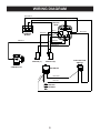
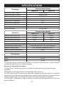
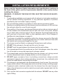
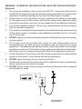
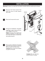
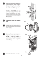
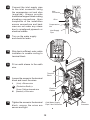
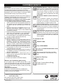
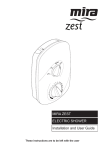
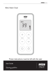
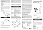
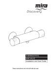
Mira Sport Thermostatic
9.0 & 9.8 kW
For SPARES, ADVICE
or REPAIRS
Please call us on
0844 571 5000
(UK Only)
These instructions must be left with the user
Installation Guide
1
INTRODUCTION
Thank you for purchasing a quality Mira Sport Thermostatic Electric Shower. To enjoy
the full potential of your new shower, please take time to read this guide thoroughly,
and keep it handy for future reference.
Products manufactured by Kohler Mira Ltd are designed to be safe provided, that
they are installed used and maintained in good working order, in accordance with
our instructions and recommendations.
Follow all warnings, cautions and instructions contained in this guide, and on or
inside the shower.
Mira Sport Thermostatic electric showers have separate controls for power
selection and for temperature/flow adjustment. A unique flow regulator stabilises
any temperature changes caused by water pressure fluctuations, which can result
from taps being turned on or off or toilets being flushed.
When this shower has reached the end of its serviceable life, it should be disposed
of in a safe manner, in accordance with current local authority recycling, or waste
disposal policy.
Mira Sport Thermostatic models covered by this guide:
Product
Model Number
Colour
Sport Thermostatic 9.0
J03I
White/Chrome
Sport Thermostatic 9.8
J03J
White/Chrome
Guarantee
The Mira Sport has been designed for domestic use only, Mira Showers guarantee
the Mira Sport against any defect in materials or workmanship for a period of two
years from the date of purchase (shower fittings for one year).
For terms and conditions, refer to the back cover of this guide.
Patents and Design Registration
Design Registration:
001259 287-0002, 001259 287-0005
Patents:
GB:
2341667, 2427460, 2404000, 2428286
Ireland: 82835, 85128, 85163, 85912
If you experience any difficulty with the installation of your new shower, then please
refer to “Fault Diagnosis”, before contacting Kohler Mira Limited. Our telephone
and fax numbers can be found on the back cover of this guide.
2
IMPORTANT SAFETY INFORMATION
WARNING - This shower can deliver scalding temperatures if not operated,
installed or maintained in accordance with the instructions, warnings and
cautions contained in this guide and on or inside the appliance.
TO REDUCE THE RISK OF FIRE, ELECTRIC SHOCK OR INJURY:
1. Installation of this shower must be carried out in accordance with these
instructions by qualified, competent personnel.
2. Isolate the electrical and water supplies before commencing installation. The
electricity must be isolated at the consumer unit and the appropriate circuit
fuse removed, if applicable. Mains connections are exposed when the cover
is removed.
3. DO NOT install the shower in areas with high humidity and temperature (i.e. Steam rooms and saunas).
4. DO NOT install the shower where it may be exposed to freezing conditions.
Ensure that any pipework that could become frozen is properly insulated.
5. DO NOT switch the shower on if there is a possibility that the water in the
shower is frozen.
6. DO NOT switch the shower on if water starts leaking from the shower case.
Isolate the electrical supply to the shower immediately.
7. DO NOT connect the outlet of the shower to any tap, control valve, trigger
handset or showerhead other than those specified for use with this shower.
Only Kohler Mira recommended accessories should be used.
8. The water supplies to this product must be isolated if the product is not to be
used for a long period of time. If the product or pipework is at risk of freezing
during this period they should also be drained of water.
9. DO NOT perform any unspecified modifications to the shower or its
accessories. When servicing only use genuine Kohler Mira replacement
parts.
10. If the shower is dismantled during installation or servicing then upon completion
the product must be inspected to ensure all electrical connections are tight and
that there are no leaks.
11. Read all installation instructions before installing this shower.
12. Upon completion of the installation, make sure that the user is familiar with the
operation of the shower, and leave this guide and the user guide with the owner.
3
PACK CONTENTS
Tick the appropriate boxes to familiarise yourself with the part names and to
confirm that the parts are included.
1 x Mira Sport Thermostatic
Electric Shower
1 x Olive
1 x Compression Nut
3 x Fixing Screws
3 x Wall Plugs
2 x Case Inserts
Documentation
1 x Installation Template
1 x Installation Guide
1 x User Guide
1 x Guarantee Brochure
4
WIRING DIAGRAM
BROWN B
BLUE C
BLUE E
GREEN D
HEATER
TANK
RED K
BROWN J
TERMINAL
BLOCK
BROWN F
RED H
GREEN A
GREEN A
GREEN D
BROWN G
MICRO
SWITCH (L)
MICRO
SWITCH (R)
INLET
CONNECTOR
BLACK M
BLACK N
BL
UE
E
SOLENOID
BLACK L
LED/LED
HOUSING
5
PUSH BUTTON
SWITCH
SPECIFICATIONS
Plumbing
Thermostatic Variant
Sport 9.0
Minimum Dynamic Pressure
Sport 9.8
70 kPa (0.7 bar)
Maximum Dynamic Pressure *
500 kPa (5 bar)
Minimum Static Pressure
20 kPa (0.2 bar)
Maximum Static Pressure *
1000 kPa (10 bar)
Maximum Inlet Temperature
30°C
Minimum Inlet Temperature
Inlet Connection
2°C
1/2" BSP Male / 15 mm Compression Fitting
Maximum Water Hardness
200 ppm CaCO3
Outlet Connection
Electrical
1/2" BSP Male
Thermostatic Variant
Sport 9.0
Sport 9.8
Nominal Power at 230 V ac
8.3 kW
9.0 kW
Nominal Power at 240 V ac
9.0 kW
9.8 kW
Recommended MCB Rating
40 A
45 A
Maximum Supply Cable Size
16 mm²
Recommended RCD Rating
30 mA tripping current
Recommended Isolator Switch
Appliance Sealing Rating
45 A double-pole with 3 mm contact separation
IP X4 - Suitable for installation in Zone 1
Maximum Ambient Temperature
30°C
Minimum Ambient Temperature
2°C
Dimensions
Height
358 mm
Width
215 mm
Depth
90 mm
*A drop tight pressure reducing valve should be installed where dynamic or static pressure
exceeds the figure stated in the Specifications.
European Conformity Information
The Mira Sport Thermostatic range of showers complies with the following European
directives:
2006/95/EC Low Voltage Directive, 2004/108/EC EMC Directive.
The Mira Sport range of showers are high power appliances and are subject to conditional
connection. If the main electrical supply fuse is rated less than 80 Amps, the local electricity
supply company must be contacted to confirm if the electrical supply is adequate.
The Mira Sport Thermostatic range of showers complies with the requirements of the UK’s
water regulations.
6
INSTALLATION REQUIREMENTS
Please read the Important Safety Information and specifications sections at
the front of this guide, and the requirements detailed in this section before
installing the shower.
WARNING - TO REDUCE THE RISK OF FIRE, ELECTRIC SHOCK OR INJURY:
Plumbing
1. The plumbing installation must comply with all national or local water regulations
and all relevant building regulations, or any particular regulation or practice
specified by the local water supply company.
2. Do not install the product in a position in which service access is limited.
3. Decide on a suitable position for the shower (minimum distance of 200 mm from
the ceiling to allow for cover fit and removal).
4. The position of the shower and shower fittings must provide a minimum gap of
25 mm between the showerhead and the spill over level of any bath, shower
tray or basin and a minimum gap of 30 mm between the showerhead and the
spill over level of any toilet, bidet or other appliance with a Fluid Category 5
backflow risk (see diagram on page 8).
5. The shower is suitable for installation within the shower area and is fitted with
a pressure relief valve. It must be positioned over a water catchment area with
the controls at a convenient height for the user.
6. The shower must be fitted to a waterproof flat and even wall surface.
7. DO NOT fit the shower to the wall and tile up to the case.
8. DO NOT seal the gap between the shower and the wall surface.
9. The showerhead should be positioned so that it discharges down the centre
line of the bath or across the opening of a shower cubicle.
10. The showerhead must be directed away from the shower unit, during normal
use the showerhead must not spray directly on to the shower unit.
11. DO NOT apply excessive force to plumbing connections; always provide
mechanical support when making plumbing connections. Any soldered joints
should be made before connecting the shower.
12. This shower is not designed to be plumbed directly from the rear. For rear-entry
supply, add an elbow to the supply pipe and connect as a rising or a falling supply.
13. If pipework and/or electrical cables enter the shower from the rear through a
hole in the wall provision must be made to prevent water ingress back into the
wall structure.
14. Only use the inlet connector supplied with the shower. DO NOT use any other
type of fitting.
7
15. A full bore/non restrictive servicing valve must be fitted in a readily accessible
position adjacent to the shower to facilitate maintenance of the shower. DO NOT use a valve with a loose washer plate (jumper) as this can lead to a
build up of static pressure.
16. A water treatment device should be installed where the water hardness may
exceed 200 ppm. Malfunctions caused by excessive limescale formation are
not covered by this shower’s guarantee (see back page for details).
17. The installation must not cause the hose to be sharply kinked during normal use.
18. DO NOT perform the electrical installation until the plumbing has been completed
and checked for leaks.
Electric
Shower
Zone of
Backflow Risk
25 mm
Minimum
30 mm
Minimum
Toilet or Bidet
FC5
25 mm Minimum
Bath or Shower
Tray FC3
Hand Basin
FC3
Hose Retaining Ring fitted and shower fittings fixed at a suitable height preventing
dirty water backflow.
Note! There will be occasions when the hose retaining ring will not provide a suitable
solution for Fluid Category 3 installations, in these instances an outlet double
checkvalve must be fitted, this will increase the required supply pressure typically by
10kPa (0.1 bar). Double checkvalves fitted in the inlet supply to the appliance cause
a pressure build up, which affect the maximum static inlet pressure for the appliance
and must not be fitted. For Fluid category 5 double checkvalves are not suitable.
8
WARNING - TO REDUCE THE RISK OF FIRE, ELECTRIC SHOCK OR INJURY:
Electrical
1. The electrical installation must comply with BS 7671 (commonly referred to as
the IEE Wiring Regulations) and all relevant building regulations, or any particular
regulation or practice specified by the local electricity supply company.
2. Ensure that all circuit protection devices, switches and cabling is adequate
for the rated current of the shower and that the rating of the electricity supply
company fuse and the consumer unit are adequate for the additional demand.
3. The shower must be earthed. Ensure any supplementary bonding complies
with the relevant regulations.
4. This shower is intended to be permanently connected to the fixed electrical wiring
of the mains system. A separate supply must be provided from the consumer
unit to the shower.
5. DO NOT supply any other electrical equipment including extractor fans or pumps
via this product.
6. This shower must be provided with means for local disconnection that is
incorporated into the fixed wiring in accordance with the relevant local wiring
regulations. This must be a double pole switch, which has at least 3 mm contact
separation in each pole. The switch can be a ceiling mounted pull-cord type within
the shower room or a wall mounted switch fitted in the applicable zone area.
7. A 30mA Residual Current Device (RCD) must be incorporated into the electrical
supply to this shower in accordance with wiring regulations.
8. DO NOT apply excessive force to the terminal block.
9. All electrical connections should be checked for tightness to prevent overheating
before switching on the electrical supply.
10. DO NOT switch on the electrical supply until the plumbing has been completed
and checked for leaks.
ECO
LOW
HIGH
POWER
5
4
6
7
3
8
9
2
1
THERMOSTATIC
9
10
INSTALLATION
Warning! Isolate the electrical and water supplies before installing the shower.
1
Remove the three screws that
hold the cover on and remove
the cover.
2
Remove the service tunnel.
3
Using the installation template
supplied, mark the positions
of the three fixing holes. Note! Ensure that there are
sufficient lengths of supply pipe
and electrical cable to reach the
connection points.
4
Screws
Service
Tunnel
Cover
Screw
Remove the installation template
and drill three holes to suit the
fixing screws and wall plugs.
Caution! Do not drill into cables
or pipes in the wall.
Caution! Do not drill into
buried cables or pipes.
10
5
Determine the direction and route
of the incoming water supply:
falling (entering the shower from
the top), or rising (entering the
shower from the bottom).
NOTE! - DO NOT use an
incoming supply entering the
shower directly from the back.
Add an elbow to the supply pipe
and connect it as a rising or
falling supply.
6
Thoroughly flush the supply
pipe.
7
Rotate the inlet connector to
suit the direction of the incoming
water supply.
8
Upper and lower case inserts are
supplied and should be fitted.
NOTE! - Trim the inserts if
necessary to fit incoming
electrical or water supplies
before fitting.
9
Inlet
Connector
Case
Insert
Case
Insert
Secure the shower to the wall.
11
10
11
Connect the inlet supply pipe
to the inlet connector using
the compression nut and olive
(supplied). Always provide
mechanical support when making
plumbing connections. Upon
completion of the installation
ensure connections and back
case are not under any stress
due to misaligned pipework or
electrical cables.
Inlet
Connector
Olive
Compression
Nut
Inlet Supply
Pipe
Turn on the water supply
and check for leaks.
L
12
Strip back sufficient outer cable
insulation to enable routing to
terminal block.
13
Fit an earth sleeve to the earth
wire.
14
Terminal
Block
Loosen the screws in the terminal
block and insert the wires.
L
(Live) = Brown wire
(Protective Earth) =
Green /Yellow sleeved wire
Electrical
Cables
N (Neutral) = Blue wire
15
N
Tighten the screws in the terminal
block, ensure the wires are
secure and tight.
Cold Water Supply
Pipe / Inlet Connector
12
Outlet
Connector
16
Screws
Ensure the earth bonding
complies with relevant
regulations.
17
Replace the service tunnel.
18
Ensure the control dials are
aligned with the spindles and
replace the cover.
Cover
Spindle
19
Tighten the three cover screws.
Screw
Service Tunnel
20
Do not use alternative screws to
secure the cover. This can cause
internal damage to the appliance.
Do not seal around the back of
appliance.
ECO
LOW
HIGH
POWER
5
4
6
7
8
3
9
2
1
21
THERMOSTATIC
This completes the installation,
follow the guidelines in section
'COMMISSIONING' to prepare
the shower for use.
13
10
COMMISSIONING
1
5
2
6
4
7
3
ECO
LOW
HIGH
3
8
9
2
1
10
POWER
TEMPERATURE
Turn temperature control to Turn power control to low.
the cold position.
4
Switch on the electrical supply.
6 HOT
5
ECO
LOW
HIGH
COLD
0 - 15 secs
POWER
Push START/STOP button. Water flows freely within a Turn power control to Eco.
Light in the button illuminates. few seconds, temperature
remains cool.
7
8
ECO
LOW
HIGH
9
HOT
HOT
COLD
COLD
5 - 10 secs
5 - 10 secs
POWER
Temperature will rise
slightly.
10
Turn power control to High.
11
Temperature will rise further.
12
HOT
5
6
4
7
3
COLD
8
0 - 5 secs
9
2
10
1
TEMPERATURE
A d j u s t t e m p e r a t u r e a s Push START/STOP button. The shower will purge water
required. Flow rate will adjust Light in the button goes out. from its tank for a few seconds..
automatically.
13
Note! A slight hissing sound may be heard from the shower during
operation. High mains water pressure and high shower temperatures
will affect the tone. This is quite normal in use.
Switch off the electrical
supply.
14
FAULT DIAGNOSIS
In the event of a malfunction of the shower, the troubleshooting information below
provides details on possible causes and remedies that may be carried out by qualified,
competent personnel. Non-qualified personnel should refer to the fault diagnosis
section in the users guide.
WARNING
There are no user serviceable components beneath the cover of the shower.
Only qualified competent personnel should remove the front cover
Symptom
Start/Stop
Light is
ON or OFF
Power
Control
Position
Shower fails
to operate.
OFF
ANY
Shower
cycles from
hot to cold.
ON
Unable to
select a
cool enough
shower.
ON
ECO/
HIGH
ANY
Possible Cause
Possible Remedy
Isolator switch in the off
position.
Switch on electrical supply
via the pullcord or wall
mounted switch.
Fuse blown or MCB/RCD
tripped, indicating possible
electrical fault.
Renew the fuse or reset
the MCB/RCD. If fault
persists, contact your
installer.
Service tunnel or cover
not fitted correctly causing
Start/Stop button to not
operate.
Check case inserts are cut
and fitted correctly. Check
services (electrical or
plumbing) are not interfering
with location of service
tunnel or cover.
Showerhead blocked.
Remove and descale
showerhead.
Hose kinked or blocked.
Check hose and replace if
necessary.
Water pressure below
minimum required for
shower operation.
Make sure incoming mains
water stopcock and/or
shower isolating valve is
fully turned on.
Temperature control or
power control setting too
high.
Turn the power control
to Eco or turn the
temperature control until
a cooler temperature is
achieved.
Due to the rise in mains
water supply temperature,
the power control setting
may be too high.
Turn the power control
to Eco or turn the
temperature control until
a cooler temperature is
achieved.
15
Symptom
Start/Stop
Light is
ON or OFF
Power
Control
Position
Showerhead
dripping.
OFF
Operation of
Temperature
Control
has little or
no effect
on water
temperature.
ON
ANY
ECO/
HIGH
Possible Remedy
Insufficient water supply
pressure for shut off.
Minimum static pressure
to ensure shut off and
prevent dripping is 20 kPa
(0.2 bar).
Note! If other appliances
are operating, static
pressure may drop below
20 kPa (0.2 bar). Contact
local water company.
Flow valve faulty.
Replace flow valve.
Water supply pipework
or inlet filter restricted
by a blockage or partial
blockage.
Flush supply pipe. Clean
inlet filter.
Insufficient water supply
pressure/flow for operation.
Contact local water
company. Supply pressure
must be a minimum of 70
kPa (0.7 bar).
Note! If other appliances
are operating, pressure
may drop below 70 kPa
(0.7 bar).
Flow valve faulty.
Replace flow valve.
Heater tank excessively
scaled.
Replace heater tank. In
hard water areas consider
the use of a water
softener.
Showerhead blocked.
Remove and descale
showerhead.
Hose kinked or blocked.
Check hose and replace if
necessary.
Other outlets (e.g. Toilet,
garden hose, washing
machine, etc.) drawing
water while the shower is
being used.
Turn off other appliances
whilst shower is in use.
Showerhead blocked.
Remove and descale
showerhead.
Hose kinked or blocked.
Check hose and replace if
necessary.
Flow valve faulty.
Replace flow valve.
Heater tank failure.
Replace heater tank.
ANY
Low or no
flow.
ON
Possible Cause
16
Symptom
No
change in
temperature
between
Low / Eco /
High setting.
Water will
not turn off.
Shower fails
to produce
hot water
when set on
Eco / High
setting.
Water leaks
from the
bottom of
the case
and there
is no flow
from the
showerhead.
Start/Stop
Light is
ON or OFF
Power
Control
Position
ON
ANY
OFF
ANY
ON
OFF
ECO/
HIGH
ANY
Possible Cause
Possible Remedy
Microswitch failure.
Replace microswitch.
Insufficient mains water
pressure.
Contact local water
company.
Possible failure of flow
valve, microswitch or
heater tank.
Use a suitable device to
check the continuity of
the microswitch or heater
tank and replace parts as
necessary.
Flow valve, solenoid or
Start / Stop switch faulty.
Replace as necessary.
Insufficient water supply.
Contact local water
company.
Possible failure of the
microswitch or thermal
switch.
Use a suitable device to
check the continuity of
the microswitch or heater
tank and replace parts as
necessary.
Hose kinked or blocked.
Check hose and replace if
necessary.
The PRV has been
triggered, (the shower
has a pressure relief
valve assembly to reduce
damage if the outlet is
blocked or the shower is
frozen). When the relief
valve operates a small
rubber ball is ejected.
Replace heater tank.
17
SERVICING
WARNING
There are no user serviceable parts inside the shower.
Servicing of the shower must only be carried out by qualified, competent
personnel following the instructions provided in this guide and those provided
with any spare part.
Before replacing any parts, ensure that the underlying cause of the malfunction
has been resolved.
Cleaning the Inlet Filter
Screws
Warning! Isolate the electrical and water
supplies before removing the cover.
1
Remove the shower hose.
Note! Retain the hose washer
for further use
2
Remove the three screws that
hold the cover on the shower and
remove the cover.
3
Remove the service tunnel from
the shower.
Cover
Screw
4
Use a suitable spanner to remove
the filter from the inlet connector
assembly. Hold a wrench across
the flats of the inlet connector
assembly to prevent damage to
the connector, whilst removing
the filter.
5
Remove the filter and rinse under
a running tap to remove any
lodged particles. If necessary, use
a kettle descalent in accordance
with the manufacturer ’s
instructions.
6
Hose
Washer
Service
Tunnel
Inlet Filter
Inlet Connector
Assembly
Refit the components in reverse
order.
18
SPARE PARTS
B
1563.719
Thermal Switch
1746.449
Terminal
Block
872.01
Microswitch
(2 pin)
A
1746.444
Switch
Assembly
1746.458 (9.0kW)
1746.459 (9.8kW)
Heater Tank
1563.536
Control Belt
A
A
1829.062
Inlet Filter
1829.063
Inlet
Connector
A
A
1563.538
Temp Cam
& Pulley
416.38
Inlet Clamp
416.51
Coil
B
1563.540
Inlet Valve
A
1746.446
Switch / LED
Assembly
1746.461
Outlet
Connector
1746.448
Service Tunnel
B
1746.460
Cover
1563.522 Cover Seal - not shown
1563.541 Screw Pack - identified 'A'
1746.456 Component Pack - identified 'B'
19
CUSTOMER SERVICE
Guarantee
Your product has the benefit of our manufacturer’s
guarantee which starts from the date of purchase.
To activate this guarantee, please return your completed
registration card, visit our website or free phone 0800
0731248 within 30 days of purchase (UK only).
Within the guarantee period we will resolve defects in
materials or workmanship, free of charge, by repairing or
replacing parts or product as we may choose.
This guarantee is in addition to your statutory rights
and is subject to the following conditions:
● The guarantee applies solely to the original installation
under normal use and to the original purchaser only.
The product must be installed and maintained in
accordance with the instructions given in this user
guide.
● Servicing must only be undertaken by us or our
appointed representative. Note! if a service visit
is required the product must be fully installed and
connected to services.
● Repair under this guarantee does not extend the original
expiry date. The guarantee on any replacement
parts or product ends at the original expiry date.
● For shower fittings or consumable items we reserve
the right to supply replacement parts only.
The guarantee does not cover:
● Call out charges for non product faults (such as
damage or performance issues arising from incorrect
installation, improper use, inappropriate cleaning,
lack of maintenance, build up of limescale, frost
damage, corrosion, system debris or blocked filters)
or where no fault has been found with the product.
● Water or electrical supply, waste and isolation issues.
● Compensation for loss of use of the product or
consequential loss of any kind.
● Damage or defects caused if the product is repaired
or modified by persons not authorised by us or our
appointed representative.
● Routine maintenance or replacement parts to
comply with the requirements of the TMV 2 or TMV
3 healthcare schemes.
● Accidental or wilful damage.
● Products purchased ex-showroom display.
What to do if something goes wrong
If your product does not work correctly refer to this
manual for fault diagnosis and check that it is installed
and commissioned in accordance with our instructions.
If this does not resolve the issue, contact us for help
and advice.
Helpdesk Service - Ring our Customer
Services Team for product advice, to purchase
spare parts or accessories or to set up service
visit. You can contact us via phone or e-mail,
details below. Please provide your model
name, power rating (if applicable) and date
of purchase.
Mira Showers Website (www.mirashowers.
co.uk)
Visit our website to register your guarantee,
download user guides, diagnose faults,
purchase our full range of accessories and
popular spares, or request a service visit.
Spares and Accessories - We hold the largest
stocks of genuine Mira spares and accessories.
Contact us for a price or visit our website to
purchase items from our accessory range and
popular spares.
Service/Repairs - No one knows our products
better than our nationwide team of Service
Technicians. We can carry out service or repair
work to your product both during and after the
guarantee period. Ask about our fixed price
service repairs.
To Contact Us: UK
0844 571 5000
Fax: 01242 282595
E-mail: Visit www.mirashowers.co.uk/
contactus
Mira Customer Services Dept, Cromwell
Road, Cheltenham, Gloucestershire, GL52
5EP
To Contact Us: Eire Only
01 531 9337
E-mail: CustomerServiceEire@
mirashowers.com
Extended Guarantees
A selection of protection plans are available that
enable you to cover repair bills (excludes Eire). Ring
01922 471763 for more details.
Mira is a registered trade mark of
Kohler Mira Limited.
The company reserves the right to alter
product specifications without notice.
1175284-W2-C
FM 14648
20
© Kohler Mira Limited, July 2013