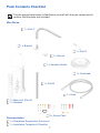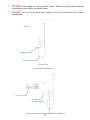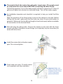
1
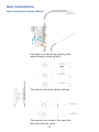
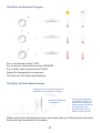
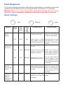
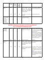
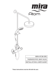
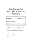
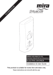
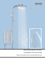
Mira Divisa Electric Shower
Installation and User Guide
These instructions are to be left with the user
1
Contents
Introduction.............................................................................................. 3
Guarantee.................................................................................................. 4
Patents and Design Registration........................................................... 4
Important Safety Information.................................................................. 5
Warning!................................................................................................ 5
Caution!................................................................................................. 6
Pack Contents Checklist......................................................................... 7
Specifications........................................................................................... 8
Installation Requirements....................................................................... 8
Installation.............................................................................................. 11
Installation of Mira Divisa.................................................................... 11
Installation of Overhead and Handset................................................. 14
Commissioning...................................................................................... 16
User Instructions.................................................................................... 19
Fault Diagnosis....................................................................................... 22
Heater Settings.................................................................................... 22
Wiring Diagram....................................................................................... 25
Maintenance............................................................................................ 26
Inlet Filter - Cleaning/Renewing.......................................................... 26
Handset - Cleaning.............................................................................. 27
Spare Parts............................................................................................. 28
Dimensions............................................................................................. 30
Customer Services................................................................................. 31
2
Introduction
Thank you for purchasing a quality Mira product. To enjoy the full potential of your
new product, please take time to read this guide thoroughly. Having done so, keep
it handy for future reference.
The Mira Divisa is an electric shower with separate controls for power selection
and temperature/flow adjustment. A unique valve stabilises temperature changes
caused by water pressure fluctuations. These can result from taps being turned on/
off, or toilets being flushed. Water is either delivered through the main overhead
or a slimline handset which magnetically fixes to the shower unit when not in use.
Water flow to either of the shower outlets is determined by a diverter handle at the
base of the unit
Mira Divisa 9.0 kW
A 9.0 kW 240V AC (8.2 kW 230V AC) heater with overhead and slimline handset.
Supplied complete with flexible hose. Available in white/chrome.
Mira Divisa 9.8 kW
A 9.8 kW 240V AC (9.0 kW 230V AC) heater with overhead and slimline handset.
Supplied complete with flexible hose. Available in white/chrome.
Mira Divisa 10.8 kW
A 10.8 kW 240V AC (9.9 kW 230V AC) heater with overhead and slimline handset.
Supplied complete with flexible hose. Available in white/chrome.
If you experience any difficulty with the installation or operation of your new Electric Shower,
please refer to ‘Fault Diagnosis’, before contacting Kohler Mira Ltd. Our telephone and
fax numbers can be found in the back pages of this guide.
3
Recommended Usage
Domestic
ü
Light Commercial
û
Heavy Commercial
û
Healthcare
û
Guarantee
For domestic installations, Mira Showers guarantee the Mira Divisa against any
defect in materials or workmanship for a period of two years from the date of purchase
(overhead, handset and hose for one year).
For non-domestic installations, Mira Showers guarantee the Mira Divisa against
any defect in materials or workmanship for a period of one year from the date of
purchase.
For terms and conditions refer to section “Customer Services”.
Patents and Design Registration
Design Registration 001065023-0005, -0006
Patents
GB:
Eire:
2 341 667, 2 404 000, 2 428 286.
82835
Patent Applications
UK:
Eire:
2 427 460
2004/0483, 2006/0462, 2008/0289.
4
Important Safety Information
Installation must be carried out in accordance with these instructions, and must be
conducted by designated, qualified and competent personnel.
Warning!
Follow all warnings, cautions and instructions contained in this guide, and
on or inside the appliance.
1.
2.
3.
4.
5.
6.
7.
8.
9.
10.
11.
12.
13.
Products manufactured by us are safe and risk-free, provided that they are
installed, used and maintained in good working order, in accordance with our
instructions and recommendations.
Isolate the electrical and water supplies before connecting to the appliance.
Mains electrical connections are exposed when the cover is removed.
Refer to the wiring diagram before making any electrical connections (refer to
the wiring diagram in this guide).
Make sure that this guide is left with the user.
DO NOT commission this appliance if water leaks from the unit or the heater
tank pressure relief valve (bottom of the tank).
DO NOT fit any form of outlet control (e.g. Trigger handset) as the outlet acts
as a vent for the tank body. Only Mira recommended outlet fittings should be
used.
Make sure all electrical connections are tight, to prevent overheating.
The shower unit must not be fitted where it may be exposed to freezing
conditions. Make sure that any pipework that could become frozen is properly
insulated. Warning, do not operate this appliance if it appears to be frozen,
allow to thaw and then contact your installer before using again.
This product is not suitable for areas with high humidity (i.e steam rooms).
THE APPLIANCE MUST BE EARTHED. MAKE SURE SUPPLEMENTARY
BONDING COMPLIES WITH THE “REQUIREMENTS FOR ELECTRICAL
INSTALLATIONS”.
This appliance is intended to be permanently connected to the fixed electrical
wiring of the mains system.
If the wiring layout is changed or amended, the product functionality and safety
may be affected.
This appliance contains magnets. Users fitted with a heart pacemaker or ICD
should follow their normal safety precautions for products that contain magnets.
The magnets are located down the left side of the main unit. There are no
magnets in the shower handset.
5
Caution!
1.
2.
3.
4.
The electrical installation must comply to “BS 7671 - Requirements for Electrical
Installations”, commonly referred to as the IEE Wiring Regulations - Part 7, or
any particular regulations and practices, specified by the local electricity supply
company.
The plumbing installation must comply with the requirements of UK Water
Regulations/Bye-laws (Scotland), Building Regulations or any particular
regulations and practices, specified by the local water company or water
undertakers.
Make sure that users fully understand how to operate the shower and that it
should be maintained properly in accordance with the instructions given in this
guide.
Anyone who may have difficulty understanding or operating the controls of any
shower should be attended whilst showering. Particular consideration should
be given to:
4.1.
4.2.
4.3.
4.4.
4.5.
4.6.
5.
6.
7.
Children should be supervised to make sure that they do not play with the
appliance.
Sunburn or skin conditions can increase sensitivity to hot water. Users should
make sure that the shower is set to a cooler temperature if required.
If any of the following conditions occur, isolate the electricity and water supplies
and refer to “To contact us”, in the back pages of this guide:
7.1.
7.2.
7.3.
7.4.
7.5
8.
The young.
The elderly.
The infirm.
The disabled.
Anyone who suffers from a medical condition that can result in temporary
incapacity (e.g. epilepsy or blackouts).
Anyone inexperienced in the correct operation of the controls.
If the cover is not correctly fitted and water has entered the appliance
case.
If the case is damaged.
If the appliance begins to make an odd noise, smell or smoke.
If the appliance shows signs of a distinct change in performance,
indicating a need for maintenance.
DO NOT operate if water leaks from the appliance.
When the appliance has reached the end of its serviceable life, it should
be disposed of in a safe manner, in accordance with current local authority
recycling or waste disposal policy.
6
Pack Contents Checklist
Tick the appropriate boxes to familiarise yourself with the part names and to
confirm that the parts are included.
Mira Divisa
1 x Part C
1 x Bracket
1 x Part D
1 x Shroud
1 x Handset Holder
1 x Overhead
1 x Part B
1 x Hose
1 x Main Unit (Part A)
1 x Handset
2 x Screw Pack
Documentation
1 x Guarantee Registration Document
1 x Installation Template & Checklist
7
Specifications
1. Plumbing
• Minimum maintained inlet pressure for 9.0 kW and 9.8 kW, 70 kPa (0.7 bar)
for satisfactory operation.
•
Minimum maintained inlet pressure for 10.8 kW, 100 kPa (1.0 bar) for
satisfactory operation.
•
•
Maximum static inlet pressure 1000 kPa (10 bar).
Minimum static pressure 20 kPa (0.2 bar) to keep the inlet valve closed.
2. Electrical
• The Mira Divisa 9.0 kW requires a 40 Amp circuit protection device.
•
•
•
The Mira Divisa 9.8 kW requires a 45 Amp circuit protection device.
The Mira Divisa 10.8 kW requires a 45 Amp circuit protection device.
The terminal block will accept cable up to 16 mm².
3. Standards and Approvals
• The Mira Divisa complies with all relevant directives for CE marking.
Installation Requirements
1. Plumbing
• When installed in very hard water areas (above 200 ppm temporary hardness)
your installer may advise the installation of a water treatment device, to reduce
the effects of limescale formation. Your local water company will be able to
advise the hardness of water in your area.
•
A non-restrictive (free flowing) isolating valve MUST be fitted in the cold water
supply pipe to allow the complete maintenance of the appliance. Do not use
a valve with a loose washer plate (jumper) as this can lead to a build up of
static pressures.
•
To comply with Water Regulations, two single check valves are fitted to
the outlet of the shower to prevent contamination from backsyphoning.
Double inlet check valves are not required and may cause a pressure build
up which could exceed the maximum static inlet pressure for the appliance.
•
The appliance is suitable for installation within the shower area. It is fitted with
a pressure relief device and must be positioned over a water catchment area
with the controls at a convenient height for all users.
•
The appliance must be fitted on to a finished flat and even wall surface (this
wall surface should be tiled or waterproofed). DO NOT fit the appliance to the
wall and tile up to the case, or apply any type of sealant around the appliance.
For safety requirements, an air gap must be left behind the appliance.
8
•
Avoid layouts where the shower hose will be sharply kinked. This may reduce
the life of the hose.
•
Supply pipework MUST be flushed to clear debris before connecting to the
appliance.
•
To avoid damage to the case when soldered fittings are used, pre-solder the
pipework and fittings before connecting them to the inlet connector assembly.
Refrain from applying excessive force when making any connections. Always
provide mechanical support when making the plumbing connections.
•
The appliance is fitted with a brass inlet compression assembly for connecting
to a 15 mm supply pipe from the top, bottom or back. The fitting of double
checkvalves in the inlet supply to the appliance, can cause a pressure
build‑up, which could exceed the maximum static inlet pressure and damage
the appliance.
2. Electrical
• In a domestic installation, the rating of the electricity supplier’s fuse and the
consumer unit must be adequate for the additional demand. All Mira electric
showers are high power units, it is essential to contact your electricity supplier
to ensure that the supply is adequate for the product. Voltage drop due to
local heavy demand will reduce the shower’s performance.
•
The appliance must be earthed by connecting the supply-cable earth
conductor to the earth terminal. Supplementary bonding: Within the bathroom
or shower room, all accessible conductive parts of electrical equipment and
extraneous conductive parts (metal parts) that are likely to introduce earth
potential, must be electrically bonded in accordance with BS7671.
•
The minimum cable size (cross-sectional area) required should be in
accordance with BS 7671.
•
As a guide only, and in accordance with BS 7671 we recommend close circuit
protection: i.e. 9.8 kW = 45 Amp
•
A 30mA Residual Current Device (RCD) MUST be included in the electrical
circuit. This may be part of the consumer unit or a separate unit.
•
A separate, permanently connected supply must be taken from the consumer
unit to the appliance through a double-pole switch, which has at least 3
mm contact separation. The switch can be a ceiling mounted pullcord type
within the shower room or a wall mounted switch fitted in the applicable zone
area.
9
•
•
DO NOT exert strain on the terminal block. Make sure that the electrical
connections are tightly screwed down.
DO NOT turn-on the electrical supply until the plumbing has been
completed.
700 mm
Isolating Valve
Avoid Sharp Kinks
Shower Tray
Consumer Unit
Double-pole
Isolating Switch
10
Installation
Installation of Mira Divisa
Warning! Turn off the electrical and water supplies before proceeding with the
installation of the Mira Divisa. The electricity must be turned off at the mains and
the appropriate circuit fuse electrically isolated, if applicable.
Remove the three cover retaining
screws.
Remove the cover.
Remove the service tunnel.
Service Tunnel
Determine the direction of the inlet
water supply: top (falling), bottom
(rising), or back inlet.
Note! Make sure that the back inlet
does not go directly back into the wall.
Use a soldered elbow.
Swivel the inlet connector to suit.
Remove the inlet blanking cap. Avoid
trapping the green earth bonding
wire.
11
Thoroughly flush the mains-fed cold water supply pipe. The supply must
be clean and free from debris before connecting the Mira Divisa.
To flush the pipework, turn on the water supply and drain a minimum of 10 litres (2
gallons) of water into a bucket or catchment area. Turn off the water supply.
An installation template and checklist is supplied to help you install the Mira
Divisa.
Mark the positions of the fixing holes to secure the shower to the wall. Before
drilling into the wall, make sure that the holes are clear of any buried cables or
pipework. Make sure that a sufficient length of electrical supply cable is available
for connection to the terminal block.
Drill and plug the fixing holes. Secure the shower to the wall with the three
screws provided. Alternative screw fixings (not supplied) may be necessary for
some wall structures.
Install the mains-fed cold water supply
pipe. Do not overtighten.
Feed cable into case. Fit earth sleeve
(not supplied) and strip insulation.
Important! Make sure
that the inlet earth wire is
routed as shown. Failure
to do so may cause
product malfunction.
12
L = BROWN
E = GREEN/YELLOW
Firmly connect the conductors. Do not
exert strain on the terminal block.
Two case inserts are supplied with
the Mira Divisa which may be trimmed
to suit the supplies entering the
product.
Fit the lower case insert to the service
tunnel
Refit the service tunnel to the
shower.
Refit the cover. Make sure that it fits
correctly. Do not overtighten screws.
Do not use alternative screws to secure
the cover. This can cause internal
damage to the appliance. Do not seal
around the back of appliance.
Fit the upper case insert.
13
N = BLUE
Installation of Overhead and Handset
Part D
Overhead
Bracket
Part C
Part B
Part A
Handset
Holder
Handset
Hose
Decide on the position and fix the
handset holder to part B using the two
screws provided.
Note! The handset holder cannot be
assembled or adjusted easily after
installation is completed.
Feed the plastic pipe through part B and
assemble part B to part A.
14
Shroud
x2
Assemble the grey part of the bracket
to part C as shown until it locks. Feed
plastic pipe through and assemble both
to part B. Then mark the bracket holes
(one per side).
Locator Hole
Locator Pin
Hardened
Surface
Remove parts B, C and the bracket
and separate part B. Drill and plug the
holes. Do not drill into buried pipes or
cables.
Alternative screw fixings (not supplied)
may be necessary for some wall
structures.
Feed plastic pipe back through part B
and part C and then refit part B to part
A. Secure the bracket to the wall and
fit the Shroud.
Note! Make sure the handset holder is
the right way up.
Make sure all parts are pushed fully
home so the excess plastic pipe is
within the dimension shown.
30-50mm
Grip plastic pipe and feed into part D.
Push plastic pipe fully home to make
sure of seal.
Tip: using washing up liquid may aid
assembly of plastic pipe to part D.
x1
Secure with retaining screw, then fit
overhead and washer to part D.
Check overhead is level and free to
move as shown.
Place one flat seal in both ends of hose
and fit one end to Part A. Fit handset
to hose.
15
x1
Commissioning
If you are unsure how an electric shower works, please read through the User
Instructions section before continuing.
1.
2.
3.
Electrical supply is turned
off at the mains.
Turn control to full cold.
Turn water supply fully
on.
4.
5.
6.
Check for water leaks.
Set control to LOW
7.
0 - 5 secs
Water will be at full force
and at cool temperature.
16
Switch on electrical supply
and press the ‘Start/Stop’
button.
8.
9.
Switch water flow from
overhead to handset 2-3
times to test operation.
Check whole shower for leaks.
10.
11.
Turn control slowly.
Temperature remains
cool and flow is reduced.
Turn control to full cold.
13.
12.
14.
15.
5 - 10 secs
5 - 10 secs
Temperature will rise
slightly.
Set control to MEDIUM.
Set control to HIGH.
17
Temperature will rise
further.
16.
17.
Adjust temperature as required.
Flow rate will adjust automatically.
18.
Press STOP and isolate power.
19.
0 - 5 secs
Shower will purge water for a few
seconds.
Residual water may drain over a
few minutes.
Note! A slight hissing sound may be heard from the Mira Divisa during operation.
High mains water pressure and high shower temperatures will affect the tone. This
is quite normal in use.
20.
21.
Handset may be kept on handset
holder or magnetically attached to
main unit (Part A).
When storing handset, make sure
spray nozzles are always pointing
away from main unit.
18
User Instructions
How Your Electric Shower Works
Hot water is produced by passing cold
water through a heating tank.
The shower has three heater settings.
The warmer the shower, the lower the
flow rate and vice versa.
19
The Effect of Seasonal Changes
For a cold shower select LOW
For a summer warm shower select MEDIUM
For a winter warm shower select HIGH
Adjust the temperature as required
The flow rate will adjust automatically
The Effect of Other Water Devices
Example of how shower temperature
stabilizes due to pressure changes.
Selected Showering
Temperature
Showering temperature
will stabilize to within 6°C
band if other outlets are
opened whilst showering,
providing minimum
pressure does not fall
below 70 kPa (0.7 bar).
Water inlet pressure fluctuations due to other draw offs (e.g. flushing toilet) will cause
the showering temperature to increase.
20
Using your Shower
Read the section “Important Safety Information” first.
1.
2.
Switch on electrical supply
and press ‘Start/Stop’
button
Set desired heater level.
3.
Allow 10 - 15 seconds for temperature adjustments to reach overhead/handset.
4.
5.
Turn handle through 90° to switch flow
between overhead and handset.
7.
Check water temperature before
entering shower.
6.
A small amount of water may drain
over a few minutes. Switch flow to
overhead.
Press STOP button. Shower flow
will continue for a few seconds
before stopping. Switch off electrical
supply.
Note! At the end of every shower make sure that the overhead and handset point
into the catchment area. A small amount of water may be retained in the overhead or
handset after the shower has been turned off. This may drain over a few minutes.
21
Fault Diagnosis
The trouble shooting information tabled below gives details on probable causes and
remedies should difficulties be encountered whilst the shower is in operation.
Warning! There are no user serviceable components beneath the cover of the
appliance. Only a competent tradesperson should remove the front cover!
Heater Settings
Medium
Low
Symptom
High
Power
Light
Low
Flow
Light
Heater
Low/
Med/
High
Probable Cause
Probable Remedy
OFF
OFF
Any
Electrical supply isolated
at double pole switch.
Switch on electrical
supply via the pullcord
or wall mounted switch.
OFF
OFF
Any
Fuse blown or MCB/ Renew the fuse or reset
RCD tripped, indicating the MCB/RCD. If fault
persists, contact your
possible electrical fault.
installer.
ON
ON
Med/High
Overhead or handset Remove and clean.
blocked.
ON
ON
Med/High
Water pressure below Make sure incoming
minimum required for mains water stopcock
appliance operation.
and/or appliance isolating
valve is fully turned on.
ON
OFF
Med/High
Te m p e r a t u r e d i a l o r
heater setting too high.
Turn the heater selector
knob to medium or turn
the temperature control
until a cooler temperature
is achieved.
Unable to
select a
cool enough
shower.
ON
OFF
High
Due to the rise in mains
water supply temperature,
the Heater setting may be
too high.
Turn the heater selector
control to medium and
adjust the temperature
control until a suitable
temperature is
achieved.
Pulsing of
water flow
between
handset and
overhead.
ON
OFF
Any
D i v e r t e r i s n o t f u l l y Turn diverter lever to full
switched from overhead extent.
to handset.
Appliance
fails to
operate.
Shower
cycles from
hot to cold.
22
Symptom
Low or no
flow.
Operation of
temperature
control
has little or
no effect
on water
temperature.
Power
Light
Low
Flow
Light
Heater
Low/
Med/
High
Probable Cause
ON
ON
Any
Other outlets (e.g. toilet, Turn off other appliances
garden hose, washing whilst shower is in use.
machine, etc.) drawing
water while the shower
is being used.
ON
OFF
Any
H a n d s e t / o v e r h e a d Remove and clean.
blocked.
ON
ON
Med/High
Handset/overhead or
inlet filter blocked.
Probable Remedy
Remove and clean.
All the following remedies must be performed
by a competent tradesperson!
Handset/
overhead
dripping.
Low or no
flow.
OFF
OFF
Any
Insufficient water supply Minimum static pressure
pressure for shut off.
to ensure shut off and
prevent dripping is 20
kPa (0.2 bar).
Note! If other appliances
are operating, static
pressure may drop below
20 kPa (0.2 bar). Contact
local water company.
Renew Flow Valve.
OFF
OFF
Any
Flow valve faulty.
ON
ON
Any
Water supply pipework Flush supply pipe. Clean
or inlet filter restricted inlet filter.
by a blockage or partial
blockage.
ON
ON
Any
I n s u f f i c i e n t w a t e r Contact local water
supply pressure/flow for c o m p a n y . S u p p l y
pressure must be a
operation.
minimum of 70 kPa (0.7
bar).
Note! If other appliances
are operating, pressure
may drop below 70 kPa
(0.7 bar).
Replace.
(cont...)
23
Symptom
Power
Light
Low
Flow
Light
Heater
Low/
Med/
High
Probable Cause
Probable Remedy
Low or no
flow.
(cont...)
ON
OFF
Any
Service tunnel or cover
not fitted correctly
causing Start/Stop button
not to operate.
Check case inserts are
cut and fitted correctly.
Check services (electrical
or plumbing) are not
interfering with location of
service tunnel or cover.
ON
OFF
Any
Flow valve faulty.
Replace.
ON
OFF
Any
Heater tank excessively
scaled.
Replace. In hard water
areas, consider the use
of a water softener.
Operation of
temperature
control
has little or
no effect
on water
temperature.
ON
ON
Med/High
Flow valve faulty.
Replace.
ON
OFF
Med/High
Heater tank failure.
Replace.
ON
OFF
Med/High
Microswitch failure.
Replace.
No change in
temperature
between Low/
Medium/High
setting.
ON
ON
Any
Insufficient mains water
pressure.
Contact local water
company.
ON
OFF
Any
Possible failure of flow Use a suitable continuity
valve, Microswitch, or device to check the
Heater Tank.
continuity of the
microswitch or heater
tank and replace parts
as necessary.
Water will not
turn off.
ON
OFF
Any
Flow valve, solenoid, or Replace as necessary.
Start/Stop switch faulty.
ON
ON
Any
Supply pressure below
20 kPa (0.2 bar).
ON
ON
Med/High
Insufficient water supply. C o n t a c t l o c a l w a t e r
company.
ON
OFF
Med/High
Possible failure of thermal Use a suitable continuity
device to check the
switch or microswitch.
continuity of the
microswitch or heater
tank and replace parts
as necessary.
ON
OFF
Med/High
Heater tank failure.
Appliance
fails to
produce
hot water
when set
on Medium/
High heater
setting.
24
Contact local water
company. Check mains
water static pressure.
Replace.
Symptom
Power
Light
Low
Flow
Light
Heater
Low/
Med/
High
Water flows
from both
handset and
overhead.
ON
OFF
Any
Probable Cause
Probable Remedy
Diverter faulty.
Replace.
E
N
L
25
Inlet Connector
START/STOP
Tank Connection
Low Flow
Neon
Power On
Neon
Solenoid
Valve
Thermal Cutout
Dual Disc
Pressure/Power
Selector Switch
Load
Wiring Diagram
Maintenance
Inlet Filter - Cleaning/Renewing
Read the section “Important Safety Information” first
Make sure that electrical supply is
turned off at mains and water supply
is fully turned off.
Remove three screws. Carefully
remove the cover.
Remove service tunnel.
Hold suitable wrench across flats of
metal connector. Unscrew filter using
another wrench as shown. Clean or
renew filter as necessary. Refit in
reverse order making sure filter is
screwed fully home.
Service
Tunnel
Cover
Filter
Do not overtighten. Make sure plumbing
connections are tight before restoring
electricity and water supplies. Check
for leaks.
Refit service tunnel and cover. Make
sure they fit correctly. Do not overtighten
screws.
26
Handset - Cleaning
Clean with mild washing up detergent or soap solution. Wipe dry with a suitable
soft cloth.
Poor shower performance can be avoided by cleaning the spray nozzles. For
quick cleaning use thumb or soft cloth to wipe rubber nozzles. The handset and
overhead must also be descaled regularly.
Metal Ring
Spray Nozzle
Assembly
Remove handset from hose (retain washer) and unscrew the spray nozzle
assembly. Separate and retain metal rings then clean and descale spray nozzle
assembly using a general plastic descalant.
Reassemble and hold metal rings, then screw handset back together. Refit
washer to hose and screw handset back on. Test shower if necessary.
27
Spare Parts
Mira Divisa
405.58
406.27
416.38
416.41
416.48
416.51
872.01
872.28
1563.502
1563.504
1563.507
1563.509
1563.514
1563.515
1563.519
1563.520
1603.063
1677.210
1677.211
1677.212
1677.213
1677.214
1677.215
1677.216
1677.217
1677.219
1677.220
1677.221
1677.222
1677.223
1677.224
1677.225
1677.226
Inlet Connector Assembly
Inlet Filter (with ‘O’ seal fitted)
Clamp Bracket (Inlet)
Thermal Switch
Latching Switch
Solenoid Coil
Microswitch N/O - 2 pin
Microswitch C/O - 3 pin
Heater Tank 9.0 kW 240V AC
Heater Tank 9.8 kW 240V AC
Flow Valve 9.0kW & 9.8kW
Switching Assembly
Low Flow Neon Assembly
Power On Neon Display
Terminal Block Assembly
Wire Pack (not shown)
Hose (including washers)
Divisa/Elite ST Heater Tank 10.8 kW 240V AC
Divisa/Elite ST Flow Valve Assembly 10.8 kW
Divisa Outlet Elbow
Divisa Diverter Assembly
Divisa Cover Assembly
Divisa Service Tunnel & Inserts
Divisa Extrusion Set
Divisa Extended Extrusion & Pipe (Extends Overhead by 125 mm)
Divisa Pipe
Divisa Overhead
Divisa Handset
Divisa Overhead Connector (Part D)
Divisa Wall Bracket & Shroud
Divisa Handset Holder
Divisa Screw Pack - components identified ‘A’
Divisa Component Pack - components identified ‘B’
28
1677.216
1677.217
1677.222
B
B
B
B
1677.220
1677.223
B
1677.224
A
1677.216
1677.216
B
1677.215
B
B
1563.519
1677.217
1677.219
1563.509
416.41
B
872.01
B
1563.515
1563.514
A
1563.502
1563.504
1677.210
1677.212
B
1677.213
872.28
406.27
A
A
1677.214
1563.507
1677.211
1677.215
405.58
B
A
416.38
A
416.48
1677.221
416.51
A
1603.063
29
Dimensions
540 mm
225 mm
430 mm
620 mm
82 mm
1495 mm
550 mm
30
Customer Services
Guarantee of Quality
Spare Parts
We maintain an extensive stock of spares and aim to provide
support throughout the product’s expected life.
Genuine Mira spares can be purchased direct from
Customer Services or from approved stockists or merchants
(locations on request).
Spare parts will normally be despatched within two working
days. Payment can be made using most major Credit or
Debit cards at the time of ordering. Should payment by
cheque be preferred, a pro-forma invoice will be sent.
All spares are guaranteed for 12 months from date of
purchase. Spares that have been supplied directly from us
can be returned within one month from date of purchase,
providing that they are in good order and the packaging
is unopened.
Note! Returned spares will be subject to a 15% restocking
charge and authorisation must be obtained before return.
Not covered by this guarantee:
Please contact our Customer Services Team.
Planned maintenance, or replacement parts required to Note! In the interests of safety, spares requiring exposure
comply with the servicing requirements of the TMV 2 and to mains voltages should only be fitted by competent
TMV 3 healthcare schemes (where applicable).
persons.
Damage or defects arising from incorrect installation,
improper use or lack of maintenance, including build-up Service / Repairs
of limescale.
Our Service Force is available to provide a quality service
Damage or defects if the product is taken apart, repaired or at a reasonable cost. You will have the assurance of a Mira
modified by any persons not authorised by Mira Showers trained engineer/agent, genuine Mira spare parts and a
12 month guarantee on the repair.
or our approved agents.
This guarantee is in addition to your statutory and other Payment should be made directly to the engineer/agent who
will accept most major Credit or Debit cards or a cheque
legal rights.
supported by a banker’s card.
Mira Showers guarantee your product against any defect
in materials or workmanship, provided that it is installed
and maintained in accordance with the instructions given
in this guide.
To validate the guarantee, please return your completed
registration card within 30 days of product installation.
Within the guarantee period we will resolve defects, free
of charge, by repairing or replacing parts or modules as
we may choose.
To be free of charge, service work must only be undertaken
by Mira Showers or our approved agents.
Service under this guarantee does not affect the expiry
date of the guarantee.
The guarantee on any exchanged parts or product ends
when the normal product guarantee period expires.
What to do if something goes wrong
If when you first use your shower, it doesn’t function
correctly, first contact your installer to check that installation
and commissioning are satisfactory and in accordance with
the instructions in this manual. We are on hand to offer you
or your installer any advice you may need.
Should this not resolve the difficulty, simply contact our
Customer Services Team who will give every assistance
and, if necessary, arrange for our service engineer to
visit. If the performance of your shower declines, consult
this manual to see whether simple home maintenance is
required. Please call our Customer Services Team to talk
the difficulty through, request a service under guarantee
if applicable, or take advantage of our comprehensive
After-Sales service.
As part of our quality and training programme calls may be
recorded or monitored.
Our Customer Services Team is comprehensively trained to
provide every assistance you may need: help and advice,
spare parts or a service visit.
To Contact Us
England, Scotland, Wales and Northern Ireland
Mira Showers Customer Services
Telephone:0870 241 0888,Mon to Fri 8:00 am - 5:30 pm
Sat 8:30 am - 3:30 pm
E-mail:
[email protected]
Fax:
01242 282595
By Post: Cromwell Road, Cheltenham,
Gloucestershire, GL52 5EP
Eire
Modern Plant Ltd (Dublin)
Telephone:01 459 1344, Mon to Fri 9:00 am - 5:00 pm
E-mail:
[email protected]
Fax:
Dublin 01 459 2329
Post:
Otter House, Naas Road,
Clondalkin, Dublin 22
31
Mira is a registered trade mark of
Kohler Mira Limited.
The company reserves the right
to alter product specifications
without notice.
www.mirashowers.com
1107979-W2-B
(J95R/S/T) (1677)
32
© Kohler Mira Limited, February 2009