1
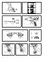
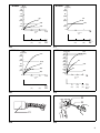
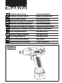
GB Cordless Impact Driver Instruction Manual F Tournevis à chocs sans fil Manuel d’instructions D Akku-Schlagschrauber Betriebsanleitung I Avvitatrice ad impulso a batteria Istruzioni per l’uso NL Snoerloze slagschroevedraaier Gebruiksaanwijzing E Atornillador de impacto a batería P Parafusadora de impacto a bateria Manual de instruções DK Akku slagskruetrækker Manual de instrucciones Brugsanvisning S Sladdlös slagskruvdragare Bruksanvisning N Accu slagboremaskin Bruksanvisning SF Iskevä akkuruuvinväännin Käyttöohje GR Φορητ κρουστικ κατσαβίδι Οδηγίες χρήσεως BTD042 BTD062 3 (C) E F orange 3 E 1 F orange 2 5 6 7 3 4 8 8 (C) 9 E 10 11 12 5 6 3 13 16 7 14 15 1 7 2 4 80% - 100% 60% - 80% 40% - 60% 10% - 40% 0% - 10% 2 1 4 80% - 100% 60% - 80% 40% - 60% 10% - 40% 0% - 10% 8 9 E F F BTD042 BTD042 Nm (kgf cm) Nm (kgf cm) 40 (408) 40 (408) 30 (306) 30 (306) M8 20 (204) M6 20 (204) (M8) 10 (102) (M6) 10 (102) M6 (M6) 0 0.5 1.0 *2 17 25 50 (13) (25) 1.0 18 17 *2 19 20 10 BTD062 0 18 50 100 (25) (50) 19 20*1 11 Nm BTD062 (kgf cm) Nm (kgf cm) 50 (510) 30 (306) 20 (204) 10 (102) 0 M10 (M10) 60 (612) M10 40 (408) (M10) 40 (408) M8 30 (306) (M8) 20 (204) (M6) 10 (102) M6 0 M8 (M8) M6 (M6) 1.0 18 1.0 25 50 50 100 150 (13) (25) 19 20 (25) (50) (75) 0.5 *2 17 12 2.0 3.0 17 *2 18 19 20*1 13 22 23 21 14 15 3 ENGLISH Explanation of general view 1 2 3 4 5 6 7 8 Battery cartridge Button Indicator lamp Capacity Bit Sleeve Switch trigger Reversing switch lever 9 10 11 12 13 14 15 16 A side B side Clockwise Counterclockwise ON Tool housing Screwdriver OFF 17 18 19 20 21 22 23 Fastening time Seconds Number of impacts (Presetting number) Limit mark Brush holder cap Screwdriver SPECIFICATIONS Model BTD042 Capacities Machine screw ........................................................................................ M4 – M8 Standard bolt ........................................................................................... M5 – M10 High tensile bolt....................................................................................... M5 – M8 No load speed (min–1)................................................................................ 0 – 2,500 Impacts per minute..................................................................................... 0 – 3,500 Overall length ............................................................................................. 164 mm Net weight .................................................................................................. 1.0 kg Rated voltage ............................................................................................. D.C. 9.6 V • Due to our continuing program of research and development, the specifications herein are subject to change without notice. • Note: Specifications may differ from country to country. Safety hints For your own safety, please refer to the enclosed safety instructions. 7. 8. ENC005-1 2. 3. 4. 5. 6. 4 Do not incinerate the battery cartridge even if it is severely damaged or is completely worn out. The battery cartridge can explode in a fire. Be careful not to drop or strike battery. Tips for maintaining maximum battery life 1. Before using battery cartridge, read all instructions and cautionary markings on (1) battery charger, (2) battery, and (3) product using battery. Do not disassemble battery cartridge. If operating time has become excessively shorter, stop operating immediately. It may result in a risk of overheating, possible burns and even an explosion. If electrolyte gets into your eyes, rinse them out with clear water and seek medical attention right away. It may result in loss of your eyesight. Do not short the battery cartridge: (1) Do not touch the terminals with any conductive material. (2) Avoid storing battery cartridge in a container with other metal objects such as nails, coins, etc. (3) Do not expose battery cartridge to water or rain. A battery short can cause a large current flow, overheating, possible burns and even a breakdown. Do not store the tool and battery cartridge in locations where the temperature may reach or exceed 50°C (122°F). M4 – M8 M5 – M12 M5 – M10 0 – 2,500 0 – 3,000 164 mm 1.0 kg D.C. 9.6 V SAVE THESE INSTRUCTIONS. IMPORTANT SAFETY INSTRUCTIONS FOR BATTERY CARTRIDGE 1. BTD062 2. 3. 4. Charge the battery cartridge before completely discharged. Always stop tool operation and charge the battery cartridge when you notice less tool power. Never recharge a fully charged battery cartridge. Overcharging shortens the battery service life. Charge the battery cartridge with room temperature at 10°C – 40°C (50°F – 104°F). Let a hot battery cartridge cool down before charging it. Charge the Nickel Metal Hydride battery cartridge when you do not use it for more than six months. ADDITIONAL SAFETY RULES FOR TOOL ENB024-1 1. 2. 3. 4. 5. Be aware that this tool is always in an operating condition, because it does not have to be plugged into an electrical outlet. Hold tool by insulated gripping surfaces when performing an operation where the cutting tool may contact hidden wiring. Contact with a “live” wire will make exposed metal parts of the tool “live” and shock the operator. Always be sure you have a firm footing. Be sure no one is below when using the tool in high locations. Hold the tool firmly. Wear ear protectors. SAVE THESE INSTRUCTIONS. OPERATING INSTRUCTIONS Installing or removing battery cartridge (Fig.1) • To remove the battery cartridge, withdraw it from the tool while pressing the buttons on both sides of the cartridge. • To insert the battery cartridge, align the tongue on the battery cartridge with the groove in the housing and slip it into place. Always insert it all the way until it locks in place with a little click. If not, it may accidentally fall out of the tool, causing injury to you or someone around you. • Do not use force when inserting the battery cartridge. If the cartridge does not slide in easily, it is not being inserted correctly. Checking the remaining battery capacity (Fig. 2) When charging When the charging begins, the first (far left) indicator lamp begins to flicker. Then, as charging proceeds, the other lamps light, one after the other, to indicate the battery capacity. When using When the tool is switched on, the lamps will light to indicate the remaining battery capacity. When the tool is switched off, the light goes out automatically. If the battery has not been used for a long time, or is needed refresh charging, the orange lamp begins to flicker. Use Makita refreshing adapter to refresh the battery. CAUTION: A battery cartridge extracted from the charger that has been unplugged with the battery cartridge inserted does not work even if it is inserted in the tool. At this time, recharge it for about five seconds before use. Installing or removing bit (Fig. 3) CAUTION: Always be sure that the tool is switched off and the battery cartridge is removed before installing or removing the bit. Use only the driver bit or socket bit shown in the figure below. Do not use any other driver bit or socket bit. 12 mm 9 mm To install the bit, pull the sleeve in the direction of the arrow and insert the bit into the sleeve as far as it will go. Then release the sleeve to secure the bit. To remove the bit, pull the sleeve in the direction of the arrow and pull the bit out firmly. NOTE: If the bit is not inserted deep enough into the sleeve, the sleeve will not return to its original position and the bit will not be secured. In this case, try re-inserting the bit according to the instructions above. Switch action (Fig. 4) CAUTION: Before inserting the battery cartridge into the tool, always check to see that the switch trigger actuates properly and returns to the “OFF” position when released. To start the tool, simply pull the trigger. Tool speed is increased by increasing pressure on the trigger. Release the trigger to stop. Reversing switch action (Fig. 5) CAUTION: • Always check the direction of rotation before operation. • Use the reversing switch only after the tool comes to a complete stop. Changing the direction of rotation before the tool stops may damage the tool. • When not operating the tool, always set the reversing switch lever to the neutral position. This tool has a reversing switch to change the direction of rotation. Depress the reversing switch lever from the A side for clockwise rotation or from the B side for counterclockwise rotation. When the reversing switch lever is in the neutral position, the switch trigger cannot be pulled. Auto-stop mechanism (Fig. 6) The tool stops automatically after the battery capacity reaches under 20% to prevent the lack of fastening torque. (Red color lamp lights on.) Charge the battery or use a new fully charged one. Auto-stop setting for number of impacts This tool has a convenient auto-stop mechanism that allows you to preset the desired number of impacts in terms of the application. The tool then stops automatically after reaching the preset number of impacts. 1. Pulling the trigger, insert the battery cartridge. Keep on pulling the trigger after inserting the battery cartridge. (The indicating lamp on the back of the tool will flash about 10 times, then the lamp will keep lighting up lit.) (Fig. 7) 2. Hit the tool housing around the grip once with a screwdriver etc. (The indicating lamp will go out.) (Fig. 8) 3. Release the trigger. (The indicating lamp will keep lighting up lit for 0.5 seconds, then the lamp will go out.) (Fig. 9) 4. Hit the tool housing preset number of first digit except 0. (The indicating lamp will light up in green color. Then, the light goes out. ) Example: When the preset number is 12, hit the tool housing once. 5. Pull the trigger, then release it. 6. Hit the tool housing preset number of second digit except 0. (The indicating lamp will light up in red color. Then, the light goes out.) Example: When the preset number is 12, hit the tool housing two times. 7. Pull the trigger, then release the trigger. (The indicating lamp will light up.) 8. Remove the battery cartridge. (Presetting has finished.) (The indicating lamp will go out.) CAUTION: When you change the presetting, do the same procedure as above 1 – 8. 5 Confirming the presetting Switch off the tool and insert the battery cartridge. The indicating lamp will indicate the presetting number. Green lamp shows the first digit. Red lamp shows the second digit. Example: Presetting number is 12. Green color lamp flashes once. Red color lamp flashes two times. The lamp goes out. Relation between presetting number and action Presetting number Clockwise rotation Counterclockwise rotation 00 Auto-stop setting does not work. Auto-stop setting does not work. 01 – 99 After impacting [number of impacts (presetting number x 2) x 0.02] seconds Green color lamp lights on. Switch off before impacting [number of impacts (presetting number x 2) x 0.02] seconds Red color lamp lights on. Then, the lamp will go out. Indicating lamp • After impacting preset numbers, the indicating lamp lights in green color. • The red color light will light on if the trigger is pulled before the presetting number of impacts is achieved. It indicates that the operation is incomplete. Operation (Fig. 10, 11, 12 & 13) [*1] Presetting number of impacts is impossible for more than 200 impacts (4 seconds). [*2] Fastening time includes when you pull the trigger completely. The proper fastening torque may differ depending upon the kind or size of the screw/bolt, the material of the workpiece to be fastened, etc. The relation between fastening torque and fastening time is shown in Fig. 10 & 12 for standard bolt or Fig. 11 & 13 for high tensile bolt. Hold the tool firmly and place the point of the driver bit in the screw head. Apply forward pressure to the tool to the extent that the bit will not slip off the screw and turn the tool on to start operation. NOTE: • Hold the tool pointed straight at the screw. • If you tighten the screw for a time longer than shown in the figures, the screw or the point of the driver bit may be overstressed, stripped, damaged, etc. Before starting your job, always perform a test operation to determine the proper fastening time for your screw. • If the tool is operated continuously, allow the tool to rest for 15 minutes before proceeding with a fresh battery. The fastening torque is affected by a wide variety of factors including the following. After fastening, always check the torque with a torque wrench. 1. When the battery cartridge is discharged almost completely, voltage will drop and the fastening torque will be reduced. 2. Driver bit or socket bit Failure to use the correct size driver bit or socket bit will cause a reduction in the fastening torque. 3. Bolt • Even though the torque coefficient and the class of bolt are the same, the proper fastening torque will differ according to the diameter of bolt. • Even though the diameters of bolts are the same, the proper fastening torque will differ according to 6 4. 5. Auto-stop setting does not work. Indication lamp goes out. the torque coefficient, the class of bolt and the bolt length. The manner of holding the tool or the material of driving position to be fastened will affect the torque. Operating the tool at low speed will cause a reduction in the fastening torque. MAINTENANCE CAUTION: Always be sure that the tool is switched off and the battery cartridge is removed before carrying out any work on the tool. Replacement of carbon brushes (Fig. 14 & 15) Replace carbon brushes when they are worn down to the limit mark. Both identical carbon brushes should be replaced at the same time. To maintain product safety and reliability, repairs, maintenance or adjustment should be carried out by a Makita Authorized Service Center. ACCESSORIES CAUTION: • These accessories or attachments are recommended for use with your Makita tool specified in this manual. The use of any other accessories or attachments might present a risk of injury to persons. Only use accessory or attachment for its stated purpose. If you need any assistance for more details regarding these accessories, ask your local Makita service center. • • • • Bit-piece Protector (clear, red, blue) Various type of Makita genuine batteries and chargers Automatic refreshing adapter NEDERLANDS Verklaring van algemene gegevens 1 2 3 4 5 6 7 8 Accu Knop Indicatielampje Accuvermogen Boor Bus Trekschakelaar Omkeerschakelaar 9 10 11 12 13 14 15 16 Kant A Kant B Rechtsom Linksom AAN (ON) Gereedschapshuis Schroevendraaier UIT (OFF) 17 18 19 20 21 22 23 Vastdraaitijd Seconden Aantal slagen (Vooraf ingesteld getal) Limietstreep Borstelhouderdop Schroevendraaier TECHNISCHE GEGEVENS Model BTD042 Capaciteit Machineschroef ...................................................................................... M4 – M8 Standaardbout ........................................................................................ M5 – M10 Bout met hoge trekvastheid .................................................................... M5 – M8 Toerental onbelast/min. (min-1) .................................................................. 0 – 2 500 Aantal slagen/min. ..................................................................................... 0 – 3 500 Totale lengte .............................................................................................. 164 mm Netto gewicht ............................................................................................. 1,0 kg Nominale spanning .................................................................................... DC 9,6 V • In verband met ononderbroken research en ontwikkeling behouden wij ons het recht voor bovenstaande technische gegevens te wijzigen zonder voorafgaande kennisgeving. • Opmerking: De technische gegevens kunnen van land tot land verschillen. Veiligheidswenken Voor uw veiligheid dient u de bijgevoegde Veiligheidsvoorschriften nauwkeurig op te volgen. BELANGRIJKE VEILIGHEIDSVOORSCHRIFTEN VOOR ACCU 1. 2. 3. 4. 5. 6. Lees alle voorschriften en waarschuwingen op (1) de acculader, (2) de accu, en (3) het product waarvoor de accu wordt gebruikt, aandachtig door alvorens de acculader in gebruik te nemen. Neem de accu niet uit elkaar. Als de gebruikstijd van een opgeladen accu aanzienlijk korter is geworden, moet u het gebruik ervan onmiddellijk stopzetten. Voortgezet gebruik kan oververhitting, brandwonden en zelfs een ontploffing veroorzaken. Als er elektrolyt in uw ogen is terechtgekomen, spoel dan uw ogen met schoon water en roep onmiddellijk de hulp van een dokter in. Elektrolyt in de ogen kan blindheid veroorzaken. Voorkom kortsluiting van de accu: (1) Raak de accuklemmen nooit aan met een geleidend materiaal. (2) Bewaar de accu niet in een bak waarin andere metalen voorwerpen zoals spijkers, munten e.d. worden bewaard. (3) Stel de accu niet bloot aan water of regen. Kortsluiting van de accu kan oorzaak zijn van een grote stroomafgifte, oververhitting, brandwonden, en zelfs defecten. Bewaar het gereedschap en de accu niet op plaatsen waar de temperatuur kan oplopen tot 50°C of hoger. 7. 8. BTD062 M4 – M8 M5 – M12 M5 – M10 0 – 2 500 0 – 3 000 164 mm 1,0 kg DC 9,6 V Werp de accu nooit in het vuur, ook niet wanneer hij zwaar beschadigd of volledig versleten is. De accu kan namelijk ontploffen in het vuur. Wees voorzichtig dat u de accu niet laat vallen en hem niet blootstelt aan schokken of stoten. BEWAAR DEZE VOORSCHRIFTEN. Tips voor een maximale levensduur van de accu 1. 2. 3. 4. Laad de accu op voordat hij volledig ontladen is. Stop het gebruik van het gereedschap en laad de accu op telkens wanneer u vaststelt dat het vermogen van het gereedschap is afgenomen. Laad een volledig opgeladen accu nooit opnieuw op. Als u de accu te veel oplaadt, zal hij minder lang meegaan. Laad de accu op bij een kamertemperatuur tussen 10°C en 40°C. Laat een warme accu afkoelen alvorens hem op te laden. Laad de nikkel-metaalhydride accu op telkens wanneer u hem langer dan zes maanden niet hebt gebruikt. AANVULLENDE VEILIGHEIDSVOORSCHRIFTEN VOOR HET GEREEDSCHAP 1. 2. 3. Denk eraan dat dit gereedschap altijd gebruiksklaar is, omdat het niet op een stopcontact hoeft te worden aangesloten. Houd het gereedschap bij de geïsoleerde handgrepen vast wanneer u boort op plaatsen waar het gereedschap met verborgen elektrische bedrading in aanraking kan komen. Door contact met een onder spanning staande draad, zullen ook de niet-geïsoleerde metalen delen van het gereedschap onder spanning komen te staan en zal de gebruiker een elektrische schok krijgen. Zorg ervoor dat u stevig staat op een vast ondergrond. Bij gebruik van het gereedschap op een hoge plaats dient u ervoor te zorgen dat niemand beneden u aanwezig is. 19 4. 5. Houd het gereedschap stevig vast. Draag oorbeschermers. BEWAAR DEZE VOORSCHRIFTEN. BEDIENINGSVOORSCHRIFTEN Installeren of verwijderen van de accu (Fig. 1) • Om de accu te verwijderen, neemt u deze uit het gereedschap terwijl u de knoppen aan beide zijden van de accu indrukt. • Om de accu te installeren, past u de rug op de accu in de groef in de behuizing van het gereedschap, en dan schuift u de accu naar binnen. Schuif de accu zo ver mogelijk erin, totdat deze met een klikgeluid vergrendelt. Indien u dit niet doet, kan de accu per ongeluk uit het gereedschap vallen en uzelf of anderen verwonden. • Als de accu moeilijk in de houder gaat, moet u niet proberen hem met geweld erin te duwen. Indien de accu er niet gemakkelijk ingaat, betekent dit dat u hem niet op de juiste wijze erin steekt. Controleren van het resterende accuvermogen (Fig. 2) Tijdens het laden Wanneer het laden begint, zal het eerste indicatielampje (uiterst links) beginnen te flikkeren. Naarmate het laden wordt voortgezet, zullen de andere lampjes in volgorde gaan branden om het accuvermogen aan te geven. Tijdens het gebruik Wanneer u het gereedschap inschakelt, gaan de lampjes branden om het resterende accuvermogen aan te geven. Wanneer u het gereedschap uitschakelt, gaan de lampjes automatisch uit. Als de accu een lange tijd niet is gebruikt of opgefrist moet worden, beginnen de oranje lampjes te flikkeren. Gebruik een Makita opfrisadapter om de accu op te frissen. LET OP: Als u de stekker van de acculader uit het stopcontact trekt terwijl de accu nog in de lader zit, zal deze accu niet werken nadat u hem in het gereedschap hebt geïnstalleerd. In dat geval moet u de accu ongeveer vijf seconden opnieuw opladen voordat u hem gebruikt. Aanbrengen of verwijderen van de schroefbit (Fig. 3) LET OP: Controleer altijd of het gereedschap is uitgeschakeld en het batterijpak is verwijderd, alvorens de schroefbit aan te brengen of te verwijderen. Gebruik alleen de schroefbit of schroefdop die hieronder is afgebeeld. Gebruik geen andere schroefbit of schroefdop. 12 mm 9 mm Om de schroefbit aan te brengen, trek de bus in de richting van de pijl en steek dan de schroefbit zo ver mogelijk erin. Laat daarna de bus los om de schroefbit vast te zetten. Om de schroefbit/dop te verwijderen, trek de bus in de richting van de pijl en trek dan de schroefbit/dop eruit. 20 OPMERKING: Indien de schroefbit niet diep genoeg in de bus wordt gestoken, zal de bus niet naar zijn oorspronkelijke positie terugkeren en zal de schroefbit niet goed vastzitten. In dat geval dient u de schroefbit opnieuw erin te steken volgens de bovenstaande aanwijzingen. Werking van de trekschakelaar (Fig. 4) LET OP: Alvorens de accu in het gereedschap te plaatsen, moet u altijd controleren of de trekschakelaar juist werkt en bij het loslaten naar de “OFF” positie terugkeert. Om het gereedschap in te schakelen, drukt u gewoon de trekschakelaar in. Hoe dieper de trekschakelaar wordt ingedrukt, hoe sneller het gereedschap draait. Om het gereedschap uit te schakelen, de trekschakelaar loslaten. Werking van de omkeerschakelaar (Fig. 5) LET OP: • Controleer altijd de draairichting alvorens het gereedschap te gebruiken. • Verander de stand van de omkeerschakelaar alleen nadat het gereedschap volledig tot stilstand is gekomen. Indien u de draairichting verandert terwijl de boor nog draait, kan het gereedschap beschadigd raken. • Zet de omkeerschakelaar altijd in de neutrale stand wanneer het gereedschap niet wordt gebruikt. Dit gereedschap heeft een omkeerschakelaar voor het veranderen van de draairichting. Druk de omkeerschakelaar in vanaf zijde A voor rechtse draairichting, of vanaf zijde B voor linkse draairichting. Wanneer deze schakelaar in de neutrale stand staat, kan de trekschakelaar niet worden ingedrukt. Mechanisme voor automatisch stoppen (Fig. 6) Wanneer het accuvermogen minder dan 20% is geworden, stopt het gereedschap automatisch om inschroeven met een te klein draaimoment te voorkomen. (Het rode lampje gaat aan.) Laad de accu op of gebruik een nieuwe, volledig opgeladen accu. Automatische stop na een vooraf ingesteld aantal slagen Dit gereedschap heeft een handig automatisch stopmechanisme waarmee u het gewenste aantal slagen voor elke toepassing vooraf kunt instellen. Het gereedschap zal automatisch stoppen zodra het vooraf ingestelde aantal slagen is bereikt. 1. Druk de trekschakelaar in en bevestig de accu. Blijf drukken op de trekschakelaar nadat de accu is bevestigd. (Het indicatielampje op de achterkant van het gereedschap zal ongeveer 10 keer knipperen; daarna zal het lampje gestadig branden.) (Fig. 7) 2. Tik met een schroevendraaier e.d. eenmaal op het gereedschapshuis rond de handgreep. (Het indicatielampje zal uitgaan.) (Fig. 8) 3. Laat de trekschakelaar los. (Het indicatielampje zal 0,5 seconden lang branden en daarna uitgaan.) (Fig. 9) 4. Tik zoveel keer op het gereedschapshuis als het eerste cijfer (tiental) van het vooraf in te stellen getal, behalve 0. (Het indicatielampje zal groen branden en daarna uitgaan.) Voorbeeld: Tik eenmaal op het gereedschapshuis indien het vooraf in te stellen getal 12 is. 5. Druk de trekschakelaar in en laat hem vervolgens los. 6. Tik zoveel keer op het gereedschapshuis als het tweede cijfer (eenheden) van het vooraf in te stellen getal, behalve 0. (Het indicatielampje zal rood branden en vervolgens uitgaan.) Voorbeeld: Tik tweemaal op het gereedschapshuis indien het vooraf in te stellen getal 12 is. 7. Druk de trekschakelaar in en laat hem vervolgens los. (Het indicatielampje zal branden.) 8. Maak de accu los van het gereedschap. (De instelling is voltooid.) (Het indicatielampje zal uitgaan.) LET OP: Herhaal de procedure 1 – 8 wanneer u de instelling wilt veranderen. Controleren van de instelling Schakel het gereedschap uit en bevestig de accu. Het indicatielampje zal het vooraf ingestelde getal aangeven. Het groene lampje toont het eerste cijfer (tiental). Het rode lampje toont het tweede cijfer (eenheden). Voorbeeld: Vooraf ingesteld getal 12. Het groene lampje knippert eenmaal Het rode lampje knippert tweemaal Het lampje gaat uit. Betrekking tussen vooraf ingesteld getal en werking Vooraf ingesteld getal Rechtse draairichting Linkse draairichting 00 Het automatische stopmechanisme werkt niet. Het automatische stopmechanisme werkt niet. Het automatische stopmechanisme werkt niet. Het indicatielampje gaat uit. 01 – 99 Na verloop van het vooraf ingestelde aantal seconden [= aantal slagen (vooraf ingesteld getal x 2) x 0,02 seconden] Het groene lampje gaat branden. Uitschakelen voordat het vooraf ingestelde aantal seconden [= aantal slagen (vooraf ingesteld getal x 2) x 0,02 seconden] zijn verlopen Het rode lampje gaat branden en gaat vervolgens uit. Indicatielampje • Nadat het vooraf ingestelde aantal slagen is bereikt, zal het indicatielampje groen branden. • Het rode lampje zal branden indien de trekschakelaar wordt ingedrukt voordat het vooraf ingestelde aantal slagen is bereikt. Dit lampje geeft aan dat de werking niet voltooid is. Bediening (Fig. 10, 11, 12 en 13) [*1] U kunt niet vooraf instellen voor automatische stop na meer dan 200 slagen (langer dan 4 seconden). [*2] De aandraaitijd geldt voor wanneer de trekschakelaar volledig wordt ingedrukt. Het juiste aandraaikoppel kan verschillen afhankelijk van het soort en de maat van de schroef/bout, het materiaal van het te bevestigen werkstuk, enz. De verhouding tussen het aandraaikoppel en de vastdraaitijd is aangegeven in Fig. 10 en 12 voor de standaardbout, en in Fig. 11 en 13 voor de bout met hoge trekvastheid. Houd het gereedschap stevig vast en plaats de punt van de schroefbit in de schroefkop. Oefen zoveel kracht op het gereedschap uit als nodig is om de schroefbit op z’n plaats te houden. Schakel vervolgens het gereedschap in om de werkzaamheden te starten. OPMERKING: • Houd het gereedschap altijd haaks. • Wanneer u de in de figuren aangegeven vastdraaitijden overschrijdt, kan de schroef doldraaien of de schroefkop of de punt van de schroefbit beschadigd worden. Het verdient daarom aanbeveling eerst een proefje te nemen voor het vaststellen van de juiste vastdraaitijd. • Wanneer u het gereedschap doorlopend gebruikt, moet u het gereedschap 15 minuten laten rusten alvorens met een verse accu verder te werken. Het aandraaikoppel wordt beïnvloed door een groot aantal verschillende faktoren, waaronder de volgende. Kontroleer na het vastdraaien altijd het aandraaikoppel met een momentsleutel. 1. Wanneer het batterijpak bijna leeg is, neemt het voltage af en vermindert het aandraaikoppel. 2. Schroefbit of schroefdop Gebruikt u niet de juiste maat dan heeft een vermindering van de aandraaikoppel plaats. 3. Bout • In geval het koppelcoefficient overeenkomt met de boutklasse, hangt het juiste aandraaikoppel af van de boutdiameter. • In geval de boutdiameters gelijk zijn, hangt het juiste aandraaikoppel af van het koppelcoefficient, de boutklasse en de boutlengte. 4. De manier van vasthouden van het gereedschap en de positie waarin de schroef in het materiaal vastgedraaid wordt, beinvloeden het koppel. 5. Bij lagere toerentallen wordt ook het aandraaikoppel kleiner. ONDERHOUD LET OP: Controleer altijd of het gereedschap is uitgeschakeld en de accu is losgekoppeld vooraleer onderhoud uit te voeren aan het gereedschap. Vervangen van koolborstels (Fig. 14 en 15) Vervang de borstels wanneer ze tot aan de aangegeven limiet zijn afgesleten. Beide koolborstels dienen tegelijkertijd te worden vervangen. Opdat het gereedschap veilig en betrouwbaar blijft, dienen alle reparaties, onderhoud of afstellingen te worden uitgevoerd bij een erkend Makita service centrum. 21 ACCESSOIRES LET OP: • Deze accessoires of hulpstukken worden aanbevolen voor gebruik met het Makita gereedschap dat in deze gebruiksaanwijzing is beschreven. Bij gebruik van andere accessoires of hulpstukken bestaat er gevaar voor persoonlijke verwonding. Gebruik de accessoires of hulpstukken uitsluitend voor hun bestemde doel. Raadpleeg het dichtstbijzijnde Makita Servicecentrum voor verder advies of bijzonderheden omtrent deze accessoires. • • • • Inzetstuk Bescherming (doorzichtig, rood, blauw) Diverse types originele Makita accu’s en acculaders Automatische opfrisadapter 22