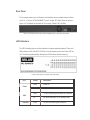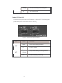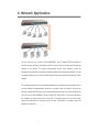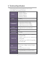
1
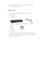
MIL-S24T2GPA
16 or 24-port 10/100/1000BASE- T
2 Combo SFP Slots
Unmanaged Switch
User Guide
Rev.A
09-MAY2006
Regulatory Approval
- FCC Class A
- UL 1950
- CSA C22.2 No. 950
- EN60950
- CE
- EN55022 Class A
- EN55024
Canadian EMI Notice
This Class A digital apparatus meets all the requirements of the Canadian Interference-Causing Equipment
Regulations.
Cet appareil numerique de la classe A respecte toutes les exigences du Reglement sur le materiel brouilleur du
Canada.
European Notice
Products with the CE Marking comply with both the EMC Directive (89/336/EEC) and the Low Voltage Directive
(73/23/EEC) issued by the Commission of the European Community Compliance with these directives imply
conformity to the following European Norms:
EN55022 (CISPR 22) - Radio Frequency Interference
EN61000-X - Electromagnetic Immunity
EN60950 (IEC950) - Product Safety
Five-Year Limited Warranty
MiLAN Technology warrants to the original consumer or purchaser that each of it's products,
and all components thereof, will be free from defects in material and/or workmanship for a
period of five years from the original factory shipment date. Any warranty hereunder is
extended to the original consumer or purchaser and is not assignable.
MiLAN Technology makes no express or implied warranties including, but not limited to, any
implied warranty of merchantability or fitness for a particular purpose, except as expressly set
forth in this warranty. In no event shall MiLAN Technology be liable for incidental or
consequential damages, costs, or expenses arising out of or in connection with the
performance of the product delivered hereunder. MiLAN Technology will in no case cover
damages arising out of the product being used in a negligent fashion or manner.
Trademarks
The MiLAN logo and MiLAN Technology trademarks are registered trademarks of MiLAN Technology in
the United States and/or other countries.
To Contact MiLAN Technology
For prompt response when calling for service information, have the following information ready:
- Product serial number and revision
- Date of purchase
- Vendor or place of purchase
You can reach MiLAN Technology technical support at:
E-mail: [email protected]
Telephone: +1.408.744.2751
Fax: +1.408.744.2771
MiLAN Technology
1329 Moffett Park Drive
Sunnyvale, CA 94089
United States of America
Telephone: +1.408.744.2775
Fax: +1.408.744.2793
http://www.milan.com
[email protected]
© Copyright 2004 MiLAN Technology
i
Content
1. Introduction........................................................ 1
Features ......................................................................................................1
Package Contents..........................................................................................2
2. Hardware Description .......................................... 3
Front Panel ..................................................................................................3
Rear Panel ...................................................................................................4
LED Indicators ..............................................................................................4
Combo SFP Slots LED.............................................................................5
3. Installation ......................................................... 6
4. Network Application ............................................ 7
5. Troubleshooting ................................................. 8
6. Technical Specification........................................ 9
ii
1. Introduction
The 16 or 24-port 10/100/1000BASE-T plus 2 combo SFP Slots Switch is an ideal solution
for solving traffic block at the core of the network. It offers 16 or 24 x auto-negotiating
10/100/1000Base-T Gigabit Ethernet ports that can significantly improve your network
backbone performance. This Switch will fit into any enterprise level network to act as an exit
to the backbone switch. It also provides 2 SFP Gigabit port for gigabit network connection.
The 16 or 24-port 10/100/1000BASE-T plus 2 Combo SFP Slots Switch features Auto
MDI/MDIX function for each port. [In general, MDI means connecting to another Hub or
Switch while MDIX means connecting to a workstation or PC. Therefore, Auto MDI/MDIX
means that you can connect to another Switch or workstation without changing
non-crossover or crossover cabling. The switch also features a store-and-forward switching
and can auto-learn and store source address on a 8K MAC address table.
Features
Compatible with IEEE 802.3 10Base-T, IEEE802.3u 100Base-TX, IEEE802.3z
gigabit fiber and IEEE802.3ab 1000Base-T
Backplain speeds of
32Gbps for 16-port
48Gbps for 24-port
16 or 24 ports gigabit switch with two COMBO SFP SLOTS
Automatic MDIX for all ports
8K entry MAC address table
10K Jumbo Frame support
500Kbits Memory buffer
IEEE802.3x flow control:
Pause frame for 10/100/1000Mbps full duplex
Backpressure for 10/100 Mbps half duplex
2 COMBO SFP SLOTS for SFP transceiver
Store-and-Forward architecture support
1
One DC fan for good ventilation and to increase system heat sink performance
19 inch Rack mount design
Package Contents
The 16 or 24-port 10/100/1000BASE-T plus 2 Combo SFP Slots Switch
Power Cord
Four Rubber Feet
User Manual
The 16 or 24-port 10/100/1000BASE-T plus 2 Combo SFP Slots Switch
User Guide
Power Cord
Rubber Feet
Figure 1-1. Package Contents
Compare the contents of your 16 or 24-port 10/100/1000BASE-T plus 2 Combo SFP Slots
Switch package with the standard checklist above. IF any item is missing or damaged,
please contact your local dealer for service.
2
2. Hardware Description
This Section describes the hardware of the 16 or 24-port 10/100/1000BASE-T plus 2
Combo SFP Slots Switch.
The physical dimensions of the 16 or 24-port 10/100/1000BASE-T plus 2 Combo SFP Slots
Switch is: 440 x 161 x 44 mm (W x D x H)
Front Panel
The Front Panel of the 16 or 24-port 10/100/1000BASE-T plus 2 Combo SFP Slots Switch
consists of 16 or 24 x auto-negotiation 10/100/1000Mbps Ethernet RJ-45 connectors
(support Automatic MDI/MDIX function), two Combo SFP Slots slot, and LED-indicators
(100/1000, Link/Activity, Full duplex/Collision) for each Gigabit port and power
LED-indicator for unit.
Figure 2-1. The Front Panel of the 24-port 10/100/1000BASE-T plus 2 Combo SFP Slots Switch
RJ-45 Ports (Auto MDI/MDIX): 16 or 24 x auto-negotiation 10/100/1000 Mbps
Ethernet RJ-45 connectors
[Auto MDI/MDIX means that you can connect to another switch or workstation without
changing straight through or crossover cabling.]
Combo SFP Slots ports: It is port 15 and 16 or 23 and 24. They support 3.3V SFP
Pluggables. It auto detects between Giga copper and Combo SFP Slots. Combo SFP
Slots module is optional. There are 2 LED indicators for Combo SFP Slots port – LNK
and ACT. When the Combo SFP Slots module is not installed, the port 15 and 16 or
23 and 24 remain as the 10/100/1000 copper only.
[Note] When the Combo SFP Slots module is installed, Combo SFP Slots have a default
priority over 10/100/1000 copper port. It doesn’t matter whether copper port has a valid link.
When SFP is in the slot copper ports are disabled.
3
Rear Panel
The 3-pronged power plug, on/off switch, and Ventilation fan are located at the rear Panel
of the 16 or 24-port 10/100/1000BASE-T plus 2 Combo SFP Slots Switch as shown in
Figure 2-2. The Switch will work with AC in the range 100-240V AC, 50-60Hz.
Figure 2-2. Rear panel of the 24-port 10/100/1000BASE-T plus 2 Combo SFP Slots Switch
LED Indicators
The LED Indicators gives a real-time indication of system operating statuses. There are 3
LED-indicators (1000, LNK/ACT, FDX/COL) for each Gigabit port and one Power LED for
unit. The following table provides descriptions of LEDs status and their meaning.
Figure 2-3.LED Indicators example of MIL-S24T2GPA
LED
Status
Description
Green
Power On
Off
Power is not connected
Green
The port is operating at the speed of 1000Mbps.
Off
No device attached or in 10/100Mbps mode
Green
The port is connecting with the device.
Power
1000
LNK/ACT
4
Blinking
The port is receiving or transmitting data.
Off
No device attached.
Table 2-1. The Descriptions of LED Indicators
Combo SFP Slots LED
2 Combo SFP Slots ports have two LED indicators – LNK and ACT. The following table
provides descriptions of LEDs status and their meaning.
Figure 2-4. Combo SFP Slots port LED Indicators
LED
Status
Description
Green
The port is connecting with device.
Off
No device attached.
LNK
Green
ACT
(Blinking)
Off
The port is transmitting or receiving the data.
No data transmitting or receiving.
Table 2-2. The Descriptions of Combo SFP Slots LED Indicators
5
3. Installation
This section shows the installation procedures of the switch.
Set the Switch on a sufficiently large flat space with a power outlet nearby. The surface
where you put your Switch should be clean, smooth, level, and sturdy. Make sure there is
enough clearance around the Switch to allow attachment of cables, power cord and air
circulation.
Attaching Rubber Feet
•
Make sure mounting surface on the bottom of the Switch is grease and dust free.
•
Remove adhesive backing from your Rubber Feet.
•
Apply the Rubber Feet to each corner on the bottom of the Switch. These footpads can
prevent the Switch from shock/vibration.
Power On
Connect the cord of power adapter to the power socket on the rear panel of the Switch. The
other side of power cord connects to the power outlet. Check the power indicator on the
front panel to see if power is properly supplied.
6
4. Network Application
You can use the 16 or 24-port 10/100/1000BASE-T plus 2 Combo SFP Slots Switch to
connect servers, switches, workstation, and PCs to each other by connecting these devices
directly to the Switch. The Switch automatically learns node address, which are
subsequently used to filter and forward all traffic based on the destination address. You can
use Gigabit fiber port to connect with fiber network that extend the Ethernet network to fiber
network.
For enterprise networks where large data broadcast are constantly processed, this switch is
an ideal suitable for departmental switches to connect to the Core Switch. All ports can
connect to departmental switches, and the departmental switches can be connected to the
16 or 24-port 10/100/1000BASE-T plus 2 Combo SFP Slots Switch. Then all the devices in
this network can communicate with each other. Connecting servers to the Core Switch
allow each end station to access the server’s data. This switch is an ideal solution for
backbone connectivity.
7
5. Troubleshooting
The Switch can be easily monitored through panel indicators to assist in identifying
problems. This section describes common problems you may encounter and where you
can find possible solutions.
Diagnosing LED Indicator
If Link indicator does not light up after connection, you may check whether network
interface (e.g., a network adapter card on the attached device), network cable, or switch
port is defective or not. Verify that the switch and attached device are power on. Be sure the
cable is plugged into both the switch and corresponding device. Verified the proper cable
type is used and its length does not exceed specified limits.
Power
IF the power indicator does turn on when the power cord is plugged in, you may have a
problem with power outlet, or power cord. However, if the Switch powers off after running
for a while check for loose power connections, power losses or surges at power outlet. IF
you still cannot resolve the problem, contact your local dealer for assistance.
Transmission Mode
Verify that each port is set to the same transmission mode used by the attached device (i.e.,
half or full duplex). RJ-45 port uses auto-negotiation to set the transmission mode. If the
attached device operates at half duplex, the default when auto-negotiation fails, then it does
not have to support auto-negotiation.
Cabling
RJ-45 ports: Use unshielded twisted-pair (UTP) or shield twisted-pair (STP) cable for
RJ-45 connections: 100G Category 3,4 or 5 cable for 10Mbps connections or 100G
Category 5 cable for 100Mbps connections or 4-pair Category 5 copper cabling for
1000Mbps connection. Also be sure that the length of any twisted-pair connection does not
exceed 100 meters (328 feet).
8
6. Technical Specification
The following table provides the technical specification of the 16 or 24-port
10/100/1000BASE-T plus 2 Combo SFP Slots Switch.
IEEE802.3 10BASE-T
IEEE802.3u 100BASE-TX
Standard
IEEE802.3z Gigabit fiber
IEEE802.3ab 1000Base-T
Protocol
CSMA/CD
Technology
Store-and-Forward switching architecture
14880 Packets per Second for 10Mbps
Transfer Rate
148800 Packets per second for 100Mbps
1488000 Packets per second for 1000Mbps
RJ-45: 16 or 24 ports
Connector
COMBO SFP SLOTS: 2 x 3.3V SFP SLOTS
MAC Address
8K
Memory Buffer
500Kbytes
10BASE-T: 2 pairs UTP/STP CAT.3, 4, 5 cable EIA/TIA
568 100Ohm(100M)
100BASE-TX: 2 pairs UTP/STP CAT. 5 cable EIA/TIA 568
Network Cable
100Ohm(100M)
Gigabit Copper: 4 pairs UTP/STP CAT. 5 cable EIA/TIA
568 100Ohm(100M)
System: Power
Per RJ-45 port: 1000Mbps, Link/Activity, Full duplex/
LED
collision
Combo SFP Slots slot: Link, Activity
Power Supply
Internal power supply, AC 100~240VAC, 50/60 Hz
Power
26.5 Watts(maximum)
9
Consumption
Operation
0C to 45C (32F to 113F)
Temperature
Operation
10% to 90% (Non-condensing)
Humidity
Dimension
440mm(W) x 161mm(D) x 44mm (H)
EMI & Safety
FCC Class A, CE, UL, CE/EN60950
6475 City West Pkwy
Eden Prairie, MN 55344
Tel.: +1.952.941.7600
[email protected]
10