1
Warning This equipment generates and uses radio frequency energy. If it
is not installed and used properly, that is, in strict accordance
with the manufacturer's instructions, it may cause interference to
radio and television reception.
It has been tested and found to comply with the limits for a
Class B computing device in accordance with the specifications
in Subpart J, Part 15, of FCC Rules. These rules are designed
to provide reasonable protection against such interference in a
residential installation. However, there is no guarantee that
interference will not occur in a particular installation.
If this equipment does cause interference to radio or television
reception, which can be determined by turning the equipment
off and on, the user is encouraged to try to correct the
interference by one or more of the following measures:
* Reorient the receiving antenna
* Relocate the computer with respect to the receIver
* Move the computer away from the receiver
* Plug the computer into a different outlet so that computer
and receiver are on different branch circuits
If necessary, you should consult the dealer or an experienced. radio/television technician for additional suggestions. You may· find the following booklet prepared by the Federal Communica
tions Commission helpful: "How to Identify and Resolve Radio-TV Interference Problems" This booklet is available from the U.S. Government Printing Office, Washington, DC20402, Stock No. 004-000-00345-4. Warning: To ensure that the use of this product does not contribute to interference. It is necessary to use shielded I/O cables. 1
Copyright
This manual is copyrighted with all rights reserved. No portion
of this document may be copied or reproduced by any means
without the prior consent in writing from Video Technology
Computers, Inc.
While every precaution has been taken in the preparation of
this book, Video Technology assumes no. responsibility for errors
or omissions. Neither is any liability assumed for damages
resulting from the use of the information contained herein.
© Copyright 1988 by Video Technology Computers, Ltd.
IBM is a registered trademark of International Business
Machines Corp.
Hercules is a registered trademark of Hercules Computer
Technology.
Intel is a registered trademark of Intel Corporation.
MS-DOS is a registered trademark of Microsoft Corporation.
Lotus 1-2-3
Corporation.
IS
a registered trademark of Lotus Development
DBase III is a registered trademark of Ashton-Tate.
WordPerfect is a registered trademark of WordPerfect
Corporation.
2
Table of Contents Chapter 1: Installation ................................................................ 5 Introduction ....................................................................................
Preparing for the Installation ..................................................
Checking the Contents of the Package ..............................
Hardware Features Overview ..................................................
Connecting Peripherals ..............................................................
Starting the computer ................................................................
Setting the System Clock ........................................................
Operation Speed ..........................................................................
5
7
8
9
11 13 15 16 Chapter 2: Using the Keyboard .......................................... 17 The Keyboard Security Lock .................................................. 17 Overview ........................................................................................ 18 Typewriter Keys .......................................................................... 19 Nunleric Keypad .......................................................................... 22 Editing and Cursor Control Keys ........................................ 25 Function Keys .............................................................................. 27 Chapter 3: Introduction for New Users ........................ 29 Facts You Should Know ..........................................................
Introduction to MS-DOS ..........................................................
Storing Files on a Computer ................................................
Organizing Files into Directories ..........................................
The Menu of MS-DOS Activities ........................................
How to Care for Your Computer ......................................
Diskette Care .......... ....... ........................ .......... ..................... ......
3
29 30 31 32 34 38 39 Chapter 4: Enhancements .......................................................... 43 Special Note ..................................................................................
Opening the System Unit ........................................................
Road Map of Internal Components ....................................
Expanding System Memory to 640KB ................................
Installing Parity RAM ..............................................................
Installing Expansion Cards ......................................................
Installing an 8087 Math Co-Processor ................................
Installing Expanded Memory ..................................................
Using Expanded Memory ........................................................
Installing a Hard Disk Drive ................................................
43 44 45 47 51 54 56 58 60 62 Chapter 5: Troubleshooting Checklist .............................. 63 Symptoms and Suggestions ...................................................... 63 Beeps .............................................................................................. 65 Display Messages ........................................................................ 66 Chapter 6: Further Reading (Getting More Help) 67 Appendices: .......................................................................................... 69 Appendix 1: Dip Switches and Settings ..............................
Appendix 2: The Multi I/O Card ........................................
Appendix 3: The Monochrome Graphics/ Color Graphics Card ........................................
Appendix 4: Glossary of Computer Terms ........................
4
69 73 79 83 Chapter 1:
Installation
Introduction
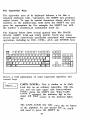
The computer is a high performance, expandable personal com
puter system which is designed specifically to be compatible
.with software and peripherals conforming to the popular MS
DOS and mM PC-XT standard.
In some versions of the computer there may be differences in
memory size and expansion cards installed, you may need to
refer to a separate user's manual for any other expansion card
installed.
• IBM PC/XT compatible processor running at 4.77 or 10
MHz.
• 512K memory, expandable to 1664K.
• 150 watt power supply.
• Two 5.25" 360K floppy drives, (some versions come with
one 5.25" 360K and one 3.5" 720K floppy drive), additional
space for one half-height hard disk drive.
• Some versions of computer have hard disk installed.
• 102 key enhanced keyboard.
• Multi I/O Card supporting Centronics parallel printer
interface, RS232 serial interface, and game port for a
joystick.
• Monochrome Graphics/Color Graphics Card, supporting
RGB, Hercules ,and composite monitors. Some versions
of computer will have EGA card installed, which supports
EGA, RGB, Hercules and composite monitors.
5
• Socket for an Intel 8087 math co-processor
• Eight expansion slots
In this fIrst chapter, we will guide you through the installation
of the computer, and introduce you to the basic structure of
the computer. If you are unfamiliar with the meaning of a cer
tain term, you can consult the glossary in Appendix 4 for a
definition.
6
Preparing for the Installation
Before you install the computer, you should have a large clear
area on which to work. Clear a tabletop large enough to hold
the system unit and keyboard. The monitor can sit on top of
the system unit if space is at a premium. You will need the
following:
• A grounded, three-prong power outlet
• A small flathead screwdriver
These tools are sufficient for a normal installation. If you need
to open up the system unit to install additional memory, disk
drives, or expansion cards, you'll also need the following:
• A small Philips screwdriver
• A cup or an ashtray to hold loose screws
7
Checking the Contents of the Package
Carefully unpack the computer from its carton. Make sure the
carton contains the following:
• The computer system unit
• A keyboard
• A power cord
• A video cable for composite monitors
• A package with manuals for MS-DOS®and GW/BASIC ®(optional)
• A package containing four diskettes
• A warranty card
It is important to save the carton and packing materials in
case you need to ship your unit in the future. Be sure to
return the warranty card as soon as possible.
8
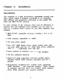
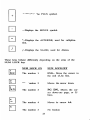
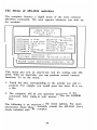
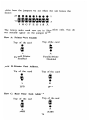
Hardware Features Overview
With the computer on a level surface, examine the following
features on the front panel:
Keyboard lock/unlock LED indicators
"B"
Space reserved for hard
When the security lock is switched at left position, keyboard is
unlocked and reset button is enabled; with the lock switched at
right position, keyboard is locked and reset button is disabled.
The speed indicator is used to indicate the operation speed of
the computer, a "5" will be displayed when computer operates
at normal speed (4.77MHz) and a "10" will be displayed when
the computer operates at high speed (10 MHz).
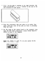
Notice the latch on each of the disk drives. With the latch in
the horizontal position (pointing to the right), the drive is open,
and ready to receive a diskette. After inserting a diskette, close
the drive by turning the latch clockwise so it's pointing down
wards.
9
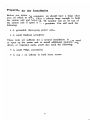
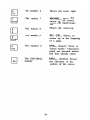
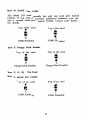
Diskette are
On the right side panel, you'll find the ON-OFF switch. The
"1" setting means "ON", and "0" means "OFF".
On the back side, there are several important connectors. You
should notice:
Monochrome monitor
EGA card
DIP switch
eGA, monochrome or
EGA monitor
Toggle switch
For composite monochrome monitor
Monochrome graphics/Color graphiCS
card
In normal installations, there is no need to open the
system cabinet. If you will be adding enhancements, see
Chapter 4 for instructions on opening the system unit.
10
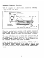
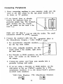
Connecting Peripherals
1. Before connecting anything to your computer, make sure the
power is off. The switch on the right panel should be in
the down, or "0" position.
2. If you haven't done so already,
remove the keyboard from its
protective plastic bag. The keyboard
cable attaches into the rounded
five-pin socket on the back of the
main unit:
-r
~/ 0
Make sure the plug is lined up with the socket. The small
indentation should be pointing upwards.
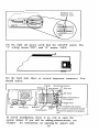
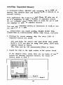
3. Connect the monitor's cable into the appropriate place on
the Monochrome Graphics / Color Graphics Card.
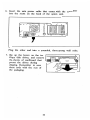
• For monochrome composite monitors, use the top round socket. • For color, composite monitors, use the round socket in the middle, right above the slide switch • For Hercules or RGB monitors, use the 9-pin "D" socket on the bottom of the adapter. 4. Connect the power cord from your monitor into a grounded, 3-prong wall outlet. 5. If you are using a Hercules or RGB monitor, set the
slide switch to the up ("MDA") position for a TTL
monochrome monitors, or to the down ("CGA") position
for RGB color monitors.
RGB Color Monitors
TTL Monochrome Monitors
MDArnl
MDAril
CGAl!J
CGAl1!J
11
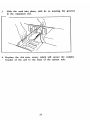
6. Insert the main power cable that comes with the computer
into the socket on the back of the system unit.
,
Plug the other end into a grounded, three-prong wall outlet.
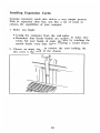
7. Flip up the levers on the two
floppy disk drives, and remove
the sheets of cardboard that
protect the drives during
shipping. Remember to save
these cards with the rest of
the packaging.
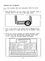
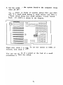
12 Starting the Computer
For system installed with hard disk, please follow the proce
dure:
1. Turn on the power to your monitor. The ON/OFF switch
IS
normally found on the front of the video. screen.
-
2. Turn on the power to the system unit by flipping the red
power switch on the right side into the up position, labeled
"1".
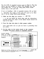
3. During the start-up procedure, the system performs a mem
ory test, then loads the MS-DOS operating system. After
several seconds, the following display will appear:
LASER TURBO XT Start Up Utility Main Menu [A]Format a disk
[B]Format a sys disk
[C]Format hard drive
[D)Copy file(s)
[E) Copy disk
[F]Make a directory
[G]Remove directory
i
II
[H]Change directory
[I]Display directory
[J]Run a program
[K)Change date &time
[L)Check config.
[M]Display help file
[N]Exit to DOS
Current directory: C: \ Current date/time: 05-01-88 09:35:51
©1988 Video Technology Computers,
13
~
Inc.
II
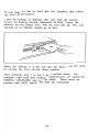
If your computer has no hard disk drive installed, then follow
the following procedures:
Open the package of diskettes that came with the system.
Locate the diskette labeled "Microsoft MS-DOS." Insert the
diskette into the floppy drive with the label side up. The oval
opening in the diskette should go in first.
When the diskette is all the way into the drive, close the latch
by moving the lever into the down position.
Then performs step 1 to step 3 as described above. For
_computer with hard disk installed, subdirectories are opened for
MSDOS, GW /BASIC and start up utility. These users can
practice with DOS, BASIC and start up commands.
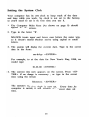
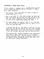
14 Setting the System Clock
Your computer has its own clock to keep track of the date
and time while you work. The clock is not set in the factory,
so you'll need to set it the first time you use it.
1. The Computer Main Menu (As shown on page 9) should
appear on the screen.
2. Type in the letter "K" .
MS-DOS treats upper and lower case letters the same way,
so it doesn't matter whether you're using capital or small
letters.
3. The system will display the current date. Type m the correct
date in the form:
mm-dd-yy <ENTER>
For example, to set the date for New Year's Day, 1988, you
would type:
01-01-88 <ENTER>
4. The current time now appears on the screen. Press <EN
TER> if no change is necessary , or type in the correct
time using the format:
hh:mm:ss < ENTER>
The system's real-time clock is now set. Every time the
computer is started, it will retrieve the correct date and
time.
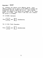
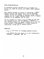
15 Operation Speed
The computer can operate at two different speeds. Some
software requires you to operate at 4.77 MHz to maintain full
compatibility with the original IBM PC-XT. When possible
though, you should try to operate your computer at the "turbo
speed" of 10 MHz. After warm or cold start, your computer
will operate at 4.77MHz.
For 4.77MHz Operation:
Press
~
and
I~ I
simultaneously.
For 10 MHz Turbo Operation:
Press
~
and
~
simultaneously.
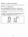
16 Chapter 2: Using the Keyboard
The Keyboard Security Lock
The computer features a keyboard lock on the front panel.
With the keyboard locked, no characters can be typed in to
the computer, protecting your system from unwanted intruders.
You receive two keys with the unit. Make sure you store one
in a safe place.
Two LEDs are used to indicate whether the keyboard is locked
or unlocked. For example, when the keyboard is locked, the
LED labelled with 'keyboard lock' will be on.
Lock ON
Indicator
Lock OFF
Indicator
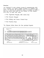
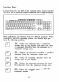
17 Overview
The keyboard is your primary means of communicating with
your computer. Its layout roughly resembles an ordinary type
writer. To describe the keyboard clearly, its helpful to divide it
into four parts, each with its own function. In this chapter,
we'll refer to these four areas:
• The Typewriter Keypad, with control keys
• The Numeric Keypad
• The Editing and Cursor Control keys
• The Function Keys
The diagram below shows the four principal keypads:
Typewriter keys
Editing & Cursor Control
18 Numeric
ke~pali
The Typewriter Keys
The typewriter area of the keyboard behaves a lot like a
standard keyboard. Like a typewriter, the SHIFT key produces
capital letters. To type the special characters shown above the
numbers on the number keys, hold down the SHIFT key and
press the appropriate key. For example, the SHIFT key with
the number 1 produces an exclamation mark (!).
The diagram below shows several general keys like BACK
SPACE, SHIFT, TAB, and CAPS LOCK You'll also notice
several special control keys specifically associated with computer
operations, including the ESC, CfRL, ALT, and ENTER keys.
Here's a brief explanation of some important typewriter and
control keys:
B
Caps Lock CAPS WCK... This is similar to the Sbift
Lock key on an ordinary typewriter. With this
key, you can type upper case letters without
holding down the SHIFT key. When CAPS
LOCK is engaged, the indicator light in the
upper left hand corner of the keyboard lights
up.
The CAPS LOCK key only affects the 26 letters
of the alphabet. To get special symbols, you'll
still need to press the SHIFT key.
19
ENTER... As a RETURN key, it ends the line
being typed and advances to the next line. As
the ENTER key, it's used to execute commands
you have typed.
10
SHIFf... For upper case letters, punctuation, or
Shift
symbols, either one of the two SHIFT keys can
be pressed. When the CAPS WCK key is
engaged, the SHIFT key acts as an "Un-Shift"
key, allowing you to type lower case letters.
EJ BACKSPACE... Like the Backspace key on a
typewriter, it will erase one character to the left
of the cursor.
TAB••• Like the Tab key on the typewriter, it
moves the cursor to the next tab top. Tab stops
occur every eight characters, unless otherwise
specified. Using SHIFT with TAB moves the
cursor backwards to the previous tab stop.
ESC... The ESCAPE key has different meanings
depending on the application you are using. In
the BASIC language, for example, ESC erases a
line from the screen.
CTRL... The CONTROL key does nothing on
its own. Like the SHIFT key, CTRL is used
only in conjunction with other keys. CTRL
performs many different functions depending on
the application you are using.
Here are some examples of how CTRL
in the MS-DOS operating system:
IS
used
CTRL-SCROLL LOCK...BREAK
This function stops your program while it is
running.
20
CTRL-PRINT SCREEN...ECHO
The computer prints each line as it is typed. To
cancel the function, press CTRL-Print SCREEN
again.
CTRL-NUM WCK. ...PAUSE
This temporarily halts printing or a screen
display. Press any key to continue.
CTRL-ALT-DEL.. ..sySTEM RESET
When these three keys are pressed together, the
system resets and reloads the operating system.
ALT... Like the CTRL key, ALT performs no
function on its own. It is used in conjunction
with other keys to perform special functions.
The meaning of ALT varies, depending on the
application you're using.
While using the BASIC language, the ALT key
allows you to quickly and easily enter BASIC
keywords with a single keystroke. For example,
ALT-I generates the word "INPUT". Here's a
table of ALT key combinations in BASIC:
A......... AUTO
B.......... BSAVE
c.......... COLOR
D ......... DELETE
E .......... ELSE
F .......... FOR
G ......... GOTO
H ......... HEX$
1........... INPUT
J ........... Undefined
K......... KEy
L.. ........ LOCATE
M ......... MOTOR N......... NEXT 0 ......... OPEN P .......... PRINT Q ......... Undefined R. ........ RUN S.......... SCREEN T .......... THEN U ......... USING V ......... VAL W........ WIDTH X ......... XOR 21 The Numeric Keypad
The numeric keypad, shown below, performs a dual function.
With the NUM LOCK key engaged (indicated by the status
light in the upper right and corner of the keyboard), the
keypad is useful for the rapid data entry of numbers. Without
NUM LOCK, the keypad can be used to move the cursor or
do special editing features.
The 102 key enhanced keyboard provides a separate keypad for
cursor control and editing (located immediately to the left of
the numeric keypad). For this reason, most users will find it
convenient to leave the NUM LOCK key on. This allows the
numeric keypad to be used for rapid entry of numbers.
These keys operate the same regardless of the status of the
NUM LOCK key:
ENTER... Works the same as the ENTER key
on the Typewriter Keypad.
Enter
22 +...Displays the PLUS symbol.
+
D
-...Displays the MINUS symbol.
• ...Displays the ASTERISK, used for multiplica
tion.
j ...Displays the SLASH, used for division.
These keys behave differently depending on the status of the
NUM LOCK key:
NUM LOCK ON
NUM LOCK OFF
The number 1
END... Moves the cursor to
the end of the line.
[]
The number 2
Moves the cursor down.
The number 3 PG DN... Moves the cur
sor down one page, or 25
lines.
The number 4 Moves the cursor left.
The number 5 No function
23
[g
The number 6
Moves the cursor right.
I~omel
The number 7
HOME... Moves the
[]
The number 8
Moves the cursor up.
I~upi
The number 9
PG UP... Moves the
I~ns I
The number 0
I~el I
cursor to the screen's
upper left hand corner.
cursor up to the beginning
of a page.
INS... (Insert) Turns on
"insert mode." Characters
typed are inserted before
text that already exists.
DEL••• (Delete) Erases
one character at the
position of the cursor.
The DECIMAL
POINT
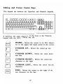
24 Editing and Cursor Control Keys
This keypad sits between the Typewriter and Numeric keypads.
It performs the same functions as the keys on the Numeric
keypad with the NUM LOCK key off:
6
H 0 ME... Moves the cursor to the first charac
ter in the upper left hand corner of the screen.
CURSOR UP... Moves the cursor up one
[!J [] CURSOR DOWN...
line.
Moves the cursor down
one line.
EJ CURSOR RIGHT ... Moves the cursor one
character to the right.
EJ CURSOR LEFr... Moves the cursor left one
EJ END... Moves the cursor to the right of the
character.
last character on the line.
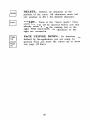
25 DELETE... Deletes one character at the
position of the cursor. All characters move left
one position to fill in the deleted character.
INSERT... Turns on the "insert mode." Char
acters you type will be inserted before text that
already exists, pushing the existing text to the
right. With insert mode off, characters to the
right are overwritten.
I I
I I
Page
Up
Page
On
PAGE UP/PAGE DOWN... Its functions arc
defined by the application you are using. In
general, these keys move the cursor up or down
one page (25 lines).
26
Function Keys
Located along the top half of the keyboard, these twelve function
keys allow you to perform complex commands with a single keystroke.
Most applications use function keys for different purposes. When
running the MS-DOS operating system, the function keys per
form the following activities:
FI... Copies one character from a temporary
storage area to the display. Each time you enter
a command, MS-DOS store the command in a
temporary storage area.
EJ
EJ
EJ
EJ
Fl... Displays all characters preceding a specified
character from the temporary storage area.
F3... Copies all remaining characters from the
storage area to the display.
F4 ... Deletes the characters preceding the speci
fied character from the temporary storage area.
F5 ... Enters the currently typed line into the
temporary storage area.
27
28
Chapter 3:
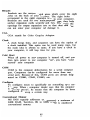
Introduction for New Users Facts You Should Know
This chapter is intended for people with no computing experi
ence. If you fall into this category, we hope you'll find some
of the concepts introduced here to be helpful. Let's start with
a few general facts:
• A computer is not like a television set that you can
simply take out of the box and plug in. It will require
both time and patience to learn. If you try to learn things
too quickly under pressure, you may get frustrated. We
recommend leaving plenty of time for learning.
• There is a fan on the back of the computer system unit.
This fan is absolutely essential for cooling the internal
components. Do not block this fan! Make sure you leave
plenty of space for air to circulate behind the computer.
• Static electricity can damage your system. Your body picks
up static electricity without you even knowing it, and even
a mild static shock can harm delicate computer compo
nents. To protect against static shock, always touch the
metal chassis of your system unit before touching other
electronics.
• Electrical interference and power surges can destroy com
puter components. Do not plug your computer into an
outlet that powers heavy equipment, like copiers or refrig
erators. If you live in a rural area with unreliable power,
you may want to purchase a surge suppressor to protect
your components from overload.
29 Introduction to MS-DOS
MS-DOS stands for MicroSoft Disk Operating System. An
operating system is a group of programs that acts as:
• A manager for your computer, monitor, and peripherals
• An interpreter, conveying your instructions to the computer
If you plan on running application programs only (software
written to perform specific tasks, e.g. Lotus 1-2-3®or WordPer
fect), you actually need to know very little about the MS-DOS
operating system. On the other hand, if you plan on wntmg
your own programs, you may have to learn quite a bit about
it.
We recommend learning enough about MS-DOS so you can
take advantages of all the features of your computer. We will
provide a basic introduction to MS-DOS in this booklet. To
find out more, you should consult the MS-DOS User's Guide
included with your system.
There are several excellent instruction manuals and tutorials
written about MS-DOS. Refer to Chapter 6 for a listing of
relevant books.
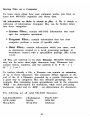
30 Storing Files on a Computer
To learn more about how your computer works, you have to
learn how MS-DOS organizes and stores data.
All information on disks is stored in fi1es. A fIle is simply a
collection of information. Computer fIles can be broken down
into three categories:
• System Files... contain MS-DOS information that man
ages the computer operations.
• Program Files... contain information that lets your
computer perform a series of specific tasks.
• Data Files... contain information which you enter, such
as documents created in a word processing package, or
worksheets created with a spreadsheet package (like Lotus
1-2-3).
All fIles are referred to by their filename. MS-DOS fIlenames
may not be more than eight characters long. Filenames can
contain letters, numbers, and the symbols $ & # % ' ( )
@
or !.
A
{
}
To further identify a file, a fIlename can contain an extension
of up to three characters. The extension always appears at the
end of the of a filename, preceded by a period. Extensions are
a good way to categorize fIles into efficient groupings. For
example, fIles containing Lotus spreadsheets end in the extension
.WKS - an abbreviation for worksheet, while word processing
documents could end in .DOC - an abbreviation for document.
The following are all valid MS-DOS filenames:
SALESLTR.DOC
QTR1.WKS
Menu.BAS
Checking.bal
MyFile
Work.TST
File#1.TXT
WlN.INI
XXX.xxx
31 Organizing Files into Directories
Files on a disk are grouped into directories. A directory is
simply a "Table of Contents" for the disk. For each file
residing on a disk, an entry is made in a directory recording
the name of the file, its size, and its location on the disk,
data of creation, attributes.
Every disk contains one main directory called the root directory.
The root directory serves as a "master index" for the disk.
When you format a new diskette for use on your computer,
the root directory is automatically created. When you start up
the computer, you are operating from the root directory.
The root directory can be subdivided into more directories for
the sake of organization. For example, all word processing
documents could be stored in a directory named "Letters".
Checkbook balances and your home budget could be grouped
into a directory named "Finance".
For many purposes, especially if you are using floppy disks
only, you may not need any additional directories. The root
directory alone should suffice. However, when you add a hard
disk, organizing your files into directories becomes essential
because the hard disk is capable of storing thousands of files.
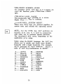
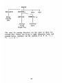
To summarize, the root directory can contain several subdirecto
ries, and each subdirectory in turn can contain other
subdirectories. In the illustration below, directory names appear
in boldface text, while file names appear in normal text:
32 ROOT
I
FINANCE
I
I
LETTERS
I
Budget
Checkbk
Bills
OFFICE
SlsDept
Acctg
Thank You
Filel
File2
PERSONAL
AuntMary
Janice
The rules for naming directories are the same as those for
naming fIles. Names can be up to eight characters long, and
contain letters, numbers, and the symbols $ & # % ' ( )
@
or 1.
A
{
}
33
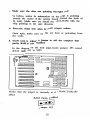
The Menu of MS-DOS Activities
The computer features a helpful menu of the most common
MS-DOS commands. The menu appears whenever you start up
the machine:
LASER TURBO XT
Start Up Utility
Main Menu
[A] Format a disk
[B] Format a sys disk
[C]Format hard drive
[D] Copy file (s)
[E] Copy disk
[F] Make a directory
[G]Remove directory
[H]Change directory
[I]Display directory
[J]Run a program
[K)Change date &time
[L]Check config.
[M]Display help file
[N] Exit to DOS
Current directory: c:\
Current date/time: 05-01-88 09:35:51
Il
©1988 Video Technology Corr,puters,
Inc
.11
This menu gives you an easy-to-use tool for working with MS
DOS. With one keystroke, you can perform several common
functions. To use the menu:
1. Touch the letter corresponding to the activity you wish to
perform. For example, you would press the letter D to copy
a file.
2. The computer will ask you questions pertaining to the
command. After typing in your answer, press the ENTER
key.
The following is an overview of the menu options. For more
information about these commands, consult the MS-DOS User's
Guide included with the computer.
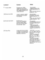
34 Command
Function
[A] Format a disk
Prepare a new, blank
diskette for use on your
system. You must have the
file FORMAT.EXE in the
current directory.
·Doyou have
FORMAT.EXE in the
current directory (Y or
N)?
'Enter the drive letter for
format (A: - D:)
[B] Format a sys disk
Creates a diskette capable
of being used as a system
start-up disk.
*Doyou have
FORMAT.EXE in the
current directory (Y or
N)?
'Enter the drive letter for
system format (A: - D:)
[C] Format hard drive
Prepares a hard disk for
use on the system. This
command should only be
done once, the first time
the hard disk is used.
*Doyou have
HARDFORMAT.BAT in
the current directory (Y
orN)?
'This command will
completely ERASE the
hard disk. Are you sure
you want to proceed? (Y
orN)
[D] Copy file(s)
Copies a file from one disk
to another or one directory
to another. Can also copy a
file within a directory.
'Enter the source drive
(A: - D:). This is the drive
where the file is located
currently.
'Enter the destination
drive (A: - D:). This is
where you want the new
file to go.
*Enter the file name to
copy. If you leave this
entry blank, the computer
will assume you want to
copy all files in the current
directory.
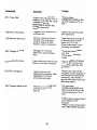
35 Command
Function
[E] Copy disk
Copies the contents of a
diskette in disk drive "A" to
a diskette in drive "B". You
must have the file
DISKCOPY.EXE in the
current directory.
·Doyou have
DISKCOPY.EXE in the
current directory ('l or
N)?
[F] Make a directory
Creates a new directory or
subdirectory.
·Enter the name for the
new directory.
[G] Remove directory
Deletes a directory from
the disk. The directory
must be empty of files
before it can be removed.
*The directory must have
ofiles for this to work.
Does it? ('l or N)
*Enter the name of the
directory to remove.
[H) Change directory
Changes the ·current
directory" to something
else.
·Enter the drive letter.
(A: -D:) ·Enter new directory name. [I] Display directory
Lists information about the
files in a certain directory.
·Enter qualifier (Default = *.•). If you leave this entry blank, all files will be listed. [J) Run a program
Used to start-up an
application program, like a
spreadsheet or word
processing package.
·Enter the name of the program. If the program is not located in the current directory, you'll need to specify the drive letter and directory name. [K] Change date & time
Used to set or change the
real-time clock in the
system.
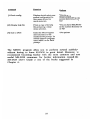
*Doyou have GErCLOCKEXE and SErCLOCK.EXE in the current directory ('l or N)? ·What is the current date? (Use MM-DD-YY format) ·What is the current time? (Use HH:MM:SS format) 36 Command
[L] Check config.
Displays details about your
system configuration (i.e.
how many drives, how
much memory).
*Doyou have
WHATAMI.EXE in the
current directory (Y or
N)?
[M] Display help me
Prints a copy of the help
file pertaining to these
menu selections.
in the current directory (Y
orN)?
[N] Exit to DOS
Ends this Menu Program
and returns you to the
standard DOS prompt. To
restart the menu program,
enter MENU at the DOS
prompt.
"Do you have HELPTXT
·No options
The MENU program allows you to perform several activities
without having to learn MS-DOS in great detail. However, we
recommend becoming familiar with the most common and most
useful MS-DOS commands. for further information consult the
MS-DOS User's Guide or one of the books suggested in
Chapter 6.
37 How to Care for Your Computer
1. Until you gain a great deal of experience, do not attempt
to probe the inside of your computer, particularly the power
supply. Dangerous levels of high voltage exist. Contact your
dealer for service if necessary.
2. Turn off the computer and unplug it from the wall before
you install anything inside the system unit, such as an ex
pansion card or memory chips. Failure to do so will result
in serious, irreparable damage to both the computer and the
add-on device.
3. Keep the computer away from excessive heat, humidity, dust,
or moisture.
4. Do not cover the fan or ventilation holes on the back panel
of the computer.
5. Do not use thinner, oil, or petroleum-based cleaners on the
cabinet or keyboard. Use only a damp cloth (with a mild
detergent, if necessary) for cleaning. Make sure the power is
off.
6. If you need to move your computer system, use the original
packaging to shield it from shock. If the system includes a
hard disk drive, you must run a special protection program
before moving. Refer to your hard disk manual for details.
7. Do not drop the main unit. Handle it with care.
8. Do not attempt to use your computer underwater.
38 Diskette Care
The 5-1/4" Floppy Disk Drive of the computer uses 5-1/4",
double sided, double density (40 tracks per inch), soft sectored
floppy diskettes. These diskettes are capable of holding 360K
(368,640 bytes).
Each floppy diskette has a write-protect notch on its side, as
shown in this diagram:
If this notch is covered, the computer will not let you write to
the diskette. This is a good way to make sure no one erases
diskettes that are absolutely crucial.
Always handle your floppy diskettes carefully. A small scratch,
stain, or even a speck of dust can destroy the information
stored on the diskette. The following guidelines will help pro
long the useful life of your diskettes and may help prevent the
loss of important data:
• Always keep diskettes m their protective envelope when not
in use.
• Never touch the diskette's shiny exposed surface.
• Don't bend diskettes.
• Keep diskettes away from magnetic fields (transformers,
motors, magnets, TVs, radios).
39 • Never lay a diskette on top of or next to the computer
system unit.
• Write only on a diskette label, and only with a soft felt
tip pen. Never use a ball point pen to write on diskettes.
• Keep diskettes out of direct sunlight and away from
excessive heat. They melt easily.
• Some versions of the computer has a 720K 3 1/2" Floppy
disk drive installed. These drives use 3 1/2" Floppy
diskettes: which are capable of holding 720K bytes maxi
mally.
40
Hints on using 3-1/2" drive
Before you are going to use the 3-1/2" drive, there are some
basic concept and terminology you need to know.
A physical drive is a drive that is physically connected to the
computer.
A logical drive is a drive that can be accessed through the
"drive letter" assigned, e.g. A:, B:.
Thus there may be more logical drives than physical drives,
since two or more logical drives may refer to the same physi
cal drive.
An external drive is the drive that is created by the" file
CONFIG.SYS. The drive letter for that external drive is speci
fied by assigning parameters on the CONFIG.SYS file. The
installation procedure of external drive is shown below.
Normally, after you have connected a 3.5" micro floppy disk
drive to your computer, you can access the drive as usual.
However, you will not be able to format a 3.5" diskette with
720KB storage capacity. This is expected because DOS presumes
your drive is a 360KB, 5.25" drive. To use your 3.5 inch floppy
disk drive as a 720KB drive, you should follow the procedures
below:
(A) If you are using DOS 3.2
1. Insert a DOS disk into drive A.
2. If your 3.5" disk drive is the second drive, create the
CONFIG.SYS file and include the following line:
drivparm = / d:1
Otherwise, change the parameter "d:1" to "d:O."
41 3. Warm boot the system.
3.5" disks can now be formatted on nOKB.
(B) If you are using DOS 3.3
1. Insert a DOS disk which contains the DRIVER.SYS into
drive A.
2. If your 3.5" disk drive is the second drive, create the
CONFIG.SYS file and include the follow line:
device
= driver.sys/d:l
This line tells the system to install an external drive C:.
The parameter /d:l specifies that the external drive C: is
logically linked to the second physical drive B:. That is to
say, you can access physical drive B: via logical drive C: in
addition to drive B:.
If your 3.5" disk drive
rameter "d:l" to "d:O."
IS
the first drive, change the pa
3. Warm boot the system.
The message "Loaded External Disk Driver for Drive Coo
will be displayed which indicates the external drive is suc
cessfully installed.
3.5" disks can now be formatted in nOKB via drive C: in the
3.5" disk drive. While drive C: is specifically created to allow
formatting in nOKB, normal disk access through drive B: (drive
A: for first drive) is still permitted, except that the disk can
only be formatted in 360KB, not nOKB.
New diskettes must be formatted before they can be used on
your computer. Refer to the "How to Format Your Disks"
section in the MS-DOS User's Guide.
42 Chapter 4: Enhancements
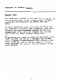
Special Note
The enhancements described in this chapter let you improve the
power and performance of your computer system. The parts
required for each enhancement are available from your
dealer.
All these enhancements require you to open the system unit
and install add-on accessories inside. Furthermore, some of the
instructions may seem complicated, especially for first time
computer users. If you are a new computer user, you ntay
want to have your dealer install the enhancements.
Before opening your system unit, make sure the power to your
computer is OFF, and the unit is unplugged from the wall
socket. Attempting to install expansion cards, memory, or other
internal components with the computer plugged in will cause
serious and irreparable damage to both the computer and the
add-on accessory.
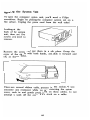
43 Opening the System Unit
To open the computer system unit, you'll need a Philips
screwdriver. Begin by placing the computer system unit on a
flat surface. Unplug the power cord from the wall outlet!
Looking at the
back of the system
unit, there are five
screws you need to
remove:
Remove the screws and put them in a safe place. Grasp the
cover of the chassis with both hands, and slide it forward and
off, as shown below.
There are several ribbon cables present in the system. If you
encounter any resistance while you are removing the system
cover, reach in and gently press down on these cables. Do not
attempt to yank off the cover if it's stuck on a cable.
44
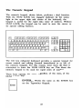
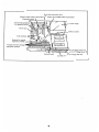
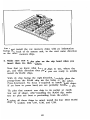
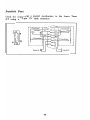
Road Map of Internal Components
With the system unit open, this is a good time to get a
general overview of the internal parts of the system unit:
Notice the following areas of the system unit:
• System Board
• Expansion Slots
• Hard Disk Controller
• Multiple Input-Output (I-O) Card
• EGA card
• Floppy Drives "A" and 5 1/4", 360K
• Floppy Drive "B" 3 1/2", nOK
• Socket for an 8087 Math Co-Processor
• Hard disk
"c"
• Power Supply
• Sockets for Memory Expansion to 640K.
• Ribbon Cables
• 4 Empty Rows for Installing Expanded Memory
• 2 DIP Switches
45 I lard disk controller card
Power supply
Sockets for memory expansion to 640K 4 empty rows for installing
e:.\panded memory
"'lIiiiijg~~U2~lli]
~~:::;~~~~9~~~~~~~~~
5-1/4" floppy drive "A"
or 5-1/4" floppy drive "B"
3-1/2" floppy disk "B"
liard disk "c"
46
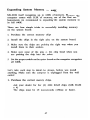
Expanding System Memory to 640K
MS-DOS itself recognizes up to 640K of memory. Because the
computer comes with 512K of memory, one of the fIrst en
hancements we recommend is expanding the system memory to
its full 640K.
There are four simple tricks to successfully installing memory
on the system board:
1. Purchase the correct memory chips.
2. Install the chips in the right place on the system board.
3. Make sure the chips are pointing the right way when you
install them in their sockets.
4. Make sure none of the pins on the chip bend when you
are pushing the chip into the socket.
5 Set the proper switch on the system board so the computer recognizes
all 640K.
Let's take each step in detail. As always, before you install
anything, Make sure the computer is unplugged from the wall
outlet!
1. Purchase the correct memory chips.
Ask your dealer for four (4) 4464 RAM chips (64K RAM x 4) The chips must be 150 nanoseconds (150ns) or faster. 47 2. Install the chips in the right sockets on the system board.
As shown in this
diagram, the sockets
for the four 4464
RAM chips are
highlighted. The chips
will be installed in
sockets U36, U37,
U38 and U39.
=c::J======
===
I
===I
c::J c::=::J ~ ~~6
====
====
====
====
====
6
CJc],
12:3=g§3
=-CJ=
u=
,=
=
c::::J
c::::J
-==
_==
-B§l
===.,
3. Make sure the chips are pointing the right way.
Take a careful look at the top of the memory chips. You'll
see a small indentation, notch, or marking at one end of
the chip.
Examine the two rows of memory chips currently installed in
the computer. Notice the indentation on the chips is pointing
towards the center of the system board (toward the back of
the unit).
48
You must install the new memory chips with the indentation
facing the back of the system unit, in the exact same direction
as the other memory chips.
4. Make sure none of the pins on the chip bend when you
insert them into their sockets.
Now that you know what kind of chips to use, where they
go, and which direction they point, you are ready to actually
install the RAM chips.
With the chip facing the right direction, carefully place the
prongs from the RAM chip into the holes on the socket.
Press downward. No force is required to install RAM chips.
If you have to press hard, you are probably bending a pin.
The pins that connect each chip to its socket' are easily
bent out of shape. After installing the RAM chip, make
sure no pins are bent or protruding from the socket.
Keeping all these things in mind, install the four 4464 RAM
chips in sockets U36, U37, U38, and U39.
49 5. Set the switch on the system board so the computer recog
nizes all 640K.
The computer has banks of switches labeled SW1 and SW2.
SWI is a bank switch having 8, small switches and SW2 is
a bank switch having four small switches. Locate Switch
Bank #1 (SW1) as shown in the diagram:
E~~~O
c:::::::J
~ c=::::J
c=::::J
Right now, switch 3 IS ON. To set your system to 640K of
memory, turn switch 3 OFF.
You can use the ~ip of a pencil or the head of a small
screwdriver to move the switch.
50
Installing Parity RAM
RAM parity is a method the computer can use to continually
monitor and test the performance and reliability of the memory
chips.
The advantage of parity RAM is the error-checking it performs.
Parity RAM spots potential failure in the RAM chips, and
informs the user. Without parity RAM, your system may "lock
up" if a failure occurs, providing no indication of the cause of
the failure.
The disadvantage of parity RAM is its cost. We feel the price
of parity RAM far outweighs the benefits it produces, so we
recommend you don't make the extra investment for parity
RAM.
In case you really want to install it, here are the steps. As
always, before you install anything, MAKE SURE THE COM
PUTER IS UNPLUGGED FROM THE WALL OUTLET!
1. Purchase the proper chips .
• Ask your dealer for two (2) 4164 RAM chips (64K RAM
x 1), and two (2) 41256 RAM chips (256K RAM xl).
• The chips must be 150 nanoseconds (150ns) or faster.
2. Install the chips in the right sockets on the system board.
.
=
===
Irci~~
=======
c=:J= =c:::J~~§l~
===
====
====
====
•
====
=-==
= c::J0
urn
~-~E:i
==c::J=
===
=c::J=
c::::::::J ===
==
CJ
_0="
.
=
0
As shown in the diagram , the two
4164 chips go in
sockets U35 and U50, while the two 41256 chips go in sockets
U25 and U41.
I
I
-
I
II
I
I
i
I
I
~
I
Y c::::J
51 C=::J
0
3. Make sure the chips are pointing the right way.
As before, notice the indentation on the chips is pointing
towards the center of the system board (toward the back of
the unit). Make sure you install the parity RAM with the
chips pointing in the same direction.
4. Press the chips into place in their proper sockets.
Once again, make sure no pins are bent or protruding from
the socket.
S. You'll need to adjust a jumper to tell the computer that
parity RAM is now enabled.
In the diagram on the next page, locate jumper JP5 located
almost right next to SW1:
Notice that the jumper is currently set for RAM Parity dis
abled.
RAM Parity Disabled
I·~I
Jumper JPS
52
To enable RAM parity, gently lift the jumper of the two pins
it's on now, and place it on the two pins shown below.
RAM Parity Enabled
Jumper JP5
Jumper JP7
installed.
IS
now set to recognize that parity memory is
53 Installing Expansion Cards
Installing expansion cards into slots is a very simple process.
With six expansion slots free, you· have a lot of room to
enhance the capabilities of your computer.
1. Before you begin:
• Unplug the computer from the wall outlet.
• Remember that circuit boards are sensitive to static elec
tricity. Rid your hands of static electricity by touching the
system chassis every time before touching a circuit board.
2. Choose an empty slot and remove the screw holding the
slot cover to the back of the chassis.
54 3.
Slide the card into place, with its tab meeting the grooves
in the expansion slot.
4. Replace the slot cover screw, which will secure the endplate
bracket of the card to the back of the system unit.
55 Installing an 8087 Math Co-Processor
The computer has a socket available for an 8087 math co
processor chip. This chip is specialized to do floating point
arithmetic very fast. If you are working intensively with
enormous spreadsheets or mathematics, it could speed "number
crunching" significantly. It's manufactured by Intel, and should
be purchased from an authorized Intel dealer.
1. Purchase the correct chip. Ask the dealer for an 8087-1
math co-processor. The 8087-1 is necessary to take full
advantage of your 10 MHz turbo speed.
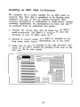
2. Identify the correct socket. The 8087-1 is installed in the
long empty socket located immediately next to the CPU:
3. Make sure the chip is pointing in the right direction. The
notch on the 8087-1 should be pointing to the rear of the
unit (towards the back panel).
56 3. Make sure the chip is pointing in the right direction. The
notch on the 8087-1 should be pointing to the rear of the
unit (towards the back panel).
4. Press the co-processor chip into place in its socket. Once
again, make sure none of the pins are bent or protruding
from the socket.
5. Set the switch on the system board so the computer recog
nizes the 8087 math co-processor. Locate Switch Bank #1
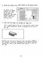
(SW1) as shown in the diagram:
ON
~~~~~~~~
12345678
Right now, switch 2 is ON. To set your system for the
8087-1, turn switch 2 OFF.
57 Installing Expanded Memory
As mentioned before, MS-DOS only recognizes up to 640K of
memory. Any memory above and beyond 640K is referred to as
expanded memory.
Some applications like Lotus 1-2-3 and Dbase III make use of
up to 8 megaqytes (8 MB, or 8,192K) of expanded memory.
On your computer system board, there is room for you to add
one megabyte (1 MB) of expanded memory.
You must add expanded memory in increments of 512K, so you
can add 512K or 1 ME.
As always, before you install anything, MAKE SURE .THE
COMPUTER IS UNPLUGGED FROM THE WALL OUTLET!
1. Purchase the correct memory chips. For every 512K of
expanded memory you install:
Ask your dealer for sixteen (16) 41256 RAM chips (256K RAM x 1). If you plan on using RAM parity, you'll need eighteen instead of sixteen. Th~ chips must be 150 nanoseconds (150ns) or faster. 2. Install the chips in the right sockets on the system board.
In the diagram below, notice there are two banks of em.pty
sockets for installing expanded memory. The banks are
labeled, Bank 0, Bank 1.
=
'~nnniW
DOD
8
DO
OmJ
DOD D~ .
0000000000000000
111111111 OOOOOOO~~
.~~~~~~Ba~ nnl~lh. BankO
58 Bankl
The first 5i2K of expanded memory goes in Bank O. The first
sixteen chips get installed in sockets U50 through U57, and
U60 through U67. If you are using parity RAM, install
another chip at U58 and U59.
If you are installing 1 MB of expanded memory, fill up Bank
1. Remember, the socket at U76 and U77 need to be filled
only if you are using RAM parity-checking.
3. Make sure the chips are pointing the right way.
Make sure you install the RAM chips with the indentations
pointing towards the center of the system board (toward the
back of the unit).
4. Press the chips into place in their proper sockets.
Once again, make sure no pins are bent or protruding from
the socket.
5. Set the switch on the system board so the computer
recognizes the correct amount of expanded memory.
Locate Switch
Bank #2 (SW2)
as shown in the
diagram:
BankO
I
===
I
ON I
T
W~~~-~:~:=
1 2
3
4
1=
0=
=
Right now, all the switches are on. To set your system to recognize the
correct amount of expanded memory, set the switches as above:
59
Using Expanded Memory
As mentioned previously, MS-DOS does not recognize any
memory past 640K. All memory over 640K is called expanded
memory.
Some software packages are written to automatically recognize
expanded memory. For example, Lotus 1-2-3 and Microsoft
Windows 2.0 take full advantage of expanded memory. Other
programs will not recognize expanded memory at all. It depends
specifically on the application you are using.
We have supplied two software programs which are used with
your expanded memory. The fIrst program is EMM.SYS. It
must be installed before the expanded memory can be used. The
second program is ERAMDISK.SYS, a helpful program for
implementing a RAM disk in expanded memory.
EMM.SYS
• The MS-DOS driver for managing expanded memory.
• The following line must appear in the me CONFIG.SYS:
DEVICE = EMM.SYS M3 10
60 ERAMDISK.SYS
This is a driver to turn your expanded memory into a RAM
disk. A RAM disk program sets aside a portion of memory
and treats it as if it were a physical disk drive. In other
words, with two floppy disk drives on your system (Drive "A"
and "B"), the RAM disk becomes Drive "C". If you also have
a hard disk installed, the RAM disk becomes Drive "D".
• To use S12K of expanded memory as a RAM disk, the
following line must appear in CONFIG.SYS:
DEVICE = ERAMDISK.SYS 512
• To use 1MB of expanded memory as a RAM disk, the following
line must appear in CONFIG.SYS:
DEVICE = ERAMDISK.SYS 1024
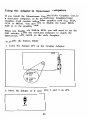
61 Installing a Hard Disk Drive
If your computer is equipped with a hard disk drive, you will
need to prepare the disk for use by "formatting" it. Follow
these simple instructions:
1. The Start-Up Utility Main Menu (As shown on page 9)
should appear on the screen.
2. Type in the letter "C". This option formats your hard disk
drive. This should only be done once when the disk is first
used. This option completely erases all information on the
hard disk, so be careful when running this option.
3. The system displays the question: "Drive C is a fixed disk
drive. Do you want to completely erase it?" Type in "Y" to
format the hard disk drive.
If the hard disk did not come built-in to the unit from the
factory, you can add one yourself. Any hard drive compatible
with the IBM PC-XT can be used. You must also purchase
a hard disk controller that works with the drive you select.
Hard disk and disk controller installation varies depending on
the model you select. You will need to do a low-level
format on the disk before using the Start-Up Utility to do
the high-level format. Consult the manual that comes with
the hard disk for specific instructions
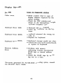
62 Chapter 5:
Trouble Shooting Checklist
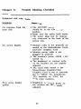
Symptoms and Suggestions
Symptom
Suggestions
No response from the
main unit.
• The ON/OFF switch
should be in the ON or "I"
position.
• Make sure the outlet itself works.
• The power plug may be improp
erly connected to the back of the
system unit.
No screen display.
• Monitor cable is not properly con
nected to the Monochrome Graph
ics/Color Graphics Card
• Monitor power cable is not
plugged in properly
• The monitor's power switch 18 not
turned on.
• The brightness or contrast knobs
on the monitor are not properly
adjusted.
• The small slide switch on the
Monochrome Graphics/Color
Graphics Card is not set correctly.
Set to "MDA" for monochrome
TTL monitors, or "CGA" for
RGB color monitors.
Poor screen display
quality
• Brightness or contrast knobs on
the monitor are not properly
adjusted.
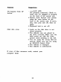
63 Symptom Suggestions
No response from the
keyboard.
• Keyboard cable
not properly connected. Check to
make sure it's plugged in properly
on the back of the system unit.
• System crash. Restart your system
using the reset button on the
back of the system unit. If neces
sary, turn your unit off, then on
again.
• Keyboard lock is not off.
Disk drive error.
• Latch on the disk drive is not
closed properly.
• The diskette was not placed in
the drive correctly. Make sure the
label points up, with the write
protect notch pointing to the left.
• You are using the wrong disk for
start-up. Make sure you are using
an MS-DOS System Disk.
• The diskette is damaged.
• The diskette is unformatted.
If none of these measures work, contact your
computer dealer.
64
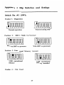
Beeps
1 Long + 1 Short
Base 64K RAM isn't usable. Check the RAM chips.
1 Long
+ 2 Short
The video selector switch on the Monochrome Graphics/
Color Graphics Card isn't properly set.
1 Long + 5 Short
BIOS ROM checksum
IS
incorrect. Replace the BIOS chip.
65 Display Messages
Message
Cause & Suggested Solution
Video error.
• BIOS couldn't find the type of
display adapter requested by the
switch settings.
• Check the DIP switches and
switch on the Monochrome Graph
ics/Color Graphics Card
Keyboard Error 0100.
• Keyboard did not respond.
• Check the connector on the key
board.
Keyboard Error 02XX.
• Keyboard returned the wrong test
code xx.
• Replace the keyboard.
Keyboard Error 04XX.
• Keyboard interrupt would not clear.
• Check Gate Array on the motherboard,
or replace the keyboard.
Memory Address
Error • Problem with memory
addressing. Possibly unconnected
RAM legs or shorted address
lines.
• Check the RAM chips by replac
ing one at a time.
For errors generated by the MS-DOS operating system, consult
the MS-DOS User's Guide.
66
CHAPTER 6: Further Reading
There are many popular books on the market written about
IBM PC-XT Compatible computers and the MS-DOS Operating
System.
Whether searching for a good tutorial for beginners or an
advanced reference manual for experts, you can certainly fmd a
book geared toward your specific needs.
Here is a partial list of books available in retail stores or
public libraries. There are hundreds of other relevant books m
print. Consult your local library for a more complete listing.
These books are available from Howard W.
1-800-428-SAMS for a dealer near you:
Sams & Co. Call
Kate o 'Day, Discovering MS-DOS (4th Printing, 1987)
Steven Simrin, MS-DOS Bible (4th Printing, 1986)
Angermeyer, Fahringer, Jaeger, and Shafer, Tricks of the
MS-DOS Masters (1st Printing, 1987)
O'Day and Angermeyer, Understanding MS-DOS (3rd
Printing, 1987)
67 Other books available from computer retailers and book stores
include:
Quick and Easy PC-DOSjMS-DOS, Alfred Publishing
Company, Inc.
Your IBM-PC Made Easy, Osborne/McGraw-Hill Your IBM: A Guide to the IBM-PC, OsbornejMcGraw-Hill Learning DOS, Microsoft Corporation How to Use Your IBM-PC, American Training Interna
tional Teach Yourself PC-DOS, American Training International. 68 Appendix 1: Dip Switches and Settings Switch Box #1 (SW1)
Position 1: Diagnostics
~ooooooo
~ooooooo 12345678
12345678
Factory testing only
Normal operation
Position 2:
8087-1 Math Co-Processor
TI~oooooo
D~oooooo 12345678
Without 8087 co-processor
12345678
With 8087 co-processor
Position 3 Conventional Memory Amount
~o~ooooo
12345678
TIo~ooooo
512K conventional
Memory
640K conventional
Memory Installed
Position 4
12345678
Not Used
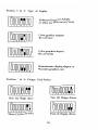
69 Position 5 & 6: Type of Display
ON
~~~~~~~~
Enhanced Graphics Adaptor
or Video Graphics array (VGA)
12345678
ON
DD~~~~~~
Color graphics adaptor
40 x25 mode
12345678
Color graphics adaptor
80x25 mode
Monochrome display adaptor or
Hercules graphics card
Position 7 & 8: Floppy Disk Drives
ON
oooo~o~~
n~~m~~~ One (1) floppy drive
Two (2) floppy drives
12345678
12345678
12345678
~~~m~~~
Three (3) floppy drives
Four (4) floppy drives
12345678
70
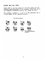
Switch Box #2 (SW2)
Switch SW2 is used for setting the I/O Port address for the
expanded memory installed in the computer. If you have up to
one megabyte of expanded memory, the settings are easy.
The position of switches 1, 2 and 3 on SW2 determine the
o port address of the expanded memory.
I/O Port Address
ON
ON
ON
~~~
~~~
~~~ ~~~
ON
ON
ON
~~~
~~~
~~~ ~~~
208h
2A8h
218h
2B8h
ON
258h
268h
ON
2E8h Expanded Memory disabled 71
1/
72
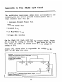
Appendix 2: The Multi I/O Card
The multifunction input/output (Multi I/O) card installed ill the
computer gives you several powerful features packed into a
single expansion card. You get:
• Centronics Parallel Printer Port
• RS232C Serial Port
• Joystick Port
• A Real-Time Clock
• Floppy disk interface
On the Multi I/O Card, you'll [rod two jumper blocks. Jumper
JPl is used for setting the interrupt request levels for the real
time clock. In reality, you should never have to change the
setting of JPl.
Jumper JP2, shown below, is responsible forconftgoring the
ports on the Multi I/O card:
Bracket - - - -_ _ _ _ _ _ _ _ _ _ _ _ _----, RS232 Serial Interface Port Connectors - - - - , Configuration Jumper Block Floppy Disk Interface Connector - - - - - , J5
JP2
Real-Time Clock Interrupt Level Select Jumper Parallel Printer Port Connector _ _ _ _ _ _ _ _ _ _ _ _--' Game Port Connector - - - - - - - - - - - - - - - - - - '
73
Notice how the jumpers are set when the unit leaves the
factory:
25 • • • • • • • • • 1
27~~~~~~~~~
3
IHGFEDCBA
The letters under each row are for illustration only. They do
not actually appear on the jumper block.
Row A: Printer Port Enable
Top of the card
•
Top of the card
~
~
A
Parallel Printer
Enabled
•
A
Parallel Printer Disabled Row B: Printer Port Address
Top of the card
•
Top of the card
~
~
B
•
LPTl
LPT2
B
Row C: Real Time Clock Address
Top of the card
•
Top of the card
~
~
•
A
A
340H
2COH
74
Row D: Serial Port COM2
The Multi I/O card normally has only one serial port named
COMl. If you wish to purchase additional hardware, you can
add a second serial port named COM2. Contact your dealer
for details.
Top of the card
•
~ D
COM2 Enabled Top of the card
~
•
D
COM2 Disabled Row E: Floppy Disk Enable
E
,•
Floppy Disk Enabled
Floppy Disk Disabled
Top of the card
•
Top of the card
~ Row F, G, H:
E
Not Used
Row I: Serial Port COM1
Top of the card
•
Top of the card
~
~ I
•
COMl Enabled
COMl Disabled
I
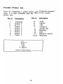
75 Parallel Printer Port
Used for connecting a parallel printer with Centronics standard
input. It is fully compatible with the IBM PC-XT parallel
printer port.
Pin #
Description
Pin #
1
2
3
4
5
6
7
8
9
-STROBE
DATA 0
DATA 1
DATA 2
DATA 3
DATA 4
DATA 5
DATA 6
DATA 7
10
11
12
13
14
15
16
17
18-25
25-pin "D" Style Connector
76 Description
-ACK
+BUSY +PE +S~LECT
-AUTO FD -ERROR -INIT -SELECT INPUT GROUND RS232 Serial Port
Used for connecting a serial printer or modem with RS232
standard input. It is fully compatible with the IBM PC-XT
serial port.
Pin #
Description
CHASSIS GROUND
TRANSMIT DATA
RECEIVE DATA
4
REQUEST TO SEND
5
CLEAR TO SEND
6
DATA SET READY
7
SIGNAL GROUND
8
CARRIER DETECT
20
DATA TERMINAL READY
22
RING INDICATOR
OTHERS NOT USED
1
2
3
25-pin "D" Style Connector
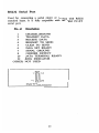
77 Joystick Port
Used for connecting a joystick mechanism to the Laser Turbo
XT using a is-pin "D" style connector.
r -xc~;din-;t;- -, +5V
I
I
I
1
Switch 4
r'
I X I
r
1
1
9
~-1
,
d'
oor onate r
y r
I~Vr--------l
I
2
I
10
I
3
'1 4
I
12
lye
I
"
13
5
I
r Gnd
I
I Y
I
Iy Coord.nate
r
I
r
l_____ jl2Jrt~~:11IL~-----J
-. ,
.
Switch 3
Switch 2
78
Appendix 3: Monochrome Graphics /Color
Graphics Card
Overview
As a color graphics adapter, this card provides a flexible
interface to RGB monitors, as well as color and monochrome
composite monitors. Graphic resolutions of 320 x 200 or 640 x
200 are available.
When selected for monochrome operation, the Monochrome
Graphics/Color Graphics Card is fully compatible with the
Hercules graphics card, providing 720 x 348 resolution.
When the Monochrome Graphics/Color Graphics
Card is installed in a Laser Computer, the slide
switch on the card faceplate is used to select
color graphics or monochrome operation.
MDAIol
eGA
l!J
Once you have set pole 5 and 6 or the DIP switch SWl to
ON, there are no other switches to set, and no need to open
the system unit. The Laser BIOS on the graphics adapter
assures perfect operation when inside a Laser Computer.
79
Using the Adapter in Non-Laser Computers
If you install the Monochrome Graphics/Color Graphics Card in
a non-Laser computer, or the Monochrome Graphics/Color
Graphics Card coexists with another graphics card (e.g. EGA,
CGA or MDA). You may have to disable the Laser BIOS
built in to the graphics card.
When you disable the built-in BIOS, you will need to set the
DIP switches inside the non-Laser computer to match the
MDA/CGA slide switch on the card's faceplate.
To disable the built-in BIOS:
1. Locate the Jumper JP2 on the Graphics Adapter.
2. Move the jumper so it covers pins 2 and 3 on JP2.
@
•
JP2
80 With the jumper set in this manner, the BIOS on the Mono
chrome Graphics/Color Graphics Card is disabled.
If your Laser computer is installed with EGA card, please refer
to user manual provided for the EGA card:
If your Laser computer is installed with hard disk controller
card please refer to the user manual provided for the hard disk
controller.
81 82 Appendix 4: Glossary of Computer Terms
As with any industry, the computer world seems to have a
language all its own. Listed below are some of the most
common words and phrases you will see in relation to personal
computers.
8087 Coprocessor
The 8087 is a computer chip designed to work with the
computer's main microprocessor. The 8087 chip is designed
specifically to speed up mathematical calculations for large
spreadsheets, etc.
8086
The 8086 is a main microprocessor chip. This chip could
be considered the "brain" of an IBM or compatible com
puter because the 8086 chip processes all of your
computer's commands. When you program your computer
to do something, the 8086 chip receives your commands,
and executes them.
8086-1
The 8086-1 chip is an improved version of the 8086 chip.
The 8086-1 replaces the 8086 and performs the same
functions that the 8086 chip does. However, the 8086-1 is
a "turbo" computer chip. The 8086-1 can run at a speed
of either 4.77 MHz or the turbo/faster speed of 10 MHz.
Some IBM software programs are designed to run only at
4.77 MHz. To run these programs, your computer would
need a microprocessor that runs at 4.77 MHz. However,
many software titles written today are more flexible. You
can run them at either 4.77 MHz, or you can run them
at "turbo speed". The advantage to owning a computer
with a turbo chip like the 8086-1 is that your computer
can execute commands and work for you faster when
software allows it to. Happily, almost all IBM software
these days lets you take advantage of this turbo speed
feature.
83
AT Style Keyboard
IBM has manufactured a few different models of personal
computers (PC, PC JR., PC/XT, PC/AT). The PC/AT
style keyboard is generally considered to be superior. The
AT style keyboard is designed to feel like an IBM Selec
tric typewriter and has large SHIFf and RETURN keys. It
is often said that the AT style keyboard feels more com
fortable and is easier to work on because of its features.
BIOS
BIOS stands for Basic Input/Output System. The BIOS is
the central computer program which organizes your entire
computer. The BIOS acts much like a computer "road
map". The BIOS contains a list of computer locations for
everything inside of your computer from computer chips to
floppy disk drives. When the microprocessor needs to send
a signal, it asks the BIOS how to get there.
As an example - you iI1struct your computer to read infor
mation from disk drive "B". The microprocessor receives
your command. It then asks the BIOS where disk drive
"B" is located. At this point, the BIOS will give the
microprocessor specific directions from the location of the
microprocessor chip to the location of the disk drive. The
microprocessor will then send an electrical impulse along
the route the BIOS has described, and this signal will in
struct the disk drive to begin reading information. Without
the BIOS, your'microprocessor would be "all dressed up,
with no place to go" .
Boot Up
This is a slang term used to describe the computer's start
up procedure. You boot up your computer when you turn
power to your computer "on".
84
Bracket
Brackets are the narrow metal pieces which cover the eight
holes on the back of your computer. The eight holes
correspond to the eight expansion slots in your computer.
Brackets are used for two main purposes: one, they help
anchor expansion cards securely; and two, they cover the
openings for empty expansion slots so that dust and dirt
can not enter your computer and damage it.
CGA
CGA stands for Color Graphics Adaptor.
Clock
A clock keeps time, and computers can have the option of
a clock installed. This option can be used many ways, but
the main idea is always the same. If you have a clock in
your computer, it will keep time for you.
Cold Start
When all power to your computer is turned off, and you
then tum power to your computer "on", you "have "cold
started" your computer.
COM
COM is the computer abbreviation for a serial computer
port. Computers can be configured for more than one
serial port. Because of this, COM ports are always desig
nated as COM!, COM2, COM3, etc.
Configure
To configure means to specifically set something up a cer
tain way. When a computer dealer says that his computer
is "factory pre-set", he means that the computer has been
configured or set-up a certain way.
Conventional Memory
MS DOS regularly addresses (or accesses) a maximum of
640K RAM. Therefore, OK to 640K RAM is considered
conventional memory.
85
DIP Switch
The DIP in DIP switch stands for Dual In-line Package.
DIP switches on your computer must be turned either
"on" or "off' in order to tell your computer some very
basic information. The main DIP switches inform the
computer how much memory is installed, how many floppy
disk drives there are, etc. The computer uses this critical
information to test and orient itself every time the power
is turned on. If a DIP switch is set incorrectly, your
computer may not function properly.
DIN Connector
A DIN connector is a round plug connection. The most
common type of DIN connector is a five pin DIN connec
tor, which is a round plug with five pins (male connector)
or five holes (female connector).
DSDD
DSDD stands for Double Sided Double Density, and refers
to floppy diskettes. DSDD disks are the most common
type of floppy disks used on IBM and compatible comput
ers. You can store more information on DSDD disks than
on SSDD (Single Sided Double Density) disks, because
DSDD diskettes can hold information on both sides of the
diskette.
EGA
EGA stands for Enhanced Graphics Adaptor, providing a
much higher quality picture on your computer's monitor.
EMS
EMS stands for Expanded Memory Specification. Some
software such as Lotus 1-2-3 uses EMS. The conventional
computer memory maximum is 640K. EMS is a set of
standards where programs can use up to eight megabytes
of memory, above beyond the 640K barrier.
86 Expansion Card
An expansion card is a device you plug into a computer
which allows you to add new features. Expansion cards are
delicate electronic instruments, and should be handled with
care. Expansion cards come in a variety of sizes(7", 10",
and even full length 14" sizes ).
Expansion cards are inserted in your computer's expansion
slots. At the bottom of each expansion card you will find
a 62 "gold fingered" band (31 gold stripes on each side).
The gold fIngers connect the card to your computer's main
circuitry. The expansion cards are secured in their slots by
brackets which are fIrmly screwed into the main unit
casing. Real gold is used on the gold fingers so that the
expansion cards are not susceptible to tarnishing. Tarnishing
can interfere with an expansion card's connection to the
motherboard.
Expansion Slot
Your Computer computer has eight expansion slots. They
are located on the left hand side of the computer at the
rear. These expansion slots can be used to add features to
your computer via expansion cards.
Female
A female connector on a computer will have holes (in
comparison to a male connector which will have pins).
Floppy Diskette
A floppy diskette is a disk which contains magnetic media.
A floppy disk is used to store information. The information
is stored on a floppy disk via the read/write head of your
floppy disk drive.
Floppy Disk Drive
Floppy disk drives read (retrieve) or write (save) informa
tion on floppy diskettes.
87 Formatted
Formatted diskettes are "mapped out". When you format a
disk, the disk drive creates divisions ("sectors") on the
diskette, and numbers them. With this, data that is saved
on a formatted disk can be located in, say, sector 1, etc.
Formatting gives your computer the ability to locate data
with precise coordinates on each floppy diskette.
Hard Disk Drive
A hard disk drive (or fixed disk) can store much more
information than a floppy disk drive. A hard drive is made
of many layers of special magnetic media, specifIcally de
signed to hold high quantities of data. As a rough ex
ample, installing a 20 MB hard drive in your computer is
like adding 125 floppy disk drives to that same computer.
A hard disk allows you to access information more rapidly,
because you do not have to repeatedly load floppy disk
ettes.
One note of caution - because a hard drive is made up
of so many layers of specialized magnetic media, it is
much more delicate. Use care when handling or moving a
computer with an installed hard drive, and carefully read
all precautions before handling or moving any hard disk
drive.
Hardware
Hardware is considered to be any part of your computer
that you can actually touch (in contrast to software which
is considered to be information stored on magnetic medial
floppy diskettes). Items of hardware include printers, moni
tors, floppy disk drives, etc.
Hercules/Hercules-Compatible
Hercules or Hercules-compatible is a monitor display
standard of 720H x 350V resolution. 720 refers to the
number of tiny dots .(called "pixels") appearing across the
screen.
88
I.C. Socket
I.e. socket stands for Integrated Circuit socket. An I.C.
socket is a location on the computer motherboard where
you can insert a computer chip without soldering.
Initializing Diskettes
When you initialize a floppy diskette, you are "formatting"
the floppy diskette. See fonnatted.
LPT
LPT is an abbreviation for computer parallel ports. Since
computers can have more than one parallel port, parallel
ports are always designated LPT1, LPTI, LPT3, etc.
Male
Male computer connectors have pins (as compared to
female connectors, which have holes).
MHz
MHz IS the abbreviation for Megahertz. Megahertz IS a
unit of measurement for computer's microprocessor speed.
Microprocessor
See 8086 or 8086-1.
Monochrome
Monochrome means "single color" displays. Typical mono
chrome monitors are either green or amber with black
backgrounds.
Motherboard
The motherboard is the main circuitry board of your
computer which houses all computer microcircuitry and
offers room for expansion via I.C. sockets and expansion
slots.
Nanoseconds
Nanoseconds are very small increments of time (one
billionth of a second). Nanoseconds are used as a rating
method for RAM chips; the lower the number of nanos
econds, the faster the RAM chip. 120 nanosecond (or
"ns") chips are faster/better quality than 150ns chips.
89
Parallel Port
Parallel ports are computer ports typically used for parallel
Centronics printer hook-up.
RAM
RAM stands for Random Access Memory. You can read
or write to RAM memory (versus ROM memory, which
you can only read from). RAM memory is dynamic, you
can change RAM memory contents by adding to or delet
ing from RAM at your discretion.
Re-Boot
"Re-booting" your computer means to restart the computer
from scratch.
Read
When you read information from a floppy disk, you are
retrieving information that has been stored on the diskette.
Real Time Clock
A real time clock keeps time for your computer even
when it is turned off (real time clocks traditionally have a
battery back-up). A real time clock is an optional accessory
for IBM XT's which frees you from having to repeatedly
enter the date and time' every time you boot MS DOS.
Resolution
Every monitor display picture you see is made up of tiny
dots (called pixels). Resolution is typically given in terms
of horizontal dots by vertical dots. The more dots (pixels)
in the resolution, the clearer your picture will be.
As an example - 640H x 200V (a typical CGA color
resolution) is not as good, or as clear, as 640H x 350V
(typical EGA color resolution).
RGB
RGB stands for Red-Green-Blue. RGB is a term used to
describe one type of monitor display for your computer.
RGB monitors are color monitors which divide, and then
recombine the picture signal so as to make the picture
clearer.
90
ROM
ROM stands for Read Only Memory. ROM memory is
information your computer can readily access, necessary
information. ROM memory differs from RAM memory in
that you can not "write" or save information to the ROM
memory locations. The only thing you can do to ROM
memory is retrieve, or read, from it.
Serial Port
A computer serial port is typically labelled as a communi
cations port. A serial port can be used to hook up either
a serial printer or a modem, both of which "communicate"
between the computer and the outside world.
Software
Software is best described as any information you load (or
+read +) into your computer. Software is contained on
floppy diskettes. Typically, software allows you to do some
thing with your computer (i.e. play a game, write a
letter,or design a spreadsheet for mathematical calculations).
Turbo
Turbo lS a term used to mean "faster speed". A turbo
computer (like your computer) runs at a faster speed than
other computers. Turbo computers work faster, giving you
the advantage of being done faster with whatever it is you
want to do.
TTL
TTL stands for Transistor-to-Transistor-Logic. TTL is a
term used to describe one type of display monitor. TTL
monitors are typically monochrome monitors that will always
give you a crisper picture, due to their advanced + transis
tor logic.
Write
When you save information you are +writing+ information
to your floppy diskette or hard disk drive. + Write + is the
technical term for saving information to your computer.
91
Write Protect
Every floppy diskette has a notch (or cut-out portion) on
it. This notch allows the computer disk drive heads to
write information onto the floppy disk. When you cover
this notch, you can not write information onto the floppy
disk. Write protect "tabs" are typically included with floppy
diskettes when purchased so that you can use this safe
guard measure for important data.
Warm Boot
Restarting your computer using the Reset Button on the
back of the system unit or the CTRL-ALT-DEL key
sequence.
92