1
PacketFence Administration Guide
for version 4.1.0
PacketFence Administration Guide
by Inverse Inc.
Version 4.1.0 - December 2013
Copyright © 2008-2013 Inverse inc.
Permission is granted to copy, distribute and/or modify this document under the terms of the GNU Free Documentation License, Version 1.2 or
any later version published by the Free Software Foundation; with no Invariant Sections, no Front-Cover Texts, and no Back-Cover Texts. A copy
of the license is included in the section entitled "GNU Free Documentation License".
The fonts used in this guide are licensed under the SIL Open Font License, Version 1.1. This license is available with a FAQ at: http://scripts.sil.org/OFL
Copyright © Barry Schwartz, http://www.crudfactory.com, with Reserved Font Name: "Sorts Mill Goudy".
Copyright © Raph Levien, http://levien.com/, with Reserved Font Name: "Inconsolata".
Table of Contents
About this Guide ................................................................................................................. 1
Other sources of information ......................................................................................... 1
Introduction ....................................................................................................................... 2
Features .................................................................................................................... 2
Network Integration .................................................................................................... 5
Components .............................................................................................................. 6
System Requirements .......................................................................................................... 7
Assumptions .............................................................................................................. 7
Minimum Hardware Requirements ................................................................................. 7
Operating System Requirements .................................................................................... 8
Installation ........................................................................................................................ 9
OS Installation ............................................................................................................ 9
Software Download .................................................................................................... 11
Software Installation .................................................................................................. 11
Configuration .................................................................................................................... 13
First Step ................................................................................................................. 13
Web-based Administration Interface .............................................................................. 14
Global configuration file (pf.conf) ................................................................................. 14
Apache Configuration ................................................................................................. 14
SELinux .................................................................................................................... 15
Roles Management .................................................................................................... 15
Authentication .......................................................................................................... 16
Network Devices Definition (switches.conf) .................................................................... 18
Default VLAN/role assignment ...................................................................................... 21
Inline enforcement configuration .................................................................................. 21
Hybrid mode ............................................................................................................ 22
DHCP and DNS Server Configuration (networks.conf) ........................................................ 22
Production DHCP access ............................................................................................. 23
Routed Networks ....................................................................................................... 25
FreeRADIUS Configuration ............................................................................................ 28
Starting PacketFence Services ...................................................................................... 33
Log files .................................................................................................................. 34
Passthrough ............................................................................................................. 34
Proxy Interception ..................................................................................................... 35
Configuration by example ................................................................................................... 36
Assumptions ............................................................................................................. 36
Network Interfaces .................................................................................................... 37
Switch Setup ............................................................................................................ 38
switches.conf ............................................................................................................ 39
pf.conf .................................................................................................................... 40
networks.conf ........................................................................................................... 42
Inline enforcement specifics ........................................................................................ 43
Optional components ......................................................................................................... 45
Blocking malicious activities with violations ................................................................... 45
Compliance Checks .................................................................................................... 49
RADIUS Accounting .................................................................................................... 52
Oinkmaster ............................................................................................................... 53
Floating Network Devices ............................................................................................ 53
Guests Management .................................................................................................. 55
Statement of Health (SoH) .......................................................................................... 58
Apple Wireless Profile Provisioning ............................................................................... 60
Copyright © 2008-2013 Inverse inc.
iii
SNMP Traps Limit ......................................................................................................
Billing Engine ...........................................................................................................
Portal Profiles ...........................................................................................................
OAuth2 Authentication ...............................................................................................
Gaming Devices Registration .......................................................................................
Operating System Best Practices ..........................................................................................
Iptables ...................................................................................................................
Log Rotations ...........................................................................................................
Logrotate (recommended) ...........................................................................................
Log4perl ...................................................................................................................
High Availability ........................................................................................................
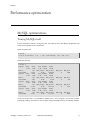
Performance optimization ...................................................................................................
MySQL optimizations ..................................................................................................
Captive Portal Optimizations .......................................................................................
Frequently Asked Questions ................................................................................................
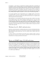
Technical introduction to VLAN enforcement ..........................................................................
Introduction .............................................................................................................
VLAN assignment techniques .......................................................................................
More on SNMP traps VLAN isolation .............................................................................
Technical introduction to Inline enforcement ..........................................................................
Introduction .............................................................................................................
Device configuration ..................................................................................................
Access control ..........................................................................................................
Limitations ...............................................................................................................
Technical introduction to Hybrid enforcement ........................................................................
Introduction .............................................................................................................
Device configuration ..................................................................................................
More on VoIP Integration ...................................................................................................
CDP and LLDP are your friend .....................................................................................
VoIP and VLAN assignment techniques ..........................................................................
What if CDP/LLDP feature is missing .............................................................................
Additional Information .......................................................................................................
Commercial Support and Contact Information .........................................................................
GNU Free Documentation License .........................................................................................
A. Administration Tools ......................................................................................................
pfcmd .....................................................................................................................
pfcmd_vlan ..............................................................................................................
Web Admin GUI ........................................................................................................
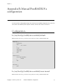
B. Manual FreeRADIUS 2 configuration ..................................................................................
Configuration ............................................................................................................
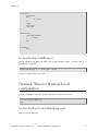
Optional: Wired or Wireless 802.1X configuration .............................................................
Copyright © 2008-2013 Inverse inc.
61
61
62
63
64
65
65
65
65
65
66
73
73
76
77
78
78
78
79
82
82
82
82
82
84
84
84
85
85
85
86
87
88
89
90
90
92
94
95
95
96
iv
Chapter 1
About this Guide
This guide will walk you through the installation and the day to day administration of the PacketFence
solution.
The latest version of this guide is available at http://www.packetfence.org/documentation/
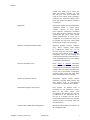
Other sources of information
Network Devices Configuration Guide
Covers switch, controllers and access points
configuration.
Developers Guide
Covers captive portal customization, VLAN
management customization and instructions
for supporting new hardware.
CREDITS
This is, at least, a partial file of PacketFence
contributors.
NEWS.asciidoc
Covers noteworthy features, improvements
and bugfixes by release.
UPGRADE.asciidoc
Covers compatibility related changes, manual
instructions and general notes about
upgrading.
ChangeLog
Covers all changes to the source code.
These files are included in the package and release tarballs.
Copyright © 2008-2013 Inverse inc.
About this Guide
1
Chapter 2
Introduction
PacketFence is a fully supported, trusted, Free and Open Source network access control (NAC) system.
Boosting an impressive feature set including a captive portal for registration and remediation, centralized
wired and wireless management, 802.1X support, layer-2 isolation of problematic devices, integration
with the Snort/Suricata IDS and the Nessus vulnerability scanner; PacketFence can be used to effectively
secure networks - from small to very large heterogeneous networks.
Features
Out of band (VLAN Enforcement)
PacketFence’s operation is completely out of
band when using VLAN enforcement which
allows the solution to scale geographically
and to be more resilient to failures.
In Band (Inline Enforcement)
PacketFence can also be configured to be
in-band, especially when you have nonmanageable network switches or access
points. PacketFence can also work with
both VLAN and Inline enforcement activated
for maximum scalability and security while
allowing older hardware to still be secured
using Inline enforcement.
Hybrid support (Inline Enforcement with RADIUS
support)
PacketFence can also be configured as
hybrid, if you have a manageable device
that supports 802.1x and/or mac-auth. This
feature can be enabled using a RADIUS
attribute (MAC address, SSID, port) or using
full inline mode on the equipment.
Voice over IP (VoIP) support
Also called IP Telephony (IPT), VoIP is
fully supported (even in heterogeneous
environments) for multiple switch vendors
(Cisco, Edge-Core, HP, LinkSys, Nortel
Networks and many more).
802.1X
802.1X wireless and wired is supported
through a FreeRADIUS module.
Wireless integration
PacketFence integrates perfectly with
wireless networks through a FreeRADIUS
Copyright © 2008-2013 Inverse inc.
Introduction
2
Chapter 2
module. This allows you to secure your
wired and wireless networks the same
way using the same user database and
using the same captive portal, providing a
consistent user experience. Mixing Access
Points (AP) vendors and Wireless Controllers
is supported.
Registration
PacketFence supports an optional registration
mechanism similar to "captive portal"
solutions. Contrary to most captive
portal solutions, PacketFence remembers
users who previously registered and will
automatically give them access without
another authentication. Of course, this is
configurable. An Acceptable Use Policy can
be specified such that users cannot enable
network access without first accepting it.
Detection of abnormal network activities
Abnormal network activities (computer
virus, worms, spyware, traffic denied
by establishment policy, etc.) can be
detected using local and remote Snort or
Suricata sensors. Beyond simple detection,
PacketFence layers its own alerting and
suppression mechanism on each alert type. A
set of configurable actions for each violation
is available to administrators.
Proactive vulnerability scans
Either Nessus or OpenVAS vulnerability
scans can be performed upon registration,
scheduled or on an ad-hoc basis. PacketFence
correlates the scan engine vulnerability ID’s
of each scan to the violation configuration,
returning content specific web pages about
which vulnerability the host may have.
Isolation of problematic devices
PacketFence supports several isolation
techniques, including VLAN isolation with
VoIP support (even in heterogeneous
environments) for multiple switch vendors.
Remediation through a captive portal
Once trapped, all network traffic is
terminated by the PacketFence system.
Based on the node’s current status
(unregistered, open violation, etc), the user
is redirected to the appropriate URL. In
the case of a violation, the user will be
presented with instructions for the particular
situation he/she is in reducing costly help
desk intervention.
Command-line and Web-based management
Web-based and command-line interfaces for
all management tasks.
Copyright © 2008-2013 Inverse inc.
Introduction
3
Chapter 2
Guest Access
PacketFence supports a special guest VLAN
out of the box. You configure your network
so that the guest VLAN only goes out to the
Internet and the registration VLAN and the
captive portal are the components used to
explain to the guest how to register for access
and how his access works. This is usually
branded by the organization offering the
access. Several means of registering guests
are possible. PacketFence does also support
guest access bulk creations and imports.
Gaming devices registration
A registered user can access a special Web
page to register a gaming device of his own.
This registration process will require login
from the user and then will register gaming
devices with pre-approved MAC OUI into a
configurable category.
PacketFence is developed by a community of developers located mainly in North America. More
information can be found at http://www.packetfence.org.
Copyright © 2008-2013 Inverse inc.
Introduction
4
Chapter 2
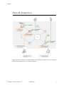
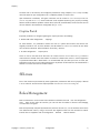
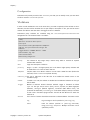
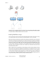
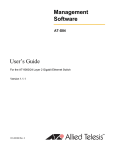
Network Integration
VLAN enforcement is pictured in the above diagram. Inline enforcement should be seen as a simple flat
network where PacketFence acts as a firewall / gateway.
Copyright © 2008-2013 Inverse inc.
Introduction
5
Chapter 2
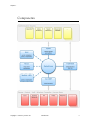
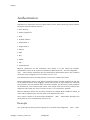
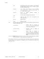
Components
Copyright © 2008-2013 Inverse inc.
Introduction
6
Chapter 3
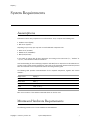
System Requirements
Assumptions
PacketFence reuses many components in an infrastructure. Thus, it requires the following ones:
∏ Database server (MySQL)
∏ Web server (Apache)
Depending on your setup you may have to install additional components like:
∏ DHCP server (ISC DHCP)
∏ RADIUS server (FreeRADIUS)
∏ NIDS (Snort/Suricata)
In this guide, we assume that all those components are running on the same server (i.e., "localhost" or
"127.0.0.1") that PacketFence will be installed on.
Good understanding of those underlying component and GNU/Linux is required to install PacketFence. If
you miss some of those required components, please refer to the appropriate documentation and proceed
with the installation of these requirements before continuing with this guide.
The following table provides recommendations for the required components, together with version
numbers :
MySQL server
MySQL 5.1
Web server
Apache 2.2
DHCP server
DHCP 3
RADIUS server
FreeRADIUS 2.1.12
Snort
Snort 2.8 or 2.9
Suricata
Suricata 1.4.1
More recent versions of the software mentioned above can also be used.
Minimum Hardware Requirements
The following provides a list of server hardware recommendations:
Copyright © 2008-2013 Inverse inc.
System Requirements
7
Chapter 3
∏
∏
∏
∏
Intel or AMD CPU 3 GHz
4 GB of RAM
100 GB of disk space (RAID-1 recommended)
1 Network card
∏ +1 for high-availability
∏ +1 for intrusion detection
Operating System Requirements
PacketFence supports the following operating systems on the i386 or x86_64 architectures:
∏
∏
∏
∏
Red Hat Enterprise Linux 6.x Server
Community ENTerprise Operating System (CentOS) 6.x
Debian 7.0 (Wheezy)
Ubuntu 12.04 LTS
Make sure that you can install additional packages from your standard distribution. For example, if you
are using Red Hat Enterprise Linux, you have to be subscribed to the Red Hat Network before continuing
with the PacketFence software installation.
Other distributions such as Fedora and Gentoo are known to work but this document doesn’t cover them.
Services start-up
PacketFence takes care of handling the operation of the following services:
∏
∏
∏
∏
∏
Web server (httpd)
DHCP server (dhcpd)
FreeRADIUS server (radiusd)
Snort/Suricata Network IDS (snort/suricata)
Firewall (iptables)
Make sure that all the other services are automatically started by your operating system!
Copyright © 2008-2013 Inverse inc.
System Requirements
8
Chapter 4
Installation
This section will guide you through the installation of PacketFence together with its dependencies.
OS Installation
Install your distribution with minimal installation and no additional packages. Then:
∏
∏
∏
∏
Disable
Disable
Disable
Disable
Firewall
SELinux
AppArmor
resolvconf
Make sure your system is up to date and your yum or apt-get database is updated. On a RHEL-based
system, do:
yum update
On a Debian or Ubuntu system, do:
apt-get update
apt-get upgrade
RedHat-based systems
Note
Includes CentOS and Scientific Linux. Both i386 and x86_64 architectures supported.
Several third party repositories are required to pull all the proper PacketFence dependencies:
∏ Repoforge, also previously known as rpmforge
∏ EPEL, Extra Packages for Enterprise Linux
∏ OpenFusion
Install the proper repositories in yum so it can directly lookup for packages:
For RHEL 6.x / CentOS 6.x. Copyright © 2008-2013 Inverse inc.
Installation
9
Chapter 4
# rpm -Uvh http://pkgs.repoforge.org/rpmforge-release/rpmforgerelease-0.5.3-1.el6.rf.`uname -m`.rpm
# rpm -Uvh http://download.fedoraproject.org/pub/epel/6/`uname -i`/epelrelease-6-8.noarch.rpm
# rpm -Uvh http://repo.openfusion.net/centos6-`uname -i`/openfusionrelease-0.6.2-1.of.el6.noarch.rpm
Then disable these repositories by default. Under /etc/yum.repos.d/ edit rpmforge.repo, epel.repo
and openfusion.repo and set enabled to 0 under every section like this:
enabled = 0
Under RHEL 6.x / Centos 6.x, you must exclude perl-Apache-Test from rpmforge and openfusion repository.
Edit /etc/yum.repos.d/rpmforge.repo and add to the section [rpmforge] the line:
exclude = perl-Apache-Test*
Edit /etc/yum.repos.d/openfusion.repo and add to the section [of] the line:
exclude = perl-Apache-Test*
RHEL 6.x
Note
These are extra steps are required for RHEL 6 systems only. Derivatives such as CentOS
or Scientific Linux don’t need to take the extra steps.
RedHat Enterprise Linux users need to take an additional setup step. If you are not using the RHN
Subscription Management from RedHat you need to enable the optional channel by running the following
as root:
rhn-channel --add --channel=rhel-`uname -m`-server-optional-6
RedHat doesn’t seem to provide perl-Net-Telnet perl-XML-Simple perl-SOAP-Lite packages.
PacketFence needs it so we will install it from the rpmforge-extras repository now:
yum install perl-Net-Telnet perl-XML-Simple perl-SOAP-Lite --enablerepo=rpmforgeextras,rpmforge
Debian and Ubuntu
All the PacketFence dependencies are available through the official repositories.
Copyright © 2008-2013 Inverse inc.
Installation
10
Chapter 4
Software Download
PacketFence provides a RPM repository for RHEL / CentOS instead of a single RPM file.
For Debian and Ubuntu, PacketFence also provides package repositories.
These repositories contain all required dependencies to install PacketFence. This provides numerous
advantages:
∏ easy installation
∏ everything is packaged as RPM/deb (no more CPAN hassle)
∏ easy upgrade
Software Installation
RHEL / CentOS
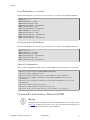
In order to use the repository, create a file named /etc/yum.repos.d/PacketFence.repo with the
following content:
[PacketFence]
name=PacketFence Repository
baseurl=http://inverse.ca/downloads/PacketFence/RHEL$releasever/$basearch
gpgcheck=0
enabled=0
Once the repository is defined, you can install PacketFence with all its dependencies, and the required
external services (Database server, DHCP server, RADIUS server) using:
yum groupinstall --enablerepo=PacketFence,epel,rpmforge,of Packetfence-complete
Or, if you prefer, to install only the core PacketFence without all the external services, you can use:
yum install --enablerepo=PacketFence,epel,rpmforge,of packetfence
Debian and Ubuntu
In order to use the repository, create a file named /etc/apt/sources.list.d/packetfence.list with
the following content when using Debian 7.0 (Wheezy):
deb http://inverse.ca/downloads/PacketFence/debian wheezy wheezy
Copyright © 2008-2013 Inverse inc.
Installation
11
Chapter 4
Or when using Ubuntu 12.04 LTS:
deb http://inverse.ca/downloads/PacketFence/ubuntu precise precise
Once the repository is defined, you can install PacketFence with all its dependencies, and the required
external services (Database server, DHCP server, RADIUS server) using:
sudo apt-key adv --keyserver keys.gnupg.net --recv-key 0x810273C4
sudo apt-get update
sudo apt-get install packetfence
In order to use ipset in inline mode, you must install two news dependencies and compile kernel modules:
sudo apt-get install xtables-addons-source xtables-addons-common
sudo module-assistant auto-install xtables-addons
Copyright © 2008-2013 Inverse inc.
Installation
12
Chapter 5
Configuration
In this section, you’ll learn how to configure PacketFence. PacketFence will use MySQL, Apache, ISC DHCP,
iptables and FreeRADIUS. As previously mentioned, we assume that those components run on the same
server on which PacketFence is being installed.
First Step
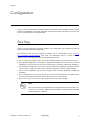
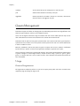
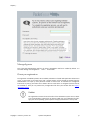
The first step after installing the necessary packages is the configuration step. PacketFence provides an
helpful and detailed web-based configurator.
Like mentioned at the end of the packages installation, fire up a web browser and go to https://
@ip_of_packetfence:1443/configurator. From there, the configuration process is splited in six (6)
distinctive steps, after which you’ll have a working PacketFence setup.
∏ Step 1: Enforcement technique. You’ll choose either VLAN enforcement, inline enforcement or both;
∏ Step 2: Network configuration. You’ll be able to configure the network interfaces of the system as well as
assigning the correct interfaces for each of the required types of the chosen enforcement technique(s);
∏ Step 3: Database configuration. This step will create the PacketFence database and populate it with the
correct structure. A MySQL user will also be created and assigned to the newly created database;
∏ Step 4: General configuration. You will need to configure some of the basic PacketFence configuration
parameters;
∏ Step 5: Administrative user. This step will ask you to create an administrative user that will be able to
access the web-based adminsitration interface once the services are functionals;
∏ Step 6: Let’s do this! See the status of your configuration and start your new NAC!
Note
Keep in mind that the resulting PacketFence configuration will be located under /usr/
local/pf/conf/ and the configuration files can always be adjusted by hand afterward
or from PacketFence’s Web GUI.
Copyright © 2008-2013 Inverse inc.
Configuration
13
Chapter 5
Web-based Administration Interface
PacketFence provides a web-based administration interface for easy configuration and operational
management. If you went through PacketFence’s web-based configuration tool, you should have set the
password for the admin user. If not, the default password is also admin.
Once PacketFence is started,
@ip_of_packetfence>:1443/
the
administration
interface
is
available
at:
https://
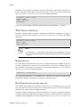
Global configuration file (pf.conf)
The /usr/local/pf/conf/pf.conf file contains the PacketFence general configuration. For example,
this is the place where we inform PacketFence it will work in VLAN isolation mode.
All the default parameters
pf.conf.defaults.
and
their
descriptions
are
stored
in
/usr/local/pf/conf/
In order to override a default parameter, define it and set it in pf.conf.
/usr/local/pf/conf/documentation.conf holds the complete list of all available parameters.
All these parameters are also accessible through the web-based administration interface under the
Configuration tab. It is highly recommended that you use the web-based administration interface of
PacketFence for any configuration changes.
Apache Configuration
The PacketFence´s Apache configuration are located in /usr/local/pf/conf/httpd.conf.d/.
In this directory you have three important files: httpd.admin, httpd.portal, httpd.webservice.
∏ httpd.admin is used to manage PacketFence admin interface
∏ httpd.portal is used to manage PacketFence captive portal interface
∏ httpd.webservices is used to manage PacketFence webservices interface
These files have been written using the Perl language and are completely dynamic - so they activate
services only on the network interfaces provided for this purpose.
Copyright © 2008-2013 Inverse inc.
Configuration
14
Chapter 5
The other files in this directory are managed by PacketFence using templates, so it is easy to modify
these files based on your configuration. SSL is enabled by default to secure access.
Upon PacketFence installation, self-signed certificates will be created in /usr/local/pf/conf/ssl
(server.key and server.crt). Those certificates can be replaced anytime by your 3rd-party or existing
wildcard certificate without problems. Please note that the CN (Common Name) needs to be the same as
the one defined in the PacketFence configuration file (pf.conf).
Captive Portal
Important parameters to configure regarding the captive portal are the following:
∏ Redirect URL under Configuration � Trappings
For some browsers, is it preferable to redirect the user to a specific URL instead of the URL the user
originally intended to visit. For these browsers, the URL defined in redirecturl will be the one where
the user will be redirected. Affected browsers are Firefox 3 and later.
∏ IP under Configuration � Captive portal
This IP is used as the web server who hosts the common/network-access-detection.gif which is
used to detect if network access was enabled. It cannot be a domain name since it is used in registration
or quarantine where DNS is black-holed. It is recommended that you allow your users to reach your
PacketFence server and put your LAN’s PacketFence IP. By default we will make this reach PacketFence’s
website as an easier and more accessible solution.
SELinux
Even if this feature may be wanted by some organizations, PacketFence will not run properly if SELinux
is set to enforced. You will need to explicitly disable it in the /etc/selinux/config file.
Roles Management
Roles in PacketFence can be created from PacketFence administrative GUI - from the Configuration �
Users � Roles section. From this interface, you can also limit the number of devices users belonging
to certain roles can register.
Roles are dynamically computed by PacketFence, based on the rules (ie., a set of conditions and actions)
from authentication sources, using a first-match wins algorithm. Roles are then matched to VLAN or
internal roles on equipment from the Configuration � Network � Switches module.
Copyright © 2008-2013 Inverse inc.
Configuration
15
Chapter 5
Authentication
PacketFence can authenticate users that register devices via the captive portal using various methods.
Among the supported methods, there are:
∏ Active Directory
∏ Apache htpasswd file
∏ Email
∏ Facebook (OAuth 2)
∏ Github (OAuth 2)
∏ Google (OAuth 2)
∏ Kerberos
∏ LDAP
∏ Null
∏ RADIUS
∏ SMS
∏ Sponsored Email
Moreover, PacketFence can also authenticate users defined in its own internal SQL database.
Authentication sources can be created from PacketFence administrative GUI - from the Configuration �
Users � Sources section. Alternatively (but not recommended), authentication sources, rules, conditions
and actions can be configured from conf/authentication.conf.
Each authentication sources you define will have a set of rules, conditions and actions.
Multiple authentication sources can be defined, and will be tested in the order specified (note that they
can be reordered from the GUI by dragging it around). Eeach source can have multiple rules, which will
also be tested in the order specified. Rules can also be reordered, just like sources. Finally, conditions
can be defined for a rule to match certain criterias. If the criterias match (one ore more), action are then
applied and rules testing stop, across all sources as this is a "first match wins" operation.
When no condition is defined, the rule will be considered as a fallback. When a fallback is defined, all
actions will be applied fory any users that match in the authentication source.
Once a source is defined, it can be used from Configuration � Main � Portal Profiles and Pages. Each
portal profile has a list of authentication sources to use.
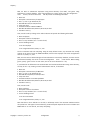
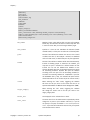
Example
Let’s say we have two roles: guest and employee. First, we define them Configuration � Users � Roles.
Copyright © 2008-2013 Inverse inc.
Configuration
16
Chapter 5
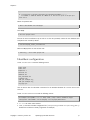
Now, we want to authenticate employees using Active Directory (over LDAP), and guests using
PacketFence’s internal database - both using PacketFence’s captive portal. From the Configuration �
Users � Sources, we select Add source � AD. We provide the following information:
∏
∏
∏
∏
∏
∏
∏
∏
Name: ad1
Description: Active Directory for Employees
Host: 192.168.1.2:389 without SSL/TLS
Base DN: CN=Users,DC=acme,DC=local
Scope: One-level
Username Attribute: sAMAccountName
Bind DN: CN=Administrator,CN=Users,DC=acme,DC=local
Password: acme123
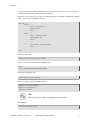
Then, we add a rule by clicking on the Add rule button and provide the following information:
∏
∏
∏
∏
Name: employees
Description: Rule for all employees
Don’t set any condition (as it’s a catch-all rule)
Set the following actions:
∏ Set role employee
∏ Set unregistration date January 1st, 2020
Test the connection and save everything. Using the newly defined source, any username that actually
matches in the source (using the sAMAccountName) will have the employee role and an unregistration
date set to January 1st, 2020.
Now, since we want to authenticate guests from PacketFence’s internal SQL database, accounts must be
provisionned manually. You can do so from the Configuration � Users � Create section. When creating
guests, specify "guest" for the Set role action, and set an access duration for 1 day.
If you would like to differentiate user authentication and machine authentication using Active Directory,
one way to do it is by creating a second authentication sources, for machines:
∏
∏
∏
∏
∏
∏
∏
∏
Name: ad1
Description: Active Directory for Machines
Host: 192.168.1.2:389 without SSL/TLS
Base DN: CN=Computers,DC=acme,DC=local
Scope: One-level
Username Attribute: servicePrincipalName
Bind DN: CN=Administrator,CN=Users,DC=acme,DC=local
Password: acme123
Then, we add a rule:
∏
∏
∏
∏
Name: machines
Description: Rule for all machines
Don’t set any condition (as it’s a catch-all rule)
Set the following actions:
∏ Set role machineauth
∏ Set unregistration date January 1st, 2020
Note that when a rule is defined as a catch-all, it will always match if the username attribute matches
the queried one. This applies for Active Directory, LDAP and Apache htpasswd file sources. Kerberos and
RADIUS will act as true catch-all, and accept everything.
Copyright © 2008-2013 Inverse inc.
Configuration
17
Chapter 5
Network Devices Definition (switches.conf)
This section applies only for VLAN enforcement. Users planning to do inline enforcement only can skip
this section.
PacketFence needs to know which switches, access points or controllers it manages, their type and
configuration. All this information is stored in /usr/local/pf/conf/switches.conf. You can modify
the configuration directly in the switches.conf file or you can do it in the Web Administration panel
under Configuration � Network � Switches.
This files contains a default section including:
∏ List of VLANs managed by PacketFence
∏ Default SNMP read/write communities for the switches
∏ Default working mode (see note about working mode below)
and a switch section for each switch (managed by PacketFence) including:
∏
∏
∏
∏
Switch IP
Switch vendor/type
Switch uplink ports (trunks and non-managed ports)
per-switch re-definition of the VLANs (if required)
Note
switches.conf is loaded at startup. A restart is required when changes are made
to this file.
Working modes
There are three different working modes:
Testing
pfsetvlan writes in the log files what it would normally do, but it
doesn’t do anything.
Registration
pfsetvlan automatically-register all MAC addresses seen on the switch
ports. As in testing mode, no VLAN changes are done.
Production
pfsetvlan sends the SNMP writes to change the VLAN on the switch
ports.
SNMP v1, v2c and v3
PacketFence uses SNMP to communicate with most switches. Starting with 1.8, PacketFence now supports
SNMP v3. You can use SNMP v3 for communication in both directions: from the switch to PacketFence
and from PacketFence to the switch.
Copyright © 2008-2013 Inverse inc.
Configuration
18
Chapter 5
From PacketFence to a switch
Edit the switch config file (/usr/local/pf/conf/switches.conf) and set the following parameters:
SNMPVersion = 3
SNMPUserNameRead = readUser
SNMPAuthProtocolRead = MD5
SNMPAuthPasswordRead = authpwdread
SNMPPrivProtocolRead = AES
SNMPPrivPasswordRead = privpwdread
SNMPUserNameWrite = writeUser
SNMPAuthProtocolWrite = MD5
SNMPAuthPasswordWrite = authpwdwrite
SNMPPrivProtocolWrite = AES
SNMPPrivPasswordWrite = privpwdwrite
From a switch to PacketFence
Edit the switch config file (/usr/local/pf/conf/switches.conf) and set the following parameters:
SNMPVersionTrap = 3
SNMPUserNameTrap = readUser
SNMPAuthProtocolTrap = MD5
SNMPAuthPasswordTrap = authpwdread
SNMPPrivProtocolTrap = AES
SNMPPrivPasswordTrap = privpwdread
Switch Configuration
Here is a switch configuration example in order to enable SNMP v3 in both directions on a Cisco Switch.
snmp-server engineID local AA5ED139B81D4A328D18ACD1
snmp-server group readGroup v3 priv
snmp-server group writeGroup v3 priv read v1default write v1default
snmp-server user readUser readGroup v3 auth md5 authpwdread priv aes 128
privpwdread
snmp-server user writeUser writeGroup v3 auth md5 authpwdwrite priv aes 128
privpwdwrite
snmp-server enable traps port-security
snmp-server enable traps port-security trap-rate 1
snmp-server host 192.168.0.50 version 3 priv readUser port-security
Command-Line Interface: Telnet and SSH
Warning
Privilege detection is disabled in the current PacketFence version due to some issues
(see #1370). So make sure that the cliUser and cliPwd you provide always get you
into a privileged mode (except for Trapeze hardware).
Copyright © 2008-2013 Inverse inc.
Configuration
19
Chapter 5
PackeFence needs sometimes to establish an interactive command-line session with a switch. This can
be done using Telnet. Starting with 1.8, you can now use SSH. In order to do so, edit the switch config
file (/usr/local/pf/conf/switches.conf) and set the following parameters:
cliTransport = SSH (or Telnet)
cliUser = admin
cliPwd = admin_pwd
cliEnablePwd =
It can also be done through the Web Administration Interface under Configuration � Switches.
Web Services Interface
PackeFence sometimes needs to establish a dialog with the Web Services capabilities of a switch. In
order to do so, edit the switch config file (/usr/local/pf/conf/switches.conf) and set the following
parameters:
wsTransport = http (or https)
wsUser = admin
wsPwd = admin_pwd
Note
as of PacketFence 1.9.1 few switches require Web Services configuration in order to
work. It can also be done through the Web Administration Interface under Configuration
� Switches.
Radius Secret
For certain authentication mechanism, such as 802.1X or MAC Authentication, the RADIUS server needs
to have the network device in its client list. As of PacketFence 3.0, we now use a database backend to
store the RADIUS client information. In order to do so, edit the switch config file (/usr/local/pf/conf/
switches.conf) and set the following parameters:
radiusSecret= secretPassPhrase
Also, starting with PacketFence 3.1, the RADIUS secret is required for our support of RADIUS Dynamic
Authentication (Change of authorization or Disconnect) as defined in RFC3576.
Role-based enforcement support
Some network devices support the assignment of a specific set of rules (firewall or ACLs) to a user. The
idea is that these rules can be a lot more precise to control what a user can or cannot do compared to
VLAN which have a larger network management overhead.
PacketFence supports assigning roles on devices that supports it. The current role assignment strategy is
to assign it along with the VLAN (that may change in the future). A special internal role to external role
assignment must be configured in the switch configuration file (/usr/local/pf/conf/switches.conf).
Copyright © 2008-2013 Inverse inc.
Configuration
20
Chapter 5
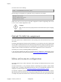
The current format is the following:
Format: <rolename>Role=<controller_role>
And you assign it to the global roles parameter or the per-switch one. For example:
adminRole=full-access
engineeringRole=full-access
salesRole=little-access
would return the full-access role to the nodes categorized as admin or engineering and the role
little-access to nodes categorized as sales.
Caution
Make sure that the roles are properly defined on the network devices prior to assigning
roles!
Default VLAN/role assignment
This section applies only for VLAN enforcement. Users planning to do inline enforcement only can skip
this section.
The default VLAN assignment technique used in PacketFence is a per-switch one. The correct default VLAN
for a given MAC is determined based on the computed role by PacketFence during the registration process
for the device, or dynamically during an 802.1X authentication. The computed internal role will then be
mapped to either a VLAN or an external role for the specific equipement the user is connected to.
This allows you to do easy per-building VLAN/role segmentation.
If you need more flexibility than what can be defined from the PacketFence’s authentication sources
(rules/conditions/actions) take a look at the FAQ entry Custom VLAN assignment behavior available online.
Inline enforcement configuration
This section applies only for Inline enforcement. Users planning to do VLAN enforcement only can skip
this section.
The inline enforcement is a very convenient method of performing access control on older network
hardware who is not capable of doing VLAN enforcement or who is not compatible with PacketFence. This
technique is covered in details in the "Technical introduction to Inline enforcement" section.
An important configuration parameter to have in mind when configuring inline enforcement is that the
DNS reached by this users should be your actual production DNS server. The next section shows you how
to configure the proper inline interface and it is there that you should refer to the proper production DNS.
Copyright © 2008-2013 Inverse inc.
Configuration
21
Chapter 5
Inline enforcement uses ipset to mark nodes as registered, unregistered and isolated. It is also
now possible to use multiple inline interfaces, a node registered on the first inline interface
is mark with is couple ip:mac, so when the node try to register on an other inline interface
PacketFence detect that the node is already registered on the first VLAN. It is also possible to enable
inline.should_reauth_on_vlan_change to force user to reauthenticate when they change VLAN. ipset also
provides a better reponse time under inline enforcement and now we just have to wait 10s after the
registration to access to internet.
The outgoing interface should be specified by adding in pf.conf the option interfaceSNAT in inline section.
It is a comma delimited list of network interfaces like eth0,eth0.100. It’s also possible to specify a network
that will be routed instead of using NAT by adding in conf/networks.conf an option nat=no under one
or more network section.
Another important setting is the gateway statement. Since it this the only way to get the PacketFence
server inline interface ip address, it is mandatory to set it to this ip (which is supposed to be the same
as in the ip statement of the inline interface in conf/pf.conf) .
Hybrid mode
This section applies for hybrid support for the manageable devices that support 802.1x or mac-auth.
Hybrid enforcement is a mixed method that offers the use of inline enforcement mode with VLAN
enforcement mode on the same device. This technique is covered in details in the "Technical introduction
to Hybrid enforcement" section
DHCP and DNS Server Configuration
(networks.conf)
PacketFence automatically generates the DHCP configuration files for Registration, Isolation and Inline
VLANs. This is done by editing the network interfaces from the configuration module of the administration
Web interface (see the First Step section).
network
Network subnet
netmask
Network mask
gateway
PacketFence IP address in this network
next_hop
Used only with routed networks; IP address
of the router in this network (This is used
to locally create static routes to the routed
networks). See the Routed Networks section)
domain-name
DNS name
Copyright © 2008-2013 Inverse inc.
Configuration
22
Chapter 5
dns
PacketFence IP address in this network. In
inline type, set it to a valid DNS production
server
dhcp_start
Starting IP address of the DHCP scope
dhcp_end
Ending IP address of the DHCP scope
dhcp_default_lease_time
Default DHCP lease time
dhcp_max_lease_time
Maximum DHCP lease time
type
vlan-registration or vlan-isolation or inline
named
Is PacketFence the DNS for this network ?
(Enabled/Disabled) set it to enabled
dhcpd
Is PacketFence the DHCP server for this
network ? (Enabled/Disabled) set it to
enabled
nat
Is PacketFence route or NAT the traffic for this
network ? (yes/no) NAT enabled by default,
set to no to route
When starting PacketFence generates the DHCP configuration files by reading the information provided
in networks.conf:
The DHCP configuration file is written to var/conf/dhcpd.conf using conf/dhcpd.conf as a template.
Production DHCP access
In order to perform all of its access control duties, PacketFence needs to be able to map MAC addresses
into IP addresses.
For all the networks/VLANs where you want PacketFence to have the ability to isolate a node or to have
IP information about nodes, you will need to perform one of the techniques below.
Also note that this doesn’t need to be done for the registration, isolation VLANs and inline interfaces
since PacketFence acts as the DHCP server in these networks.
IP Helpers (recommended)
If you are already using IP Helpers for your production DHCP in your production VLANs this approach is
the simplest one and the one that works the best.
Add PacketFence’s management IP address as the last ip helper-address statement in your network
equipment. At this point PacketFence will receive a copy of all DHCP requests for that VLAN and will record
what IP were distributed to what node using a pfdhcplistener daemon.
Copyright © 2008-2013 Inverse inc.
Configuration
23
Chapter 5
By default no DHCP Server should be running on that interface where you are sending the requests. This
is by design otherwise PacketFence would reply to the DHCP requests which would be a bad thing.
Obtain a copy of the DHCP traffic
Get a copy of all the DHCP Traffic to a dedicated physical interface in the PacketFence server and
run pfdhcplistener on that interface. It will involve configuring your switch properly to perform port
mirroring (aka network span) and adding in PacketFence the proper interface statement at the operating
system level and in pf.conf.
/etc/sysconfig/network-scripts/ifcfg-eth2:
DEVICE=eth2
ONBOOT=yes
BOOTPROTO=none
Add to pf.conf: (IPs are not important they are there only so that PacketFence will start)
[interface eth2]
mask=255.255.255.0
type=dhcp-listener
gateway=192.168.1.5
ip=192.168.1.1
Restart PacketFence and you should be good to go.
Interface in every VLAN
Because DHCP traffic is broadcast traffic, an alternative for small networks with few local VLANs is to
put a VLAN interface for every VLAN on the PacketFence server and have a pfdhcplistener listen on
that VLAN interface.
On the network side you need to make sure that the VLAN truly reaches all the way from your client to
your DHCP infrastructure up to the PacketFence server.
On the PacketFence side, first you need an operating system VLAN interface like the one below. Stored
in /etc/sysconfig/network-scripts/ifcfg-eth0.1010:
# Engineering VLAN
DEVICE=eth0.1010
ONBOOT=yes
BOOTPROTO=static
IPADDR=10.0.101.4
NETMASK=255.255.255.0
VLAN=yes
Then you need to specify in pf.conf that you are interested in that VLAN’s DHCP by setting type to
dhcp-listener.
Copyright © 2008-2013 Inverse inc.
Configuration
24
Chapter 5
[interface eth0.1010]
mask=255.255.255.0
type=dhcp-listener
gateway=10.0.101.1
ip=10.0.101.4
Repeat the above for all your production VLANs then restart PacketFence.
Host production DHCP on PacketFence
It’s an option. Just modify conf/dhcpd.conf so that it will host your production DHCP properly and make
sure that a pfdhcplistener runs on the same interface where production DHCP runs. However, please
note that this is NOT recommended. See this ticket to see why.
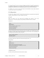
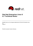
Routed Networks
If your isolation and registration networks are not locally-reachable (at layer 2) on the network, but routed
to the PacketFence server, you’ll have to let the PacketFence server know this. PacketFence can even
provide DHCP and DNS in these routed networks and provides an easy to use configuration interface.
Copyright © 2008-2013 Inverse inc.
Configuration
25
Chapter 5
For dhcpd, make sure that the clients DHCP requests are correctly forwarded (IP Helpers in the remote
routers) to the PacketFence server. Then make sure you followed the instructions in the DHCP and DNS
Server Configuration (networks.conf) for your locally accessible network.
If we consider the network architecture illustrated in the above schema, conf/pf.conf will include the
local registration and isolation interfaces only.
[interface eth0.2]
enforcement=vlan
ip=192.168.2.1
type=internal
mask=255.255.255.0
[interface eth0.3]
enforcement=vlan
ip=192.168.3.1
type=internal
mask=255.255.255.0
Note
PacketFence will not start unless you have at least one internal interface, so you need
to create local registration and isolation VLANs even if you don’t intend to use them.
Also, the internal interfaces are the only ones on which dhcpd listens, so the remote
registration and isolation subnets need to point their DHCP helper-address to those
particular IPs.
Then you need to provide the routed networks information to PacketFence. You can do it through the GUI
in Administration � Networks (or in conf/networks.conf).
conf/networks.conf will look like this:
[192.168.2.0]
netmask=255.255.255.0
gateway=192.168.2.1
next_hop=
domain-name=registration.example.com
dns=192.168.2.1
dhcp_start=192.168.2.10
dhcp_end=192.168.2.200
dhcp_default_lease_time=300
dhcp_max_lease_time=600
type=vlan-registration
named=enabled
dhcpd=enabled
Copyright © 2008-2013 Inverse inc.
Configuration
26
Chapter 5
[192.168.3.0]
netmask=255.255.255.0
gateway=192.168.3.1
next_hop=
domain-name=isolation.example.com
dns=192.168.3.1
dhcp_start=192.168.3.10
dhcp_end=192.168.3.200
dhcp_default_lease_time=300
dhcp_max_lease_time=600
type=vlan-isolation
named=enabled
dhcpd=enabled
[192.168.20.0]
netmask=255.255.255.0
gateway=192.168.20.254
next_hop=192.168.2.254
domain-name=registration.example.com
dns=192.168.2.1
dhcp_start=192.168.20.10
dhcp_end=192.168.20.200
dhcp_default_lease_time=300
dhcp_max_lease_time=600
type=vlan-registration
named=enabled
dhcpd=enabled
[192.168.30.0]
netmask=255.255.255.0
gateway=192.168.30.254
next_hop=192.168.3.254
domain-name=isolation.example.com
dns=192.168.3.1
dhcp_start=192.168.30.10
dhcp_end=192.168.30.200
dhcp_default_lease_time=300
dhcp_max_lease_time=600
type=vlan-isolation
named=enabled
dhcpd=enabled
DHCP clients on the registration and isolation networks receive the PF server IP as their DNS server
(dns=x.x.x.x), and PF spoofs DNS responses to force clients via the portal. However, clients could manually
configure their DNS settings to escape the portal. To prevent this you will need to apply an ACL on the
access router nearest the clients, permitting access only to the PF server and local DHCP broadcast traffic.
For example, for the VLAN 20 remote registration network:
Copyright © 2008-2013 Inverse inc.
Configuration
27
Chapter 5
ip access-list extended PF_REGISTRATION
permit ip any host 192.168.2.1
permit udp any any eq 67
deny ip any any log
interface vlan 20
ip address 192.168.20.254 255.255.255.0
ip helper-address 192.168.2.1
ip access-group PF_REGISTRATION in
If your edge switches support vlan-isolation you can also apply the ACL there. This has the advantage of
preventing machines in isolation from attempting to attack each other.
FreeRADIUS Configuration
This section presents the FreeRADIUS configuration steps. In some occasions, a RADIUS server is mandatory
in order to give access to the network. For example, the usage of WPA2-Enterprise (Wireless 802.1X), MAC
authentication and Wired 802.1X all requires a RADIUS server to authenticate the users and the devices,
and then to push the proper VLAN to the network equipment.
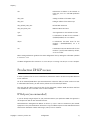
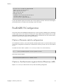
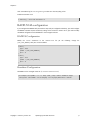
Option 1: Dynamic switch configuration
Since PacketFence version 4.1 you are now be able to enable dynamic clients. It mean that when you add
a new switch configuration in PacketFence´s administration interface you don´t have to restart radiusd
service.
To enable this feature make a symlink in /usr/local/pf/raddb/site-enabled directory:
ln -s ../sites-available/dynamic-clients dynamic-clients
and of course restart radiusd:
/usr/local/pf/bin/pfcmd service radiusd restart
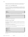
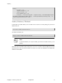
Option 2: Authentication against Active Directory (AD)
Replace /usr/local/pf/raddb/modules/mschap with the following configuration:
Copyright © 2008-2013 Inverse inc.
Configuration
28
Chapter 5
mschap {
use_mppe = yes
require_encryption = yes
require_strong = yes
with_ntdomain_hack = yes
ntlm_auth = "/usr/bin/ntlm_auth --request-nt-key --username=%{%{StrippedUser-Name}:-%{mschap:User-Name:-None}} --challenge=%{mschap:Challenge:-00} --ntresponse=%{mschap:NT-Response:-00}"
}
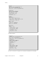
Samba / Kerberos / Winbind
Install Samba 3 and NOT Samba 4. You can either use the sources or use the package for your OS. For
RHEL/CentOS, do:
yum install samba krb5-workstation
For Debian and Ubuntu, do:
apt-get install samba winbind krb5-user
Note
If you have Windows 7 PCs in your network, you need to use Samba version 3.5.0 (or
greater).
When done with the Samba install, modify your /etc/hosts in order to add the FQDN of your Active
Directory servers. Then, you need to modify /etc/krb5.conf. Here is an example for the DOMAIN.NET
domain for Centos/RHEL:
Copyright © 2008-2013 Inverse inc.
Configuration
29
Chapter 5
[logging]
default = FILE:/var/log/krb5libs.log
kdc = FILE:/var/log/krb5kdc.log
admin_server = FILE:/var/log/kadmind.log
[libdefaults]
default_realm = DOMAIN.NET
dns_lookup_realm = false
dns_lookup_kdc = false
ticket_lifetime = 24h
forwardable = yes
[realms]
DOMAIN.NET = {
kdc = adserver.domain.net:88
admin_server = adserver.domain.net:749
default_domain = domain.net
}
[domain_realm]
.domain.net = DOMAIN.NET
domain.net = DOMAIN.NET
[appdefaults]
pam = {
debug = false
ticket_lifetime = 36000
renew_lifetime = 36000
forwardable = true
krb4_convert = false
}
For Debian and Ubuntu:
[logging]
default = FILE:/var/log/krb5libs.log
kdc = FILE:/var/log/krb5kdc.log
admin_server = FILE:/var/log/kadmind.log
[libdefaults]
default_realm = DOMAIN.NET
ticket_lifetime = 24h
forwardable = yes
[appdefaults]
pam = {
debug = false
ticket_lifetime = 36000
renew_lifetime = 36000
forwardable = true
krb4_convert = false
}
Next, edit /etc/samba/smb.conf. Again, here is an example for our DOMAIN.NET for Centos/RHEL:
Copyright © 2008-2013 Inverse inc.
Configuration
30
Chapter 5
[global]
workgroup = DOMAIN
server string = pf_server_name
security = ads
passdb backend = tdbsam
realm = DOMAIN.NET
encrypt passwords = yes
winbind use default domain = yes
client NTLMv2 auth = yes
preferred master = no
domain master = no
local master = no
load printers = no
log level = 1 winbind:5 auth:3
For Debian and Ubuntu:
[global]
workgroup = DOMAIN
server string = Samba Server Version %v
security = ads
realm = DOMAIN.NET
password server = 192.168.1.1
domain master = no
local master = no
preferred master = no
winbind separator = +
winbind enum users = yes
winbind enum groups = yes
winbind use default domain = yes
winbind nested groups = yes
winbind refresh tickets = yes
template homedir = /home/%D/%U
template shell = /bin/bash
client use spnego = yes
client ntlmv2 auth = yes
encrypt passwords = yes
restrict anonymous = 2
log file = /var/log/samba/log.%m
max log size = 50
Issue a kinit and klist in order to get and verify the Kerberos token:
# kinit administrator
# klist
After that, you need to start samba, and join the machine to the domain:
# service smb start
# chkconfig --level 345 smb on
# net ads join -U administrator
Copyright © 2008-2013 Inverse inc.
Configuration
31
Chapter 5
Note that for Debian and Ubuntu you will probably have this error:
# kinit succeeded but ads_sasl_spnego_krb5_bind failed: Invalid credentials
# Join to domain is not valid: Invalid credentials
Finally, start winbind, and test the setup using ntlm_auth and radtest:
# service winbind start
# chkconfig --level 345 winbind on
For Centos/RHEL:
# usermod -a -G wbpriv pf
For Debian and Ubuntu:
# chgrp pf /var/run/samba/winbindd_privileged/
# ntlm_auth --username myDomainUser
# radtest -t mschap -x myDomainUser myDomainPassword localhost:18120 12
testing123
Sending Access-Request of id 108 to 127.0.0.1 port 18120
User-Name = "myDomainUser"
NAS-IP-Address = 10.0.0.1
NAS-Port = 12
Message-Authenticator = 0x00000000000000000000000000000000
MS-CHAP-Challenge = 0x79d62c9da4e55104
MS-CHAP-Response =
0x000100000000000000000000000000000000000000000000000091c843b420f0dec4228ed2f26bff07d5e49ad9a2974
rad_recv: Access-Accept packet from host 127.0.0.1 port 18120, id=108,
length=20
Option 3: Local Authentication
Add your user’s entries at the end of the /usr/local/pf/raddb/users file with the following format:
username Cleartext-Password := "password"
Option 4: Authentication against OpenLDAP
To be contributed...
Tests
Test your setup with radtest using the following command and make sure you get an Access-Accept
answer:
Copyright © 2008-2013 Inverse inc.
Configuration
32
Chapter 5
# radtest dd9999 Abcd1234 localhost:18120 12 testing123
Sending Access-Request of id 74 to 127.0.0.1 port 18120
User-Name = "dd9999"
User-Password = "Abcd1234"
NAS-IP-Address = 255.255.255.255
NAS-Port = 12
rad_recv: Access-Accept packet from host 127.0.0.1:18120, id=74, length=20
Debug
First, check the FreeRADIUS logs. The file is located at /usr/local/pf/logs/radius.log.
If this didn’t help, run FreeRADIUS in debug mode. To do so, start it using the following command:
# radiusd -X -d /usr/local/pf/raddb
Additionally there is a raddebug tool that can extract debug logs from a running FreeRADIUS daemon.
PacketFence’s FreeRADIUS is preconfigured with such support.
In order to have an output from raddebug, you need to either:
a. Make sure user pf has a shell in /etc/passwd, add /usr/sbin to PATH (export PATH=/usr/sbin:
$PATH) and execute raddebug as pf
b. Run raddebug as root (less secure!)
Now you can run raddebug easily:
raddebug -t 300 -d /usr/local/pf/raddb
The above will output FreeRADIUS' debug logs for 5 minutes. See man raddebug for all the options.
Starting PacketFence Services
Once PacketFence is fully installed and configured, start the services using the following command :
service packetfence start
You may verify using the chkconfig command that the PacketFence service is automatically started at
boot time.
Copyright © 2008-2013 Inverse inc.
Configuration
33
Chapter 5
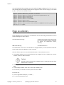
Log files
Here are the most important PacketFence log files:
/usr/local/pf/logs/packetfence.log
PacketFence Core Log
/usr/local/pf/logs/portal_access_log
Apache – Captive Portal Access Log
/usr/local/pf/logs/portal_error_log
Apache – Captive Portal Error Log
/usr/local/pf/logs/admin_access_log
Apache – Web Admin/Services Access Log
/usr/local/pf/logs/admin_error_log
Apache – Web Admin/Services Error Log
/usr/local/pf/logs/admin_debug_log
Apache – Web Admin Debug Log
/usr/local/pf/logs/webservices_access_log
Apache – Webservices Access Log
/usr/local/pf/logs/webservices_error_log
Apache – Webservices Error Log
There are other log files in /usr/local/pf/logs/ that could be relevant depending on what issue you
are experiencing. Make sure you take a look at them.
The logging system’s configuration file is /usr/local/pf/conf/log.conf. It contains the configuration
for the packetfence.log file (Log::Log4Perl) and you normally don’t need to modify it.
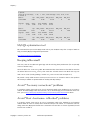
Passthrough
In order to use the passthrough feature in PacketFence, you need to enable it from the GUI in Configuration
� Trapping and check Passthrough.
There are two solutions for passthroughs - one using DNS resolution and iptables and the other one using
Apache’s mod_proxy module. When enabled, PacketFence will use pfdns if you defined Passthroughs, or
Apache mod-proxy if you defined Proxy Passthroughs to allow trapped devices to reach web sites.
*DNS passthrough: Add a new FQDN (should be a wildcard domain like *.google.com) in the Passthroughs
section. When PacketFence receives a DNS request for this domain, it will answer the real IP address and
punch a hole in the firewall (using iptables) to allow access. With this method, PacketFence must be the
default gateway of your device.
*mod_proxy passthrough: Add a new FQDN (should be a wildcard domain like *.google.com) in the Proxy
Passthroughs section. For this FQDN, PacketFence will answer the IP address of the captive portal and when
a device hits the captive portal, PacketFence will detect that this FQDN has a passthrough configuration
and will forward the traffic to mod_proxy.
These two methods can be used together but DNS-based passthroughs have higher priority.
Copyright © 2008-2013 Inverse inc.
Configuration
34
Chapter 5
Proxy Interception
In PacketFence you are now able to intercept proxy request and forward them to the captive portal. It
only work in layer 2 network because packetfence must be the default gateway of your device. In order
to use the Proxy Interception feature, you need to enable it from the GUI in Configuration � Trapping
and check Proxy Interception.
Add the port you want to intercept, like 8080 3128 and add a new entry in the /etc/hosts file to resolv
the fqdn of the captive portal to 127.0.0.1. The modification of the hosts file is really important because
apache try to resolv the fqdn of the captive portal and it must be 127.0.0.1.
Copyright © 2008-2013 Inverse inc.
Configuration
35
Chapter 6
Configuration by example
Here is an end-to-end sample configuration of PacketFence in "Hybrid" mode (VLAN mode and Inline mode
at the same time).
Assumptions
Throughout this configuration example we use the following assumptions for our network infrastructure:
∏ There are two different types of manageable switches in our network: Cisco Catalyst 2900XL and Cisco
Catalyst 2960, and one unmanageable device.
∏ VLAN 1 is the "normal" VLAN - users with the "default" role will be assigned to it
∏ VLAN 2 is the registration VLAN (unregistered devices will be put in this VLAN)
∏ VLAN 3 is the isolation VLAN (isolated devices will be put in this VLAN)
∏ VLANs 2 and 3 are spanned throughout the network
∏ VLAN 4 is the MAC detection VLAN (void VLAN)
∏ VLAN 4 must be defined on all the switches that do not support port-security (in our example Catalyst
2900XL do not support port-security with static MAC address). No need to put it in the trunk port.
∏ VLAN 5 is the inline VLAN (In-Band, for unmanageable devices)
∏ We want to isolate computers using Limewire (peer-to-peer software)
∏ We use Snort as NIDS
∏ The traffic monitored by Snort is spanned on eth1
∏ The DHCP server on the PacketFence box that will take care of IP address distribution in VLANs 2, 3 and 5
∏ The DNS server on the PacketFence box that will take care of domain resolution in VLANs 2 and 3
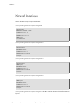
The network setup looks like this:
VLAN ID
VLAN Name
Subnet
Gateway
PacketFence Address
1
Normal
192.168.1.0/24
192.168.1.1
192.168.1.5
2
Registration
192.168.2.0/24
192.168.2.1
192.168.2.1
3
Isolation
192.168.3.0/24
192.168.3.1
192.168.3.1
4
Mac Detection
5
Inline
192.168.5.0/24
192.168.5.1
192.168.5.1
100
Voice
Copyright © 2008-2013 Inverse inc.
Configuration by example
36
Chapter 6
Network Interfaces
Here are the NICs startup scripts on PacketFence.
/etc/sysconfig/network-scripts/ifcfg-eth0:
DEVICE=eth0
BROADCAST=192.168.1.255
IPADDR=192.168.1.5
NETMASK=255.255.255.0
NETWORK=192.168.1.0
ONBOOT=yes
TYPE=Ethernet
/etc/sysconfig/network-scripts/ifcfg-eth0.2:
DEVICE=eth0.2
ONBOOT=yes
BOOTPROTO=static
IPADDR=192.168.2.1
NETMASK=255.255.255.0
VLAN=yes
/etc/sysconfig/network-scripts/ifcfg-eth0.3:
DEVICE=eth0.3
ONBOOT=yes
BOOTPROTO=static
IPADDR=192.168.3.1
NETMASK=255.255.255.0
VLAN=yes
/etc/sysconfig/network-scripts/ifcfg-eth0.5:
DEVICE=eth0.5
ONBOOT=yes
BOOTPROTO=static
IPADDR=192.168.5.1
NETMASK=255.255.255.0
VLAN=yes
/etc/sysconfig/network-scripts/ifcfg-eth1. This NIC is used for the mirror of the traffic monitored
by Snort.
Copyright © 2008-2013 Inverse inc.
Configuration by example
37
Chapter 6
DEVICE=eth1
ONBOOT=yes
BOOTPROTO=none
Trap receiver
PacketFence uses snmptrapd as the trap receiver. It stores the community name used by the switch to
send traps in the switch config file (/usr/local/pf/conf/switches.conf):
[default]
SNMPCommunityTrap = public
Switch Setup
In our example, we enable linkUp/linkDown on a Cisco 2900LX and Port Security on a Cisco Catalyst 2960.
Please consult the Network Devices Configuration Guide for the complete list of supported switches and
configuration instructions.
linkUp/linkDown + MAC Notification
On the 2900XL.
global setup
snmp-server enable traps snmp linkdown linkup
snmp-server enable traps mac-notification
snmp-server host 192.168.1.5 trap version 2c public snmp mac-notification
mac-address-table notification interval 0
mac-address-table notification
mac-address-table aging-time 3600
on each interface
switchport mode access
switchport access vlan 4
snmp trap mac-notification added
Port Security
On the 2960.
global setup
Copyright © 2008-2013 Inverse inc.
Configuration by example
38
Chapter 6
snmp-server enable traps port-security
snmp-server enable traps port-security trap-rate 1
snmp-server host 192.168.1.5 version 2c public port-security
On each interface, you need to initialize the port security by authorizing a fake MAC address with the
following commands
switchport
switchport
switchport
switchport
switchport
switchport
access vlan 4
port-security
port-security
port-security
port-security
port-security
maximum 2
maximum 1 vlan access
violation restrict
mac-address 0200.0000.00xx
where xx stands for the interface index.
Note
Don’t forget to update the startup-config.
switches.conf
Note
You can use the Web Administration interface instead of performing the configuration
in the flat files.
Here is the /usr/local/pf/conf/switches.conf file for our setup. See Network Device Definition for
more information about the content of this file.
Copyright © 2008-2013 Inverse inc.
Configuration by example
39
Chapter 6
[default]
SNMPCommunityRead = public
SNMPCommunityWrite = private
SNMPommunityTrap = public
SNMPVersion = 1
defaultVlan = 1
registrationVlan = 2
isolationVlan = 3
macDetectionVlan = 4
VoIPEnabled = no
[192.168.1.100]
type = Cisco::Catalyst_2900XL
mode = production
uplink = 24
[192.168.1.101]
type = Cisco::Catalyst_2960
mode = production
uplink = 25
defaultVlan = 10
radiusSecret=useStrongerSecret
If you want to have a different read/write communities name for each switch, declare it in each switch
section.
pf.conf
Here is the /usr/local/pf/conf/pf.conf file for our setup. For more information about pf.conf see
Global configuration file (pf.conf) section.
Copyright © 2008-2013 Inverse inc.
Configuration by example
40
Chapter 6
[general]
domain=yourdomain.org
#Put your External/Infra DNS servers here
dnsservers=4.2.2.2,4.2.2.1
dhcpservers=192.168.2.1,192.168.3.1,192.168.5.1
[trapping]
registration=enabled
detection=enabled
range=192.168.2.0/24,192.168.3.0/24,192.168.5.0/24
[interface eth0]
mask=255.255.255.0
type=management
gateway=192.168.1.1
ip=192.168.1.5
[interface eth0.2]
mask=255.255.255.0
type=internal
enforcement=vlan
gateway=192.168.2.1
ip=192.168.2.1
[interface eth0.3]
mask=255.255.255.0
type=internal
enforcement=vlan
gateway=192.168.3.1
ip=192.168.3.1
[interface eth0.5]
mask=255.255.255.0
type=internal
enforcement=inline
gateway=192.168.5.1
ip=192.168.5.1
[interface eth1]
mask=255.255.255.0
type=monitor
gateway=192.168.1.5
ip=192.168.1.1
Note
If you are running in an high-available setup (with a cluster IP), make sure to add the
vip parameter to the configured management interface so that RADIUS dynamic auth
messages can reach the network equipment correctly.
Copyright © 2008-2013 Inverse inc.
Configuration by example
41
Chapter 6
[interface eth0]
mask=255.255.255.0
type=management
gateway=192.168.1.1
ip=192.168.1.5
vip=192.168.1.6
networks.conf
Here is the /usr/local/pf/conf/networks.conf file for our setup. For more information about
networks.conf see DHCP and DNS Server configuration.
Copyright © 2008-2013 Inverse inc.
Configuration by example
42
Chapter 6
[192.168.2.0]
netmask=255.255.255.0
gateway=192.168.2.1
next_hop=192.168.2.254
domain-name=registration.example.com
dns=192.168.2.1
dhcp_start=192.168.2.10
dhcp_end=192.168.2.200
dhcp_default_lease_time=300
dhcp_max_lease_time=600
type=vlan-registration
named=enabled
dhcpd=enabled
[192.168.3.0]
netmask=255.255.255.0
gateway=192.168.3.1
next_hop=192.168.3.254
domain-name=isolation.example.com
dns=192.168.3.1
dhcp_start=192.168.3.10
dhcp_end=192.168.3.200
dhcp_default_lease_time=300
dhcp_max_lease_time=600
type=vlan-isolation
named=enabled
dhcpd=enabled
[192.168.5.0]
netmask=255.255.255.0
gateway=192.168.5.1
next_hop=
domain-name=inline.example.com
dns=4.2.2.2,4.2.2.1
dhcp_start=192.168.5.10
dhcp_end=192.168.5.254
dhcp_default_lease_time=300
dhcp_max_lease_time=600
type=inline
named=enabled
dhcpd=enabled
Inline enforcement specifics
To see another important optional parameter that can be altered to do inline enforcement see the Inline
enforcement configuration section.
Copyright © 2008-2013 Inverse inc.
Configuration by example
43
Chapter 6
In order to have the inline mode properly working, you need to enable IP forwarding on your servers. To
do it permanently, look in the /etc/sysctl.conf, and set the following line:
# Controls IP packet forwarding
net.ipv4.ip_forward = 1
Save the file, and execute sysctl -p to reload the kernel parameters.
Copyright © 2008-2013 Inverse inc.
Configuration by example
44
Chapter 7
Optional components
Blocking malicious activities with violations
Policy violations allow you to restrict client system access based on violations of certain policies. For
example, if you do not allow P2P type traffic on your network, and you are running the appropriate
software to detect it and trigger a violation for a given client, PacketFence will give that client a "blocked"
page which can be customized to your wishes.
In order to be able to block malicious activities, you need to install and configure the SNORT or Suricata
IDS to talk with PacketFence.
Snort
Installation
The installation procedure is quite simple for SNORT. We maintain a working version on the PacketFence
repository. To install it, simply run the following command:
yum install snort
Configuration
PacketFence provides a basic snort.conf template that you may need to edit depending of the Snort
version. The file is located in /usr/local/pf/conf. It is rarely necessary to change anything in that file
to make Snort work and trap alerts. DO NOT edit the snort.conf located in /usr/local/pf/var/conf,
all the modification will be destroyed on each PacketFence restart.
Suricata
Installation
Since the suricata IDS is not packaged with the distros (except maybe Fedora, which we do not officially
support), you need to build it the "old" way.
The OISF provides a really well written how-to for that. It’s available here: https://
redmine.openinfosecfoundation.org/projects/suricata/wiki/CentOS5
Copyright © 2008-2013 Inverse inc.
Optional components
45
Chapter 7
Configuration
PacketFence will provide you with a basic suricata.yaml that you can modify to suit you own needs.
The file is located in /usr/local/pf/conf.
Violations
In order to make PacketFence react to the Snort alerts, you need to explicitly tell the software to do so.
Otherwise, the alerts will be discarded. This is quite simple to accomplish. In fact, you need to create a
violation and add the Snort alert SID in the trigger section of a Violation.
PacketFence policy violations are controlled using the /usr/local/pf/conf/violations.conf
configuration file. The violation format is as follows:
[1234]
desc=Your Violation Description
priority=8
url=/content/index.php?template=<template>
redirect_url=/proxies/tools/stinger.exe
enable=Y
trigger=Detect::2200032,Nessus::11808
actions=email,log,trap
vlan=isolationVlan
whitelisted_categories=
[1234]
The violation ID. Any integer except 1200000-120099 which is reserved for required
administration violations.
desc
single line description of violation
priority
Range 1-10, with 1 the higest priority and 10 the lowest. Higher priority violations will
be addressed first if a host has more than one.
template
Template name to use while in violation. It must match a HTML file name (without the
extension) of the violations templates directory.
redirect_url The user is redirected to this URL after he re-enabled his network access on the
remediation page.
enable
If enable is set to N, this violation is disabled and no additional violations of this type
will be added.
trigger
Method to reference external detection methods. Trigger is formatted as follows
type::ID. The type can be Detect (Snort), Nessus, OpenVAS, OS (DHCP Fingerprint
Detection), UserAgent (Browser signature), VendorMAC (MAC address class), SoH
(Statement of Health filter), Accounting, etc. In the above example, 2000032 is the Snort
ID and 11808 is the Nessus plugin number. The Snort ID does NOT have to match the
violation ID.
actions
This is the list of actions that will be executed on a violation addition. The actions can be:
log
Log a message to the file specified in [alerting].log
email
Email the address specified in [alerting].emailaddr,
using [alerting].smtpserver. Multiple emailaddr can be
sperated by comma.
Copyright © 2008-2013 Inverse inc.
Optional components
46
Chapter 7
vlan
trap
Isolate the host and place them in violation. It opens a violation
and leaves it open. If trap is not there, a violation is opened
and then automatically closed.
winpopup
send a windows popup message. You need to configure
[alerting].winserver,
[alerting].netbiosname
in
pf.conf when using this option.
external
execute
an
external
[paths].externalapi.
close
close the violation ID specified in the vclose field.
role
change the node’s role to the one specified in the
target_category field.
autoreg
register the node.
unreg
deregister the node.
command,
specified
in
Destination VLAN where PacketFence should put the client when a violation of this type
is open. The VLAN value can be:
isolationVlan
Isolation
VLAN
as
specified
in
switches.conf. This is the recommended
value for most violation types.
registrationVlan
Registration VLAN
switches.conf.
normalVlan
Normal
VLAN
as
specified
in
switches.conf. Note: It is preferable not
to trap than to trap and put in normal VLAN.
Make sure you understand what you are
doing.
as
specified
in
whitelisted_categories
Nodes in a category listed in whitelisted_categories won’t be affected by a violation
of this type. Format is a comma separated list of category names.
Also included in violations.conf is the defaults section. The defaults section will set a default value
for every violation in the configuration. If a configuration value is not specified in the specific ID, the
default will be used:
Copyright © 2008-2013 Inverse inc.
Optional components
47
Chapter 7
[defaults]
priority=4
max_enable=3
actions=email,log
auto_enable=Y
enable=N
grace=120m
window=0
vclose=
target_category=
button_text=Enable Network
snort_rules=local.rules,bleeding-attack_response.rules,bleedingexploit.rules,bleeding-p2p.rules,bleeding-scan.rules,bleeding-virus.rules
vlan=isolationVlan
whitelisted_categories=
max_enable
Number of times a host will be able to try and self remediate
before they are locked out and have to call the help desk. This
is useful for users who just click through violation pages.
auto_enable
Specifies if a host can self remediate the violation (enable
network button) or if they can not and must call the help desk.
grace
Amount of time before the violation can reoccur. This is useful
to allow hosts time (in the example 2 minutes) to download
tools to fix their issue, or shutoff their peer-to-peer application.
window
Amount of time before a violation will be closed automatically.
Instead of allowing people to reactivate the network, you
may want to open a violation for a defined amount of time
instead. You can use the allowed time modifiers or the
dynamic keyword. Note that the dynamic keyword only works
for accounting violations. Dynamic will open the violation
according to the time you set in the accounting violation (ie.
You have an accounting violation for 10GB/month. If you bust
the bandwidth after 3 days, the violation will open and the
release date will be set for the last day of the current month.)
vclose
When selecting the "close" action, triggering the violation
will close the one you select in the vclose field. This is an
experimentalworkflow for Mobile Device Management (MDM).
target_category
When selecting the "role" action, triggering the violation
will change the node’s role to the one you select in the
target_category field.
button_text
Text displayed on the violation form to hosts.
snort_rules
The Snort rules file is the administrators responsibility. Please
change this to point to your violation rules file(s). If you do
not specify a full path, the default is /usr/local/pf/conf/
snort. If you need to include more than one file, just separate
each filename with a comma.
Copyright © 2008-2013 Inverse inc.
Optional components
48
Chapter 7
Note
violations.conf is loaded at startup. A restart is required when changes are made
to this file.
Example violation
In our example we want to isolate people using Limewire. Here we assume Snort is installed and configured
to send alerts to PacketFence. Now we need to configure PacketFence isolation.
Enable Limewire violation in /usr/local/pf/conf/violations.conf and configure it to trap.
[2001808]
desc=P2P (Limewire)
priority=8
url=/content/index.php?template=p2p
actions=log,trap
enable=Y
max_enable=1
trigger=Detect::2001808
Compliance Checks
PacketFence supports either Nessus or OpenVAS as a scanning engine for compliance checks.
Installation
Nessus
Please visit http://www.nessus.org/download/ to download and install the Nessus package for your
operating system. You will also need to register for the HomeFeed (or the ProfessionalFeed) in order to
get the plugins.
After you installed Nessus, follow the Nessus documentation for the configuration of the Nessus Server,
and to create a user for PacketFence.
OpenVAS
Please visit http://www.openvas.org/install-packages.html#openvas4_centos_atomic to configure the
correct repository to be able to install the latest OpenVAS scanning engine.
Once installed, please make sure to follow the instructions to correctly configure the scanning engine
and create a scan configuration that will fit your needs. You’ll also need to create a user for PacketFence
to be able to communicate with the server.
Copyright © 2008-2013 Inverse inc.
Optional components
49
Chapter 7
It is important to get the correct scan config ID and NBE report format ID to populate the parameters in
the PacketFence configuration file. The easiest way to get these IDs is by downloading both of the scan
configuration and report format from the OpenVAS web gui and retrieve the IDs in the filenames.
For example report-format-f5c2a364-47d2-4700-b21d-0a7693daddab.xml gives report format ID
f5c2a364-47d2-4700-b21d-0a7693daddab.
Configuration
In order for the compliance checks to correctly work with PacketFence (communication and generate
violations inside PacketFence), you must configure two sections:
pf.conf
Adjust the settings in the scan section like the following: Don’t hesitate to refer to the
documentation.conf file for any help on these paramaters and which of them to configure.
Using Nessus:
[scan]
engine=nessus
host=127.0.0.1
nessus_clientpolicy=basic-policy
pass=nessusUserPassword
registration=enabled
user=nessusUsername
Of course the basic-policy must exist on the nessus server. If you want to use a different nessus policy
by category, you have to adjust settings like the following (if the policy doesn’t exist, PacketFence will
use the default policy defined by nessus_clientpolicy):
[nessus_category_policy]
guest=guest_policy
wifi=wifi_policy
A node who is register like a guest will be scanned by the guest_policy , etc …
Using OpenVAS:
[scan]
engine=openvas
host=127.0.0.1
openvas_configid=openvasScanConfigId
openvas_reportformatid=openvasNBEReportFormatId
pass=openvasUserPassword
registration=enabled
user=openvasUsername
violations.conf
You need to create a new violation section and have to specify:
Copyright © 2008-2013 Inverse inc.
Optional components
50
Chapter 7
Using Nessus:
trigger=Nessus::<violationId>
Using OpenVAS:
trigger=OpenVAS::<violationId>
Where violationId is either the ID of the Nessus plugin or the OID of the OpenVAS plugin to check for.
Once you have finished the configuration, you need to reload the violation related database contents
using:
$ pfcmd reload violations
Note
Violations will trigger if the plugin is higher than a low severity vulnerability.
Scan on registration
To perform a system scan before giving access to a host on the network you need to enable the
scan.registration parameter in pf.conf. If you want to scan a device that have been autoregistered as a 802.1x connection, you need to enable scan.dot1x parameter in pf.conf. The
default EAP-Type that will be scanned is MS-CHAP-V2 but you can configure other EAP-Type (such as
MD5-Challenge) by adding them to scan.dot1x_type as a comma-separated list of values (look at
dictionary.freeradius.internal file bundled with FreeRADIUS for the list of EAP-Type).
It is also recommended to adjust scan.duration to reflect how long the scan takes. A progress bar of
this duration will be shown to the user while he is waiting. By default, we set this variable to 60s.
Hosting Nessus / OpenVAS remotely
Because of the CPU intensive nature of an automated vulnerability assessment, we recommend that it is
hosted on a separate server for large environments. To do so, a couple of things are required:
∏ PacketFence needs to be able to communicate to the server on the port specified by the vulnerability
engine used
∏ The scanning server need to be able to access the targets. In other words, registration VLAN access is
required if scan on registration is enabled.
If you are using the OpenVAS scanning engine:
∏ The scanning server need to be able to reach PacketFence’s Admin interface (on port 1443 by default)
by its DNS entry. Otherwise PacketFence won’t be notified of completed scans.
∏ You must have a valid SSL certificate on your PacketFence server
If you are using the Nessus scanning engine:
Copyright © 2008-2013 Inverse inc.
Optional components
51
Chapter 7
∏ You just have to change the host value by the Nessus server IP.
RADIUS Accounting
RADIUS Accounting is usually used by ISPs to bill clients. In PacketFence, we are able to use this information
to determine if the node is still connected, how much time it has been connected, and how much
bandwitdh the user consumed.
Violations
Using PacketFence, it is possible to add violations to limit bandwidth abuse. The format of the trigger
is very simple:
Accounting::[DIRECTION][LIMIT][INTERVAL(optional)]
Let’s explain each chunk properly:
∏ DIRECTION: You can either set a limit to inbound(IN), outbound(OUT), or total(TOT) bandwidth
∏ LIMIT: You can set a number of bytes(B), kilobytes(KB), megabytes(MB), gigabytes(GB), or
petabytes(PB)
∏ INTERVAL: This is actually the time window we will look for potential abuse. You can set a number
of seconds(s),minutes(m),hours(h),days(D),weeks(W),months(M), or years(Y). This value is optional,
if you set nothing, we will check in all the data we have since your packetfence install.
Example triggers
∏ Look for Incoming (Download) traffic with a 50GB/month
Accounting::IN50GB1M
∏ Look for Outgoing (Upload) traffic with a 500MB/hour
Accounting::OUT500MB1h
∏ Look for Total (Download+Upload) traffic with a 200GB limit (we will check all the accounting data)
Accounting::TOT200GB
Grace period
When using such violation feature, setting the grace period is really important. You don’t want to put it
too low (ie. A user re-enable his network, and get caught after 1 bytes is tranmitted!) or too high. We
recommend that you set the grace period to one interval window.
Copyright © 2008-2013 Inverse inc.
Optional components
52
Chapter 7
Oinkmaster
Oinkmaster is a perl script that enables the possibility to update the different snort rules very easily.
It is simple to use, and install. This section will show you how to implement Oinkmaster to work with
PacketFence and Snort.
Please visit http://oinkmaster.sourceforge.net/download.shtml to download oinkmaster. A sample
oinkmaster configuration file is provided at /usr/local/pf/addons/snort/oinkmaster.conf.
Configuration
Here are the steps to make Oinkmaster work. We will assume that you already downloaded the newest
oinkmaster archive:
1. Untar the freshly downloaded Oinkmaster
2. Copy the required perl scripts into /usr/local/pf/oinkmaster. You need to copy over contrib and
oinkmaster.pl
3. Copy the oinkmaster.conf provided by PacketFence (see the section above) in /usr/local/pf/conf
4. Modify the configuration to suit your own needs. Currently, the configuration file is set to fetch the
bleeding rules.
Rules update
In order to get periodic updates for PacketFence Snort rules, we simply need to create a crontab entry
with the right information. The example below shows a crontab entry to fetch the updates daily at
23:00 PM:
0 23 * * * (cd /usr/local/pf; perl oinkmaster/oinkmaster.pl -C conf/
oinkmaster.conf -o conf/snort/)
Floating Network Devices
Starting with version 1.9, PacketFence now supports floating network devices. A Floating network device is
a device for which PacketFence has a different behaviour compared to a regular device. This functionality
was originally added to support mobile Access Points.
Copyright © 2008-2013 Inverse inc.
Optional components
53
Chapter 7
Caution
Right now PacketFence only supports floating network devices on Cisco and Nortel
switches configured with port-security.
For a regular device, PacketFence put it in the VLAN corresponding to its status (Registration, Quarantine
or Regular Vlan) and authorizes it on the port (port-security).
A floating network device is a device that PacketFence does not manage as a regular device.
When a floating network device is plugged, PacketFence will let/allow all the MAC addresses that will be
connected to this device (or appear on the port) and if necessary, configure the port as multi-vlan (trunk)
and set PVID and tagged VLANs on the port.
When an floating network device is unplugged, PacketFence will reconfigure the port like before it was
plugged.
Here is how it works:
Configuration
∏ floating network devices have to be identified using their MAC address.
∏ linkup/linkdown traps are not enabled on the switches, only port-security traps are.
When PacketFence receives a port-security trap for a floating network device, it changes the port
configuration so that:
∏
∏
∏
∏
it
it
it
it
disables port-security
sets the PVID
eventually sets the port as multi-vlan (trunk) and sets the tagged Vlans
enables linkdown traps
When PF receives a linkdown trap on a port in which a floating network device was plugged, it changes
the port configuration so that:
∏ it enables port-security
∏ it disables linkdown traps
Identification
As we mentioned earlier, each floating network device has to be identified. There are two ways to do it:
∏ by editing conf/floating_network_device.conf
∏ through the Web GUI, in Configuration � Network � Floating devices
Here are the settings that are available:
MAC Address
MAC address of the floating device
IP Address
IP address of the floating device (not required, for information only)
Copyright © 2008-2013 Inverse inc.
Optional components
54
Chapter 7
trunkPort
Yes/no. Should the port be configured as a muti-vlan port?
pvid
VLAN in which PacketFence should put the port
taggedVlan
Comma separated list of VLANs. If the port is a multi-vlan, these are the
Vlans that have to be tagged on the port.
Guests Management
PacketFence supports the ability to manage guests by establishing expire dates and assign different roles
which will permit different accesses to the network resources.
Guests can self-register themselves using an activation code sent to their mobile phone or they can use
their email address and receive and activation link to activate their network access.
PacketFence has the option to have guests sponsored their access by local staff. Once a guest requests a
sponsored access an email is sent to the sponsor and the sponsor must click on a link and authenticate
in order to enable his access.
Moreover, PacketFence also has the option for guests to request their access in advance. Confirmation
by email and by a sponsor are the two pre-registration techniques supported at this point.
Guests can also be created using a separate web interface. This interface allow PacketFence administrators
or guests managers to create single accounts, multiple accounts using a prefix (ie.: guest1, guest2,
guest3…) or import data from a CSV to create accounts. Access duration and expected arrival date are
also customizable.
Usage
Guest self-registration
Self-registration is enabled by default. It is part of the captive portal profile and can be accessed on the
registration page by clicking the Sign up link.
Copyright © 2008-2013 Inverse inc.
Optional components
55
Chapter 7
Managed guests
Part of the web administration interface, the guests management interface is enabled by default. It is
accessible through the Configuration � Users � Create menu.
Guest pre-registration
Pre-registration is disabled by default. Once enabled, PacketFence’s firewall and Apache ACLs allow access
to the /signup page on the portal even from a remote location. All that should be required from the
administrators is to open up their perimeter firewall to allow access to PacketFence’s management
interface IP on port 443 and make sure a domain name to reach said IP is configured (and that the SSL
cert matches it). Then you can promote the pre-registration link from your extranet web site: https://
<hostname>/signup.
Caution
Pre-registration increases the attack surface of the PacketFence system since a subset
of it’s functionnality is exposed on the Internet. Make sure you understand the risks,
apply the critical operating system updates and apply PacketFence’s security fixes.
Copyright © 2008-2013 Inverse inc.
Optional components
56
Chapter 7
Configuration
Guest self-registration
It is possible to modify the default values of the guest self-registration feature by editing /usr/local/
pf/conf/pf.conf.
Default values are located in /usr/local/pf/conf/pf.conf.defaults and documentation for every
settings is available in /usr/local/pf/conf/documentation.conf.
[guests_self_registration]
mandatory_fields=firstname,lastname,phone,email
guest_pid=email
preregistration=disabled
sponsorship_cc=
These parameters can also be configured from the Configuration � Self Registration section of the Web
admin interface.
Available registration modes are defined on a per-portal-profile basis. These are configurable from
Configuration � Portal Profiles and Pages. To disable the self-registration feature, simply remove all selfregistration sources from the portal profile definition. Notice however that if your default portal profile
has no source, it will use all authentication sources.
Caution
A valid MTA configured in PacketFence is needed to correctly relay emails related to
the guest module. If localhost is used as smtpserver, make sure that a MTA is installed
and configured on the server.
Self-registered guests are added under the persons tab of the PacketFence Web administration interface.
Managed guests
It is possible to modify the default values of the guests created from the Web admin interface by editing
/usr/local/pf/conf/pf.conf.
Default values are located in /usr/local/pf/conf/pf.conf.defaults and documentation for every
settings is available in /usr/local/pf/conf/documentations.conf.
[guests_admin_registration]
access_duration_choices=1h,3h,12h,1D,2D,3D,5D
default_access_duration=12h
The format of the duration is as follow:
<DURATION><DATETIME_UNIT>[<PERIOD_BASE><OPERATOR><DURATION><DATE_UNIT>]
Let’s explain the meaning of each parameter:
Copyright © 2008-2013 Inverse inc.
Optional components
57
Chapter 7
∏ DURATION: a number corresponding to the period duration.
∏ DATETIME_UNIT: a character corresponding to the units of the date or time duration; either s (seconds),
m (minutes), h (hours), D (days), W (weeks), M (months), or Y (years).
∏ PERIOD_BASE: either F (fixed) or R (relative). A relative period is computed from the beginning of the
period unit. Weeks start on Monday.
∏ OPERATOR: either + or -. The duration following the operator is added or subtracted from the base
duration.
∏ DATE_UNIT: a character corresponding to the units of the extended duration. Limited to date units (D
(days), W (weeks), M (months), or Y (years)).
These parameters can also be configured from the Configuration � Admin Registration section of the
Web admin interface.
Caution
A valid MTA configured in PacketFence is needed to correctly relay emails related to
the guest module. If localhost is used as smtpserver, make sure that a MTA is installed
and configured on the server.
From the Users page of the PacketFence Web admin interface, it is possible to set the access duration
of users, change their password and more.
Guest pre-registration
To minimally configure guest pre-registration, you must make sure that the following statement is set
under [guests_self_registration] in /usr/local/pf/conf/pf.conf:
[guests_self_registration]
preregistration=enabled
This parameter can also be configured from the Configuration � Self Registration section.
Finally, it is advised that you read the whole guest self-registration section since pre-registration is simply
a twist of the self-registration process.
Caution
A valid MTA configured in PacketFence is needed to correctly relay emails related to
the guest module. If localhost is used as smtpserver, make sure that a MTA is installed
and configured on the server.
Statement of Health (SoH)
The Statement of Health (SoH) is product that has been developed by Microsoft. In the Microsoft world,
this is named Network Access Protection or NAP. On Windows versions from XP SP2 to Windows 7, there
is a NAP service installed that can relay health information (Anti-Virus update status, Windows Update
Copyright © 2008-2013 Inverse inc.
Optional components
58
Chapter 7
status, etc) to a RADIUS Server or a DHCP server. The section below explains you how to do SoH policies
with PacketFence.
Installation
By default, we turn SoH off. To enable its support, simply uncomment the following lines in /usr/local/
pf/conf/radiusd/eap.conf.
soh=yes
soh-virtual-server = "soh-server"
Restart the RADIUS service afterward.
On the client side, to enable SoH for EAP, do the following (Windows 7 example):
sc config napagent start=auto
sc start napagent
:: Wired 802.1X
sc config dot3svc start=auto depend=napagent
sc start dot3svc
netsh nap client show config
:: get the "ID" value for the "EAP Quarantine Enforcement Client"
netsh nap client set enforce id=$ID admin=enable
The last step is to select the "Enforce Network Access Protection" checkbox under the EAP profile settings.
Those steps can be easily configured using GPOs.
Configuration of SoH policy
In order to enforce a SoH policy, we need to create it first. This is done using the Configuration �
Compliance � Statement of Health module.
Policy example
Let’s walk through an example situation. Suppose you want to display a remediation page to clients that
do not have an anti-virus enabled.
The three broad steps are: create a violation class for the condition, then create an SoH filter to trigger
the violation when "anti-virus is disabled", and finally, reload the violations.
First, create the proper violation either via the Admin UI, or by editing the conf/violations.conf files:
[4000001]
desc=No anti-virus enabled
url=/remediation.php?template=noantivirus
actions=trap,email,log
enabled=Y
Copyright © 2008-2013 Inverse inc.
Optional components
59
Chapter 7
Note
You may also want to set other attributes such as auto_enable, grace, etc.
When done with the violation, visit the Web Administration under Configuration � Compliance �
Statement of Health and (edit the filter named Default, or) use the Add a filter button to create a filter
named antivirus. Click on antivirus in the filter list, and select Trigger violation in the action drop-down.
Enter the vid of the violation you created above in the input box that appears.
Next, click on Add a condition, and select Anti-virus, is, and disabled in the drop-down boxes that appear.
Click on the Save filters button. Finally, reload the violations either by restarting PacketFence or using
the pfcmd reload violations command.
The last step is to create a new remediation template called noantivirus.php on the filesystem in the
html/captive-portal/violations folder. Edit it to include the text you want to display to the users.
Apple Wireless Profile Provisioning
Apple devices such as iPhones, iPads, and iPods support wireless profile importation using a special
XML file format (mobileconfig). In fact, installing such file on your phone will automatically configure the
wireless settings for a given SSID. This feature is often used when the SSID is hidden, and you want to
easy the configuration steps on the phone (because it is painful to configure manually). In PacketFence,
we are going further, we generate the profile according to the administrator desire, and we pre-populate
the file with the user’s credentials (without the password). The user simply need to install its generated
file, and he will be able to use the new SSID.
Configure the feature
In order to activate this feature, you simply need to add 3 options to your pf.conf.
provisioning.autoconfig
Enable or disable the feature
provisioning.ssid
This is the SSID you want the user to connect
to upon registration
provisioning.category
Activate this feature to a specific category or
any.
Here is an example: We have an hidden WPA2-Enterprise SSID named HiddenSecure, and we want to
provision this wireless profile to everybody registering with an iPhone, iPad, or iPod. The configuration
in pf.conf would look like:
[provisioning]
autoconfig=enabled
ssid=HiddenSecure
category=any
Copyright © 2008-2013 Inverse inc.
Optional components
60
Chapter 7
Alternatively, you can configure these parameters from the PacketFence Web administrative GUI, in the
Configuration � Provisioning section.
Profile generation
Upon registration, instead of showing the default release page, the user will be showing another version
of the page saying that the wireless profile has been generated with a clickable link on it. To install
the profile, the user simply need to click on that link, and follow the instructions on their device. It is
that simple.
SNMP Traps Limit
PacketFence mainly rely on SNMP traps to communicate with equipment. Due to the fact that traps coming
in from approved (configured) devices are all processed by the daemon, it is possible for someone who
want to generate a certain load on the PacketFence server to force the generation of non-legitimate SNMP
traps or a switch can randomly generate a high quantity of traps sent to PacketFence for an unknown
reason.
Because of that, it is possible to limit the number of SNMP traps coming in from a single switch port and
take action if that limit is reached. For example, if over 100 traps are received by PacketFence from the
same switch port in a minute, the switch port will be shut and a notification email will be sent.
Here’s the default config for the SNMP traps limit feature. As you can see, by default, PacketFence will
log the abnormal activity after 100 traps from the same switch port in a minute. These configurations
are in the conf/pf.conf file:
[vlan]
trap_limit = enabled
trap_limit_threshold = 100
trap_limit_action =
Alternatively, you can configure these parameters from the PacketFence Web administrative GUI, in the
Configuration � SNMP section.
Billing Engine
PacketFence integrates the ability to use a payment gateway to bill users to gain access to the network.
When configured, the user who wants to access the network / Internet is prompted by a page asking for
it’s personnal information as well as it’s credit card information.
At this moment there is only one payment gateway built into PacketFence: Authorize.net.
The configuration to use the feature is fairly simple. The general configuration to enable / disable the
billing engine can be done through the Web administration GUI (Configuration � Portal Profiles and
Pages) or from the conf/profiles.conf file:
Copyright © 2008-2013 Inverse inc.
Optional components
61
Chapter 7
[default]
billing_engine = enabled
...
Billing engine parameters are specified in conf/pf.conf or from Configuration � Billing:
[billing]
gateway = authorize_net
authorizenet_posturl = The payment gateway processing URL
authorizenet_login = The merchant's unique API Login ID
authorizenet_trankey = The merchant's unique Transaction Key
It is also possible to configure multiple network access with different prices. For example, you may want
to provide basic Internet access with a decent speed at a specific price and another package with high
speed connection at another price.
To do so, some customizations is needed to the billing module. You’ll need to redefined the
getAvailableTiers method in the lib/pf/billing/custom.pm file. An example is already in place
in the file.
Caution
The use of different billing tiers requires different roles in PacketFence. Make sure to
create these roles first otherwise you will run into problems.
Portal Profiles
In some cases, you may want to present a different captive portal (see below for the available
customizations) according to the SSID, the VLAN, or the switch IP the client connects to. To do so,
PacketFence has the concept of portal profiles which gives you this possibility.
When configured, portal profiles will override default values for which it is configured. When no values are
configured in the profile, PacketFence will take its default ones (according to the "default" portal profile).
Here are the different configuration parameters that can be set for each portal profiles. The only mandatory
parameter is "filter", otherwise, PacketFence won’t be able to correctly apply the portal profile. The
parameters must be set in conf/profiles.conf:
[profilename1]
description = the description of your portal profile
filter = the name of the SSID for which you'd like to apply the profile, or the
VLAN number
billing_engine = either enabled or disabled
sources = comma-separated list of authentications sources (IDs) to use
Portal profiles should be managed from PacketFence’s Web administrative GUI - from the Configuration �
Portal Profiles and Pages section. Adding a portal profile from that interface will correctly copy templates
over - which can then be modified as you wish.
Copyright © 2008-2013 Inverse inc.
Optional components
62
Chapter 7
OAuth2 Authentication
The captive portal of PacketFence allows a guest/user to register using his Google, Facebook or Github
account.
For each providers, we maintain an allowed domain list to punch holes into the firewall so the user can
hit the provider login page. This list is available in each OAuth2 authentication source.
In order to have oauth2 working properly, you need to enable IP forwarding on your servers. To do it
permanently, look in the /etc/sysctl.conf, and set the following line:
# Controls IP packet forwarding
net.ipv4.ip_forward = 1
Save the file, and issue a sysctl -p to update the OS config.
Google
In order to use Google as a OAuth2 provider, you need to get an API key to access their services. Sign
up here : http://code.google.com/apis/console. Make sure you use this URI for the "Redirect URI" field :
https://YOUR_PORTAL_HOSTNAME/oauth2/google. Of course, replace the hostname with the values from
general.hostname and general.domain.
Once you have your client id, and API key, you need to configure the OAuth2 provider. This can be done
by adding a Google OAuth2 authentication source from Configuration � Sources.
Moreover, don’t forget to add Google as a registration mode from your portal profile definition, available
from Configuration � Portal Profiles and Pages.
Facebook
To use Facebook, you also need an API code and a secret key. To get one, go here: https://
developers.facebook.com/apps. When you create your App, make sure you input the following as the
Website URL: https://YOUR_PORTAL_HOSTNAME/oauth2/facebook
Of course, replace the hostname with the values from general.hostname and general.domain.
Once you have your information, you need to configure the OAuth2 provider. This can be done by adding
a Facebook OAuth2 authentication source from Configuration � Sources.
Moreover, don’t forget to add Facebook as a registration mode from your portal profile definition, available
from Configuration � Portal Profiles and Pages.
Caution
By allowing OAuth through Facebook, you will give Facebook access to the users while
they are sitting in the registration VLAN.
Copyright © 2008-2013 Inverse inc.
Optional components
63
Chapter 7
GitHub
To use GitHub, you also need an API code and a secret key. To get one, you need to create an App here:
https://github.com/settings/applications. When you create your App, make sure you input the following
as the Callback URL https://YOUR_PORTAL_HOSTNAME/oauth2/github
Of course, replace the hostname with the values from general.hostname and general.domain.
Once you have your information, Once you have your information, you need to configure the OAuth2
provider. This can be done by adding a GitHub OAuth2 authentication source from Configuration �
Sources.
Moreover, don’t forget to add GitHub as a registration mode from your portal profile definition, available
from Configuration � Portal Profiles and Pages.
Gaming Devices Registration
Users have the possibility to register gaming devices (Microsoft XBOX/XBOX360, Nintendo DS/Wii, Sony
PlayStation and so on) right from a special portal page. When accessing this page, users will be prompted
to login as if they were registering themselves. Once logged in, the portal will ask them to enter the
gaming device MAC address that will then be matched against a predefined list of authorized MAC OUI.
The gaming device will be registered with the user’s id and can be assigned into a specific category for
easier management.
Here’s how to configure the whole thing. The portal page can be accessed by the following URL: https://
YOUR_PORTAL_HOSTNAME/gaming-registration This URL is accessible from within the network, in any VLAN
that can reach the PacketFence server.
The following can be configured by editing the pf.conf file:
[registration]
gaming_devices_registration = enabled
gaming_devices_registration_role = gaming
Make sure the role exists in PacketFence otherwise you will encounter registration errors. Moreover, make
sure the role mapping for your particular equipment is done.
These parameters can also be configured from the Configuration � Registration section.
Copyright © 2008-2013 Inverse inc.
Optional components
64
Chapter 8
Operating System Best Practices
Iptables
IPTables is now entirely managed by PacketFence. However, if you need to perform some custom rules,
you can modify conf/iptables.conf to your own needs. However, the default template should work
for most users.
Log Rotations
PacketFence can generate a lot of log entries in huge production environments. This is why we recommend
to use either logrotate or log4perl to periodically rotate your logs.
Logrotate (recommended)
This is the easiest way to rotate your logs. In fact, a working logrotate script is provided with the
PacketFence package. This script is located in /usr/local/pf/addons, and it’s configured to do a weekly
log rotation and keeping old logs with compression. Just add it to your existing logrotate cronjobs.
Log4perl
This log4perl way is a little more complex to achieve, but it is still quite simple. There are 3 packages
you need to get from RPMForge:
∏ perl-Log-Dispatcher
∏ perl-Log-Dispatcher-FileRotate
∏ perl-Date-Manip
Copyright © 2008-2013 Inverse inc.
Operating System Best Practices
65
Chapter 8
Once you downloaded those packages, you need to modify the logging configuration file (conf/log.conf)
with something like the following example. Note that log4perl is almost the same as log4j, so you should
be able to find a lot of documentation online.
log4perl.appender.LOGFILE=Log::Dispatch::FileRotate
log4perl.appender.LOGFILE.filename=/usr/local/pf/logs/packetfence.log
log4perl.appender.LOGFILE.mode=append
log4perl.appender.LOGFILE.autoflush=1
log4perl.appender.LOGFILE.size=51200000
log4perl.appender.LOGFILE.max=5
log4perl.appender.LOGFILE.layout=PatternLayout
log4perl.appender.LOGFILE.layout.ConversionPattern=%d{MMM dd HH:mm:ss} %X{proc}
(%X{tid}) %p: %m (%M)%n
High Availability
A high availability setup (active/passive) for PacketFence can be created using two PacketFence servers
and the following open source utilities:
Linux-HA (www.linux-ha.org)
A daemon that provides cluster infrastructure
to its clients. Heartbeat would be responsible
for starting the PacketFence services,
eventually
DRBD (www.drbd.org)
A network based raid-1.
Since PacketFence stores most of its information in a MySQL database, the two PacketFence redundant
servers need to share this database in a way or another.
There are different options to share the database between the two PacketFence servers:
∏ A local MySQL database server on each PacketFence box configured to store its databases on a remote
partition (a LUN on a SAN for example)
Caution
You have to make sure that only one database server is running at each time (don’t
double-mount the partition)
∏ A local MySQL database server on each PacketFence box and replication of the database partition using
DRBD
∏ A remote MySQL database server with its own high availability setup
In this document, we describe the second option that involves DRBD.
We assume that:
∏ you are using RedHat Enterprise 5 or CentOS 5.
∏ pf1 is the first PacketFence server
Copyright © 2008-2013 Inverse inc.
Operating System Best Practices
66
Chapter 8
∏
∏
∏
∏
pf2 is the second PacketFence server
PacketFence is properly configured on each server
the DRBD partition is 30G long
we use HeartBeat v1
Creation of the DRBD partition
During the OS installation, reduce the size of the main partition and create a new one (that will be used
for the replicated MySQL database) of 30G. In order to do so, on VolGroup00:
∏ leave at least 30G of drive space for a new partition. Do not create that partition during the install
process, we will do it later.
Partitioning
After the install, you need to create the extra partition for drbd. Using fdisk, create you new partition and
save the table. You will probably need to reboot your server after this step.
DRBD and Linux-HA Installation
CentOS 6
Download the drbd-8.3 and drbd-kmdl-*-8.3 RPMs from http://dl.atrpms.net/el6-x86_64/atrpms/stable/
(for 64bit) or http://dl.atrpms.net/el6-386/atrpms/stable/ (for 32bit).
Use the following line to install the required packages.
yum install ./drbd*.rpm heartbeat heartbeat-pils heartbeat-stonith
DRBD Configuration and setup
Caution
Initializing, configuring and troubleshooting DRBD is not straight forward! We strongly
recommend that you read the online documentation available on DRBD website so you
have a better idea about how it works.
Here we assume the name of the partition is mysql.
Load the DRBD kernel module:
modprobe drbd
Edit /etc/drbd.conf and put the following content:
Copyright © 2008-2013 Inverse inc.
Operating System Best Practices
67
Chapter 8
global {
usage-count yes;
}
common {
protocol C;
}
resource mysql {
syncer {
rate 100M;
al-extents 257;
}
startup {
degr-wfc-timeout 120;
# 2 minutes.
}
disk {
on-io-error
detach;
}
device
/dev/drbd0;
disk
YOUR_PARTITION_DEVICE;
meta-disk
internal;
on pf1_server_name {
address
x.x.x.x:7788;
}
on pf2_server_name {
address
y.y.y.y:7788;
}
}
where:
∏ mysql is the name of the partition you created when installing the OS
∏ pf1_server_name and pf2_server_name by the real server names
∏ x.x.x.x and y.y.y.y by the IP addresses dedicated to DRBD on each server (use a dedicated NIC for
this, not the main one with all the IPs)
∏ YOUR_PARTITION_DEVICE is the device to use for the MySQL partition (ie. /dev/sda2)
Then initialize the partition:
[root@pf1 ~]# drbdadm create-md mysql
Writing meta data...
initializing activity log
NOT initialized bitmap
New drbd meta data block successfully created.
success
Start DRBD on both servers:
# /etc/init.d/drbd start
Copyright © 2008-2013 Inverse inc.
Operating System Best Practices
68
Chapter 8
Make sure you see something like this in /proc/drbd:
...
0: cs:Connected ro:Secondary/Secondary ds:Inconsistent/Inconsistent C r---ns:0 nr:0 dw:0 dr:0 al:0 bm:0 lo:0 pe:0 ua:0 ap:0 ep:1 wo:b oos:30702640
Synchronize the servers by forcing one to become the primary. So on pf1 do:
# drbdadm -- --overwrite-data-of-peer primary mysql
After issuing this command, the initial full synchronization will start. You will be able to monitor its
progress via /proc/drbd. It may take some time depending on the size of the device. Wait until it
completes.
When the sync is complete, create the filesystem on the primary node only:
# mkfs.ext3 /dev/drbd0
Make sure DRBD is started at boot time:
# chkconfig --level 2345 drbd on
Restart both servers.
When done, look in /proc/drbd and make sure you see:
...
0: cs:Connected ro:Primary/Secondary ds:UpToDate/UpToDate C r--ns:0 nr:0 dw:0 dr:0 al:0 bm:0 lo:0 pe:0 ua:0 ap:0 ep:1 wo:b oos:0
MySQL Configuration
Note
By default MySQL puts its data in /var/lib/mysql. In order to replicate data between
the two servers, we mount the DRBD partition under /var/lib/mysql.
When first starting MySQL, the partition must be mounted.
In order to do so:
On the master server (the server you are working on), tell DRBD to become the primary node with:
# drbdadm primary mysql
mysql being the name of the DRBD partition.
In /proc/drbd you should see something like:
Copyright © 2008-2013 Inverse inc.
Operating System Best Practices
69
Chapter 8
...
0: cs:Connected ro:Primary/Secondary ds:UpToDate/UpToDate C r---ns:145068 nr:4448 dw:149516 dr:10490 al:31 bm:14 lo:0 pe:0 ua:0 ap:0 ep:1
wo:d oos:0
Mount the partition with:
# mount /dev/drbd0 /var/lib/mysql
Start MySQL
# service mysqld start
Execute the secure installation script in order to set the root password, remove the test databases and
anonymous user created by default:
# /usr/bin/mysql_secure_installation
Make sure MySQL does not start at boot time:
# chkconfig --level 2345 mysqld off
Heartbeat configuration
Create /etc/ha.d/ha.cf with the following content:
bcast eth0
bcast eth1
keepalive 2
warntime 30
deadtime 60
auto_failback off
initdead 120
node pf1.example.org
node pf2.example.org
use_logd yes
Here we assume that the redundant connections for the Heartbeat between the 2 servers are on eth0
and eth1.
Create /etc/ha.d/haresources with the following content:
pf1.example.com Ipaddr2::x.x.x.x IfUp::eth0.y IfUp::eth0.z drbddisk::mysql
Filesystem::/dev/drbd0::/var/lib/mysql::ext3 mysqld packetfence
∏ x.x.x.x is PF admin virtual address
∏ eth0.y is the name of the NIC configuration file (/etc/sysconfig/network-scripts/ifcfg_eth0.y)
dedicated to IP address in VLAN y (registration for example).
Copyright © 2008-2013 Inverse inc.
Operating System Best Practices
70
Chapter 8
∏ eth0.z is the name of the NIC configuration file (/etc/sysconfig/network-scripts/ifcfg_eth0.z)
dedicated to IP address in VLAN z (isolation for example).
Create the /etc/ha.d/resource.d/IfUp script that will mount IP addresses in Registration, Isolation
(eth0.y, eth0.z) with the following content:
case "$2" in
start)
echo -n "Mounting $1"
/sbin/ifup $1
echo "."
;;
stop)
echo -n "Unmounting $1"
/sbin/ifdown $1
echo "."
;;
*)
echo "Usage: $0 {start|stop}"
exit 1
;;
esac
and make it executable:
# chmod 755 /etc/ha.d/resource.d/IfUp
Create /etc/ha.d/authkeys with the following content:
auth 1
1 sha1 10b245aa92161294df5126abc5b3b71d
and change its rights like this:
# chmod 600 /etc/ha.d/authkeys
Create /etc/logd.cf with the following content:
debugfile /var/log/ha-debug
logfile /var/log/ha-log
logfacility daemon
Note
Make sure port 694 is opened (through iptables) on both servers
Start Heartbeat:
# service heartbeat start
Copyright © 2008-2013 Inverse inc.
Operating System Best Practices
71
Chapter 8
Look at Heartbeat log file /var/log/ha-log to make sure that everything is fine.
Enable HB automatic start
# chkconfig --level 345 heartbeat on
RADIUS HA configuration
If you configured FreeRADIUS with your wireless setup and you configured redundancy, you could configure
FreeRADIUS to answer requests exclusively coming on the virtual IP. In order to do so, you need to modify
the RADIUS configuration and add RADIUS to the managed resources.
RADIUS Configuration
Modify the listen statements in the radiusd.conf file per the following. Change the
[VIP_IPV4_ADDRSS] with your virtual IP address:
listen {
type =
ipaddr
port =
}
listen {
type =
ipaddr
port =
}
auth
= [VIP_IPV4_ADDRESS]
0
acct
= [VIP_IPV4_ADDRESS]
0
Heartbeat Configuration
Add RADIUS to the managed resources (in /etc/ha.d/haresources):
pf1.example.com Ipaddr2::x.x.x.x IfUp::eth0.y IfUp::eth0.z drbddisk::mysql
Filesystem::/dev/drbd0::/var/lib/mysql::ext3 mysqld packetfence radiusd
Copyright © 2008-2013 Inverse inc.
Operating System Best Practices
72
Chapter 9
Performance optimization
MySQL optimizations
Tuning MySQL itself
If you’re PacketFence system is acting very slow, this could be due to your MySQL configuration. You
should do the following to tune performance:
Check the system load
# uptime
11:36:37 up 235 days,
1:21,
1 user, load average: 1.25, 1.05, 0.79
Check iostat and CPU
# iostat 5
avg-cpu: %user
0.60
Device:
cciss/c0d0
avg-cpu: %user
0.60
Device:
cciss/c0d0
avg-cpu: %user
0.60
Device:
cciss/c0d0
avg-cpu: %user
0.60
Device:
cciss/c0d0
%nice
0.00
tps
32.40
%nice
0.00
tps
7.80
%nice
0.00
tps
31.40
%nice
0.00
tps
27.94
%sys %iowait
%idle
3.20
20.20
76.00
Blk_read/s
Blk_wrtn/s
0.00
1560.00
%sys %iowait
%idle
2.20
9.20
88.00
Blk_read/s
Blk_wrtn/s
0.00
73.60
%sys %iowait
%idle
1.80
23.80
73.80
Blk_read/s
Blk_wrtn/s
0.00
1427.20
%sys %iowait
%idle
2.40
18.16
78.84
Blk_read/s
Blk_wrtn/s
0.00
1173.65
Blk_read
0
Blk_wrtn
7800
Blk_read
0
Blk_wrtn
368
Blk_read
0
Blk_wrtn
7136
Blk_read
0
Blk_wrtn
5880
As you can see, the load is 1.25 and IOWait is peaking at 20% - this is not good. If your IO wait is low but
your MySQL is taking +%50 CPU this is also not good. Check your MySQL install for the following variables:
Copyright © 2008-2013 Inverse inc.
Performance optimization
73
Chapter 9
mysql> show variables;
| innodb_additional_mem_pool_size
| innodb_autoextend_increment
| innodb_buffer_pool_awe_mem_mb
| innodb_buffer_pool_size
|
|
|
|
1048576
8
0
8388608
|
|
|
|
PacketFence relies heavily on InnoDB, so you should increase the buffer_pool size from the default
values.
Shutdown PacketFence and MySQL
# /etc/init.d/packetfence stop
Shutting down PacketFence...
[...]
# /etc/init.d/mysql stop
Stopping MySQL:
[
OK
]
[
OK
]
Edit /etc/my.cnf (or your local my.cnf):
[mysqld]
# Set buffer pool size to 50-80% of your computer's memory
innodb_buffer_pool_size=800M
innodb_additional_mem_pool_size=20M
innodb_flush_log_at_trx_commit=2
# allow more connections
max_connections=700
# set cache size
key_buffer_size=900M
table_cache=300
query_cache_size=256M
# enable slow query log
log_slow_queries = ON
Start up MySQL and PacketFence
# /etc/init.d/mysqld start
Starting MySQL:
# /etc/init.d/packetfence start
Starting PacketFence...
[...]
Wait 10 minutes for PacketFence to initial the network map and re-check iostat and CPU
Copyright © 2008-2013 Inverse inc.
Performance optimization
74
Chapter 9
# uptime
12:01:58 up 235 days, 1:46, 1 user, load average: 0.15, 0.39, 0.52
# iostat 5
Device:
tps
Blk_read/s
Blk_wrtn/s
Blk_read
Blk_wrtn
cciss/c0d0
8.00
0.00
75.20
0
376
avg-cpu:
%user
0.60
%nice
0.00
Device:
cciss/c0d0
avg-cpu: %user
0.20
tps
14.97
%nice
0.00
Device:
cciss/c0d0
tps
4.80
%sys %iowait
2.99
13.37
%idle
83.03
Blk_read/s
Blk_wrtn/s
0.00
432.73
%sys %iowait
%idle
2.60
6.60
90.60
Blk_read
0
Blk_wrtn
2168
Blk_read/s
0.00
Blk_read
0
Blk_wrtn
240
Blk_wrtn/s
48.00
MySQL optimization tool
We recommend that you run the MySQL Tuner tool on your database setup after a couple of weeks to
help you identify MySQL configuration improvement.
http://blog.mysqltuner.com/download/
Keeping tables small
Over time, some of the tables will grow large and this will drag down performance (this is especially
true on a wireless setup).
One such table is the locationlog table. We recommend that closed entries in this table be moved to
the archive table locationlog_history after some time. A closed record is one where the end_time
field is set to a date (strickly speaking it is when end_time is not null and not equals to 0).
We provide a script called database-backup-and-maintenance.sh located in addons/ that performs
this cleanup in addition to optimize tables on Sunday and daily backups.
Avoid "Too many connections" problems
In a wireless context, there tends to be a lot of connections made to the database by our freeradius
module. The default MySQL value tend to be low (100) so we encourage you to increase that value to at
least 300. See http://dev.mysql.com/doc/refman/5.0/en/too-many-connections.html for details.
Avoid "Host <hostname> is blocked" problems
In a wireless context, there tend to be a lot of connections made to the database by our freeradius
module. When the server is loaded, these connection attempts can timeout. If a connection times out
during connection, MySQL will consider this a connection error and after 10 of these (by default) he will
lock the host out with a:
Copyright © 2008-2013 Inverse inc.
Performance optimization
75
Chapter 9
Host 'host_name' is blocked because of many connection errors. Unblock with
'mysqladmin flush-hosts'
This will grind PacketFence to a halt so you want to avoid that at all cost. One way to do so is to increase
the number of maximum connections (see above), to periodically flush hosts or to allow more connection
errors. See http://dev.mysql.com/doc/refman/5.0/en/blocked-host.html for details.
Captive Portal Optimizations
Avoid captive portal overload due to non-browser
HTTP requests
By default we allow every query to be redirected and reach PacketFence for the captive portal operation.
In a lot of cases, this means that a lot of non-user initiated queries reach PacketFence and waste its
resources for nothing since they are not from browsers. (iTunes, Windows update, MSN Messenger, Google
Desktop, …).
So far, we blacklisted clients known to be misbehaving. However, a completely different approach can
be taken: whitelist only known browsers.
This has the nasty side-effect of being unfriendly with (blocking) less popular browsers and devices so
this is disabled by default.
If you want to enable this feature, edit conf/httpd.conf.d/block-unwanted.conf, and uncomment
the following lines:
RewriteCond
RewriteCond
RewriteCond
RewriteRule
%{HTTP_USER_AGENT} !^Mozilla
%{HTTP_USER_AGENT} !^Opera
%{HTTP_USER_AGENT} !^BlackBerry
^.*$ - [L,forbidden]
This will allow the following browsers to reach the captive portal (but nothing else):
∏
∏
∏
∏
∏
∏
BlackBerry
Firefox
Google Chrome
Internet Explorer
Opera
Safari
Copyright © 2008-2013 Inverse inc.
Performance optimization
76
Chapter 10
Frequently Asked Questions
PacketFence FAQ is now available online. Please visit:
http://www.packetfence.org/support/faqs.html
Copyright © 2008-2013 Inverse inc.
Frequently Asked Questions
77
Chapter 11
Technical introduction to VLAN
enforcement
Introduction
VLAN assignment is currently performed using several different techniques. These techniques are
compatible one to another but not on the same switch port. This means that you can use the more secure
and modern techniques for your latest switches and another technique on the old switches that doesn’t
support latest techniques. As it’s name implies, VLAN assignment means that PacketFence is the server
that assigns the VLAN to a device. This VLAN can be one of your VLANs or it can be a special VLAN where
PacketFence presents the captive portal for authentication or remediation.
VLAN assignment effectively isolate your hosts at the OSI Layer2 meaning that it is the trickiest method
to bypass and is the one which adapts best to your environment since it glues into your current VLAN
assignment methodology.
VLAN assignment techniques
Port-security and SNMP
Relies on the port-security SNMP Traps. A fake static MAC address is assigned to all the ports this way
any MAC address will generate a security violation and a trap will be sent to PacketFence. The system will
authorize the MAC and set the port in the right VLAN. VoIP support is possible but tricky. It varies a lot
depending on the switch vendor. Cisco is well supported but isolation of a PC behind an IP Phone leads
to an interesting dilemma: either you shut the port (and the phone at the same time) or you change the
data VLAN but the PC doesn’t do DHCP (didn’t detect link was down) so it cannot reach the captive portal.
Aside from the VoIP isolation dilemma, it is the technique that has proven to be reliable and that has
the most switch vendor support.
Wired: 802.1X + MAC Authentication
802.1X provides port-based authentication, which involves communications between a supplicant,
authenticator (known as NAS), and authentication server (known as AAA). The supplicant is often software
on a client device, such as a laptop, the authenticator is a wired Ethernet switch or wireless access point,
and the authentication server is generally a RADIUS server.
Copyright © 2008-2013 Inverse inc.
Technical introduction
to VLAN enforcement
78
Chapter 11
The supplicant (i.e., client device) is not allowed access through the authenticator to the network until
the supplicant’s identity is authorized. With 802.1X port-based authentication, the supplicant provides
credentials, such as user name / password or digital certificate, to the authenticator, and the authenticator
forwards the credentials to the authentication server for verification. If the credentials are valid (in the
authentication server database), the supplicant (client device) is allowed to access the network. The
protocol for authentication is called Extensible Authentication Protocol (EAP) which have many variants.
Both supplicant and authentication servers need to speak the same EAP protocol. Most popular EAP
variant is PEAP-MsCHAPv2 (supported by Windows / Mac OSX / Linux for authentication against AD).
In this context, PacketFence runs the authentication server (a FreeRADIUS instance) and will return
the appropriate VLAN to the switch. A module that integrates in FreeRADIUS does a remote call to the
PacketFence server to obtain that information. More and more devices have 802.1X supplicant which
makes this approach more and more popular.
MAC Authentication is a new mechanism introduced by some switch vendor to handle the cases where
a 802.1X supplicant does not exist. Different vendors have different names for it. Cisco calls it MAC
Authentication Bypass (MAB), Juniper calls it MAC RADIUS, Extreme Networks calls it Netlogin, etc. After
a timeout period, the switch will stop trying to perform 802.1X and will fallback to MAC Authentication.
It has the advantage of using the same approach as 802.1X except that the MAC address is sent instead
of the user name and there is no end-to-end EAP conversation (no strong authentication). Using MAC
Authentication, devices like network printer or non-802.1X capable IP Phones can still gain access to the
network and the right VLAN.
Wireless: 802.1X + MAC authentication
Wireless 802.1X works like wired 802.1X and MAC authentication is the same as wired MAC Authentication.
Where things change is that the 802.1X is used to setup the security keys for encrypted communication
(WPA2-Enterprise) while MAC authentication is only used to authorize (allow or disallow) a MAC on the
wireless network.
On wireless networks, the usual PacketFence setup dictate that you configure two SSIDs: an open one
and a secure one. The open one is used to help users configure the secure one properly and requires
authentication over the captive portal (which runs in HTTPS).
More on SNMP traps VLAN isolation
When the VLAN isolation is working through SNMP traps all switch ports (on which VLAN isolation should
be done) must be configured to send SNMP traps to the PacketFence host. On PacketFence, we use
snmptrapd as the SNMP trap receiver. As it receives traps, it reformats and writes them into a flat file:
/usr/local/pf/logs/snmptrapd.log. The multithreaded pfsetvlan daemon reads these traps from
the flat file and responds to them by setting the switch port to the correct VLAN. Currently, we support
switches from Cisco, Edge-core, HP, Intel, Linksys and Nortel (adding support for switches from another
vendor implies extending the pf::SNMP class). Depending on your switches capabilities, pfsetvlan will
act on different types of SNMP traps.
Copyright © 2008-2013 Inverse inc.
Technical introduction
to VLAN enforcement
79
Chapter 11
You need to create a registration VLAN (with a DHCP server, but no routing to other VLANs) in which
PacketFence will put unregistered devices. If you want to isolate computers which have open violations
in a separate VLAN, an isolation VLAN needs also to be created.
linkUp/linkDown traps
This is the most basic setup and it needs a third VLAN: the MAC detection VLAN. There should be nothing
in this VLAN (no DHCP server) and it should not be routed anywhere; it is just an void VLAN.
When a host connects to a switch port, the switch sends a linkUp trap to PacketFence. Since it takes some
time before the switch learns the MAC address of the newly connected device, PacketFence immediately
puts the port in the MAC detection VLAN in which the device will send DHCP requests (with no answer)
in order for the switch to learn its MAC address. Then pfsetvlan will send periodical SNMP queries to the
switch until the switch learns the MAC of the device. When the MAC address is known, pfsetvlan checks
its status (existing ? registered ? any violations ?) in the database and puts the port in the appropriate
VLAN. When a device is unplugged, the switch sends a linkDown trap to PacketFence which puts the port
into the MAC detection VLAN.
When a computer boots, the initialization of the NIC generates several link status changes. And every
time the switch sends a linkUp and a linkDown trap to PacketFence. Since PacketFence has to act on each
of these traps, this generates unfortunately some unnecessary load on pfsetvlan. In order to optimize
the trap treatment, PacketFence stops every thread for a linkUp trap when it receives a linkDown trap
on the same port. But using only linkUp/linkDown traps is not the most scalable option. For example in
case of power failure, if hundreds of computers boot at the same time, PacketFence would receive a lot
of traps almost instantly and this could result in network connection latency…
Copyright © 2008-2013 Inverse inc.
Technical introduction
to VLAN enforcement
80
Chapter 11
MAC notification traps
If your switches support MAC notification traps (MAC learnt, MAC removed), we suggest that you activate
them in addition to the linkUp/linkDown traps. This way, pfsetvlan does not need, after a linkUp trap,
to query the switch continuously until the MAC has finally been learned. When it receives a linkUp trap
for a port on which MAC notification traps are also enabled, it only needs to put the port in the MAC
detection VLAN and can then free the thread. When the switch learns the MAC address of the device it
sends a MAC learnt trap (containing the MAC address) to PacketFence.
Port Security traps
In its most basic form, the Port Security feature remembers the MAC address connected to the switch
port and allows only that MAC address to communicate on that port. If any other MAC address tries to
communicate through the port, port security will not allow it and send a port-security trap.
If your switches support this feature, we strongly recommend to use it rather than linkUp/linkDown and/
or MAC notifications. Why? Because as long as a MAC address is authorized on a port and is the only one
connected, the switch will send no trap whether the device reboots, plugs in or unplugs. This drastically
reduces the SNMP interactions between the switches and PacketFence.
When you enable port security traps you should not enable linkUp/linkDown nor MAC notification traps.
Copyright © 2008-2013 Inverse inc.
Technical introduction
to VLAN enforcement
81
Chapter 12
Technical introduction to Inline
enforcement
Introduction
Before the version 3.0 of PacketFence, it was not possible to support unmanageable devices such as
entry-level consumer switches or access-points. Now, with the new inline mode, PacketFence can be use
in-band for those devices. So in other words, PacketFence will become the gateway of that inline network,
and NAT or route the traffic using IPTables to the Internet (or to another section of the network). Let
see how it works.
Device configuration
No special configuration is needed on the unmanageable device. That’s the beauty of it. You only need to
ensure that the device is "talking" on the inline VLAN. At this point, all the traffic will be passing through
PacketFence since it is the gateway for this VLAN.
Access control
The access control relies entirely on IPTables. When a user is not registered, and connects in the inline
VLAN, PacketFence will give him an IP address. At this point, the user will be marked as unregistered
in the firewall, and all the Web traffic will be redirected to the captive portal and other traffic blocked.
The user will have to register through the captive portal as in VLAN enforcement. When he registers,
PacketFence changes the firewall marking rule to allow the user’s mac address to go through it.
Limitations
Inline enforcement because of it’s nature has several limitations that one must be aware of.
Copyright © 2008-2013 Inverse inc.
Technical introduction
to Inline enforcement
82
Chapter 12
∏ Everyone behind an inline interface is on the same Layer 2 LAN
∏ Every packet of authorized users goes through the PacketFence server increasing the servers' load
considerably: Plan ahead for capacity
∏ Every packet of authorized users goes through the PacketFence server: it is a single point of failure
for Internet access
∏ Does not handle routed networks
∏ Ipset can store up to 65536 entries, so it is not possible to have a inline network class upper than B
This is why it is considered a poor man’s way of doing access control. We have avoided it for a long
time because of the above mentioned limitations. That said, being able to perform both inline and VLAN
enforcement on the same server at the same time is a real advantage: it allows users to maintain maximum
security while they deploy new and more capable network hardware providing a clean migration path
to VLAN enforcement.
Copyright © 2008-2013 Inverse inc.
Technical introduction
to Inline enforcement
83
Chapter 13
Technical introduction to Hybrid
enforcement
Introduction
Before version 3.6 of PacketFence, it was not possible to have RADIUS enabled for inline enforcement
mode. Now with the new hybrid mode, all the devices that supports 802.1x or mac-auth can work with
this mode. Let’s see how it works.
Device configuration
You need to configure inline enforcement mode in PacketFence and configure your switch(es) / access
point(s) to use the VLAN assignement techniques (802.1x, mac-auth). You also need to take care of a
specific parameter in the switch configuration window, "Trigger to enable inline mode". This parameter
is working like a trigger and you have the possibility to define different sort of trigger:
ALWAYS , PORT ,
MAC , SSID
where ALWAYS means that the device is always in inline mode, PORT specify the
ifIndex of the port which will use inline enforcement, MAC a mac address that
will be put in inline enforcement technique rather than VLAN enforcement and
SSID an ssid name. An example:
SSID::GuestAccess,MAC::00:11:22:33:44:55
This will trigger all the nodes that connects to the "GuestAccess" SSID to use inline enforcement mode
(PacketFence will return a void VLAN or the inlineVlan if defined in switch configuration) and the mac
address 00:11:22:33:44:55 client if it connects on another SSID.
Copyright © 2008-2013 Inverse inc.
Technical introduction
to Hybrid enforcement
84
Chapter 14
More on VoIP Integration
VoIP has been growing in popularity on enterprise networks. At first sight, the IT administrators think
that deploying VoIP with a NAC poses a huge complicated challenge to resolve. In fact, depending of the
hardware you have, not really. In this section, we will see why.
CDP and LLDP are your friend
For those of you who are unaware of the existence of CDP or LLDP (or LLDP-MED), I suggest you start
reading on this topic. Cisco Discovery Protocol (CDP) is device-discovery protocol that runs on all Ciscomanufactured equipment including routers, access servers, bridges, and switches. Using CDP, a device
can advertise its existence to other devices and receive information about other devices on the same
LAN or on the remote side of a WAN. In the world of VoIP, CDP is able to determine if the connecting
device is an IP Phone or not, and tell the IP Phone to tag its ethernet frame using the configured voice
VLAN on the switchport.
On many other vendors, you are likely to find LLDP or LLDP-MED support. Link Layer Discovery Protocol
(LLDP) is a vendor-neutral Link Layer protocol in the Internet Protocol Suite used by network devices for
advertising their identity, capabilities, and neighbors. Same as CDP, LLDP can tell an IP Phone which VLAN
id is the voice VLAN.
VoIP and VLAN assignment techniques
As you already know, PacketFence supports many VLAN assignment techniques such as port-security,
mac authentication or 802.1X. Let’s see how VoIP is doing with each of those.
Port-security
Using port-security, the VoIP device rely on CDP/LLDP to tag its ethernet frame using the configured voice
VLAN on the switch port. After that, we ensure that a security trap is sent from the voice VLAN so that
PacketFence can authorize the mac address on the port. When the PC connects, another security trap
will be sent, but from the data VLAN. That way, we will have 1 mac address authorized on the voice
VLAN, and 1 on the access VLAN.
Copyright © 2008-2013 Inverse inc.
More on VoIP Integration
85
Chapter 14
Note
Not all vendors support VoIP on port-security, please refer to the Network Configuration
Guide.
Mac Authentication and 802.1X
Cisco hardware
On Cisco switches, we are looking at the multi-domain configuration. The multi-domain means that we
can have one device on the VOICE domain, and one device on the DATA domain. The domain assignment
is done using a Cisco VSA. When the phone connects to the switchport, PacketFence will respond with
the proper VSA only, no RADIUS tunneled attributes. CDP then tells the phone to tag its ethernet frames
using the configured voice VLAN on the port. When a PC connects, the RADIUS server will return tunneled
attributes, and the switch will place the port in the provided access VLAN.
Non-Cisco hardware
On other vendor hardware, it is possible to make VoIP work using RADIUS VSAs. When a phone connects
to a switchport, PacketFence needs to return the proper VSA to tell the switch to allow tagged frames
from this device. When the PC will connect, we will be able to return standard RADIUS tunnel attributes
to the switch, that will be the untagged VLAN.
Note
Again, refer to the Network Configuration Guide to see if VoIP is supported on your
switch hardware.
What if CDP/LLDP feature is missing
It is possible that your phone doesn’t support CDP or LLDP. If it’s the case, you are probably looking at
the "DHCP way" of provisionning your phone with a voice VLAN. Some models will ask for a specific DHCP
option so that the DHCP server can give the phone a voice VLAN id. The phone will then reboot, and tag
its ethernet frame using the provided VLAN tag.
In order to make this scenario work with PacketFence, you need to ensure that you tweak the registration
and your production DHCP server to provide the DHCP option. You also need to make sure there is a voice
VLAN properly configured on the port, and that you auto-register your IP Phones (On the first connect,
the phone will be assigned on the registration VLAN).
Copyright © 2008-2013 Inverse inc.
More on VoIP Integration
86
Chapter 15
Additional Information
For more information, please consult the mailing archives or post your questions to it. For details, see:
∏ [email protected]: Public announcements (new releases, security warnings
etc.) regarding PacketFence
∏ [email protected]: Discussion of PacketFence development
∏ [email protected]: User and usage discussions
Copyright © 2008-2013 Inverse inc.
Additional Information
87
Chapter 16
Commercial Support and Contact
Information
For any questions or comments, do not hesitate to contact us by writing an email to: [email protected].
Inverse (http://inverse.ca) offers professional services around PacketFence to help organizations deploy
the solution, customize, migrate versions or from another system, performance tuning or aligning with
best practices.
Hourly rates or support packages are offered to best suit your needs.
Please visit http://inverse.ca/support.html for details.
Copyright © 2008-2013 Inverse inc.
Commercial Support
and Contact Information
88
Chapter 17
GNU Free Documentation License
Please refer to http://www.gnu.org/licenses/fdl-1.2.txt for the full license.
Copyright © 2008-2013 Inverse inc.
GNU Free Documentation License
89
Chapter 17
Appendix A. Administration Tools
pfcmd
pfcmd is the command line interface to most PacketFence functionalities.
When executed without any arguments pfcmd returns a basic help message with all main options:
Copyright © 2008-2013 Inverse inc.
Administration Tools
90
Chapter 17
Usage: pfcmd.pl <command> [options]
checkup
or warnings
class
config
paramaters
configfiles
floatingnetworkdeviceconfig
parameters
fingerprint
fixpermissions
graph
history
import
ifoctetshistorymac
ifoctetshistoryswitch
ifoctetshistoryuser
interfaceconfig
ipmachistory
locationhistorymac
locationhistoryswitch
lookup
manage
networkconfig
node
nodeaccounting
nodecategory
nodeuseragent
person
reload
restart
report
schedule
service
switchconfig
parameters
switchlocation
traplog
switch IPs
trigger
ui
dashboard
update
useragent
version
violation
violationconfig
parameters
| perform a sanity checkup and report any problems
| view violation classes
| query, set, or get help on pf.conf configuration
| push or pull configfiles into/from database
| query/modify floating network device configuration
|
|
|
|
|
|
|
|
|
|
|
|
|
|
|
|
|
|
|
|
|
view DHCP Fingerprints
fix permissions of files
trending graphs
IP/MAC history
bulk import of information into the database
accounting history
accounting history
accounting history
query/modify interface configuration parameters
IP/MAC history
Switch/Port history
Switch/Port history
node or pid lookup against local data store
manage node entries
query/modify network configuration parameters
node manipulation
RADIUS accounting information
nodecategory manipulation
View User-Agent information associated to a node
person manipulation
rebuild fingerprint or violations tables without
|
|
|
|
current usage reports
Nessus scan scheduling
start/stop/restart and get PF daemon status
query/modify switches.conf configuration
| view switchport description and location
| update traplog RRD files and graphs or obtain
| view and throw triggers
| used by web UI to create menu hierarchies and
|
|
|
|
|
download canonical fingerprint or OUI data
view User-Agent fingerprint information
output version information
violation manipulation
query/modify violations.conf configuration
Please view "pfcmd.pl help <command>" for details on each option
Copyright © 2008-2013 Inverse inc.
Administration Tools
91
Chapter 17
The node view option shows all information contained in the node database table for a specified MAC
address
# /usr/local/pf/bin/pfcmd node view 52:54:00:12:35:02
mac|pid|detect_date|regdate|unregdate|lastskip|status|user_agent|computername|
notes|last_arp|last_dhcp|switch|port|vlan|dhcp_fingerprint
52:54:00:12:35:02|1|2008-10-23 17:32:16||||unreg||||2008-10-23 21:12:21|||||
pfcmd_vlan
pfcmd_vlan is the command line interface to most VLAN isolation related functionality.
Again, when executed without any arguments, a help screen is shown.
Copyright © 2008-2013 Inverse inc.
Administration Tools
92
Chapter 17
Usage:
pfcmd_vlan command [options]
Command:
-deauthenticate
de-authenticate a dot11 client
-deauthenticateDot1x de-authenticate a dot1x client (pass ifIndex for
wired 802.1x and mac for wireless 802.1x)
-getAlias
show the description of the specified switch port
-getAllMACs
show all MACS on all switch ports
-getHubs
show switch ports with several MACs
-getIfOperStatus
show the operational status of the specified switch
port
-getIfType
show the ifType on the specified switch port
-getLocation
show at which switch port the MAC is found
-getSwitchLocation
show SNMP location of specified switch
-getMAC
show all MACs on the specified switch port
-getType
show switch type
-getUpLinks
show the upLinks of the specified switch
-getVersion
show switch OS version
-getVlan
show the VLAN on the specified switch port
-getVlanType
show the VLAN type on the specified port
-help
brief help message
-isolate
set the switch port to the isolation VLAN
-man
full documentation
-reAssignVlan
re-assign a switch port VLAN
-reevaluateAccess
reevaluate the current VLAN or firewall rules of a
given MAC
-runSwitchMethod
run a particular method call on a given switch (FOR
ADVANCED PURPOSES)
-setAlias
set the description of the specified switch port
-setDefaultVlan
set the switch port to the default VLAN
-setIfAdminStatus
set the admin status of the specified switch port
-setVlan
set VLAN on the specified switch port
-setVlanAllPort
set VLAN on all non-UpLink ports of the specified
switch
Options:
-alias
-ifAdminStatus
-ifIndex
-mac
-showPF
-switch
-verbose
-vlan
-vlanName
Copyright © 2008-2013 Inverse inc.
switch port description
ifAdminStatus
switch port ifIndex
MAC address
show additional information available in PF
switch description
log verbosity level
0 : fatal messages
1 : warn messages
2 : info messages
3 : debug
4 : trace
VLAN id
VLAN name (as in switches.conf)
Administration Tools
93
Chapter 17
Web Admin GUI
The Web Admin GUI, accessible using https on port 1443, shows the same information available using
pfcmd.
Copyright © 2008-2013 Inverse inc.
Administration Tools
94
Chapter 17
Appendix B. Manual FreeRADIUS 2
configuration
Since we provide a working RPM package that contains pre-built RADIUS configuration files, those files
don’t need to be modified by hand anymore. However, consider this section as a reference.
Configuration
In /usr/local/pf/raddb/sites-enabled/default
Make sure the authorize{}, authenticate{} and post-auth{} sections look like this:
authorize {
preprocess
eap {
ok = return
}
files
expiration
logintime
perl
}
authenticate {
Auth-Type MS-CHAP {
mschap
}
eap
}
post-auth {
perl
}
In /usr/local/pf/raddb/sites-enabled/inner-tunnel
Make sure the authorize{}, authenticate{} and post-auth{} sections look like this:
Copyright © 2008-2013 Inverse inc.
Manual FreeRADIUS 2 configuration
95
Chapter 17
authorize {
preprocess
eap {
ok = return
}
files
expiration
logintime
}
authenticate {
Auth-Type MS-CHAP {
mschap
}
eap
}
post-auth {
perl
}
In /usr/local/pf/raddb/users
Add the following lines where we define that non-EAP messages should, by default, lead to an
authentication acceptation.
DEFAULT EAP-Message !* "", Auth-Type := Accept
Comment or delete all other statements.
Optional: Wired or Wireless 802.1X
configuration
Generate cryptographic material for the EAP tunnel (802.1X) to work. Run as root:
cd /usr/local/pf/raddb/certs
make
In /usr/local/pf/conf/radiusd/eap.conf
Make sure this file looks like:
Copyright © 2008-2013 Inverse inc.
Manual FreeRADIUS 2 configuration
96
Chapter 17
eap {
default_eap_type = peap
timer_expire
= 60
ignore_unknown_eap_types = no
cisco_accounting_username_bug = no
max_sessions = 2048
md5 {
}
tls {
certdir = ${confdir}/certs
cadir = ${confdir}/certs
private_key_file = /usr/local/pf/conf/ssl/server.key
certificate_file = /usr/local/pf/conf/ssl/server.crt
dh_file = ${certdir}/dh
random_file = ${certdir}/random
cipher_list = "DEFAULT"
make_cert_command = "${certdir}/bootstrap"
cache {
enable = no
lifetime = 24 # hours
max_entries = 255
}
}
ttls {
default_eap_type = md5
copy_request_to_tunnel = yes
use_tunneled_reply = yes
virtual_server = "inner-tunnel"
}
peap {
default_eap_type = mschapv2
copy_request_to_tunnel = yes
use_tunneled_reply = yes
virtual_server = "inner-tunnel"
}
mschapv2 {
}
}
Copyright © 2008-2013 Inverse inc.
Manual FreeRADIUS 2 configuration
97