1
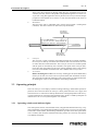
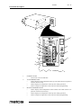
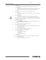
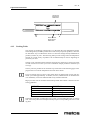
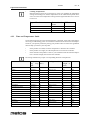
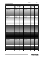
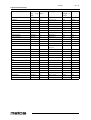
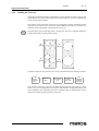
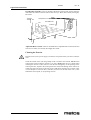
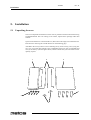
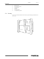
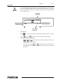
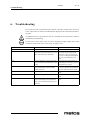
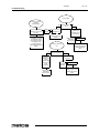
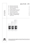
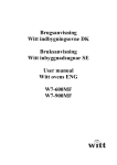
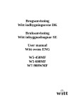
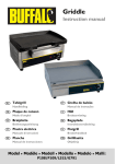
CONVEYOR OVEN
TYPE: CTX G 26
Installation and Operation Manual
S/N:
Rev.: 2.0
12.4.2002
Rev. 2.0
Dear Customer,
Congratulations on deciding to choose a Metos appliance for your kitchen activities. You
made an excellent choice. We will do our best to make you a satisfied Metos customer
like thousands of customers we have around the world.
Please read this manual carefully. You will learn correct, safe and efficient working methods in order to get the best possible benefit from the appliance. The instructions and hints
in this manual will give you a quick and easy start, and you will soon note how nice it is
to use the Metos equipment.
All rights are reserved for technical changes.
You will find the main technical data on the rating plate fixed to the equipment. When you
need service or technical help, please let us know the serial number shown on the rating
plate. This will make it easier to provide you with correct service.
For your convenience, space is provided below for you to record your local Metos service
contact information.
METOS TEAM
Metos service phone number:...............................................................................................
Contact person:....................................................................................................................
12.4.2002
Rev. 2.0
12.4.2002
Rev.
1. General .......................................................................................................... 1
1.1 Symbols used in the manual .......................................................................................... 1
1.2 Symbols used on the appliance ...................................................................................... 1
1.3 Checking the relation of the appliance and the manual ................................................. 1
2. Safety .............................................................................................................. 2
2.1 Safe use of the appliance ............................................................................................... 2
2.2 Other prohibitions (dangerous procedures) ................................................................... 2
3. Functional description .................................................................................. 3
3.1 General ..........................................................................................................................
3.2 Construction ..................................................................................................................
3.2.1 Component Location ..............................................................................................
3.2.2 Component Function ..............................................................................................
3.3 Operating principle ........................................................................................................
3.3.1 Operating switches and indicator lights .................................................................
3
3
4
4
5
5
4. Operation instructions ................................................................................. 8
4.1 Before using the appliance ............................................................................................ 8
4.1.1 Infrared Cooking Technology ................................................................................ 8
4.1.2 Heat Zoning ........................................................................................................... 8
4.1.3 Cooking Trials ....................................................................................................... 9
4.2 Operation procedures ................................................................................................... 10
4.2.1 Operation of the G-26 MenuSelect Control Oven ............................................... 10
4.2.2 Cooking in a CTX Oven ...................................................................................... 11
4.2.3 Time and Temperature Guide .............................................................................. 12
4.2.4 Loading the Conveyor ......................................................................................... 15
4.3 After use ...................................................................................................................... 16
4.3.1 Cleaning .............................................................................................................. 16
5. Installation ................................................................................................... 20
5.1 Unpacking the oven .....................................................................................................
5.1.1 Uncrating .............................................................................................................
5.2 Installation ...................................................................................................................
5.2.1 Installing Legs ......................................................................................................
5.2.2 Stacking and Mounting Two Ovens ....................................................................
5.2.3 Conveyor Belt and Temperature Display ............................................................
5.2.4 Standoffs ..............................................................................................................
5.2.5 Pivoting Heat Curtains .........................................................................................
5.2.6 Exit Tray ..............................................................................................................
20
21
22
22
22
24
24
25
25
12.4.2002
Rev.
5.3 Positioning the appliance ............................................................................................. 26
5.4 Electrical connections .................................................................................................. 26
5.5 Programming the G-26 MenuSelect Control Oven ..................................................... 27
6. Troubleshooting .......................................................................................... 29
8. Technical specifications .............................................................................. 39
12.4.2002
Rev. 2.0
General
1.
General
Carefully read the instructions in this manual as they contain important information regarding proper, efficient and safe installation, use and maintenance of the appliance.
Keep this manual in a safe place for eventual use by other operators of the appliance.
The installation of this appliance must be carried out in accordance with the manufacturer’s instructions and following local regulations. The connection of the appliance to the
electric and water supply must be carried out by qualified persons only.
Persons using this appliance should be specifically trained in its operation.
Switch off the appliance in the case of failure or malfunction. The periodical function
checks requested in the manual must be carried out according to the instructions. Have the
appliance serviced by a technically qualified person authorized by the manufacturer and
using original spare parts.
Not complying with the above may put the safety of the appliance in danger.
1.1
Symbols used in the manual
This symbol informs about a situation where a safety risk might be at hand. Given instructions are mandatory in order to prevent injury.
This symbol informs about the right way to perform in order to prevent bad results, appliance damages or hazardous situations.
This symbol informs about recommendations and hints that help to get the best performance out of the appliance.
1.2
Symbols used on the appliance
This symbol on a part informs about electrical terminals behind the part. The removal of
the part must be carried out by qualified persons only.
1.3
Checking the relation of the appliance and the manual
The rating plate of the appliance indicates the serial number of the appliance. If the manuals are missing, it is possible to order new ones from the manufacturer or the local representative. When ordering new manuals it is essential to quote the serial number shown
on the rating plate.
1
12.4.2002
Rev. 2.0
Safety
2.
Safety
2.1
Safe use of the appliance
For your safety. Do not store or use gasoline or other flammable vapors or liquids in the
vicinity of this or any other appliance.
2.2
Other prohibitions (dangerous procedures)
Using any parts other than genuine CTX factory manufactured parts relieves the manufacturer of all liability.
Improper installation, adjustment, alteration, service or maintenance can cause property
damage or major injury. Read the installation and operating instructions thoroughly before installing or servicing this equipment.
2
12.4.2002
Rev. 2.0
Functional description
3.
Functional description
3.1
General
Model G-26 ovens are:
•
•
•
•
•
3.2
Electrically heated
Heated by infrared panels
MenuSelect Operated
Conveyorized
Electronically controlled
Construction
The oven features stainless steel exterior and an aluminized steel oven chamber. The conveyor is a 40 centimetres wide stainless steel chain link belt. It is equipped with four
10 cm high adjustable legs, heat curtains, crumb trays and exit trays.
3
12.4.2002
Rev. 2.0
Functional description
3.2.1 Component Location
8
7
6
1
5
2
1.
2.
3.
4.
5.
6.
7.
8.
3
4
10 cm Adjustable Legs
Heat Curtain
Crumb Tray
Oven Data Plate, located under conveyor
Conveyor
Controls
Conveyor Motor
Control Compartment Cooling Fan
3.2.2 Component Function
1.
2.
3.
4.
4
Single and Stacked Ovens
The CTX model G-26 is available as either a single oven or two ovens stacked.
Each unit is supplied with four 10 cm adjustable legs. The legs must be used on
single oven or lower oven of stacked oven to validate the warranty.
The stacked oven is made up of two separate units, one on top of the other. Mounting pins (P/N G26STACK) must be installed when stacking two ovens, if pins are
not used warranty will be voided.
Cooking Area
The CTX Model G-26 has a 660mm long cooking deck (chamber) with a 406mm
wide conveyor belt.
Controller
The Controller controls both the temperature and conveyor belt speed (cook time)
of the oven. Cook temperature can be set to from 93°C to 509°C and cook time can
be set from 01:00 minute to 30:00 minutes.
Infrared Heating Panels
Patented heating panels are positioned above and below the conveyor belt of each
oven deck (chamber). When energized these panels emit infrared long waves.
12.4.2002
Rev. 2.0
Functional description
5.
These waves do not heat the air through which they pass. Instead the waves are absorbed by the outer surface of the product transported through the oven on the conveyor belt. Using this application food is placed on the conveyor and the unique
properties of the infrared waves cause it to cook from the outside to the center in
traditional fashion.
Heat Zones
The heat zones refer to individual areas of heat control within a cooking deck
(chamber). The deck contains two heat zones (top and bottom).
Top element
Övre element
Ylempi elementti
Top zone Övre zon Ylempi paistoalue
Bottom zone Nedre zon Alempi paistoalue
Bottom element
Nedre element
Alempi elementti
6.
7.
3.3
Conveyor
The conveyor is used to transport the product through the oven deck (chamber).
the conveyor is made up of a frame and a stainless steel wire belt which can travel
in either direction around the frame. The conveyor can travel at variable speeds
and the speed is controlled by the Controller. The speed of the conveyor determines how long the product will be in the cooking chamber which is the cooking
time. The oven chamber is 470mm wide with a 406mm wide conveyor belt.
Accessories
Kit For Stacking Two G-26’s. An accessory stacking pins kit (P/N G26STACK)
allows you to stack two G-26’s one on top of the other (See Installation section).
The pins must be used when stacking a G-26 or the warranty is voided. Instructions
for stacking the ovens are also available in the stacking bracket kit.
Operating principle
The G-26 conveyor oven employs infrared cooking technology. Infrared heat panels are
placed on above and one below the conveyor. These panels form the oven’s upper and
lower heat zones. A controller accurately maintains set cooking temperatures and conveyor speed (cooktime) for consistent and repeatable results. Food is cooked by absorption of
infrared waves as it is conveyed through the oven chamber.
3.3.1
Operating switches and indicator lights
The control panel consists of an ON/OFF switch, a keypad with multi-function keys, a liquid crystal display, a keyoperated programming lockout switch, a conveyor reversing key
switch and a circuit breaker. The following information provides a basic description of the
oven’s controls, their locations and the function they perform. It is necessary the operator
to be familiar with them.
5
12.4.2002
Rev. 2.0
Functional description
1
2
14
3
13
15
7
4
11
8
5
6
12
9
10
1.
2.
3.
6
POWER ON/OFF
•
Used to turn oven ON and OFF
TOP TEMPERATURE
•
used to display actual temperature of the top zone when used in conjunction
with the ACTUAL key.
•
used to display set temperature of the top zone during operation.
•
used to change set temperature of the top zone during programming.
BOTTOM TEMPERATURE
•
used to display actual temperature of the bottom zone when used in conjunction with the ACTUAL key.
•
used to display set temperature of the top zone during operation.
•
used to change set temperature of the top zone during programming.
12.4.2002
Rev. 2.0
Functional description
4.
5.
6.
7.
8.
9.
10.
11.
12.
13.
14.
15.
COOK TIME
•
used to display and/or change cook time setpoint of a preset menu.
ACTUAL KEY
•
used to display actual temperature of either the top or bottom zone when
used in conjunction with the TOP TEMP or BOTTOM TEMP keys.
Cursor key
•
used to move the cursor to the next digit from left to right.
Up Arrow key
•
used when programming to increase one number at a time 0 to 9 and then
roll over to 0.
Preset Menu keys 1-5
•
used to operate or program oven in one of five preset menu modes.
In the event of a power failure the oven will default back to the previously used
preset menu when power is restored. Always check that the oven is in the desired
mode when the power is restored.
MANUAL OVERRIDE
•
used to temporarily override preset menu setting and operate oven at any
desired temperature and cook time.
CLEAN
•
used to enter the self-cleaning mode of oven.
Programming Lockout Key Switch
•
used to lockout the preset menu select programmability when the key is in
the horizontal position.
Conveyor Reversing Key Switch
•
used to change the conveyor direction of travel.
Display. Provides readout of data including:
•
data being entered
•
error and service information
•
set cook times
•
set and actual temperatures
READY Light
•
when the READY light is on the oven has reached the set temperature.
Circuit Breaker Reset Switch
•
provides circuit protection. Press to reset.
7
12.4.2002
Rev. 2.0
Operation instructions
4.
Operation instructions
4.1
Before using the appliance
Before you begin to cook with your new oven you must understand the differences between cooking in it and cooking in more conventional ovens. You will produce better results if you understand the technology and follow the “rules”.
4.1.1
Infrared Cooking Technology
The technology of infrared cooking used in the CTX Gemini series ovens was first introduced by CTX in 1969. Each oven is fitted with patented infrared emitting heat panels
(heating elements). These elements form the top and bottom surfaces of the oven chamber. The G-26 has two elements, one above and one below the conveyor belt.
These elements emit infrared “long waves” which are absorbed by almost all matter in
varying degrees. Absorption of these waves by an object causes molecular agitation which
causes friction which generates heat. In this instance the object is food and the heat generated is used to cook the food. Infrared waves penetrate the outer surfaces of the food
where they are absorbed by virtually all ingredients plus the container in which the food
is placed. As a result, food cooks from the outside toward the center in very traditional
fashion.
Infrared waves, unlike conventional heat sources, do not heat the air through which they
pass, nor do they create any air currents in the oven chamber to dry out the food product.
If there is no food product in the oven the infrared waves are absorbed by the heating elements located opposite. These unique properties translate into less food waste, a more
moist product and excellent energy efficiency.
4.1.2
Heat Zoning
Since the top and bottom elements are controlled independently, they can be set anywhere
in their range. This feature offers much more versatility than many other ovens. It enables
the operator to raise only the bottom temperature to give the product a crisp hearth-baked
appearance or to cook a product evenly through a heavy metal pan. Or the operator may
choose to raise only the top element temperature to give a crisp or broiled top to a product.
It is recommended that the top and bottom temperatures be set within 24°C of each other.
Refer to the figure below. The elements are very efficient, and a temperature differential
greater than 24°C will result in the lower temperature element being heated by the higher
temperature element. This, in turn, causes an incorrect reading of temperatures and will
result in an inconsistent product.
8
12.4.2002
Rev. 2.0
Operation instructions
Top Element
Överelement
Yläelementti
24° max. differential
Max. 24° ero
Bottom element
Nedre element
Alaelementti
4.1.3 Cooking Trials
The purpose of conducting cooking trials is to determine the exact temperature settings
and cooking time(s) needed to produce best results with your specific product(s). The fastest and easiest way to conduct these trials is to start with settings already established for
product(s) similar to yours. The following table provides average time and temperature
settings for a wide variety of products. We recommend they be used as beginning set
points for your tests.
Testing can be completed easier and faster and with less confusion if you keep accurate
records of each test. To assist you we have included a sample product test form that you
can copy.
Choose your first product for test and look it up in the table on the following pages. Now
program the oven with the temperatures and cook times shown.
If you are starting the oven from “cold” please allow 45 minutes heat up time. The elements cycle after approximately 15 minutes, however, additional time is needed for the
oven chamber(s) to become stabilized and evenly saturated with heat.
Begin your first trial run. Examine the finished product and evaluate it based on the following guidelines.
RESULTS
SOLUTION
Outside too dark or burned
Reduce Temperatures
Outside too light or not cooked
Increase Temperatures
Inside Overdone or dried out
Shorten Cooking Time
Inside Underdone or raw
Lengthen Cooking Time
Sometimes an increase in temperature may require a corresponding decrease in cooking
time. Conversely a decrease in temperature may require a corresponding increase in cooking time.
9
12.4.2002
Rev. 2.0
Operation instructions
After evaluating the results, make the indicated time/temperature setting adjustments and
allow about 15 minutes for the oven to stabilize at the new temperature settings. It may be
necessary to run several tests before you obtain the exact results you want. Be sure to document each test in the “Product Test Record” below so you can ultimately produce a cooking chart for your specific items.
Product
4.2
State
Temp.
Setting
Top/Bott
Cook
Time
(Min.)
Pan Type Amount
Cooking
and Size
(Weight or result
Count)
Operation procedures
4.2.1 Operation of the G-26 MenuSelect Control Oven
1.
2.
3.
Turn oven deck ON
Turn ON main disconnect switch at the wall box.
Turn ON/OFF switch ON.
To program a new preset menu selection
Perform the procedure described in Programming the G-26 MenuSelect Control
Oven section.
At least one menu selection MUST be programmed before the oven can be operated.
To choose a preset menu selection
Press
4.
(or any other preset menu key 1-5). The display will read P--#. The
number in the display (# is shown above) will match the menu key that was pressed
(1-5). Wait for the READY light to illuminate. The light will illuminate after both
heating zones reach their set temperatures. Load the product onto the conveyor.
Manual Override Operation
This feature is used to operate the oven manually. The oven is taken out of the
menu select mode by entering new parameters and is returned to the menu select
mode without saving the parameters. Press
key. P--# (flashing) will be dis-
played. Set oven temperature and cooktime using the steps in Programming the G26 MenuSelect Control Oven section. Oven will function as set but settings will not
be saved. Display will flash on and off while the oven is in the manual override
mode. To cancel the temporary menu selection, press any preset menu key or disconnect electrical power to the oven.
10
12.4.2002
Rev. 2.0
Operation instructions
5.
To view the set temperatures
Press either
6.
key first and either
key next. The top or bottom ac-
key. The cook time will be displayed for 5 seconds. First two digits
shows the minutes (00 to 30) and the last two digits the seconds (00 to 59).
Cleaning operation
Press and hold
9.
key or
tual temperature will be displayed for 5 seconds.
To view the cook time
Press
8.
. The top or bottom set temperature will be displayed
for 5 seconds.
To view actual temperatures
Press
7.
or
key until CLn appears on the display. Machine will remain
in cleaning mode for 60 minutes.
Cancel cleaning operation
Press and hold
key until CLn disappears. Oven deck will return to preset
menu that was used previous to cleaning.
4.2.2 Cooking in a CTX Oven
Cooking in a CTX infrared conveyor oven is different than cooking in any other type of
oven including microwave ovens. Because of these differences there are some “rules” that
must be considered.
•
•
•
Continuous “Flow” Operation
CTX ovens perform best in a continuous type of operating environment. They are
not well suited to a batch type operation. Greatest efficiency is attained when as
many steps as possible in the operation are put into a continuous “flow” pattern.
Pans
The type of vessel used to hold the food has a bearing on cooking time and consistency of results.
1.
Pans with a dull black finish absorb maximum infrared heat. Product cooks
faster in dull black pans than in shiny silver ones.
2.
Heavier (thicker gauge) pans cook more evenly. They heat slower but hold
their heat longer. Lighter (thinner gauge) pans transfer heat faster but less
evenly. They also cool faster.
Product
Best results are obtained when product entering the oven is consistent.
1.
Food portions entering the oven should all be approximately the same temperature. When food portions entering the oven vary in temperature, the
temperature of those portions coming out of the oven, though cooked, will
also vary.
2.
Product size should be the same. If product is 13mm thick one time and
19mm thick next, cooking results will be different.
3.
Product loading density also affects results. If portion size and pan size are
the same, two portions per pan will cook differently than ten portions per
pan.
11
12.4.2002
Rev. 2.0
Operation instructions
•
4.2.3
Cooking Temperatures
Because infrared waves do not heat the air in the oven chamber the temperature
settings and readings are surface temperatures of the infrared heat panels themselves. For this reason temperature settings will be higher than those for a conventional oven.
Type of Product
Conventional
Oven
CTX Oven
Bakery Products
149-176°C
232-287°C
Pizza, Casseroles, Flat Meats, etc.
176-260°C
315-398°C
Broiled Fish, Steaks etc.
260-287°C
398-454°C
Time and Temperature Guide
On the following pages are times and temperatures, remember, these times and temperatures only provide starting points. You will have to determine the exact times and temperatures for your specific products by testing your products. Here are some basic guidelines
that will help you choose your set points.
•
•
•
If the product is too dark, lower the temperature or decrease the cook time.
If the product is too light, raise the temperature or increase the cook time.
If the outside of the product is done to your satisfaction but the internal temperature is not hot enough, then increase the cooktime.
Increasing cooktime may require a corresponding decrease in temperature.
Product
Temp Set- Cook time Pan Type and Size Amount
State
ting Top/ (Min.)
(weight or
Bott
count)
Appetizers
Nachos
454/454°C
3.0
Alum. 25 cm
280g
Fresh
Oyster Rockefeller
509/509°C
4.0
Alum.
6-8
Fresh
Potato Skins
454/454°C
3.0
Alum. 25 cm
280g
Fresh
Rumaki
454/454°C
6.0
Alum.
6-8
Fresh
Seafood Kabob
509/509°C
6.0
Alum. 15 cm
110-170g
Fresh
Bagels
398/398°C
8.0
Wire Mesh
85g
Fresh
Bread Sticks
454/454°C
6.0
Alum. 1/2 size
55g
Fresh
Brown & Serve Rolls
370/370°C
4.0
Alum.
28g
Thawed
Corn Bread
315/315°C
15.0
Alum. 1/2 size
1.1kg
Fresh
Dinner Rolls
370/370°C
8.0
Alum. 1/2 size
85g
Fresh
Fresh Bread
370/370°C
10.0
Alum. Sheet
0.45kg
Fresh
Garlic Bread
482/482°C
2.0
Alum. 1/2 size
0.45kg
Fresh
Muffins
315/315°C
15.0
Dark Alum.
85g
Fresh
Popovers
287/287°C
30.0
Dark Alum.
85g
Fresh
Soft Pretzels
426/426°C
8.0
Alum. 1/2 size
55g
Fresh
Toast
482/482°C
2.0
None
Slice
Fresh
Baked Goods
12
12.4.2002
Rev. 2.0
Operation instructions
Product
Temp Set- Cook time Pan Type and Size Amount
State
ting Top/ (Min.)
(weight or
Bott
count)
Beef
Beef Ribs (Finish)
509/454°C
8.0
Alum. 1/2 size
8 ribs
Precooked
Hamburger 4/1
509/509°C
4.0
Alum. 1/2 size
110g
Fresh
Hamburger 4/1
509/509°C
6.6
Alum. 1/2 size
110g
Frozen
Hamburger 2/1
509/509°C
10.0
Stainless
220g
Fresh
Liver & Onions
454/454°C
10.0
Alum. 1/2 size
110g
Fresh
Meatballs
482/482°C
8.0
Alum. 1/2 size
55g
Refrig.
Rib Eye Steak
509/509°C
8.0
Stainless 4x7
280g
Fresh
Salisbury Steak
482/482°C
6.0
Alum. 1/2 size
110g
Fresh
Strip Steak
509/509°C
8.0
Stainless 4x7
220g
Fresh
Strip Steak
509/509°C
10.0
Stainless 4x7
340g
Fresh
Tenderloin, Whole
454/454°C
15.0
Alum. 1/2 size
1,8kg
Fresh
Bacon
482/482°C
6.0
Alum. w/Rack
0.45kg
Refrig.
Biscuits
426/426°C
8.0
Alum. 1/2 size
1.35kg
Fresh
Breakfast Foods
Egg Patty
398/398°C
4.0
Alum. 12 cm
2 eggs
Fresh
Fried Eggs
398/398°C
4.0
Alum. 12 cm
2 eggs
Fresh
Puffy Omelet
398/398°C
8.0
Alum. Skillet 22 cm
170g
Fresh
Quiche
370/370°C
25.0
Dark. Alum. Pie
680g
Fresh
Sausage, Link
482/482°C
6.0
Alum. 1/2 size
42g
Refrig.
Sausage, Patty
482/482°C
4.0
Alum. 1/2 size
42g
Refrig.
Enchiladas
482/482°C
8.0
Oven China
340g
Refrig.
Lasagna
454/454°C
12.0
Oven China
340g
Refrig.
Macaroni & Cheese
370/370°C
25.0
Stainless 12x20
2.25kg
Refrig.
Pasta & Sauce
454/457°C
8.0
Oven China
340g
Refrig.
Casseroles
Cookies
Bar Cookies
343/343°C
10.0
Alum. 1/2 size
0.45kg
Fresh
Brownies
370/370°C
15.0
Alum. 1/2 size
1.6kg
Fresh
Chocolate Chip
343/343°C
7.00
Alum. 1/2 size
20g
Fresh
Chocolate Chip
343/343°C
8.00
Alum. 1/2 size
15g
Fresh
Macaroons
343/343°C
15.0
Alum. 1/2 size
28g
Fresh
Oatmeal
343/343°C
7.0
Alum. 1/2 size
42g
Fresh
Baked Apple
370/370°C
25.0
Stainless 12x20
12 apples
Fresh
Baked Custard
370/370°C
25.0
Custard Dish in 1/2 size 110g
pan
Fresh
Cream Puffs
287/287°C
30.0
Alum. 1/2 size
55g
Fresh
Fruit Pie
287/287°C
30.0
25 cm Pie
740g
Fresh
Fruit Pie
287/287°C
50.0
25 cm Pie
740g
Fresh
Layer Cake
343/343°C
15.0
Alum. 1/2 size
1,35kg
Fresh
Desserts
13
12.4.2002
Rev. 2.0
Operation instructions
Product
Temp Set- Cook time Pan Type and Size Amount
State
ting Top/ (Min.)
(weight or
Bott
count)
Meringue Pie
343/343°C
7.0
25 cm Pie
740g
Fresh
Puff Pastry
343/343°C
15.0
Alum. 1/2 size
110g
Thawed
Filet of Sole
509/509°C
6.0
Stainless 4x7
170g
Fresh
Lobster Tail
509/509°C
8.0
Stainless 4x7,w/water
225g
Fresh
Sea Scallops
509/509°C
6.0
Stainless 4x7
225g
Fresh
Shrimp Scampi
509/509°C
6.0
Stainless 4x7
225g
Fresh
Fish & Seafood
Snow Crab
509/509°C
6.0
Stainless 9x11
225g
Fresh
Stuffed Flounder
509/509°C
8.0
Stainless 4x7
225g
Fresh
White Fish Fillet
509/509°C
8.0
Stainless 4x7
225g
Fresh
Whole Trout
509/509°C
8.0
Stainless 9x11
255g
Fresh
Deep Dish
398/398°C
10.0
Black Deep Pan
Fresh
Calzone
357/357°C
8.0
Pizza Screen or Black
Sheet Pan
Fresh
Pizza
Stuffed
343/343°C
20.0
Black Deep Pan
Fresh
Thick Crust
412/412°C
6.5
Black Pizza Pan
Fresh
Thin Crust
426/426°C
5.5
Pizza Screen
Fresh
Thin Crust
343/343°C
9.0
Pizza Screen
Fresh
Thin Crust
426/426°C
5.0
Pizza Screen
Pre-bake
Breaded Chop
426/426°C
8.0
Alum. 1/2 size
110g
Precooked
Pork Chops
426/426°C
15.0
Alum. 1/2 size
110g
Fresh
Pork Ribs (Finish)
509/509°C
8.0
Alum. 1/2 size
Slab
Precooked
Chicken Cordon Bleu
426/426°C
15.0
Alum. 1/2 size
12 pcs.
Fresh
Chicken Pieces
426/426°C
18.0
Alum. 1/2 size
12 pcs.
Fresh
Half Chicken
426/426°C
20.0
Alum. 1/2 size
0,56kg
Fresh
Whole Chicken
426/426°C
25.0
Alum. 1/2 size
1,15kg
Fresh
Pork
Poultry
14
12.4.2002
Rev. 2.0
Operation instructions
4.2.4
Loading the Conveyor
Achieving maximum production is dependent on proper utilization of the conveyor belt.
Depending on size, pans can be placed on the conveyor belt in a variety of configurations
to best use the space available.
Figure below shows placement of various size round pans to achieve maximum production rates. Pans in other sizes or shapes will require different placement. You will have to
determine the best placement configuration for your pans.
DO NOT place pans off the edge of the conveyor belt. The pans could fall spilling the
product and possibly causing personal injury.
6"
15 cm
12"
30 cm
8"
20 cm
14"
36 cm
Production output for any pan size can be easily calculated using the following formula:
Length
of Oven
Chamber
(cm)
:
Cooktime
(Min.)
:
Pan Length
(cm)
x
60 Min.
Per Hour
=
Horly
Production
Rate per
Conveyor
This formula is based on a succession of single pans being placed on the belt. No consideration is given to multiple pan across the 16” wide belt nor to staggered loading. The
hourly production rate obtained by the above calculation must be multiplied by a factor
equal to the number of pans placed across the belt.
15
12.4.2002
Rev. 2.0
Operation instructions
Cooktime
ROUND PAN
*203
229
Sheet Pan
*127
*152
*178
254
279
305
330x457
1 min.
312
260
223
195
173
156
142
130
2 min.
156
130
11
98
87
78
71
65
3 min.
104
87
74
65
58
52
47
43
29
4 min.
78
65
56
49
43
39
35
32
22
5 min.
62
52
45
39
35
31
28
26
17
6 min.
52
42
37
33
29
26
24
22
14
7 min.
45
37
32
29
25
22
20
19
12
8 min.
39
33
29
24
22
20
18
16
11
9 min.
35
29
25
22
19
17
16
14
9
10 min.
31
26
22
20
17
16
14
13
9
11 min.
28
24
20
18
16
14
13
12
12 min.
26
22
19
16
14
13
12
11
13 min.
24
20
17
15
13
12
11
10
14 min.
22
18.5
16
14
12
11
10
9
15 min.
21
17
15
13
11.5
10
9.5
8.5
16 min.
19.5
16
14
12
11
10
9
8
17 min.
18
15
14
11.5
10
9
8
7.5
18 min.
17
14.5
12.5
11
9.5
8.5
8
7
19 min.
16.5
14
12
10
9
8
7.5
7
20 min.
15.5
13
11
10
8.5
8
7
6.5
* These pans may be placed side by side on the belt, doubling the capacity.
All product to be prepared on the G26 requires that some product be run through the oven
on a trial basis to determine what times and temperatures are best suited to each specific
product. (See Time and Temperature Guide sections chart which provides reference
points for you to start. You will then have to adjust either the time or the temperature to
fit your product.)
4.3
After use
4.3.1
Cleaning
Frequent cleaning will help your oven operate at peak performance and efficiency. Keep
your oven clean!
Cleaning the Cooling Fan Filter
The foam filter and protective grill of the cooling fan should be cleaned weekly. Refer to
the figure below. Daily cleaning may be required if flour has built up on filter. Snap the
protective grill off and wipe clean with a cloth. Remove the foam filter and inspect it. If
16
12.4.2002
Rev. 2.0
Operation instructions
the filter appears dusty, shake briskly. If it is greasy, wash in warm soapy water, rinse,
squeeze and set aside to dry completely. Reinstall filter and grill.
BE SURE filter is dry before reinstalling. Electrical components are directly below the
cooling fan.
Cleaning the Oven Chamber
The G-26 has a self-cleaning mode. The cleaning operation procedure is outlined below.
Do not reach into hot oven. Severe burns could result. Be sure oven is off and cool to the
touch and the conveyor is stopped before attempting to wipe out the oven chamber.
After the oven has cooled, any residue remaining in the oven can be removed by reaching
in and wiping out the oven chamber before entering the cleaning mode.
Cleaning operation: Press and hold
key until CLn appears on the display. Ma-
chine will remain in cleaning mode for 60 minutes.
Cancel cleaning operation: Press and hold
key until CLn disappears. Oven deck
will return to preset menu that was used previous to cleaning.
17
12.4.2002
Rev. 2.0
Operation instructions
Cleaning “Loose” Parts
Commercial oven cleaners can be used to clean stainless steel “loose” parts.
The following items must be removed from the oven to be cleaned manually in the pot
sink.
These procedures should be performed only when the on is OFF, cool to the touch and the
conveyor is stopped.
Crumb Trays: Clean daily. Lift the belt and remove the crumb trays from both entrance
and exit end of each conveyor. Empty residue, wash, rinse and dry thoroughly. Re-install.
Exit Trays: Clean daily. Remove exit tray by lifting up and out, empty residue, wash,
rinse and dry thoroughly. Reinstall.
18
12.4.2002
Rev. 2.0
Operation instructions
Pivoting Heat Curtains: Clean as needed. Unhook the pivoting heat curtains from the
rods above the entrance and exit ends of each conveyor. Wash, rinse and dry thoroughly.
Re-install.
Adjustable Heat Curtains: Clean as needed. Remove adjustable heat curtains from each
end of oven. Wash, rinse and dry thoroughly. Re-install.
Cleaning the Exterior
Disconnect the oven’s power supply cord from its receptacle before you start to clean the
oven.
Clean the outside of the unit using a damp cloth or stainless steel cleaner. Do not clean
control panel with an abrasive cleanser. Use only a damp cloth. Be very careful when
cleaning the unit not to allow water to enter the unit through any of the openings in the
control panel box. Liquid in the control panel area could cause damage to the controls or
could cause electrical shorts in the unit which could shock someone. Do not allow water
or water droplets to enter into the: a) fan filter, b) louvers on the side of the oven, c) area
behind the control panel, or d) operating controls.
19
12.4.2002
Rev. 2.0
Installation
5.
Installation
5.1
Unpacking the oven
The oven components should be moved as close as possible to final location before being
assembled/stacked. The oven setting on its bottom, requires door openings wider than
679mm.
Open carton and remove it from around oven, then remove the empty carton from the area.
Directions for removing the wooden skid are on the following page.
Attached to the conveyor belt is a box containing one (1) short exit tray, one (1) long exit
tray, two (2) pivoting heat curtains, four (4) adjustable 10cm legs, four (4) standoffs and
two (2) sets of keys. (See the figure below). Check to make sure you received the correct
quantity of parts.
1
2
3
6
4
5
20
12.4.2002
Rev. 2.0
Installation
1.
2.
3.
4.
5.
6.
Short Exit Tray
Pivoting Heat Curtains
Long Exit Tray
Standoffs
Two Sets of Keys
4” Adjustable Legs NSF
5.1.1 Uncrating
Lay the oven on its front side then remove the four (4) bolts attaching wooden skid to bottom of oven.
21
12.4.2002
Rev. 2.0
Installation
5.2
Installation
5.2.1 Installing Legs
Install the four 4” adjustable legs as shown in the figure below then lift the oven onto it’s
legs. On single oven installation place the oven in it’s permanent position.
5.2.2
Stacking and Mounting Two Ovens
A stacking pins kit (Kit # G26STACK) is required when stacking two ovens.
1.
2.
3.
22
Move the lower oven (oven with legs installed) to it’s permanent position. Remove
the two plug buttons, one located in each rear top corner hole of lower oven.
Unpack the upper oven. Locate the two (2) stacking pins in the kit. Install the two
pins into the two bottom rear threaded holes of the upper oven. These are the holes
normally used for the rear legs.
Using four people lift the upper oven on top of the lower oven. Align the stacking
pins as shown in the figure below with the holes in the top of the lower oven and
lower the oven into place.
12.4.2002
Rev. 2.0
Installation
Stacking pins in upper oven
Tappar i den övre ugnen
Tapit ylemmässä uunissa
Holes in lower oven
Hålen i den nedre ugnen
Reiät alemmassa uunissa
4.
Once the ovens are stacked and secured check to make sure the oven(s) are level.
Adjust the legs if necessary as shown in the figure below.
23
12.4.2002
Rev. 2.0
Installation
5.2.3
Conveyor Belt and Temperature Display
The conveyor belt is designed to travel in either direction using the conveyor Reversing
Key Switch. The temperature display may be set for either °F or °C. Your Certified Installer will set both of these functions for you during the installation. If you require a
change in the degrees display (Fahrenheit or Centigrade) in the future call your local Authorized Service Agency.
5.2.4 Standoffs
If the back side of the oven will be against a wall the four (4) standoffs supplied in the
installation kit must be mounted to the rear panel of oven. To install the standoffs remove
one rear panel screw at a time and replace with a standoff as shown in the figure below.
These standoffs will keep the ventilation louvers on the rear control compartment panel
from being blocked.
Placing the oven directly against a wall without the standoffs will block the vent louvers
and will not allow hot ambient air in the control compartment to escape. The compartment
would then overheat and cause possible damage to electrical components.
Leave at least 50 mm space between the oven and the back wall.
24
12.4.2002
Rev. 2.0
Installation
5.2.5
Pivoting Heat Curtains
The oven is shipped with adjustable heat curtains attached to the oven and pivoting heat
curtains are also supplied with the oven. To use the pivoting heat curtains first remove adjustable heat curtains and then install the pivoting heat curtains by hanging them on the
steel rod as shown in the figure below.
5.2.6
Exit Tray
Next install the desired exit tray at the exit end of the conveyor. Two exit trays are supplied with each oven, one short and one long as shown in the figure below.
25
12.4.2002
Rev. 2.0
Installation
5.3
Positioning the appliance
Some very important considerations must be made when choosing the place where the
oven is to operate.
1.
2.
3.
5.4
This oven is conveyorized and operates continuously. It should be placed so it fits
into the “flow” of the operation.
Drafts entering the oven chambers can cause inconsistent cooking results. Check
the area surrounding the oven and eliminate sources of drafts such as open windows or doors and fans or other appliances that cause air circulation.
Oven should be positioned so hot air from another piece of equipment cannot enter
oven cooling fan air intake on the control compartment. Serious problems could
occur.
Electrical connections
All wiring and electrical connections required for the oven(s) must be performed by a certified electrician. Each oven must be wired according to the electrical specifications for
the oven rating. G-26 demands 220/380 VAC, 50 Hz 3 phase power supply.
All G-26 ovens have been manufactured to operate in certain voltage.
Check ALWAYS the correct operating voltage from the data plate before installing the
oven. Incorrect voltage may damage the oven immediately.
If the tolerance of operating voltage is too low for certain voltage on the data plate, the
oven may function improperly.
Consult all applicable national and local codes for further electrical connection requirements. Input wire must be at least 10 mm and electrician must use protected cable.
Each oven must have an overcurrent protection in installation (not supplied). Main overcurrent protection must have 3 mm clearance between all swithes in open position.
Check the data plate before installing. Connection must be done according to oven’s data
plate.
Oven must be ground connected according to present IEC/CEE regulations and local orders.
Input wire must be protected or in conduit. Each oven must be ground connected with a
separeate ground wire. Conduit may not be used as ground.
Electrical connections must correspond to present IEC/CEE and local regulations. Connections must be verified by authorized electrician before operation.
Electrician should follow installation instructions. Joints to smoke removal, electrical
connectors and oven’s first start-up must be done by an authorized agent.
Refer to Operation instructions section.
26
12.4.2002
Rev. 2.0
Installation
Overcurrent protector must be in OFF position and oven disconnected from power supply
when removing or servicing the appliance. Professional should disconnect the oven from
its power supply.
5.5
Programming the G-26 MenuSelect Control Oven
The oven controller controls all functions of the oven. To operate the oven the controllers
must be programmed. The following pages contain a step by step “hands on” programming exercise. We invite you to actually program your oven by following examples.
This exercise assumes first time start after installation. Programming from factory is 93°C
temperature settings and 2 minute cook times.
1.
2.
Turn Oven Deck ON
Turn ON the main disconnect switch at the wall box.
Place the key into the slot in the control board located below the keypad and turn
it to the vertical position.
Press ON/OFF rocker switch to ON position. Oven will startup in a preset default
of 93°C for top and bottom zones and at a 2 minute cook time. Control will display
- - - -. You are now ready to proceed with programming.
Choose a menu selection to program
Press and hold
3.
key (or any other preset menu key 1-5) until P-- # appears in
the display and begins to flash. The number in the display (# is shown above) will
match the menu key that was pressed (1-5).
Set top temperature
Press
key. The current top set temperature appears in the display.
Press
and
•
Pressing
keys as necessary to change the displayed temperature.
key once increases the “active” (flashing) digit by one. This
digit “rolls over” to its minimum value if the key is pressed when the digit
shows its maximum value.
•
4.
Pressing
key once causes the next digit to the right to become “ac-
tive” (flashing) digit. If the far-right digit is flashing when the key is
pressed, the far-left digit will flash and become the “active” digit.
Set bottom temperature
Press
key. The current bottom set temperature appears in the display.
Press
key and
key as necessary to change the displayed temperature.
27
12.4.2002
Rev. 2.0
Installation
It is recommended that the temperatures of the top and bottom zones be set WITHIN 24°C OF EACH OTHER. Greater temperature differences may result in the
hotter zone heating the cooler zone. This may cause inconsestent cooking results.
See the figure below..
Top Element
Överelement
Yläelementti
24° max. differential
Max. 24° ero
Bottom element
Nedre element
Alaelementti
5.
6.
Set cook time
Press
key. The current cook time appears in the display (minutes : seconds).
Press
key and
key as necessary to change the displayed time.
Press ONE of the following keys:
•
,
or
: Re-enter the top setpoint temperature, bottom set-
point temperature, or cook time.
•
Any other key except
or
: Resume operation, but leave Pro-
gramming Mode active. Other Preset Menu Selections can be programmed
at this time.
28
12.4.2002
Rev. 2.0
Troubleshooting
6.
Troubleshooting
Error codes are used in troubleshooting to indicate a possible problem and/or corrective
action. These codes are shown in the MenuSelect display and are explained in the following chart.
An authorized service representative must be contacted for any failures that cannot be
remedied by reprogramming.
Do not remove access panel at rear of control compartment. High voltage exists inside
compartment which can cause serious injury or danger to life.
DISPLAYED ERROR CODE
EXPLANATION
CORRECTIVE ACTION
E-00
Programming selections lost
Re-enter MenuSelect programs
E-01
High ambient Condition. Temperature in- Check axial cooling fan at top of conside control enclosure exceeds 65°C. Oven trol box for proper operation and
shuts down and beeps continuously.
cleanliness. If fan is not running or
oven stays in the high ambient mode
call your local authorized service
agent.
E-02
Conveyor Runaway. Conveyor runs full Check for proper speed setting. If
speed. Oven shuts down and beeps contin- speed setting is correct call your local
uously.
authorized service agent.
E-04
Conveyor Jammed. Conveyor stopped
when speed setting is between 01:00
minute and 30:00.
Clear item that is jammed conveyor.
If conveyor still does not operate call
your local authorized service agent.
E-35
Top Heating Zone Failure
Call your local authorized service
agent.
E-36
Bottom Heating Zone Failure
Call your local authorized service
agent.
E-40
Heating Zone Temperature High Limit.
One or both heating zones greater than
526°C. Oven shuts down and beeps continuously.
Call your local authorized service
agent.
29
12.4.2002
Rev. 2.0
Troubleshooting
Oven is dark
Conveyor runs full
speed or
uncontrollably
No
Did oven circuit
breaker trip?
Located next to
control panel.
Plug in No Is power cord
oven.
plugged in?
Check your cooktime
setting. It may be set
too fast.
Yes
Check main circuit
breaker
If cooktime is correct
turn ON/OFF switch
OFF and then ON. If
belt speed is still
incorrect call your
local authorized service
agent.
If cooktime
setting is at
30:00
minutes belt
may appear
to be
stopped.
Call your local
authorized
service agent.
Is circuit breaker on
front panel tripped?
Yes
No
Call your local
authorized
service agent.
Conveyor does not
run
No
30
Is there power to Yes
oven?
Reset breaker.
If breaker continues
to trip call your local
authorized service
agent
Yes
Is conveyor belt
jammed
Yes
Free jam
and reset
breaker.
No
Reset breaker.
If breaker continues
to trip call your local
authorized service
agent
12.4.2002
Rev. 2.0
Technical specifications
8. Technical specifications
Wiring diagram
Installation drawing
Technical specifications table
39
Wiring diagram
3
L1
L2
L3
Current (A)
RFI Filter
Radiotaajuinen suodatin
N
Relay
Relä
Rele
Grounding
Jord
Maadoitus
T/C30
T/C31
Top left
Top right
Övre vänster Övre höger
Ylä vasen
Ylä oikea
T/C32
Bottom left
Nedre vänster
Ala vasen
P.C. Board
P.C. kretskort
Näppäinohjauskortti
Control transformer, 12V
Kontrolltransfomator, 12V
Ohjausmuuntaja, 12V
Black
Svart
Musta
Grounding
Jord
Maadoitus
Motor Transformer, 32V
Kontrolltransfomator, 32V
Ohjausmuuntaja, 32V
Black/white
Svart/vit
Musta/valk.
MODEL G-26 ELECTRICAL SCHEMATIC, 380-400 V, 3 Ph, 50 Hz
MODEL G-26 KOPPLINGSSCHEMA, 380-400 V, 3 Ph, 50 Hz
MALLIN G-26 KYTKENTÄKAAVIO, 380-400 V, 3 vaihetta, 50 Hz
Motor
Motor rever- Moottorin
suunnanreversing seringskoppling
vaihtokytkin
key
Red, röd, punainen
Output, utgång, ulostulo
Grn, jord, maad
Black, svart, musta
Bottom, nedre, ala
Var.
Var.
Coil
Hi-limit
Överhettn.skydd Spole
Kela
Ylik.suoja
Fan
Fläkt
Puhallin
Element (bottom, nedre, ala)
Element (top, övre, ylä)
Top, övre, ylä
Motor sensor
Moottorin anturi
Relay
Relä
Rele
Relay
Relä
Rele
Circuit breaker
Strömbrytare
Virtakytkin
Grounding
Jord
Maadoitus
On/Off switch
On/Off brytare
On/Off -kytkin
6,4 kW 0,1 14,0 13,8 13,9
Phase Total
kW
Filter's switchboard
Spänningsfilter
Jännitesuodatin
380-400
Volts
Grounding
Jord
Maadoitus
380 VAC
T/C33
Bottom right
Nedre höger
Ala oikea
Lockout key switch
Avbrytarnyckelkoppling
Avainlukon kytkin
12.4.2002
Rev. 2.0
Technical specifications
Installation drawing
Single oven on legs
Enkel ugn med fötter
Yksikerroksinen uuni jaloilla
Belt 406mm
Trasportörband 406mm
Liukuhihna 406mm
Stacked double oven on legs
Dubbelugn med fötter
Kaksikerroksinen uuni jaloilla
41
12.4.2002
Rev. 2.0
Technical specifications
Item
Specification
Conveyor belt width
406 mm
Heating zone dimensions
470mm x 660mm x 108mm
Conveyor baking area
0,27 m2
Overall dimensions - single oven on legs
1156mm x 679mm x 457mm
Overall dimensions - Two ovens stacked using 1156mm x 679mm x 813mm
the G26STACK kit and mounted on legs
42
Net weight of single unit
94 kg
Shipping weight of single unit
118 kg
Shipping dimensions
1270mm x 787mm x 559mm
Average operating kW
8,1 kW
Allowable temperature ranges
93°C-482°C
Cook time
Adjustable 1-30 min
Insulation
51 mm on all sides
Heat source
2 emitters/oven
Oven chamber steel
Welded and reinforced 16 gauge aluminized steel
Outer body steel
18 gauge stainless steel