1
INSTALLER MANUAL
VER. B
Installer Manual
1
Customer Information
1.
2.
3.
4.
5.
6.
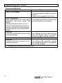
The ORBIT-6 (Model RP-206) complies with FCC Part 68 Rules. On the upper panel of this
product is a label that contains, among other information, the FCC Registration Number and
Ringer Equivalence Number (REN is 0.8B). If requested, this information must be provided to the
Telephone Company.
An FCC compliant telephone connector is provided with this equipment. This equipment is
designed to be connected to the telephone network or premises wiring using a connector, which
is Part 68 compliant.
If the ORBIT-6 (RP-206) is not operating properly, it may cause harm to the telephone network. If
so, the Telephone Company will notify you in advance that a temporary discontinuance of service
may be required. If advance notice is not practical, you will be notified as soon as possible. Also,
you will be advised of your right to file a complaint with the FCC if it is necessary.
The Telephone Company may make changes in its facilities, equipment, operations, or
procedures, which could affect the operation of the equipment. If this happens, the Telephone
Company will provide advance notice in order to enable you to make the necessary modifications
to maintain uninterrupted service. If the equipment is causing harm to the telephone network, the
Telephone Company may request that the equipment be disconnected until the problem is
resolved.
Connection to telephone company-provided coin service is prohibited. Connection to party line
service is subject to state tariffs.
If trouble is experienced with the ORBIT-6 (RP-206), for repair and warranty information, please
contact your supplier.
For service centers please see back cover.
FCC Warning
This equipment has been tested and found to comply with the limits for a Class B digital device
pursuant to Part 15 of the FCC Rules. These limits are designed to provide reasonable protection
against harmful interference in a residential installation. This equipment generates, uses, and can
radiate radio frequency energy and, if not installed and used in accordance with the instructions, may
cause harmful interference to radio communications. However, there is no guarantee that interference
will not occur in a particular installation. If this equipment does cause harmful interference to radio or
television reception, which can be determined by turning the equipment off and on, the user is
encouraged to try to correct the interference by one or more of the following measures:
• Reorient or relocate the receiving antenna.
• Increase the separation between the equipment and the receiver.
• Connect the equipment into an outlet on a circuit different from that to which the receiver is
connected.
• Consult the dealer or an experienced Radio/TV technician for help.
Changes or modifications to this unit not expressly approved by Rokonet, Ltd., could void the user's
authority to operate the equipment.
This equipment has been approved to Council decision 98/482/EC – “TBR 21” for pan-European single
terminal connection to the Public Switched Telephone Network (PSTN). However, due to differences
between the individual PSTNs provided in different countries, the approval does not, in itself, give an
unconditional assurance of successful operation on every PSTN termination point.
In the event of problems, you should contact your equipment supplier in the first instance.
2
Installer Manual
Copyright © 2001
by Rokonet Ltd.,
14 Hachoma Street
Rishon Letzion 75655
Israel
All rights reserved.
No part of this document may be reproduced in any form without prior
written permission from the publisher.
5IN206IM B
Installer Manual
3
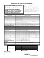
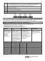
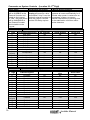
Summary of User’s Commands
It is necessary to ARM your system to
obtain protection from intrusion.
All other forms of protection,
including fire and 24-hour panic
alarms (i.e. police, fire, and medical)
are always ready to report alarms
and do NOT need to be armed.
FUNCTION
This page, called a Command
Summary, is intended to give you
brief summaries of common
system operations. More detailed
explanations and related
information can be found within, by
referring to the user manual.
PROCEDURE
System Arming
Stay Home Arming
Instant Stay
System Disarming
Duress Disarming
Silencing an Alarm
Bypassing / Unbypassing a
Zone
Quick Bypassing Zone
[USER CODE] + [ARM]
[USER CODE] + [STAY]
[STAY] + [STAY]
[USER CODE]
[DURESS CODE]
[USER CODE]
[ Q ] + [ 1 ] + [USER CODE ] + [ ZONE NUMBER TO BE
BYPASSED / UNBYPASSED]
[ ZONE NUMBER TO BE BYPASSED ] for at least 2 seconds
[ Q ] + [ 2 ] + [USER CODE ] + [UTILITY OUTPUT NUMBER
Reset Smoke Detector(s)
which is responsible for resetting the Smoke Detector]
Utility Output Operation
[ Q ] + [ 2 ] + [USER CODE ] + [ UTILITY OUTPUT NUMBER ]
Display Troubles
[Q]+[3]
Display Memory
[Q]+[4]
Setting/Changing
[ Q] + [ 5 ] + [MASTER CODE] + [CODE NUMBER TO BE
a User Code
SET/CHANGED] + [NEW CODE]
Set Date
[ Q ] + [ 6 ] + [ 1 ] + [MASTER CODE] + [MM] [DD] [YY]
Set Time
[ Q ] + [ 6 ] + [ 2 ] + [MASTER CODE] + [H][H] [M][M]
*Set Auto Arm Time
[ Q ] + [ 6 ] + [ 3 ] + [MASTER CODE] + [H][H] [M][M]
Set Follow-Me Phone No. 1 [ Q ] + [ 7 ] + [ 1 ] + [MASTER CODE] + Phone No. + [ #]
Set Follow-Me Phone No. 2 [ Q ] + [ 7 ] + [ 2 ] + [MASTER CODE] + Phone No. + [ #]
**Set Follow-Me Phone No. 3 [ Q ] + [ 7 ] + [ 3 ] + [MASTER CODE] + Phone No. + [ #]
**Set Follow-Me Phone No. 4 [ Q ] + [ 7 ] + [ 4 ] + [MASTER CODE] + Phone No. + [ #]
Maintenance:
On/Off Buzzer
[ Q ] + [ 8 ] + [MASTER CODE] + [1]
[ Q ] + [ 8 ] + [MASTER CODE] + [ 2]
On/Off Door Chime
*On/Off Audible Kiss-Off
[ Q ] + [ 8 ] + [MASTER CODE] + [ 3]
Indication
Get Event From Event
[ Q ] + [ 9 ] + [MASTER CODE] + [EVENT NO.]
Logger
Test System
[ Q ] + [ 0 ] + [MASTER CODE]
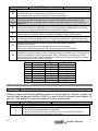
Trouble Table
LED
1
2
3
4
5
Trouble
Low Battery
AC Power Loss
Clock Not Set
Communication Trouble
Bell Loop Trouble
*New in Version 1.2
**New in Version 1.3
4
Installer Manual
TABLE OF CONTENTS
Introduction to the ORBIT-6..................................................................6
Main Features:..................................................................................6
Installation............................................................................................7
Before You Begin..............................................................................7
Technical Data .....................................................................................8
Installer Programming ..........................................................................9
The keypad.......................................................................................9
Restoring Factory Defaults to the ORBIT-6 .......................................9
Introduction to Programming .............................................................9
Programming your Orbit-6............................................................... 10
Viewing the Contents of a Location ................................................. 11
Locations Whose Contents Occupy More Than One Digit ............... 12
Audible Tones and Error Beeps ...................................................... 12
How to program installer parameters............................................... 12
A Programming Tutorial .................................................................. 12
GENERAL SYSTEM PARAMETERS: Locations 00–05 .................... 14
SYSTEM CODES: Locations 06-10 .................................................. 15
SYSTEM TIME: Locations 11-13 ...................................................... 16
Intrusion Zone Types and Zone Sounds: Locations 14-21.................. 16
SPECIAL ZONE TYPES:.................................................................... 18
Utility Outputs: Locations 22-25 ........................................................ 19
Communication Parameters: Locations 20–21.................................... 22
Digital Communicator Controls: Location 26.................................... 22
Central Station Protocols: Location 27-28...................................... 23
Understanding the Code Format ..................................................... 24
Upload/Download Rings: Location 29............................................ 25
System Controls: Location 30 ........................................................... 25
Periodic Test Time: Location 31 ....................................................... 27
Communicator Reporting Codes: Locations 32 through 85................. 27
Installer Manual
5
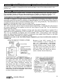
INTRODUCTION TO THE ORBIT-6
The ORBIT-6 is intended to address the needs of many homes, offices, and small
businesses. Its operation is designed around microprocessor and EEPROM
(Electrically Erasable Programmable Read-Only Memory) technology, which stores,
without the need for a source of power, the system’s operating program and its
programmable parameters.
System programming may be performed from any ORBIT-6 keypad, or from a special
LCD Programming Keypad designed specifically for that.
Remote and local system programming is also possible through the use of Rokonet’s
ORBIT Upload/Download software.
Main Features:
Zones (end-of-line resistor required 2200 ohm)
•
6 Programmable Intrusion Zones
•
Special type: Zone 5 – Fire Zone, Zone 6 - tamper zone
•
One Fixed Panic Zone input on the keypad (not on keypad RP206KL6)
•
3 Keypad Emergency Zones (Panic, Fire, Special Emergency)
Alarm Sounder Output
•
Programmable Bell/Siren or Loudspeaker Output
•
Capacity: 750 mA (maximum)
Auxiliary Output for Peripheral Devices
•
Capacity 250 mA (maximum)
Built-In Digital Communicator
•
For Central Station communications (two phone numbers)
•
For Upload/Download functions
•
For follow-me functions
Keypads
•
Up to 4 LED/LCD keypads can be connected
Utility Outputs
•
One transistor-driven (open-collector) triggered output
Security Codes
•
Two Installer Codes
•
One Master (User) Code
•
Nine User Codes (all may be used as duress code)
Periodic Testing
•
Daily test report to central station
Optional Peripherals
•
Four relay outputs expansion
•
Voice Module
Event Log
•
Event log of 100 events
6
Installer Manual
INSTALLATION
Before You Begin
Be sure the actual work is performed by experienced personnel, licensed to carry out
security system installations and capable of implementing all applicable requirements of the
National Fire Protection Association (NFPA-70 and NFPA-74), as well as any federal, state,
and local codes–along with any safety guidelines and regulations which might apply.
Mounting and Wiring the Control Panel (refer to figures 1A, 1B & 1C
on pages
32, 33 & 34)
1. Mount the ORBIT-6’s metal cabinet at a protected dry location, near a source of
unswitched AC Power, a good ground, and access to telephone service. Use the proper
hardware (e.g. anchors, mollys, toggle bolts, etc.), as required, to insure a suitable
mounting.
2. Thread all electrical wiring through a convenient hole in the metal cabinet. To prevent
potential damage, be sure that live AC power is NOT present and that the Standby
Battery is NOT connected. Refer to Figures 1A and 1B. Your wiring may include any
and all of the following:
• connections to Hardwired Zones
• connections to devices requiring Uninterrupted Auxiliary Power (e.g. PIRs, Glass
Break Detectors)
• connections to Smoke Detectors requiring Resettable Power
• connections to any External Sounders
3. If using Utility Output, connect the UO/ECL output, this terminal is designed to activate a
low current device (e.g. a 12 VDC Relay, drawing no more than 70 mA).
If using UO expansion module, connect the UO/ECL terminal to the ECL terminal input
in the expansion module. In this case the first UO on the expansion module will become
UO1. (see figures A1)
4. Make connections from the RJ31X (or equivalent) telephone company interface.
5. Make connections to the system’s keypad(s) by the correspnding wire colors.
6. Make connections to AC Power (via a 16.5 VAC, 25 VA transformer). Do not plug in the
transformer at this time.
7. Have a Standby Battery ready (typically 12 VDC, 4 AH), but do not connect it at this
time.
8. All zone inputs are End Of Line supervised, use 2200 ohm resistors (supplied).
9. When using 8 LED keypad, zones 7 & 8 are end-of-line supervised. Use 2200 ohm
resisters (supplied) when the zones are not in use. For further wiring instructions of the
8 LED keypad, refer to Figure 1C on page 34.
10. If using a Key-switch, use a momentary key-switch. The receiver (if used) must give a
pulse output and not on/off.
11. To connect the panic button use the white wire as (+) and the black wire as (-).
Note: The maximum distance between the panic button and the keypad is 30 meters.
Installer Manual
7
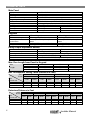
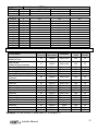
TECHNICAL DATA
Main Panel
Input power
Rechargeable standby battery
Auxiliary Power
Bell/LS Sounder output
Programmable output
Cabinet Dimensions:
Weight
Main Board (dimensions / weight):
Fuse F1
Fuse F2
Fuse F3
16.5 V AC 25 VA via transformer
12 V 4 A-Hours
12 V DC 250 mA maximum
12 V DC 750mA maximum
Open collector Active pull down 70mA maximum
260X218X83 mm (10.2X5.1X3.3 “)
1.84 kg (4 lb)
80X167 mm (3.15X6.6 “)
0.17 kg (0.37lb)
Auxiliary Power
0.5 A
Bell/LS Power
1A
Battery Power
2A
Keypads
6-Zone Keypad
18 mA typical, 30 mA maximum
4-wire up to 300 ft (100 m) from
panel
110X130X25 mm (4.3X5.1X1 “)
0.19 kg (0.42 lb)
Current consumption:
Control panel
connections:
Dimensions:
Weight:
8-Zone Keypad
18 mA typical, 30 mA maximum
4-wire up to 300 ft (100 m) from
panel
110X130X25 mm (4.3X5.1X1 “)
0.19 kg (0.42 lb)
Utility Output Expansion Module
Relay
Transistor
10mA typical, 50mA max
10mA typical, 15mA max
4-wire up to 300 ft (100m) from panel
4 relays, 0.5 A, 24 V DC
4 O.C., 50 mA, 12 V DC
53X85 mm (2.1X3.35 “)
80 gr (0.18 lb)
Current consumption:
Control panel connections:
Contacts:
Dimensions:
Weight:
Max. Run Length from Panel to Keypad
Wire
AWG
Ø (mm)
Meter
Feet
Length
19
0.9
200
660
20
0.8
166
547
22
0.6
100
330
Bell Loudspeaker Wiring Table (Distance in Feet)
AWG
Ø mm
Max.
Current mA
100
300
650
18
1
19
0.9
20
0.8
22
0.6
Feet
Meter
Feet
Meter
Feet
Meter
Feet
Meter
780
260
120
238
79
37
625
208
96
190
64
30
495
165
76
151
50
23
310
103
48
95
32
15
Detectors Distance in Feet
AWG
Ø mm
Max.
Current mA
20
30
40
8
18
1
19
0.9
20
0.8
22
0.6
24
0.5
Feet
Meter
Feet
Meter
Feet
Meter
Feet
Meter
Feet
Meter
3920
2600
1960
1195
793
597
3100
2060
1550
945
628
472
2460
1640
1230
750
500
375
2460
1640
1230
472
314
236
1550
1030
775
296
197
148
Installer Manual
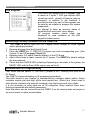
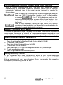
INSTALLER PROGRAMMING
The keypad
The Orbit-6 can support up to 4 keypads, with
a choice of 3 styles, 1 LCD type and two LED
types from which virtually all features may be
accessed. In addition to the functions it
provides for the user, each of the keypads can
be used by an installer to program the system
parameters.
An attempt to enter an incorrect series of
keystrokes will result with 3 error beeps.
All program location values (data) are
displayed by zone indicators on the LED
keypad in binary format.
Restoring Factory Defaults to the ORBIT-6
Your ORBIT-6 and at least one LED Keypad should already be wired together
and/or physically installed
2. Remove all power from the Printed Circuit
3. Place the ORBIT-6’s J1 (DEFAULT) jumper over both corresponding pins. (See
Figures 1A and 1B on page 32 and 33 ).
4. Reapply power (AC and/or Standby Battery) to the PC Board.
5. After a short beep is heard, remove the J1 jumper. The ORBIT-6’s default settings
are now restored.
6. Check that the POWER LED is flashing. Depending on the state of the system, the
READY LED and the Zone LEDs may or may not be lit.
1.
Introduction to Programming
First, check that the panel’s J1 (DEFAULT) jumper is NOT covering both pins on the
PC Board.
The ORBIT-6 stores information in 86 programming locations.
The data stored in any location is represented by numbers and/or letters. Some
locations require just one digit, while most require two. Others (e.g. those used to
store phone numbers and account numbers) may require several more digits.
It is not necessary to enter data into all 86 categories. Many locations have been
factory-programmed with default parameters.
Note that power can be removed from the ORBIT-6, as its memory does not require a
source of power to retain its information.
Installer Manual
9
Programming your Orbit-6
Programming Methods
Local
LED or LCD keypads
Requirements
The keypad must be wired to the Orbit6 panel.
Power must be applied to the Orbit-6.
Orbit Programmer
Easy programming of the control panel
parameters with menu driven LCD
display.
The programmer can store up to 10
Orbit-6 programming sets and copy it
directly to the panel. The programmer
supports both the Orbit-5 and Orbit-6
panels.
Orbit UD*
Local Up/Load Windows version from a
personal computer.
Remote
Orbit UD*
Remote U/D Windows version from a
personal computer.
The programmer will be connected and
receive its power from the panel.
The software must be installed and an
Orbit UD Adaptor cable is connected
between the panel and the computer.
Requirements
The software and applicable modem
with configured access to a telephone
line must be installed.
* Compatible with Windows 95/98/2000 & NT.
10
Installer Manual
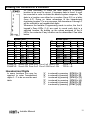
Viewing the Contents of a Location
It’s often necessary to check the data stored in a memory
location to be sure it’s correct. If improper data is found, it must
be corrected in order to obtain the desired system response. The
data in a location can either be a number (from 0-9) or a letter
(from A-F). Doing so takes advantage of the hexadecimal
numbering system. For our purposes, the characters A through F
will be referred to as hexadecimal digits.
Whenever the Installer Programming mode is active, the first 4
keypad’s Zone LEDs (1-4) are used to reveal each digit in a
selected location. By adding up the values assigned to the lit
LEDs, the contents of any location can be determined. See table
below.
ZONE LEDs
ZONE LEDs
I.D.:
4
3
2
1
I.D.:
4
3
2
Value: 8
4
2
1
value: 8
4
2
0
off
off
off
off
8
ON
off
off
1
off
off
off
ON
9
ON
off
off
2
off
off
ON
off
A
ON
off
ON
3
off
off
ON
ON
B
ON
off
ON
4
off
ON
off
off
C
ON
ON
off
5
off
ON
off
ON
D
ON
ON
off
6
off
ON
ON
off
E
ON
ON
ON
7
off
ON
ON
ON
F
ON
ON
ON
EXAMPLE: Zone 4-ON Zone 3-off Zone 2-off Zone 1-ON
TOTAL = 9
EXAMPLE: Zone 4-ON Zone 3-off Zone 2-ON Zone 1-ON
TOTAL = B
Hexadecimal Digits
In some locations you may be
required to enter hexadecimal
digits A - F to do so see the next
table.
Installer Manual
“A” is entered by pressing
“B” is entered by pressing
“C” is entered by pressing
“D” is entered by pressing
“E” is entered by pressing
“F” is entered by pressing
1
1
off
ON
off
ON
off
ON
off
ON
[STAY] + [1]
[STAY] + [2]
[STAY] + [3]
[STAY] + [4]
[STAY] + [5]
[STAY] + [6]
11
Locations Whose Contents Occupy More Than One Digit
When a location contains more than one digit, they cannot be viewed
simultaneously. As soon as a location is accessed, the first digit is displayed
automatically. Additional digits (if they exist) can be displayed by pressing the
following keys:
Used to display the next digit in a location containing at least two
digits; e.g. if 5-6-7-8 is stored in a location, the “5” is displayed first;
by pressing
, the “6” will be displayed; continue this
process to display the entire contents of the chosen location. Error
beeps will be produced when it’s attempted to display digits which
don’t exist
Used to move backwards among the digits stored in a location
containing at least two digits. Error beeps will be produced when it’s
attempted to display digits which don’t exist
Audible Tones and Error Beeps
To confirm an operation, a single, long beep will be heard. However, any improper use
of the keypad resulting in an error or an unacceptable response will produce three
rapid beeps. If heard, repeat the operation or exit the programming mode and try again.
How to program installer parameters
1.
2.
3.
4.
To enter the Installer programming mode:
Press 4 digit Installer code followed by # (factory default 0 2 0 6)
To move to a new location:
Press two digits of location followed by ARM
To enter data into the location:
Press data digits (0 - 9 digits including hexadecimal A-F) followed by #
To exit programming mode:
Press 4 digit installer code followed by ARM
A Programming Tutorial
To get acquainted with some programming basics, a short tutorial has been
prepared. It involves changing the Installer Code from the factory default of 0-2-06 to a sequence of your own choosing. If you can master this operation,
subsequent programming should be easy.
12
Installer Manual
1
2
3
4
5
6
7
Operation
Action
Comments
Enter the
Installer
Programming
mode
Access the
current Installer
Code
(stored in location
“08”)
Enter a unique
Installer Code
(for this tutorial,
we’ll use 3-0-5-7)
Store the data
you have entered
enter the factory default
Installer Code (0-2-0-6);
followed by #
a long beep will sound, confirming
successful entry into Installer
Programming
press [0], [8], [ARM]
no confirming beep will sound
enter [3], [0], [5], [7]
no confirming beep will sound
press [#]
a long beep will sound confirming that
data has been properly stored
if a wrong number of digits entered
three (error) beeps will sound after
pressing #
Check the data
stored in Location
“08”
•the first digit of the stored
data will appear
•observe the Zone LEDs
•press [STAY] [STAY] to
advance to the next digit
•once all four digits have
been displayed, attempts to
view an additional digit will
result in three (error) beeps
•if desired, press [STAY]
and [ARM] to move
backwards
Go to another
location of your
choice
Exit
programming
press
keys
displayed
zone
LEDs
lit
value
none
1 digit
st
2, 1
3
STAY
STAY
2 digit
nd
none
0
STAY
STAY
3 digit
rd
3,1
5
STAY
STAY
4 digit
th
3,2,1
7
press the desired two-digit
location and [ARM]
press [ARM] alone to go to the next
sequential location
enter your Installer Code
and press [ARM]
a long beep will confirm your actions
Installer Manual
13
GENERAL SYSTEM PARAMETERS: LOCATIONS 00–05
Location: 00 Default Enable: Def: 00
PURPOSE: to enable or disable the option of resetting the system to the factory
defaults.
00
55
Enable the option of resetting the system to the factory defaults.
Disable the option of resetting the system to the factory defaults.
Location: 01 MS Lock: Def: 000000
§ MS Lock is a 6-digit security code used in conjunction with Rokonet’s
Upload/Download Software
§ It is designed to provide greater proprietary security to the Central Station
parameters
§ It is NOT necessary to change the MS Lock default value within Installer
Programming; instead, the procedure may be performed from the
Upload/Download Software and then downloaded to the ORBIT-6
for additional information, refer to the Upload/Download Programming
Manual
Location: 02 Phone Number: Primary Central Station (Central Station 1)
To delete an existing phone number, simply press the [#] key; to enter or replace the
phone number required to reach the primary Central Station include all access digits
(e.g. 0 to 9) and the area code. If required, include the following special functions to
achieve the effect listed in the table:
FUNCTION
stop dialing and wait for a new dial tone
wait a fixed period before continuing
switch from Pulse to Tone (or from Tone to Pulse)
SEQUENCE RESULTS
[STAY], [1]
A
[STAY], [2]
B
[STAY], [3]
C
send the DTMF Q character
[STAY], [ * ]
*
send the DTMF # character
[STAY], [#]
#
When done with your complete entry, press [#] to store it. Up to 24 digits can be
entered to the phone number.
For your records, enter the complete phone number below:
Location: 03 Phone Number: Secondary Central Station (Central Station 2)
Same as in Location 02
14
Installer Manual
Location: 04 Callback UD Phone #
Enables greater security for remote Upload/Download operation. This is a number to
which the alarm company computer, equipped with the U/D software, will be
connected.
When a call is made from a computer, using U/D software, to the Orbit-6 panel, the
system will hang-up and call back using this UD phone number. Up to 24 digits can be
entered into the U/D phone number, include all the digits and functions as above in
Location 02. To delete an existing phone number press #.
Location: 05 Account Number
Default: 0000
PURPOSE: to assign the system’s Central Station Account Number
hexadecimal account numbers (those using 0 through 9 and A through F) are
accepted by the ORBIT-6; use the key combinations below to enter hexadecimal digits
“A” through “F”:
hex digit
A
B
C
press
[STAY], 1
[STAY], 2
[STAY], 3
hex digit
D
E
F
press
[STAY], 4
[STAY], 5
[STAY], 6
Acct No.
“0” will not send a digit to the central station, to send “0” use “A” digit
SYSTEM CODES: LOCATIONS 06-10
Location: 06
Access Code
Default: 5678
PURPOSE: to provide data security during Upload/Download operations
this same Access Code must subsequently be entered into the corresponding account
profile in the Upload/Download software (along with the Remote ID codes, see
Location 07, below).
Access Code
Location: 07
Remote ID Code
Default: 0001
PURPOSE: to provide data security during Upload/Download operations this same
Remote ID Code must subsequently be entered into the corresponding account profile
in the Upload/Download software.
Remote ID
Location: 08
Installer Code I
Default: 0206
PURPOSE: the installer code is used by alarm company personnel authorized to
modify the system’s parameters It is recommended to change the “factory default”
Installer Code to one of your own choice.
Installer Code
Installer Manual
15
Location: 09
Installer Code II
Default: 1206
Same as the Installer Code 1, but with a few limitations: It can't modify the "default
code", observe and modify the first installer's codes, modify any MS phone number,
nor observe & modify MS lock code.
Installer Code
Location: 10
Master Code
Default: 1234
PURPOSE: to establish the keypad code for the system’s “chief user”; the
Master Code provides the following special privileges:
• to enter, modify, and delete the remaining nine User Codes Master Code
• to set the system's internal clock
• to perform certain system functions and tests
Note: the Master Code cannot be seen by the installer through the zone LEDs on the
keypad.
SYSTEM TIME: LOCATIONS 11-13
Location: 11
Exit Delay
Default: 030
PURPOSE: to establish the system’s Exit Delay (the interval, in seconds, between
entering a User Code at the keypad and when the system actually arms).
Enter three digits between 001 and 255 seconds
Exit Delay
Location: 12
Entry Delay
Default: 060
PURPOSE: to establish the system’s Entry Delay (in an armed system, the interval, in
seconds, between the moment an entry door is opened and an alarm is triggered).
Enter three digits between 001 and 255 seconds
Entry Delay
Location: 13
Bell Cutoff Time
Default: 04
PURPOSE: to set the interval that the system’s external sounder(s) will operate before
it shuts off automatically.
Sounder
Enter the number of minutes between 01 and 90
Cutoff
INTRUSION ZONE TYPES AND ZONE SOUNDS: LOCATIONS 14-21
Locations 14 through 21 are identical and are corresponding to Zones 1 through 6 or 8
(in the 8-zone keypad), respectively. Each of these locations contains two digits.
• the first digit: Contains the number used to represent the Type of Zone desired
• the second digit: Contains the number used to represent the sound produced
when in alarm
Note: 1. When using 6 zone keypad the system disregards zones 7 - 8.
2. When using 8 zone keypad, zones 7 - 8 must be connected to an EOL
resister when not in use.
16
Installer Manual
Locations: 14-21
st
Zone 1-8: (1st Digit): Type
1 Digit
0
1
2
3
Default:
Zone Type and Comments
Not Used
All unused zones should be given this designation. It is also used to disable a zone
24-Hour
A violation of such a zone will always cause an instant intrusion alarm, regardless of
the system’s armed/disarmed state
Instant (Intrusion)
Causes an immediate intrusion alarm if violated when the system is in arm state. Entry
Delay.
Entry/Exit Delay
If violated, a zone with this designation will not cause an intrusion alarm during the
Entry and Exit Delay periods
Exit (OPEN)/Entry
Such a zone behaves as described above in Entry/Exit Delay, except that if faulted at
4 the time the system is armed, it will be bypassed and NOT prevent system arming.
To avoid an intrusion alarm, however, it must be secured before the expiration of the
Exit Delay period (Location 11).
Entry Follower
zone(s) given this designation will cause an immediate intrusion alarm when violated
5 A
unless an Entry/Exit zone was violated first if so, an Entry Follower zone(s) will remain
bypassed until the end of the Entry Delay period
Interior + Entry Delay Follower
If the system is armed to AWAY (ARM) mode: this type of zone behaves like the Entry
Follower, described above
6 If the system is armed to the STAY mode: this type of zone will be bypassed
Important Note: When arming with "STAY" mode it is possible for the user to eliminate
the entry delay period by pressing the (STAY) key twice in succession when arming
the system.
Fire Zone
Intended for smoke or other types of fire detectors. If violated, will cause an immediate
7 fire alarm. Only Zone 5 can be programmed as a fire zone. A fault in the wiring of any
fire zone, if supervised, will cause a fire alarm, manifested by a rapid flushing of the
keypads' Fire LED.
Tamper Zone
8 Only Zone 6 can be a Tamper Zone. It operates the same as 24 hours Zone, but this
type has a special reporting code.
Zone
9 Panic
If violated an immediate panic alarm will be announced.
Key-switch Zone - Instant
desired for system arming and disarming an external SPST spring - loaded,
A Ifnormally
open, momentary type key switch can be added. The key switch permits an
instant arm and disarming of the system after tripping.
Key-switch Zone - Delayed
B Such a zone behaves as described above in "key switch zone instant", except when
arming the system an exit delay will follow.
Latch-Key-switch Zone – Instant: If desired for system arming/disarming, connect
**C an external SPST latching type (non-momentary) key-switch to any zone terminals,
given this designation.
Latch-Key-switch Zone – Delayed: Such a zone behaves as described above in
**D "latched key switch zone instant", except when arming the system an exit delay will
follow.
** New in Version 1.3
Installer Manual
17
Locations: 14-21
nd
Zone 1-8: (2nd Digit): Sound
Default:
2
Digit Zone Sound and Comments
Silent
a violation during the armed period will produce no sound
0
the resulting alarm can still be reported to the Central Station
External Sounder (Continuous)
causes the external sounding device to annunciate steadily, without breaks in the
1
(default) sound cadence the sound will continue until the sounder “times out” or the system is
disarmed
External Sounder (Pulses)
causes the external sounding device to produce a pulsed (or staggered) annunciation
2
this sound is usually recommended for fire alarm annunciation
Keypad Sounder Only
3
causes the piezo sounder within the system’s keypad(s) (only) to beep rapidly
External Sounder + Keypad Sounder
causes the external sounding device to annunciate continuously, without breaks in the
4
sound cadence causes the piezo sounder within the system’s keypad(s) to beep rapidly
External Sounder When Armed / Keypad Sounder When Disarmed
related to 24H zones
5
when alarm during disarm, the keypad’s buzzer will be activated
when alarm during armed system, the external sounder will be activated
Door Chime
assigned to an opening which, when violated during the disarmed period, will cause the
system’s keypad(s) to beep once during an alarm, the external sounding device will
6
annunciate continuously, without interruption. When alarm occurs during armed system
only the external sounder will be activated.
Zone
Location
Z1
Z2
Z3
Z4
Z5
Z6
Z7
Z8
14
15
16
17
18
19
20
21
Type
Sound
(3)
(5)
(2)
(6)
(2)
(2)
(0)
(0)
(1)
(1)
(1)
(1)
(1)
(1)
(0)
(0)
* (x) define the type and sound default
SPECIAL ZONE TYPES:
Location: 18 Zone 5: Fire Zone
Zone 5 is reserved as a Fire Zone, supports four-wire Smoke Detectors. Smoke
Detector power must be interruptible in order to reset a detector “latched” in alarm. As
such it should be derived from the UO/ECL or one of the UOs terminal (see Figures 1A
and 1B). The related UO should be defined as AUX power switch.
Location: 18 Zone 5: (1st Digit): Type
st
1 Digit
7
18
Default: Fire
Zone Type and Comments
Fire
A fire zone cannot be disabled or bypassed.
A fault in the wiring to the zone will cause a Fire Trouble (fire LED blinks).
A short in the zone wiring will cause a fire alarm.
Installer Manual
Location: 18 Zone 5: (2nd Digit): Sound
Default: External Sounder (Pulses)
For fire zone the recommended (default) zone sound is “External sounder pulsed”
However it is possible to change the zone sound and type to any of the ones provided in the
previous list.
Location: 19 Zone 6: Tamper Zone
Zone 6 is reserved as a Tamper Zone. This zone can be programmed to any zone type (except
Fire) including Tamper. If the zone was programmed as Tamper, in violation, a Tamper Code
report will be sent and the Tamper LED on the keypad (marked as 6/Tmp) will light up.
UTILITY OUTPUTS: LOCATIONS 22-25
The ORBIT-6 supports one open collector Utility Output (derived between the UO/ECL and AUX
terminals) which can be used for switching an external device on or off. Once the Utility Output is
activated the device will be connected between AUX (+12V) and ground (0V). This connection is
capable of switching light loads of no more than 70mA.
Note: When activated the utility output is switched to the Negative Polarity.
The “UO” can be also used to reset a “latched” Smoke Detector(s). In that case the 12V power to
the smoke detector will be supplied via the UO (see Figures 1A and 1B). The UO should be
defined as AUX switch.
If the Utility Output Expansion Module is being used, the same information in Location 22 is
applicable for the programming of UO2 (Location 23), UO3 (Location 24), and/or UO4 (Location
25). It is not necessary to program all of the available “UOs”, unless they’re used. Note that
when the Utility Output Expansion Module is employed, the original Utility Output on the Main
Board (the UO/ECL terminal) is no longer available.
Important: In order to use the Utility Output Expansion you have to define the module in
Location 30.
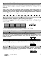
Because of the “UO’s” modest 70 mA
current capability, it will be necessary to
use
an
“intermediate”
relay-whose
physical contacts can switch far greater
currents (limited by their contact rating).
The figure at the left shows how such a
relay can trigger a strobe light. If used in
this manner, the “UO” cannot be used to
reset a “latched” Smoke Detector(s).
22
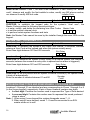
If more than one “UO” output is necessary, a
Utility Output Expansion Module is available. Its
four “UOs” (U01, UO2, UO3, and UO4) replace
the ORBIT-6’s single “on-board ”UO”. The “UOs”
on the Utility Output Expansion Module are
relay-based, and allow a maximum current of
500 mAs. Refer to Figures 1A and 1B (pages 32
and 33), for wiring instructions and additional
information. The figure at the right, shows how a
Utility Output on the “UO Expander” can be used
to switch a table lamp on and off.
Installer Manual
23)
16.
19
Digit Event and Result
00
Not Active
(default) UO offers no response to any system activity
01
02
03
04
05
06
07
08
09
0A
0B
0C
0D
0E
0F
10
11
12
13
14
15
16
20
Arm Follow (Latch)
U0 is activated when the system is armed. The activation occurs after the expiration of
the exit/delay period. The U0 remains active (latched) while the system is armed. When
disarming the system the U0 deactivates (unlatches).
Arm Follow (Pulse)
UO is activated when the system is armed. The activation occurs after the expiration of
the exit/delay period. The UO is activated for several seconds (pulse), after which is
deactivated.
Alarm Follow (Latched)
UO is immediately activated when the system goes into any type of alarm (i.e. intrusion,
fire, keypad-initiated panic) UO remains active (latched) for the duration of the
alarm-even after the system’s sounder “times out” UO is deactivated when the system is
disarmed
Alarm Follow (Pulse)
UO is immediately activated for several seconds and then deactivated whenever the
system goes into any type of alarm (i.e. intrusion, fire, keypad-initiated panic)
Zone 1 Alarm Follow (Latched)
U0 is immediately activated when an alarm occurs on Zone 1. U0 remains active
(latched) for the duration of the alarm - even after the system sounder "times out". U0 is
deactivated when Zone 1 goes into normal condition.
Zone 1 Alarm Follow (Pulsed)
U0 is immediately activated for several seconds (pulsed) and then deactivates whenever
Zone 1 goes into alarm.
Zone 2 Alarm Follow (Latched)
Zone 2 Alarm Follow (Pulsed)
Zone 3 Alarm Follow (Latched)
Zone 3 Alarm Follow (Pulsed)
Zone 4 Alarm Follow (Latched)
Zone 4 Alarm Follow (Pulsed)
Zone 5 Alarm Follow (Latched)
Zone 5 Alarm Follow (Pulsed)
Zone 6 Alarm Follow (Latched)
Zone 6 Alarm Follow (Pulsed)
Zone 7 Alarm Follow (Latched)
Zone 7 Alarm Follow (Pulsed)
Zone 8 Alarm Follow (Latched)
Zone 8 Alarm Follow (Pulsed)
Panic Follow (Latched)
UO is activated immediately when a PANIC alarm is triggered by a violation of a zone,
defined as Panic, or by pressing the keypad’s [1] and [2] keys simultaneously for two
seconds. U0 is deactivated when the system is disarmed.
Panic Follow (Pulse)
UO is activated for several seconds when a PANIC alarm is triggered by a violation of a
zone, defined as Panic, or by pressing the keypad’s [1] and [2] keys simultaneously for
two seconds.
Installer Manual
17
18
19
1A
1B
1C
1D
1E
1F
20
21
22
23
Special Emergency Keying Follow (Latched)
UO is activated immediately when pressing the keypad’s [7] and [8] keys simultaneously
for two seconds. U0 is deactivated when the system is disarmed.
Special Emergency Keying Follow (Pulsed)
UO is activated for several seconds when pressing the keypad’s [7] and [8] keys
simultaneously for two seconds.
Fire Keying Follow (Latched)
UO is activated immediately when a Fire alarm is triggered by a violation of zone 5,
defined as Fire, or by pressing the keypad’s [4] and [5] keys simultaneously for two
seconds. U0 is deactivated when the system is disarmed.
Fire Keying Follow (Pulse)
UO is activated when a Fire alarm is triggered by a violation of zone 5, defined as Fire,
or by pressing the keypad’s [4] and [5] keys simultaneously for two seconds.
User Activated (Toggle)
UO may be activated by the user through the entry of [*]+[2]+[User Code]+[X], where X
refers to the utility output number.
The first entry of the above sequence activates the UO and causes it to latch in the
opposite of its current state. The system briefly lights the Zone LED corresponding to the
selected UO and produces a single confirming beep subsequent entries toggle the
response from ON to OFF to ON, etc.
User Activated (Pulse)
UO may be activated by the user through the entry of [*]+[2]+[User Code]+[X], where X
refers to the utility output number.
The entry activates the UO for several seconds (pulse). The system briefly lights the
Zone LED corresponding to the selected UO and produces a single confirming beep
subsequent entries repeat this pattern.
AUX POWER Switch (Fire)
Until triggered, UO is normally activated and is designed to be a part of the circuit
supplying power to the Smoke Detector(s); see Figure 1A and 1B.
After a Fire Alarm is disarmed, it may be necessary to reset any Smoke Detector(s)
which may be “latched” in alarm. A “latched” Smoke Detector will cause the keyboard’s
FIRE LED to remain lit, even though the panel may be disarmed. To reset a Smoke
Detector, a “UO” used in this manner must be momentarily deactivated; this action is
performed by the user, who must enter [*]+[2]+[User Code]+[X], where [X] refers to the
UO number (i.e. 1,2,3, or 4) in the circuit providing Smoke Detector power. If this is not
done, it will be impossible to arm the panel; please advise your customer of this
contingency which is stated in the ORBIT-6’s User Manual.
Duress Code Follow (Pulse)
U0 is activated for several seconds (and then deactivates) when any duress code is
entered.
AC Loss Follow (Latched)
U0 is activated due to a lack of power from the commercial AC. U0 is deactivated when
the system is operating properly from commercial (AC) power.
AC Loss Follow (Pulse)
U0 is activated for several seconds (and then deactivates) due to a lack of power from
the commercial AC.
Low Battery Follow (Latched)
U0 is activated due to low power from the backup battery. U01 is deactivated when the
battery is in good condition.
Low Battery Follow (Pulse)
U0 is activated for several seconds due to low power from the backup battery.
Voice Module Enable
The U0 is activated after FM phone number dialing has been made due to alarm. The U0
deactivates after the FM period termination.
Installer Manual
21
Duress Code Follow (Latched)
UO is activated when any duress code is entered. The UO deactivates either when
arming the system or disarming the system due to an alarm that was activated from the
emergecy keypad keys, 24-hour zone violation or tamper zone violation.
Follow Chime (Pulse) (Ver. 1.2) UO is activated for several seconds whenever a
keypad sounds its chime.
Follow Bell Latched NO (Ver. 1.2) UO is activated whenever the bell is activated. UO
is deactivated at the bell cut-off time.
Follow Bell Latched NC (Ver.1.3)
24
25
26
27
28
Follow Ready NO (Ver.1.3) UO is activated whenever the system is in the ready state.
Locations:
22
UO1
Action
23
UO2
Action
24
UO3
Action
25
UO4
Action
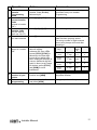
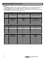
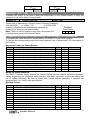
COMMUNICATION PARAMETERS: LOCATIONS 26–29
Locations 26 and 27 allow you to define the manner in which the ORBIT-6 communicates with the
Central Station when it reports alarms, restorals, troubles, openings/closings, and tests.
Digital Communicator Controls: Location 26
• First digit: determines the number (or hexadecimal digit) corresponding to the
Dialing Method / Duty Cycle / Redial Time desired
• Second digit: determines the number corresponding to the
Attempts / Answering Machine Use / UL Installation
Attempts
Attempts sets the
number of times the
ORBIT-6 will redial
the Central Station
after failing to
establish a
successful
communication.
Location: 26
st
1 Digit
8
1
9
4 (default)
5
D
3
B
7
F
Answering
in Use
Machine
If enabled to defeat an
answering machine, two
phone calls must be
made to the premises. On
the first call let the phone
ring once (by pushing the
space bar on the U/D
software keyboard). The
panel detects this ring
and starts a 60sec timer
during which the panel
will answer the next call
on the first ring.
UL Installation
Voice Module
If the ORBIT-6 is installed
in accordance with UL
requirements, for a
Residential Installation
(UL 1641), the operation of
the unit’s Digital
Communicator must be
modified so as to disable
features, which are
inappropriate.
If enabled (“YES”) voice
messages will be sent. If
“NO” then tones will be
used to represent an active
alarm.
Dialer Controls: (1st Digit):
Dialing Method
DTMF
Pulse @ 20 pps
Pulse @ 20 pps
DTMF
Pulse @ 20 pps
Pulse @ 20 pps
Pulse @ 10 pps
Pulse @ 10 pps
Pulse @ 10 pps
Pulse @ 10 pps
Duty Cycle
N/A
67/33
67/33
N/A
61/39
61/39
67/33
67/33
61/39
61/39
* Redial Central Station
after 60 seconds
after 30 seconds
after 60 seconds
after 30 seconds
after 60 seconds
after 60 seconds
after 30 seconds
after 60 seconds
after 30 seconds
after 60 seconds
* redial refers to the number of seconds the ORBIT-6 will wait before redialing a busy or unresponsive Central Station
phone number.
22
Installer Manual
Location: 26
nd
2
Digit
0
1
2
3
(default)
4
5
6
7
8
9
A
B
C
D
E
F
Dialer Controls: (2nd Digit):
Attempts
3
8
3
Answering Machine
No
No
Yes
UL Installation
No
No
No
Voice Module
No
No
No
8
3
8
3
8
3
8
3
8
3
8
3
8
Yes
No
No
No
No
Yes
Yes
No
No
Yes
Yes
No
No
Yes
Yes
Yes
Yes
Yes
Yes
No
No
No
No
Yes
Yes
Yes
Yes
No
No
No
No
Yes
Yes
Yes
Yes
Yes
Yes
Yes
Yes
Central Station Protocols: Location 27-28
(PPS)
Kissoff/
pulses/sec Handshake
Format Name
Silent Knight/
ADEMCO Slow
Silent Knight/
ADEMCO Slow Extended
Radionics/DCI/ Franklin slow
Silent Knight Fast
Silent Knight Fast Extended
Sescoa/Franklin/Vertix/ DCI fast
Sescoa/Franklin/Vertix/DCI
Extended
Universal high speed
Radionics
Radionics
Radionics Extended
Radionics Extended
Radionics
Radionics
Radionics Extended
Radionics Extended
Radionics
Radionics
Radionics Extended
Radionics Extended
Validation
InterDigit
Time
Code
format
10
1400Hz
Dual round
650
0F
10
1400Hz
Dual round
650
4F
10
20
20
20
2300 Hz
1400 Hz
1400 Hz
2300Hz
Dual round
Dual round
Dual round
Dual round
650
650
650
650
17
0E
4E
16
20
2300Hz
Dual round
650
56
20
20
20
20
20
40
40
40
40
40
40
40
40
2300Hz
1400 Hz
2300Hz
1400 Hz
2300Hz
1400 Hz
2300Hz
1400 Hz
2300Hz
1400 Hz
2300Hz
1400 Hz
2300Hz
Dual round
Dual round
Dual round
Dual round
Dual round
Dual round
Dual round
Dual round
Dual round
Parity
Parity
Parity
Parity
390
390
390
390
390
390
390
390
390
390
390
390
390
12
02
12
42
52
00
10
40
50
20
30
60
70
Example: to use ADEMCO slow enter 0F to location 27
Installer Manual
23
Understanding the Code Format
To understand and modify the Code format according to a specific central station see the
following
• First digit: determine the number corresponding to the desired combination of:
Kissoff/Handshake Freq / Message Validation / Extended–Non-Extended Format)
• Second digit: determine the number (or letter) corresponding to the desired combination
of: Dialing Rate / Interdigit Time / Data Frequency
st
Location: 27
CS Protocols: (1 Digit):
st
1 Digit
0
(default)
1
2
3
4
5
6
7
Location: 27
nd
2
Digit
0
(default)
1
2
3
4
5
6
7
8
9
A
B
C
D
E
F
24
Format
Kissoff/Handshake Freq
Message Validation
Non-Extended
1400 Hz
Dual Round Compare
Non-Extended
Non-Extended
Non-Extended
Extended
Extended
Extended
Extended
2300 Hz
1400 Hz
2300 Hz
1400 Hz
2300 Hz
1400 Hz
2300 Hz
Dual Round Compare
Parity
Parity
Dual Round Compare
Dual Round Compare
Parity
Parity
CS Protocols: (2
nd
Digit):
Data Rate
Interdigit Time
Data Frequency
40 pulses/sec
390 ms
1800 Hz
33
20
10
40
33
20
10
40
33
20
10
40
33
20
10
390
390
390
650
650
650
650
390
390
390
390
650
650
650
650
1800 Hz
1800 Hz
1800 Hz
1800 Hz
1800 Hz
1800 Hz
1800 Hz
1900 Hz
1900 Hz
1900 Hz
1900 Hz
1900 Hz
1900 Hz
1900 Hz
1900 Hz
pulses/sec
pulses/sec
pulses/sec
pulses/sec
pulses/sec
pulses/sec
pulses/sec
pulses/sec
pulses/sec
pulses/sec
pulses/sec
pulses/sec
pulses/sec
pulses/sec
pulses/sec
ms
ms
ms
ms
ms
ms
ms
ms
ms
ms
ms
ms
ms
ms
ms
Installer Manual
Location: 28
CS Protocols:
When selecting a contact ID & SIA format, all the reporting codes will be automatically
applied to the locations of the reporting codes.
To change a code, enter a new code (according to the type of event – see page 30) to the
corresponding location.
When selecting the Pulsed Protocol the default for all the reported codes will be “00” and
any other code should be entered manually
To remove a particular reporting code from any of the 3 Protocols enter “00” into the
corresponding location.
Important: Choose the code format only after defining the zone parameters. Changing a
zone type after selecting the code format WILL NOT change the zone’s reporting code and
a faulty report will be sent to the central station.
Digit
Format Name
00
Pulsed Protocol
01
Contact ID
02
SIA
**03
Ademco 4/2 Express
(Ver. 1.3)
Interdigit Time
Data Frequency
NA
390 ms
NA
1800 Hz
Upload/Download Rings: Location 29
Location 29 sets the number of rings that the ORBIT-6 will wait before automatically
answering an incoming call. If such a call was initiated by the alarm company’s
Upload/Download software, a process begins which allows a Remote Programming
session to take place.
Location: 29
Number of Rings
Default: 12
Choose a number of rings greater than that which the customer will normally wait to answer
Number
an incoming call enter two digits; (between 00-15 rings)
of Rings
Note: if an Answering Machine is in use and so programmed
(see Location 26 / 2nd Digit), entries made in this location will be ignored
SYSTEM CONTROLS: LOCATION 30
Location 30 allows you to specify some additional parameters, which determine how the
ORBIT-6 will operate. The location contains two digits.
• First digit: determine the number (or letter) corresponding to the choices involving
Quick Arm / Quick Bypass / UO Extender / Loudspeaker / Bell-Siren
• Second digit: determine the number (or letter) corresponding to the use of
Silent Panic / Bell Squawk on Arming / 3 Minute Bypass
st
Comments on System Controls (Location 30: 1 Digit)
Quick Arm
Quick Bypass
UO Extender
Loudspeaker/Bell-Siren
Quick Arm
eliminates the
need for entering
a User Code when
arming to the STAY
or AWAY modes.
simply pressing
[STAY] or [ARM] will
arm the system to
the respective mode
Eliminates the
need to enter a
User Code when
bypassing a zone.
select UO Extender
if the Utility Output
Expansion Module is
installed
select Loudspeaker if the
external sounder(s) is NOT
equipped with a built-in sound
driver; doing so causes the
ORBIT-6 to produce an
oscillating frequency for the
device, select Bell/Siren if the
external sounder(s) is a bell or
a buzzer or equipped with a
built-in electronic sound driver;.
Installer Manual
25
Comments on System Controls (Location 30: 2nd Digit)
Silent Panic
Bell Squawk on Arming
3 Minute Bypass Enabled
If “NO”, the panic alarm
will be AUDIBLE at the
External Sounder and
visual on the keypad.
If “YES”, the panic alarm
will be INAUDIBLE at
the External Sounder
and invisable on the
keypad.
If selected, Bell Squawk on
Arming will produce a brief
confirmation “chirp” from the
system’s external sounder(s)
once the system is armed
and the Exit Delay expires
If selected, 3-Minute Bypass Enabled
bypasses all zones automatically for 3
minutes when power is restored to an
“unpowered” system–to prevent
potential false alarms by allowing time
for the stabilization of motion and/or
smoke detectors
Location: 30
st
1 Digit
0
1
2
3
4
5
6
7
8
9
(default)
A
B
C
D
E
F
st
System Controls: (1 Digit):
Loudspeaker/Bell-Siren
Bell-Siren
Bell-Siren
Bell-Siren
Bell-Siren
Bell-Siren
Bell-Siren
Bell-Siren
Bell-Siren
Loudspeaker
UO Extender
No
No
No
No
Yes
Yes
Yes
Yes
No
Loudspeaker
Loudspeaker
Loudspeaker
Loudspeaker
Loudspeaker
Loudspeaker
Loudspeaker
Location: 30
System Controls: (2
nd
Quick Bypass
No
No
Yes
Yes
No
No
Yes
Yes
No
Quick Arm
No
Yes
No
Yes
No
Yes
No
Yes
No
No
No
Yes
No
No
Yes
Yes
Yes
Yes
Yes
Yes
No
No
Yes
Yes
No
Yes
No
Yes
No
Yes
Digit):
Digit
3 Minute Bypass
0
1
2
3
**4
**5
**6
**7
8
9
A
B
(default)
**C
**D
**E
**F
** New in Ver. 1.3
Disabled
Disabled
Disabled
Disabled
Disabled
Disabled
Disabled
Disabled
Enabled
Enabled
Enabled
No
No
No
No
Yes
Yes
Yes
Yes
No
No
No
Bell Squawk on
Arm
No
No
Yes
Yes
No
No
Yes
Yes
No
No
Yes
Enabled
No
Yes
Yes
Enabled
Enabled
Enabled
Enabled
Yes
Yes
Yes
Yes
No
No
Yes
Yes
No
Yes
No
Yes
nd
2
26
CZ Installation
Silent Panic
No
Yes
No
Yes
No
Yes
No
Yes
No
Yes
No
Installer Manual
System Controls:
ST
1 Digit
System Controls:
nd
2 Digit
PERIODIC TEST TIME: LOCATION 31
If desired, the ORBIT-6 can send a daily test transmission to the Central Station to verify the
operation of the unit’s Digital Communicator.
Location: 31
Periodic Test Time
Default: 0000
Sets a fixed, daily time for sending an ORBIT-6 test transmission to the Central Station. The
chosen time is expressed in 24-Hour format (following examples):
8:30 AM=0830
11:15AM=1115
4:30 PM=1630
Periodic
If desired, disable the test transmission capability by
Test
Time
accepting (or entering) the default (0000)
Note: Failure to set the systems’ time clock, will prevent the
code from being sent to the Central Station.
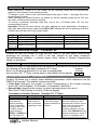
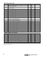
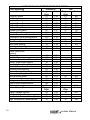
COMMUNICATOR REPORTING CODES: LOCATIONS 32 THROUGH 86
To program the codes that will be transmitted by the ORBIT-6 to the Central Station.
To prevent the corresponding event from being reported, use a “double-zero” (00, the default) in
the location.
Reporting Codes for Alarm Events:
Location
Description
Digits
Default
32
33
34
35
36
37
38
39
40
41
42
Zone 1 Alarm Reporting code
Zone 2 Alarm Reporting code
Zone 3 Alarm Reporting code
Zone 4 Alarm Reporting code
Zone 5 Alarm Reporting code
Zone 6 Alarm Reporting code
Zone 7 Alarm Reporting code
Zone 8 Alarm Reporting code
Keypad Fire Alarms Reporting code
Keypad Panic Reporting code
Keypad Special Emergency Reporting code
2
2
2
2
2
2
2
2
2
2
2
00
00
00
00
00
00
00
00
00
00
00
Report Code
Notes on Alarm Restorals
An ORBIT-6 Restoral Report informs the Central Station that the external sounder’s operation,
initially triggered by the respective alarm condition, has either “timed out” or been silenced by the
act of system disarming. Be sure to check with Central Station personnel if restorals are
permitted and, if so, what codes are required.
Restoral Codes
Location
Description
Digits
Default
43
44
45
46
47
48
49
50
51
52
53
Zone 1 Restoral Code
Zone 2 Restoral Code
Zone 3 Restoral Code
Zone 4 Restoral Code
Zone 5 Restoral Code
Zone 6 Restoral Code
Zone 7 Restoral Code
Zone 8 Restoral Code
Keypad Fire Restoral Code
Keypad panic Restoral Code
Keypad Special Emergency Restoral Code
2
2
2
2
2
2
2
2
2
2
2
00
00
00
00
00
00
00
00
00
00
00
Installer Manual
Report Code
27
Other Reporting Codes
Location
54
55
56
57
58
59
60
61
62
63
64
65
66
67
68
69
70
71
72
73
74
75
76
77
Description
Daily test Report Code sent everyday at the time
specified in Location 24
User 0 arm (the “Master” Code, “Quick Arm” OR
“Keyswitch” Arm)
User 1 arm Reporting code
User 2 arm Reporting code
User 3 arm Reporting code
User 4 arm Reporting code
User 5 arm Reporting code
User 6 arm Reporting code
User 7 arm Reporting code
User 8 arm Reporting code
User 9 arm Reporting code
Forced arm (when the system is armed with a
bypassed zone) Reporting code
Stay arm when the system is armed to the Stay
(At Home) mode) Reporting code
User 0, disarm Reporting code (key switch disarm)
User 1 disarm Reporting code
User 2 disarm Reporting code
User 3 disarm Reporting code
User 4 disarm Reporting code
User 5 disarm Reporting code
User 6 disarm Reporting code
User 7 disarm Reporting code
User 8 disarm Reporting code
User 9 disarm Reporting code
Duress Disarm
Digits
Default
2
00
2
00
2
2
2
2
00
00
00
00
2
00
2
00
2
2
2
2
2
00
00
00
00
00
Report Code
Trouble Reports and Restorals
Location
78
79
80
81
82
83
84
85
**86
Description
Digits
Low Battery Reporting code
2
loss of AC Power (for at least 15 min) Reporting code
2
Fire zone trouble Reporting code
2
Bell Loop Interrupted Reporting Code
2
Low Battery restore Reporting code
2
Loss of AC Power restore Reporting code
2
Fire zone trouble Restore Reporting code
2
Bell Loop Restored Reporting Code
2
Auto Arm
2
Default
00
00
00
00
00
00
00
00
00
Report Code
**New in Version 1.3
28
Installer Manual
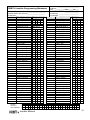
ORBIT-6 Installer Programming Worksheet
Customer Phone No: (
) ___________________
Central Station Account No:___________________
Comments:________________________________
Location
Description
00
01
02
03
04
05
06
07
08
09
10
11
12
13
14
15
16
17
18
19
20
21
22
23
24
25
26
27
28
29
30
31
32
33
34
35
36
37
38
39
40
41
42
43
Default Disable
MS LOCK
Phone No. CS 1
Phone No. CS 2
UD Call back
CS Account No.
Access Code
Remote ID Code
Installer Code 1
Installer Code 2
Master Code
Exit Delay
Entry Delay
Bell Cutoff Time
Zone 1 Settings
Zone 2 Settings
Zone 3 Settings
Zone 4 Settings
Zone 5 Settings
Zone 6 Settings
Zone 7 Settings
Zone 8 Settings
Utility Output 1
Utility Output 2
Utility Output 3
Utility Output 4
Dialer Controls
CS Protocols 1
CS Protocols 2
U/D Rings
System Controls
Periodic Time Set
Zone 1 Alarm
Zone 2 Alarm
Zone 3 Alarm
Zone 4 Alarm
Zone 5 Alarm
Zone 6 Alarm
Zone 7 Alarm
Zone 8 Alarm
Kpd Fire Alarm
Kpd Panic Alarm
Kpd SP Alarm
Rst Code Zone 1
Phone 1
Phone 2
UD Call back
Entry
See below
See below
See below
Customer ________________________
Address _________________________
City ____________ State _____Zip ___
Date of Installation: ________________
Installer(s): ______________________
Comments: ______________________
Location Description
44
45
46
47
48
49
50
51
52
53
54
55
56
57
58
59
60
61
62
63
64
65
66
67
68
69
70
71
72
73
74
75
76
77
78
79
80
81
82
83
84
85
**86
Entry
Rst Code Zone 2
Rst Code Zone 3
Rst Code Zone 4
Rst Code Zone 5
Rst Code Zone 6
Rst Code Zone 7
Rst Code Zone 8
Rst Kpd Fire
Rst Kpd Panic
Rst Kpd SP
Rpt Code per Test
User 0 Arm
User 1 Arm
User 2 Arm
User 3 Arm
User 4 Arm
User 5 Arm
User 6 Arm
User 7 Arm
User 8 Arm
User 9 Arm
Forced Arm
Stay Arm
User 0 disarm
User 1 disarm
User 2 disarm
User 3 disarm
User 4 disarm
User 5 disarm
User 6 disarm
User 7 disarm
User 8 disarm
User 9 disarm
Duress Disarm
Rpt Code Low Bat
Rpt Code AC Loss
Rpt Code Fire Tbl.
Rpt Code Bell Loop
Rst Code Low Bat
Rst Code AC Loss
Rst Code Fire Tbl.
Rst Code Bell Loop
Auto Arm
**New in Ver. 1.3
02
03
04
Installer Manual
29
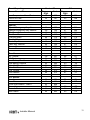
CONTACT ID & SIA REPORT CODES FOR ORBIT 6
Event Reporting
Contact ID
SIA
Zones Alarms/Disarm
Program
Code
Program
Code
Digit
Digit
Exit/Entry Alarm
01
134
01
BA
Exit/Entry Restore
01
134
02
BH
Burglary Zone Alarm
03
130
03
BA
Burglary Zone Restore
03
130
04
BH
24 Hour Zone Alarm
05
133
05
BA
24 Hour Zone Restore
05
133
06
BH
Tamper Zone Alarm
07
137
07
TA
Tamper Zone Restore
07
137
08
TR
Smoke Zone Alarm/Restore
09
111
Combustion Zone Alarm/Restore
1A
112
Water Flow Zone Alarm/Restore
11
113
11
WA
Heat Zone Alarm
12
114
12
KA
Heat Zone Restore
12
114
13
KH
Duct Zone Alarm/Restore
14
116
Flame Zone Alarm/Restore
15
117
Panic Zone Alarm
Restore
Silent Alarm
16
122
Audible Alarm
17
123
Perimeter Zone Alarm/Restore
18
131
18
NL
Interior Zone Alarm/Restore
19
132
Day/Night Zone Alarm/Restore
2A
135
Outdoor Zone Alarm/Restore
21
136
General Alarm/Restore
22
140
Sensor Tamper Alarm/Restore
23
144
24 Hour Non Burg Alarm/Restore
24
150
Gas Detected Alarm
25
151
25
GA
Gas Detected Restore
25
151
26
GH
Refrigeration Zone Alarm/Restore
27
152
Loss of Heat Alarm/Restore
28
153
Water Leakage Alarm
29
154
29
WA
Zones Alarms/Disarm
Program
Code
Program
Code
Digit
Digit
Water Leakage Restore
29
154
3A
WH
Foil Break Alarm/Restore
31
155
Low Battled Gas level Alarm/Restore
32
157
High Temperature Alarm/Restore
33
158
33
DA
30
Installer Manual
Event Reporting
Zones Alarms/Disarm
Low Temperature Alarm/Restore
Los of Air Flow
Contact ID
Program
Code
Digit
34
159
35
161
SIA
Program
Code
Digit
34
DA
35
DB
Special
Special Emergency Key Alarm
Special Emergency Key Restore
Fire Zone Alarm
Fire Zone Restore
Fire Key Alarm
Fire Key Restore
Panic Key Alarm
Panic Key Restore
Duress Alarm
Duress Restore
4A
4A
42
42
44
44
46
46
48
48
100
100
110
110
115
115
120
120
121
121
4A
41
42
43
44
45
46
47
48
49
MA
MH
FA
FH
FA
FH
PA
PH
HA
HH
Troubles
AC Trouble
AC Restore
Low Battery Trouble
Low Battery Restore
Main Bell Trouble
Main Bell Restore
Fire Trouble
Fire Restore
5A
5A
52
52
54
54
56
56
301
301
302
302
321
321
373
373
5A
51
52
53
54
55
56
57
AT
AR
YT
YR
YA
YH
FT
FJ
O/C Access
User Arm
User Disarm
Quick Arm/Disarm - User 0
Forced Arm
Periodic Test
Auto Alarm
6A
6A
62
63
64
65
401
401
408
574
602
403
6A
61
CL
OP
63
64
65
CF
RP
CA
Installer Manual
31
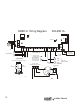
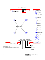
ORBIT-6 Wiring Diagram
FIGURE 1A
TR1
SIG
IN
J3
P1
UR1
SET
PHONE
TIP
RING
J1
DEFAULT
J2
LINE
TELEPHONE
SET
TO TELEPHONE
LINE
AUX COM CLK
RED BLK YEL
DAT
Z1
GRN
COM
Z2
Z3 COM Z4
Z5
Z6
C O M TMP
AUX
UO
ECL
BELL/LS
+
-
AC
TO ZONES CONTACTS
+
TO KEYPAD(S)
16.5 Vac
30 VA
12VDC 250 mA
POWER SUPPLY
TYPICAL BURGLARY
ZONE WIRINGS
(TWO DETECTIONS FOR EACH ZONE)
PROGRAMMABLE
OPEN COLLECTOR
MAX 70mA OR
TO UO EXPANDER
BELL
OR
12VDC
SUPERVISING
RELAY
N/O
CONTACTS
Z5 COM
UO
AUX
12VDC
750 mA MAX
LOUD
SPEAKER
TYPICAL FIRE
ZONE WIRINGS
(4 WIRE SMOKE DETECTIONS )
N/C
CONTACTS
+IN
-IN
+OUT
ALARM +OUT
CONTACT
END OF LINE RESISTORS
2,2 K 1/4 WATT
32
RECHARGEABLE
BATTERY
12V 4ah typical
Installer Manual
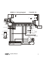
ORBIT-6 Wiring Diagram
FIGURE 1B
TR1
SIG
IN
J3
P1
UR1
SE T
PH O NE
TIP
RING
DEFAULT
J1
J2
LIN E
TELEPHONE
SET
TO TELEPHONE
LINE
AUX COM CLK DAT Z1 C O M
RED BLK YEL GRN
Z2
Z3 COM Z4
Z6 AUX UO
Z5 C O M TMP
ECL
BELL/LS
+
-
AC
TO ZONES CONTACTS
+
TO KEYPAD(S)
RECHARGEABLE
BATTERY
12V 4ah typical
16.5 Vac
30 VA
TYPICAL BURGLARY
ZONE WIRINGS
(TWO DETECTIONS FOR EACH ZONE)
BELL
OR
LOUD
SPEAKER
N/C
CONTACTS
12VDC
750 mA
MAX
N/O
CONTACTS
12VDC 250 mA
SUPPLY
POWER
TYPICAL FIRE
ZONE WIRINGS
(4 WIRE SMOKE DETECTIONS ) 12VDC
SUPERVISING
RELAY
+IN
-IN
GND ECL DAT
BLK YEL GRN
+OUT
ALARM -OUT
CONTACT
Uo1 Uo2 Uo3 Uo4
END OF LINE RESISTORS
2,2 K 1/4 WATT
Installer Manual
33
Zone Extension
Power LED
Z7 COM
Z8
Arm LED
Ready LED
Fire LED
Zone 1
Zone 2
Zone 3
Backlit LEDS
Zone 4
Zone 5
Zone 6/Tmp
Zone 7
Zone 8
AUX GND CLK DAT
WHT RED BLK YEL GRN
(Keypad Buzzer)
Panic Button
FIGURE 1C
8-ZONE KEYPAD BOARD
34
∩
To
the
Control
Panel
Installer Manual
Notes
Installer Manual
35
36
Installer Manual
ROKONET LIMITED WARRANTY
Rokonet Electronics, Ltd. and its subsidiaries and affiliates ("Seller") warrants
its products to be free from defects in materials and workmanship under
normal use for 18 months from the date of production. Because Seller does
not install or connect the product and because the product may be used in
conjunction with products not manufactured by the Seller, Seller can not
guarantee the performance of the security system which uses this product.
Sellers obligation and liability under this warranty is expressly limited to
repairing and replacing, at Sellers option, within a reasonable time after the
date of delivery, any product not meeting the specifications. Seller makes no
other warranty, expressed or implied, and makes no warranty of
merchantability or of fitness for any particular purpose.
In no case shall seller be liable for any consequential or incidental damages
for breach of this or any other warranty, expressed or implied, or upon any
other basis of liability whatsoever.
Sellers obligation under this warranty shall not include any transportation
charges or costs of installation or any liability for direct, indirect, or
consequential damages or delay.
Seller does not represent that its product may not be compromised or
circumvented; that the product will prevent any persona; injury or property
loss by burglary, robbery, fire or otherwise; or that the product will in all
cases provide adequate warning or protection. Buyer understands that a
properly installed and maintained alarm may only reduce the risk of burglary,
robbery or fire without warning, but is not insurance or a guaranty that such
will not occur or that there will be no personal injury or property loss as a
result.
Consequently seller shall have no liability for any personal injury, property
damage or loss based on a claim that the product fails to give warning.
However, if seller is held liable, whether directly or indirectly, for any loss or
damage arising from under this limited warranty or otherwise, regardless of
cause or origin, sellers maximum liability shall not exceed the purchase price
of the product, which shall be complete and exclusive remedy against seller.
No employee or representative of Seller is authorized to change this
warranty in any way or grant any other warranty.
WARNING: This product should be tested at least once a week.
Installer Manual
37