1
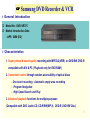
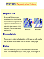
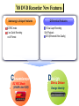
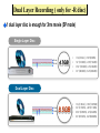
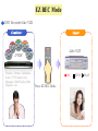
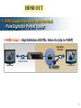
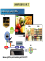
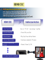
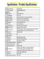
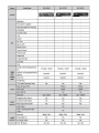
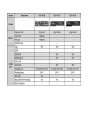
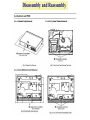
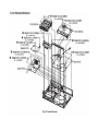
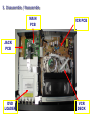
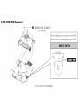
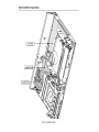
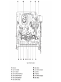
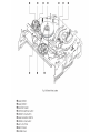
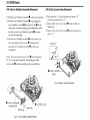
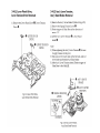
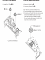
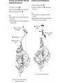
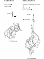
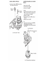
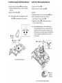
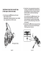
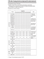
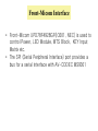
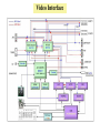
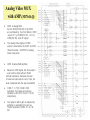
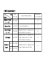
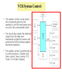
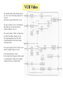
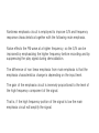
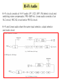
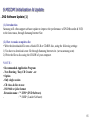
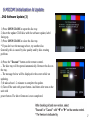
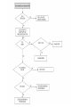
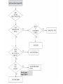
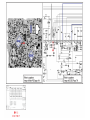
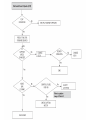
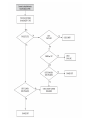
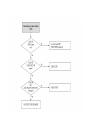
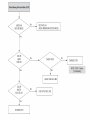
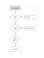
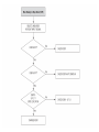
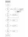
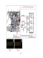
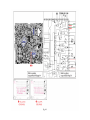
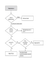
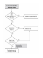
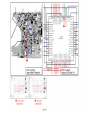
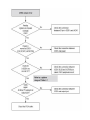
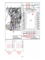
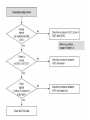
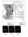
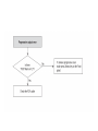
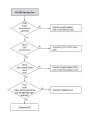
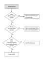
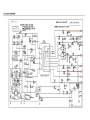
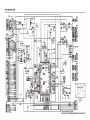
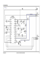
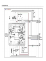
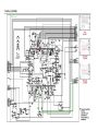
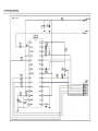
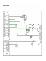
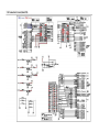
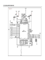
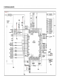
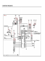
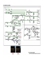
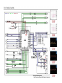
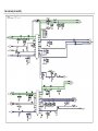
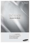
Introducing Samsung DVD Recorder & VCR ( DVD-VR375 ) 2008.2. Samsung Electronics Co. LTD Digital AV Division ☞ Samsung DVD Recorder & VCR General Introduction Model No : DVD-VR375 Market Introduction Date : APR 2008 (EU) Characteristics 1. Super picture & sound quality recording with MPEG-2(VBR) on DVD-RW, DVD-R compatible with A/V & PC ( Playback only for DVD-RAM ) 2. Convenient control through random accessibility of optical discs - One touch recording : Automatic empty area recording - Program Navigation - High Speed Search and Play 3. Advanced playback functions for multiple purposes (Compatible with DVD, Audio-CD, CD-R/RW(MP-3), DVD-R, DVD-RW Disc) 2 DVD-VR375 Playback & other Features ■ Progressive Scan By scanning all 576 lines in one pass, progressive scanning provides high vertical resolution and flicker-free, high-density image output that does not suffer from the loss of quality during subject movement -- which is characteristic of the conventional interlaced scanning method. 30 Frame/Sec 60 Frame/Sec ■ Program Navigator Recorded programs are shown as thumbnail pictures, and information such as title, recording dates and times are displayed on menu screen. User can choose a desired program. ■ Editing Simple non-linear editing is possible on menu screen without additional editing system. User can delete part of a program or entire program, and edit program title. 3 DVD-VR375 Key Features Recording Features ■ MPEG-2 VBR(Variable Bit Rate) Recording ■ Creating a DVD video title using DVD-RW/DVD-R ■ Automated Quality Adjustment for Timer Recording ■ Copying data from a digital camcorder using a DV input jack ■ Selectable Recording Mode Playing Features ■ Progressive Scan both DVD and VCR modes ■ Program Navigation Other Features ■ Easy Editing ■ Quick Recording ■ Auto Chaptering ■ HDMI out /w up-scale - Anynet+ (HDMI CEC), up to 1080P 4 ’08 DVD Recorder New Features Samsung’s Unique Features EZ REC mode 1 sec Quick Recording on All Format L1200 Convenience EZ REC Mode (DVDR Like VCR) Differential Features -R Dual Layer Recording DivX Playback EVQ (Enhanced Video Quality) L1200 DSlim esign & Deluxe Design Identity Dual Layer Recording ( only for -R disc) 1 dual layer disc is enough for 3hrs movie (SP mode) Single Layer Disc 0.6 mm 0.6 mm 4.7GB • • • • HQ (60min), HSP(90MIN) SP (120MIN), LSP(150MIN) ESP (180MIN), LP(240MIN) EP (360MIN), SLP(480MIN) • • • • HQ (108min), HSP(162MIN) SP (217MIN), LSP(271MIN) ESP (325MIN), LP(434MIN) EP (651MIN), SLP(868MIN) Dual Layer Disc 0.6 mm 0.6 mm 8.5GB EVQ (Enhanced Video Quality) Video Noise Reduction Reduce the pixel noise, produced during Digital signal processing False Color Reduction False Color reduction filter reduces the cross color phenomenon produced by in complemented separation of Y & C signal Sharpness Enhance EZ REC Mode DVD Recorder like VCR Complicate… Simple! Like VCR DVDR Finalize, Format, Unfinalize, Select V/VR mode, Disc Manager, Edit Playlist, Edit Chapter…etc REC Press EZ REC Mode STOP PLAY EZ REC Mode DVD Recorder like VCR 1. Auto Setting for All Formats Operated in their separate ways DVD+R Initialize Finalize Format Edit DVD-RAM O - V/VR Play list DVD-RW O O V/VR Play list DVD+RW O O O Chapter DVD-R - O O - DVD+R O O O - Initialize What’s Format? Samsung DVD Recorder does setting itself for all Formats Initialize Finalize Format Edit DVD-RAM O - V/VR Play list DVD-RW O O V/VR Play list DVD+RW O O O Chapter DVD-R - O O - DVD+R O O O - There is One Format from now on Beginner Mode DVD Recorder like VCR 2. UI Identity for All formats Operated in their separate ways • Different Menu DVD+R • Different UI Scenario Initialize • Different Menu Naming Different UI for each format! Same UI to operate DVD Recorder with All Format Same Menu Same UI Scenario For All Format HDMI OUT HDMI (High Definition Multimedia Interface) - Pure Digital for Perfect Vision HDMI Output -High Definition DIGITAL Video Out (Up to 1080P) Digital Signal Processing Digital-toAnalog Converter 11 1080P HDMI OUT No More high quality! 1080p 1080p Bypass 1080i 1080p De – Interlacing 1080p Scale-Up 480p 480i 480i [DVD Title] Samsung DVD is perfect matching with Full HD TV HDMI CEC HDMI (High Definition Multimedia Interface) - 100% Digital way of AV Streaming without Loss - Up Scaled Video Output upto 1080P: Better DVD - HDMI CEC(Commands go each Devices through HDMI Cable) HDMI CEC 1) One Touch Play Intellectual Action • Disc In → TV ON → Auto Setting → AutoPlay 2) Sysetm Stand-By • Power Off by one Click 3) Deck Control • Play, Stop, Pause with Any Remote 4) Device Menu Control • Send menu command by TV remote 5) Remote Control Pass Through • Channel, Volume Up / DN ● ● ● 13) Vendor Specific Commands 13 Specification – Product Specifications Specification – Chassis Product Specifications 4. Description 21 Disassembly and Reassembly 5. Disassemble / Reassemble MAIN PCB VCR PCB JACK PCB DVD LOADER VCR DECK Front-Micom Interface • Front-Micom UPD78F4928GF(IC601, NEC) is used to control Power, LED Module, MTS Block, KEY Input Matrix etc. • The SPI (Serial Peripheral Interface) port provides a bus for a serial interface with AV-CODEC MS9301 Video Interface • MIC1 (MPEG2 Encoder/Decoder) diverges from the 13.5MHz crystal, then generates V-SYNC and H-SYNC. • MIC1 does RGB encoding, copy guard processing and D/A conversion of 10bit Video signal converted into analog signal is outputted via amplifier of analog part. MIC1 inputted from pin 131 with 13.5MHz generates HSYNC and VSYNC which are based on video signal. It is synchronous signals with decoded video signal. The above signals, which are CVBS (Composite Video Blanking Sync), Y(S_Video)/C(S_Video), Y(Component)/Cb(component)/Cr(component), R(Red)/G(Green)/B(Blue) are selectively outputted 576i(interlaced Video Output), 576P(progressive Video Output). • • • MIC1 adopts 10bit D/A converter. It performs video en-coding as well as copy protection. • IC801(MM1764) switch whole the I/O signals of jack block. This switching IC is controlled by I2C protocol between IC601(IO front micom). NTSC/PAL Video DECODER Video Decoder(SAA7138) is a high quality NTSC, PAL, and SECAM video decoder plus YPbPr component inputs designed for multimedia applications. This AVIC1 (SAA7138) includes three 10-bit high speed ADCs.con verters. and A/D conversion of 10bit analog Video signal converte d into Digital Video signal (ITU-R656 Format) is outputted via On CVBS inputs, the user can control video characteristics such a s contrast, Brightness, saturation, and hue via an I2C DIC1 port in terface. A built-in versatile VBI slice and VBI data pass-through capability support common data services (VPS/PDC, auto clock search) Analog Video MUX with AMP.(M1764AQ) IC801 is analog MUX. As SCL,SDA[Pin 38,39] of the IC801 are controlled by the Front Micom, IC801 select AV 1 of CVBS[Pin 56] , AV 2 of CVBS[Pin 58] and RF signal. The analog Video Signal of IC801 output is selected by the IC601 via AVIC1 (Video Decoder : SAA7138) of analog Video input parts. IC801 includes 6dB amplifier. Based on CVBS signal, the final output l evel must be 2Vpp without 75ohm terminal resistance. Because the level of video encoder output is only 1Vpp, the level is adjusted with the special amplifier . CVBS, Y, C, Y(R), Cb(B), Cr(R) outputted from video encoder are inputted to AVIC1[Pin 2,8,6,11,14,16] respectively. The signal to which gain is adjusted by amplifier is outputted from jack via 75ohm Resistance (VR30, 31, 32, 33, 34). Audio Interface AUDIO 1.Input block DVD-VR375 has two stereo line input terminals and internal TV-audio from RF Tuner Block. These three analog audio signal sources are converted to digital data by Input Block. Input block has a Multiplexer (IC801), A/D converter inner AV-codec. IC801 change it’s output by selection control signal from IC601(front micom). 2.Output Block DVD-VR375 has two stereo analog line out terminals and one digital output terminal. Decoded signal by MIC1 is inputted to AVIC1 (D/A converter inner video decoder) then filtered and amplified by AIC4(OP-AMP). And the digital audio signal (SPDIF) is outputted in Coaxial terminal. Stereo/Bilingual (MTS inner Video decoder,SAA7138) summary 1) MTS SIGNAL : MONO(L+R),STEREO(L,R),MONO+SAP,STEREO+SAP 2) SAP : Sub Audio Program Signal (American MTS system only) < MTS system base-band spectrum > (KHz) 50 주 파 수 편 이 AM-DBS-SC L-R dbx-TV NR 25 Sub Audio Program Signal ↓ FM L+R 15 50~15KHz 5 3 0 SAP dbx-TV NR Pilot ↙ fh FM 10KHz 50~10KHz 2fh 3fh 4fh 5fh Telemetry Signal ↓ 6fh 6.5fh < MTS signal table > item Signal freq. Band signal Monaural Signal ( L + R ) Stereo Pilot Stereo Signal ( L - R ) Signal Processing System 50Hz~15KHz 15.734 KHz 50Hz~15KHz Maximum Audio Carrier dev(KHz) 25 Only Stereo Broadcasting AM modulation(Carrier frequency 2fh) dbx Noise Reduction processing 5 50 FM modulation(Carrier frequency 5fh) SAP Signal 50Hz~10KHz Maximum frequency deviation 10KHz) 15 dbx Noise Reduction processing Telemetry Signal Audio Data 0Hz~3.4KHz 0Hz~1.5KHz FM modulation(Carrier frequency 6.5fh) Maximum frequency deviation 3KHz) 3 Signal route 1) SIF signal from tuner (TM1) is connected to Video decoder(MTS processor block, SAA7138 33pin). *.SIF : Sound Intermediate Frequency 2) MTS processor block(Inner SAA7138) detect the stereo and sap signal and send the detecting state to front micom (IC601) by I2C data. It will display the screen by OSD. *.OSD : On Screen Display 3) MTS processor block decode the SIF signal and send the decoded audio signal to 106 pin(L out) and 107 pin(R out). 4) L out(106 pin) and R out(107 pin) of MTS processor block go to IC801 for audio processing. Tuner <Block diagram of Tuner > VCR System Control • The system control circuit inputs the commands given by the operator to set the mechanism and circuit to the commanded mode. • The circuit also inputs the detected output from the tape and mechanism protection sensor and protects the VCR and tape against abnormal operation. • The system control is performed by 4 control sections. (System and timer control, Servo control, F/S Tuner, On Screen Display). VCR Servo The servo system is divided into two loops. The cylinder servo controls the rotation of video heads and the capstan servo controls the tape speed. In addition it’s necessary to control cylinder motor, especially during trick play in 4H’D models. The cylinder servo loop controls the phase and speed of the cylinder motor. The speed is kept at a constant 1800 RPM and the phase determines the mechanical position relative to the vertical Sync signal. The capstan servo loop controls the phase and speed of the capstan motor so that the video head can trace the video track correctly. It keeps tape speed constant according to the mode (SP, SLP) during playback and recording. VCR Video The selected video input signal goes to pin 50 of Lumi /Chroma processor IC (IC301). And then it enters VIDEO AGC circuit. The gain of AGC circuit is controlled by AGC detector so that the output is constant (approx. 2Vp-p). The output signal of AGC is clamped by the FBC (Feed Back Clamp) circuit. This signal appears at pin 65, after being amplified at the internal video amp and driver. The output signal from the clamp circuit enter the detail enhancer circuit. In the detail enhancer circuit, the low level high frequency video signal is emphasized to improve the original signals frequency characteristics. Nonlinear emphasis circuit is employed to improve S/N and frequency response characteristics together with the following main emphasis. Noise effects the FM wave at a higher frequency, so the S/N can be improved by emphasizing the higher frequency before recording and by suppressing the play signal during demodulation. The difference of non linear emphasis from main emphasis is that the emphasis characteristics change is depending on the input level. The gain of the emphasis circuit is inversely proportional to the level of the high frequency component of the signal. That is, if the high frequency portion of the signal is low the main emphasis circuit will amplify the signal. Hi-Fi Audio Hi-Fi circuit consists of Hi-Fi audio LPF, VCO, BPF, FM detect circuit and switching noise compensator, PRE-AMP etc. Linear audio consists of an ALC circuit, REC EQ circuit and a PB EQ circuit. Hi-Fi and Linear audio share the same input selector, output selector and mute circuit. OSD The on screen display circuit consist of a character generator decoder, video mixer, sync separator and sync generator, sync detector circuit. The data is decoded and generates characters in syncro with composite video signal applied pin 13, 15. Also the sync detector circuit discriminates the presence of a video signal by detecting sync, if no sync is detected, a blue screen is displayed. In other word, the OSD circuit displays character on the video when there is a video signal or on blue screen when there is no video signal. (No sync). ` 9.MICOM Initialization & Update . DVD Software Update (1) (1). Introduction Samsung will often support software update to improve the performance of DVD Recorder & VCR to the latest staus, through Samsung Internet Site. (2). How to make an update disc • Write the downloaded file onto a blank CD-R or CD-RW disc, using the following settings : 1) You have to download a new file through Samsung lnternet site. (www.samsung.com) 2) Write the file to disc using the CD-RW of your computer. NOTE: • Recommended Application Program - Nero Burning / Easy CD Creator ..etc • Option - Only single session - CD close & disc at once - ISO 9660 or joliet format -Extension name : "*.UPD“ (DVD Software) : "*.SMD“ (Loader Software) 65 9.MICOM Initialization & Update . DVD Software Update (2) WARNING : It is very important : please read the below notice below before updatang your unit. The following events may interrupt the update process and MAY RESULT IN PERMANENT DAMAGE TO THE UNIT WHILE UPDATING 1. Unplugging the power cord. 2. Power Outage. 3. Dirt or Scratches on the disc. 4. Opening a disc tray during processing. 66 9.MICOM Initialization & Update . DVD Software Update (3) 1) Press OPEN/CLOSE to open the disc tray. 2) Insert the update CD-R disc with the software update, label facing up. 3) Press OPEN/CLOSE to close the disc tray. * If you don't see the message above, try another disc. Generally, this is caused by disc quality and by disc creating problem. 4) Press the "Execute" button on the remote control. -. The disc tray will be opened automatically. Remove the disc on the tray. -. The message below will be displayed n the screen while on updating. 5) It takes about 1~2 minutes to complete the update. 6) Turn off the unit with power button. And there after turn on the unit with power button. The drive firmware is now completed. 67 Troubleshooting Schematic Diagram All Block Diagram ELECTRONICS This Service Manual is a property of Samsung Electronics Co .,Ltd. Any unauthorized use of Manual can be punished under applicable International and/or domestic law. © Samsung Electronics Co., Ltd. FAB.2008 Printed in Korea