1
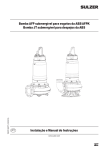
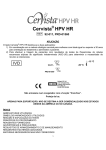
OBDII to J1587/J1708
Converter Installation and
Troubleshooting Guide
QUALCOMM Incorporated
5775 Morehouse Drive
San Diego, CA 92121-1714
U.S.A.
© 2005-2012 QUALCOMM Incorporated. All rights reserved.
Qualcomm and Qualcomm Enterprise Services are registered trademarks of QUALCOMM Incorporated in
the United States and may be registered in other countries. All other trademarks are the property of their
respective owners. Specifications are subject to change without notice. Qualcomm endeavors to ensure that
the information in this document is correct and fairly stated, but Qualcomm is not liable for any errors or
omissions. Published information may not be up to date, and it is important to confirm current status with
Qualcomm.
The MAS200 contains Adobe® Flash® Player software by Adobe Systems Incorporated, Copyright © 19962007 Adobe Systems Incorporated. All Rights Reserved. Adobe and Flash are either trademarks or registered trademarks of Adobe Systems Incorporated in the United States and/or other countries.
This technical data may be subject to U.S. and international export, re-export or transfer (export) laws.
Diversion contrary to U.S. and international law is strictly prohibited.
80-J9325-1 Rev. C
November 2012
Troubleshooting Contents
Introduction and Installation
Introduction .......................................................................................................1-1
OBDII to J1587/J1708 Converter Kit ................................................................1-2
Feature Requirements ......................................................................................1-3
Installation Precautions .....................................................................................1-3
Hardware Installation Procedures .....................................................................1-4
System Verification and Troubleshooting
System Verification ...........................................................................................2-1
Troubleshooting ................................................................................................2-2
LED Troubleshooting Table for new LDVDSV2 ..........................................2-3
LED Troubleshooting Table for J9322-1 .....................................................2-4
80-J9325-1 Rev. C
MAY CONTAIN U.S. AND INTERNATIONAL EXPORT CONTROLLED INFORMATION
Troubleshooting Contents
80-J9325-1 Rev. C
MAY CONTAIN U.S. AND INTERNATIONAL EXPORT CONTROLLED INFORMATION
1
Introduction and Installation
Introduction
The OBDII to J1587/J1708 Converter is a hardware device that can translate OBDII/J1850
light-duty vehicle data to the J1587/J1708 format. This OBDII converter allows a Qualcomm
customer to obtain Performance Monitoring data on light-duty vehicles.
The OBDII supports any 1996 or newer vehicles that comply with the SAE’s J1979 OBDII
specification. Refer to the Supported Parameters List at http://www.bb-elec.com/qualcomm
for a list of supported parameters by vehicle type.
The vehicle data received from the OBDII converter includes:
• Vehicle speed
• Engine speed
• Total distance (odometer)
• Total fuel
• Throttle position
For more detailed information regarding Performance Monitoring installations and
troubleshooting, please refer to the appropriate Qualcomm installations manual for the
product you are installing in conjunction with the OBDII converter.
80-J9325-1 Rev. C
MAY CONTAIN U.S. AND INTERNATIONAL EXPORT CONTROLLED INFORMATION
1-1
OBDII to J1587/J1708 Converter Kit
Introduction and Installation
OBDII to J1587/J1708 Converter Kit
This document supports two converter kits: LDVDSV2 is the current production. 65-J9322-1
is no longer in production.
LDVDSV2
65-J9322-1
1-2
80-J9325-1 Rev. C
MAY CONTAIN U.S. AND INTERNATIONAL EXPORT CONTROLLED INFORMATION
Introduction and Installation
Feature Requirements
Feature Requirements
• Performance Monitoring must be enabled on Qualcomm hardware.
• Qualcomm hardware should have the minimum firmware needed to support Performance
Monitoring.
• Performance Monitoring must be supported at the host.
Installation Precautions
Before you install the equipment, read the following WARNINGS:
!
WARNING
!
WARNING
Mounting the equipment near the
vehicle airbags can injure a driver
or passenger involved in a crash
Improper cable installation can
interfere with the vehicle pedals
or steering
Airbag firing can cause the equipment to become a projectile leading to serious injury or death
Interfering with the pedals or
steering can cause a crash, resulting in serious injury or death
Mount the equipment in a location
that will not be impacted by the
firing of any forward or side
airbag
Mount the cables so that they can
not interfere with the brake, accelerator, clutch, or steering wheel,
EVEN IF THE TIE WRAPS FAIL
!
DANGER
Using a test light to probe vehicle wiring can cause the
AIRBAG TO FIRE
Airbag firing while working
near the vehicle dash or steering wheel can cause serious
injury or death
Never use a test light to probe
wiring
USE VOLT-OHM METE R ONLY
80-J9325-1 Rev. C
MAY CONTAIN U.S. AND INTERNATIONAL EXPORT CONTROLLED INFORMATION
1-3
Hardware Installation Procedures
Introduction and Installation
Hardware Installation Procedures
Once the location and connection points are defined, follow these instructions:
1-4
1.
Verify that the engine ignition switch is OFF.
2.
Make the following connections:
a.
Connect the OBDII converter’s red (Data -) wire to the red
(J1587/J1708 -) wire on the Qualcomm harness.
b.
Connect the OBDII converter’s brown (Data +) wire to the brown (J1587/J1708 +)
wire on the Qualcomm harness.
c.
For 65-J9322-1 ONLY: Connect the white (Ignition) wire to the same ignition
source as the Qualcomm system. The LDVDSV2 does not have an ignition wire.
3.
Unmount the vehicle’s existing OBDII diagnostic’s connector.
4.
Locate the OBDII Y cable coming from the OBDII converter.
5.
Connect the OBDII male connector on the Y cable into the vehicle’s existing female
connector.
6.
Mount the OBDII female connector on the Y cable in place of the vehicle’s original
connector. This will make it available for use by the OEM or other third party service
providers.
7.
Secure OBDII converter box and excess cabling using tie-wraps.
80-J9325-1 Rev. C
MAY CONTAIN U.S. AND INTERNATIONAL EXPORT CONTROLLED INFORMATION
2
System Verification and Troubleshooting
System Verification
1.
Turn ignition ON.
2.
Verify that the MCP or OmniTRACS unit is configured to use J1587/J1708 data.
3.
Verify that the MCP or OmniTRACS unit is receiving all expected data items per
Supported Parameter List found on the B&B Electronics web site:www.bb-elec.com/
qualcomm.
4.
MCP50, MCP110, MCP200: Make sure the Run All Core Data Items test passes. For
more details, see the appropriate installation guide. MCP50 Installation and
Troubleshooting Guide (80-JB566-1), MCP110 Installation Guide (80-JB400-1), or
MCP200 Installation Guide (80-J9968-1).
• MCP100: Follow system verification in the MCP100 Installation Guide (80-J4866-2)
• OmniTRACS: Follow system verification in the IMCT and Accessory Installation
Guide (80-30432-1) or MCT and Accessory Installation Guide (80-30170-1).
5.
If the mobile unit is not receiving the expected data items, check the following:
• Check the LED table to ensure the converter is installed and working properly.
• Check the connections between the converter and the MCP or OmniTRACS unit.
• Check the Supported Parameter List to ensure the vehicle is compatible with the
converter.
Notes
For most installations, you should expect to see 3 (Missing Total Engine Hours), 6
(Missing Ambient Temperature), and 7 (Missing Parking Brake Status) as these data
items are not provided by the OBDII converter.
Please refer to the Supported Vehicle List for details to learn which data items are
expected for each year/make/model of vehicle. This can be found at:
www.bb-elec.com/qualcomm.
Qualcomm's Performance Monitoring Odometer screen reading may differ from the
vehicle's dash odometer reading; this is acceptable, and it is not an error condition.
Reasons for this is that the odometer value being used is from a different source than
what is displayed on the dash or possible a component on the vehicle that stores the
odometer value may have been replaced.
80-J9325-1 Rev. C
MAY CONTAIN U.S. AND INTERNATIONAL EXPORT CONTROLLED INFORMATION
2-1
Troubleshooting
System Verification and Troubleshooting
Notes
Some vehicles do not provide a life to date odometer reading on the data bus. On these
vehicles, the OBDII converter will generate a calculated odometer value. The calculated
odometer begins at zero at time of installation or when the firmware is reinstalled/
upgraded.”
OmniTRACS Product Only- The Life-To-Date Distance field may indicate “No
Equipment” when the system is first installed on a vehicle that requires the OBDII
Converter to calculate an odometer value. The “No Equipment” indication will continue
to be displayed until the computed odometer value is non-zero. In these cases, the
vehicle must be driven a short distance to allow the odometer calculation to accumulate
some distance. Once the converter begins to broadcast a non-zero value for odometer,
the Life-To-Date Distance field should begin displaying the computed value. This
situation will also occur any time the firmware is updated on a vehicle that requires the
OBDII Converter to calculate an odometer value.
Troubleshooting
The OBDII converter has two LEDs which are visible on the top of the unit. The red LED
indicates power and the green LED indicates status. Use the LEDs to diagnose various
issues. See the LED troubleshooting table on the next page.
LDVDSV2
Status LED (green)
Power LED (red)
65-J9322-1
2-2
80-J9325-1 Rev. C
MAY CONTAIN U.S. AND INTERNATIONAL EXPORT CONTROLLED INFORMATION
System Verification and Troubleshooting
LED Troubleshooting Table for new LDVDSV2
LED Troubleshooting Table for new LDVDSV2
Red LED (Power)
Green LED
(Activity)
Description
On (lit solid)
On (lit solid)
Normal operation
On (lit solid)
SB (slow blinking,
alternating on-off,
.5 sec. on
.5 sec. off)
Detecting vehicle
Off (unlit)
FB (fast blinking,
alternating on-off,
125 ms on
125 ms off)
Database needs to be updated. Return unit
for service.
Off (unlit)
VSB (very slow blinking,
alternating on-off
.25 sec. on
.25 sec. off)
Device asleep
Off (unlit)
Off (unlit)
Power on self-test. If neither LED lights in
30 seconds, check vehicle power to the
OBDII converter.
Off (unlit)
On (lit solid)
Firmware needs to be updated.
80-J9325-1 Rev. C
MAY CONTAIN U.S. AND INTERNATIONAL EXPORT CONTROLLED INFORMATION
2-3
LED Troubleshooting Table for 65-J9322-1
System Verification and Troubleshooting
LED Troubleshooting Table for 65-J9322-1
LED
Ignition
State
State
Possible Causes
Solution
Ignition OFF
Key ON/
Ignition OFF
Green flashing Any vehicle
state
Correct
Correct
n/a
n/a
Correct
n/a
Green ON
Correct
n/a
n/a
Green LED should flash in this condition during
vehicle detection, then go OFF.
Green LED should flash in this condition during
vehicle detection
It will turn OFF if engine is not running.
It will turn ON if engine is running.
n/a
Correct
Incorrect
n/a
No power from the ignition wire
to the LDVDS.
OBDII Converter power fault.
No power from the vehicle to
the LDVDS.
OBDII Converter power Fault.
Green OFF
Green OFF
Red OFF
Red OFF
Engine
running
Ignition OFF
Key ON/
Ignition OFF
Red OFF
Engine
running
Incorrect
Red flashing
2 seconds
OFF/ 0.02
seconds ON
(short blip)
Red flashing
2 seconds
OFF/ 0.02
seconds ON
(short blip)
Red flashing
2 seconds
OFF/ 0.02
seconds ON
(short blip)
Red flashing
2 seconds
OFF/ 0.5
seconds ON
Red flashing 2
seconds OFF/
0.5 seconds
ON
Red flashing
2 seconds
OFF/ 0.5
seconds ON
Ignition OFF
Correct once
engine has
been ON once
after install
(sleep)
Incorrect
2-4
Key ON/
Engine OFF
Note: May not see short blip
Check power wiring from the vehicle to the
OBDII Converter.
Check fuses on the vehicle.
Swap OBDII Converter with a known good
device; replace device if appropriate.
Check power wiring from the vehicle to the
LDVDS.
Check fuses on the vehicle.
Swap OBDII Converter with a known good
device; replace device if appropriate.
OBDII Converter host
processor fault.
Swap OBDII Converter with a known good
device; replace device if appropriate.
OBDII Converter host
processor fault.
Swap OBDII Converter with a known good
device; replace device if appropriate.
Engine
Running
Incorrect
Key ON/
Engine OFF
Correct
Ignition OFF
Incorrect
Power wired to VBat instead of
switched ignition.
OBDII Converter fault
Engine
running
Incorrect
No power on the vehicle OBDII
connector.
OBDII Converter fault.
The OBDII Converter is polling for RPM>0.
Check that there is no 12V on the ignition wire
going to the OBDII Converter.
Swap OBDII Converter with a known good
device; replace device if appropriate.
Check power on the vehicle OBDII connector.
Check fuses on the vehicle.
Swap OBDII Converter with a known good
device; replace device if appropriate.
80-J9325-1 Rev. C
MAY CONTAIN U.S. AND INTERNATIONAL EXPORT CONTROLLED INFORMATION
System Verification and Troubleshooting
LED
Ignition
State
Red ON
Engine
running
Red ON
Key ON/
Engine OFF
Red ON
Ignition OFF
Red flashing
0.5 seconds
OFF/2
seconds ON
any
LED Troubleshooting Table for 65-J9322-1
State
Possible Causes
Solution
Correct if
Green LED is
also ON
Incorrect on all
but Sprinter
n/a
n/a
Vehicle not detected yet.
No data on OBDII connector.
OBDII Converter fault.
Correct for
initial install
before engine
has started.
Detecting
vehicle
incorrect
Vehicle does not support
OBDII.
Loose connections on OBDII
Converter connector.
OBDII Converter fault.
Wait at least 30 seconds in this state for the
OBDII Converter to detect vehicle parameters.
Check data using another scan tool.
Swap OBDII Converter with a known good
device; replace device if appropriate.
Verify vehicle make/model/year are supported
by the firmware.
Check communications with OEM scan tool
Swap OBDII Converter with a known good
device; replace device if appropriate.
OBDII Converter fault
Swap OBDII Converter with a known good
device; replace device if appropriate
For additional support, call QES Customer Support at (800) 541-7490.
80-J9325-1 Rev. C
MAY CONTAIN U.S. AND INTERNATIONAL EXPORT CONTROLLED INFORMATION
2-5
LED Troubleshooting Table for 65-J9322-1
2-6
System Verification and Troubleshooting
80-J9325-1 Rev. C
MAY CONTAIN U.S. AND INTERNATIONAL EXPORT CONTROLLED INFORMATION