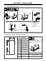
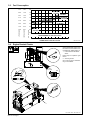
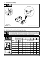
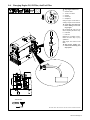
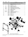
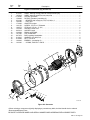
1
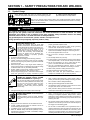
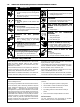
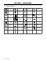
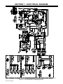
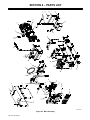
January 1997 Form: OM-175 104B Effective With Serial No. KG191348 OWNER’S MANUAL Bobcat 225G (Kohler-Powered) CC/CV AC/DC Welding Generator For SMAW, FCAW, GMAW, GTAW Welding Welding Mode Weld Output Range Rated Welding Output Maximum Open-Circu it Voltage CC/AC 50 – 225 A 225 A, 25 V, 100% Duty Cycle 80 CC/DC 50 – 210 A 210 A, 25 V, 100% Duty Cycle 72 CV/DC 17 – 28 V 200 A, 20 V, 100% Duty Cycle 33 cover_om 4/95 – Ref. ST-801 188-A Auxiliary Power Rating Fuel Capacity Engine Single-Phase, 8 kVA/kW, 70/35 A, 120/240 V AC, 60 Hz 8.5 gal (32 L) Tank Kohler CH18 Air-Cooled, Two-Cylinder, Four-Cycle, 18 HP Gasoline Engine 1997 MILLER Electric Mfg. Co. PRINTED IN USA TABLE OF CONTENTS SECTION 1 – SAFETY PRECAUTIONS FOR ARC WELDING . . . . . . . . . . . . . . . . . . . . . . . . . . . . . . . . . 1-1. Symbol Usage . . . . . . . . . . . . . . . . . . . . . . . . . . . . . . . . . . . . . . . . . . . . . . . . . . . . . . . . . . . . . . . . . 1-2. Arc Welding Hazards . . . . . . . . . . . . . . . . . . . . . . . . . . . . . . . . . . . . . . . . . . . . . . . . . . . . . . . . . . . . 1-3. Engine Hazards . . . . . . . . . . . . . . . . . . . . . . . . . . . . . . . . . . . . . . . . . . . . . . . . . . . . . . . . . . . . . . . . 1-4. Additional Installation, Operation, And Maintenance Hazards . . . . . . . . . . . . . . . . . . . . . . . . . 1-5. Principal Safety Standards . . . . . . . . . . . . . . . . . . . . . . . . . . . . . . . . . . . . . . . . . . . . . . . . . . . . . . . 1-6. EMF Information . . . . . . . . . . . . . . . . . . . . . . . . . . . . . . . . . . . . . . . . . . . . . . . . . . . . . . . . . . . . . . . 1 1 1 2 3 3 3 SECTION 2 – DEFINITIONS . . . . . . . . . . . . . . . . . . . . . . . . . . . . . . . . . . . . . . . . . . . . . . . . . . . . . . . . . . . . . . . 2-1. Symbol Definitions . . . . . . . . . . . . . . . . . . . . . . . . . . . . . . . . . . . . . . . . . . . . . . . . . . . . . . . . . . . . . . 4 4 SECTION 3 – INSTALLATION . . . . . . . . . . . . . . . . . . . . . . . . . . . . . . . . . . . . . . . . . . . . . . . . . . . . . . . . . . . . . 5 3-1. 3-2. 3-3. 3-4. 3-5. 3-6. Installing Welding Generator . . . . . . . . . . . . . . . . . . . . . . . . . . . . . . . . . . . . . . . . . . . . . . . . . . . . . Dimensions, Weights, And Operating Angles . . . . . . . . . . . . . . . . . . . . . . . . . . . . . . . . . . . . . . . Fuel Consumption . . . . . . . . . . . . . . . . . . . . . . . . . . . . . . . . . . . . . . . . . . . . . . . . . . . . . . . . . . . . . . Engine Prestart Checks . . . . . . . . . . . . . . . . . . . . . . . . . . . . . . . . . . . . . . . . . . . . . . . . . . . . . . . . . Connecting The Battery . . . . . . . . . . . . . . . . . . . . . . . . . . . . . . . . . . . . . . . . . . . . . . . . . . . . . . . . . Weld Output Terminals And Selecting Cable Sizes . . . . . . . . . . . . . . . . . . . . . . . . . . . . . . . . . . 5 5 6 6 7 7 SECTION 4 – OPERATING WELDING GENERATOR . . . . . . . . . . . . . . . . . . . . . . . . . . . . . . . . . . . . . . . . . 8 4-1. 4-2. Front Panel Controls . . . . . . . . . . . . . . . . . . . . . . . . . . . . . . . . . . . . . . . . . . . . . . . . . . . . . . . . . . . . Duty Cycle . . . . . . . . . . . . . . . . . . . . . . . . . . . . . . . . . . . . . . . . . . . . . . . . . . . . . . . . . . . . . . . . . . . . . 8 9 SECTION 5 – OPERATING AUXILIARY EQUIPMENT . . . . . . . . . . . . . . . . . . . . . . . . . . . . . . . . . . . . . . . . 5-1. Standard Receptacles . . . . . . . . . . . . . . . . . . . . . . . . . . . . . . . . . . . . . . . . . . . . . . . . . . . . . . . . . . . 5-2. Optional Auxiliary Power Receptacles . . . . . . . . . . . . . . . . . . . . . . . . . . . . . . . . . . . . . . . . . . . . . 5-3. Wiring Optional 240 Volt Plug . . . . . . . . . . . . . . . . . . . . . . . . . . . . . . . . . . . . . . . . . . . . . . . . . . . . 10 10 11 12 SECTION 6 – MAINTENANCE AND TROUBLESHOOTING . . . . . . . . . . . . . . . . . . . . . . . . . . . . . . . . . . . 6-1. Routine Maintenance . . . . . . . . . . . . . . . . . . . . . . . . . . . . . . . . . . . . . . . . . . . . . . . . . . . . . . . . . . . 6-2. Maintenance Label . . . . . . . . . . . . . . . . . . . . . . . . . . . . . . . . . . . . . . . . . . . . . . . . . . . . . . . . . . . . . 6-3. Servicing Air Cleaner . . . . . . . . . . . . . . . . . . . . . . . . . . . . . . . . . . . . . . . . . . . . . . . . . . . . . . . . . . . 6-4. Changing Engine Oil, Oil Filter, And Fuel Filter . . . . . . . . . . . . . . . . . . . . . . . . . . . . . . . . . . . . . 6-5. Adjusting Engine Speed . . . . . . . . . . . . . . . . . . . . . . . . . . . . . . . . . . . . . . . . . . . . . . . . . . . . . . . . . 6-6. Overload Protection . . . . . . . . . . . . . . . . . . . . . . . . . . . . . . . . . . . . . . . . . . . . . . . . . . . . . . . . . . . . . 6-7. Inspecting And Cleaning Optional Spark Arrestor . . . . . . . . . . . . . . . . . . . . . . . . . . . . . . . . . . . 6-8. Troubleshooting . . . . . . . . . . . . . . . . . . . . . . . . . . . . . . . . . . . . . . . . . . . . . . . . . . . . . . . . . . . . . . . . 13 13 14 14 15 16 17 17 18 SECTION 7 – ELECTRICAL DIAGRAM . . . . . . . . . . . . . . . . . . . . . . . . . . . . . . . . . . . . . . . . . . . . . . . . . . . . . 20 SECTION 8 – PARTS LIST . . . . . . . . . . . . . . . . . . . . . . . . . . . . . . . . . . . . . . . . . . . . . . . . . . . . . . . . . . . . . . . . 21 OM-175 104B – 1/97 SECTION 1 – SAFETY PRECAUTIONS FOR ARC WELDING safety_rom1 4/95 1-1. Symbol Usage Means Warning! Watch Out! There are possible hazards with this procedure! The possible hazards are shown in the adjoining symbols. Y Marks a special safety message. . Means NOTE; not safety related. This group of symbols means Warning! Watch Out! possible ELECTRIC SHOCK, MOVING PARTS, and HOT PARTS hazards. Consult symbols and related instructions below for necessary actions to avoid the hazards. 1-2. Arc Welding Hazards WARNING The symbols shown below are used throughout this manual to call attention to and identify possible hazards. When you see the symbol, watch out, and follow the related instructions to avoid the hazard. The safety information given below is only a summary of the more complete safety information found in the Safety Standards listed in Section 1-5. Read and follow all Safety Standards. Only qualified persons should install, operate, maintain, and repair this unit. During operation, keep everybody, especially children, away. ELECTRIC SHOCK can kill. 1. 2. 3. 4. 5. 6. Touching live electrical parts can cause fatal shocks or severe burns. The electrode and work circuit is electrically live whenever the output is on. The input power circuit and machine internal circuits are also live when power is on. In semiautomatic or automatic wire welding, the wire, wire reel, drive roll housing, and all metal parts touching the welding wire are electrically live. Incorrectly installed or improperly grounded equipment is a hazard. Do not touch live electrical parts. Wear dry, hole-free insulating gloves and body protection. Insulate yourself from work and ground using dry insulating mats or covers big enough to prevent any physical contact with the work or ground. Disconnect input power or stop engine before installing or servicing this equipment. Lockout/tagout input power according to OSHA 29 CFR 1910.147 (see Safety Standards). Properly install and ground this equipment according to its Owner’s Manual and national, state, and local codes. Always verify the supply ground – check and be sure that input power cord ground wire is properly connected to ground ARC RAYS can burn eyes and skin; NOISE can damage hearing; FLYING SLAG OR SPARKS can injure eyes. Arc rays from the welding process produce intense visible and invisible (ultraviolet and infrared) rays that can burn eyes and skin. Noise from some processes can damage hearing. Chipping, grinding, and welds cooling throw off pieces of metal or slag. NOISE 1. Use approved ear plugs or ear muffs if noise level is high. FUMES AND GASES can be hazardous to your health. Welding produces fumes and gases. Breathing these fumes and gases can be hazardous to your health. 1. Keep your head out of the fumes. Do not breathe the fumes. 2. If inside, ventilate the area and/or use exhaust at the arc to remove welding fumes and gases. 3. If ventilation is poor, use an approved air-supplied respirator. 4. Read the Material Safety Data Sheets (MSDSs) and the manufacturer’s instruction for metals, consumables, coatings, cleaners, and degreasers. 7. 8. 9. 10. 11. 12. 13. 14. 15. 16. 17. terminal in disconnect box or that cord plug is connected to a properly grounded receptacle outlet. When making input connections, attach proper grounding conductor first – double-check connections. Frequently inspect input power cord for damage or bare wiring – replace cord immediately if damaged – bare wiring can kill. Turn off all equipment when not in use. Do not use worn, damaged, undersized, or poorly spliced cables. Do not drape cables over your body. If earth grounding of the workpiece is required, ground it directly with a separate cable – do not use work clamp or work cable. Do not touch electrode if you are in contact with the work, ground, or another electrode from a different machine. Use only well-maintained equipment. Repair or replace damaged parts at once. Maintain unit according to manual. Wear a safety harness if working above floor level. Keep all panels and covers securely in place. Clamp work cable with good metal-to-metal contact to workpiece or worktable as near the weld as practical. ARC RAYS 2. Wear a welding helmet fitted with a proper shade of filter to protect your face and eyes when welding or watching (see ANSI Z49.1 and Z87.1 listed in Safety Standards). 3. Wear approved safety glasses with side shields. 4. Use protective screens or barriers to protect others from flash and glare; warn others not to watch the arc. 5. Wear protective clothing made from durable, flame-resistant material (wool and leather) and foot protection. 5. Work in a confined space only if it is well ventilated, or while wearing an air-supplied respirator. Always have a trained watchperson nearby. Welding fumes and gases can displace air and lower the oxygen level causing injury or death. Be sure the breathing air is safe. 6. Do not weld in locations near degreasing, cleaning, or spraying operations. The heat and rays of the arc can react with vapors to form highly toxic and irritating gases. 7. Do not weld on coated metals, such as galvanized, lead, or cadmium plated steel, unless the coating is removed from the weld area, the area is well ventilated, and if necessary, while wearing an air-supplied respirator. The coatings and any metals containing these elements can give off toxic fumes if welded. OM-175 104 Page 1 CYLINDERS can explode if damaged. Shielding gas cylinders contain gas under high pressure. If damaged, a cylinder can explode. Since gas cylinders are normally part of the welding process, be sure to treat them carefully. 1. Protect compressed gas cylinders from excessive heat, mechanical shocks, slag, open flames, sparks, and arcs. 2. Install cylinders in an upright position by securing to a stationary support or cylinder rack to prevent falling or tipping. 3. Keep cylinders away from any welding or other electrical circuits. WELDING can cause fire or explosion. Welding on closed containers, such as tanks, drums, or pipes, can cause them to blow up. Sparks can fly off from the welding arc. The flying sparks, hot workpiece, and hot equipment can cause fires and burns. Accidental contact of electrode to metal objects can cause sparks, explosion, overheating, or fire. Check and be sure the area is safe before doing any welding. 1. Protect yourself and others from flying sparks and hot metal. 2. Do not weld where flying sparks can strike flammable material. 3. Remove all flammables within 35 ft (10.7 m) of the welding arc. If this is not possible, tightly cover them with approved covers. 4. Be alert that welding sparks and hot materials from welding can easily go through small cracks and openings to adjacent areas. 5. Watch for fire, and keep a fire extinguisher nearby. Never drape a welding torch over a gas cylinder. Never allow a welding electrode to touch any cylinder. Never weld on a pressurized cylinder – explosion will result. Use only correct shielding gas cylinders, regulators, hoses, and fittings designed for the specific application; maintain them and associated parts in good condition. 8. Turn face away from valve outlet when opening cylinder valve. 9. Keep protective cap in place over valve except when cylinder is in use or connected for use. 10. Read and follow instructions on compressed gas cylinders, associated equipment, and CGA publication P-1 listed in Safety Standards. 4. 5. 6. 7. 6. Be aware that welding on a ceiling, floor, bulkhead, or partition can cause fire on the hidden side. 7. Do not weld on closed containers such as tanks, drums, or pipes, unless they are properly prepared according to AWS F4.1 (see Safety Standards). 8. Connect work cable to the work as close to the welding area as practical to prevent welding current from traveling long, possibly unknown paths and causing electric shock and fire hazards. 9. Do not use welder to thaw frozen pipes. 10. Remove stick electrode from holder or cut off welding wire at contact tip when not in use. 11. Wear oil-free protective garments such as leather gloves, heavy shirt, cuffless trousers, high shoes, and a cap. 12. Remove any combustibles, such as a butane lighter or matches, from your person before doing any welding. 1-3. Engine Hazards WARNING ENGINE EXHAUST GASES can kill. Engines produce harmful exhaust gases. 1. Use equipment outside in open, well-ventilated areas. 2. If used in a closed area, vent engine exhaust outside and away from any building air intakes. ENGINE FUEL can cause fire or explosion. 2. Do not add fuel while smoking or if unit is near any sparks or open flames. Engine fuel is highly flammable. 3. Do not overfill tank – allow room for fuel to expand. 1. Stop engine and let it cool off before checking or adding fuel. MOVING PARTS can cause injury. Moving parts, such as fans, rotors, and belts can cut fingers and hands and catch loose clothing. 1. Keep all doors, panels, covers, and guards closed and securely in place. 2. Stop engine before installing or connecting unit. SPARKS can cause BATTERY GASES TO EXPLODE; BATTERY ACID can burn eyes and skin. Batteries contain acid and generate explosive gases. STEAM AND PRESSURIZED HOT COOLANT can burn face, eyes, and skin. It is best to check coolant level when engine is cold to avoid scalding. OM-175 104 Page 2 4. Do not spill fuel. If fuel is spilled, clean up before starting engine. 3. Have only qualified people remove guards or covers for maintenance and troubleshooting as necessary. 4. To prevent accidental starting during servicing, disconnect negative (–) battery cable from battery. 5. Keep hands, hair, loose clothing, and tools away from moving parts. 6. Reinstall panels or guards and close doors when servicing is finished and before starting engine. 1. Always wear a face shield when working on a battery. 2. Stop engine before disconnecting or connecting battery cables. 3. Do not allow tools to cause sparks when working on a battery. 4. Do not use welder to charge batteries or jump start vehicles. 5. Observe correct polarity (+ and –) on batteries. 1. If the engine is warm and checking is needed, follow steps 2 and 3. 2. Wear safety glasses and gloves and put a rag over cap. 3. Turn cap slightly and let pressure escape slowly before completely removing cap. 1-4. Additional Installation, Operation, And Maintenance Hazards WARNING MOVING PARTS can cause injury. READ INSTRUCTIONS. 1. Before working of generator, remove spark plugs or injectors to keep engine from kicking back or starting. 2. Block flywheel so that it will not turn while working on generator components. 1. Use only genuine MILLER replacement parts. 2. Reinstall injectors and bleed air from fuel system according to engine manual. DO NOT LET ENGINE EXHAUST SPARKS CAUSE FIRE. FLYING PIECES OF METAL or DIRT can injure eyes. 1. Use approved engine exhaust spark arrestor in required areas – see applicable codes. 1. Wear safety glasses with side shields or face shield. LOW VOLTAGE AND FREQUENCY CAN DAMAGE electrical equipment such as MOTORS. STATIC ELECTRICITY can damage parts on circuit boards. 1. Put on grounded wrist strap BEFORE handling boards or parts. 2. Use proper static-proof bags and boxes to store, move, or ship PC boards. MAGNETIC CURRENTS operation. 1. Turn off or unplug equipment before starting or stopping engine. OVERUSE can EQUIPMENT. FIELDS FROM HIGH can affect pacemaker cause OVERHEATED 1. Allow cooling period. 2. Reduce current or reduce duty cycle before starting to weld again. 3. Follow rated duty cycle. 1. Pacemaker wearers keep away. 2. Wearers should consult their doctor before going near arc welding, gouging, or spot welding operations. TILTING OF TRAILER can cause injury. HOT PARTS can cause severe burns. 1. Use tongue jack or blocks to support weight. 2. Properly install welding generator onto trailer according to instructions supplied with trailer. 1. .Allow cooling period before maintaining. 2. Wear protective gloves and clothing when working on a hot engine. BATTERY ACID can BURN SKIN AND EYES. FALLING EQUIPMENT can cause serious personal injury and equipment damage. 1. Do not tip. 2. Replace damaged battery. 3. Flush eyes and skin immediately with water. 1. Use lifting eye to lift unit only, NOT running gear, gas cylinders, or any other accessories. 2. Use equipment of adequate capacity to lift unit. 1-5. Principal Safety Standards Safety in Welding and Cutting, ANSI Standard Z49.1, from American Welding Society, 550 N.W. LeJeune Rd, Miami FL 33126 Safety and Health Standards, OSHA 29 CFR 1910, from Superintendent of Documents, U.S. Government Printing Office, Washington, D.C. 20402. Safe Handling of Compressed Gases in Cylinders, CGA Pamphlet P-1, from Compressed Gas Association, 1235 Jefferson Davis Highway, Suite 501, Arlington, VA 22202. Code for Safety in Welding and Cutting, CSA Standard W117.2, from Canadian Standards Association, Standards Sales, 178 Rexdale Boulevard, Rexdale, Ontario, Canada M9W 1R3. Recommended Safe Practices for the Preparation for Welding and Cutting of Containers That Have Held Hazardous Substances, American Welding Society Standard AWS F4.1, from American Welding Society, 550 N.W. LeJeune Rd, Miami, FL 33126 Safe Practices For Occupation And Educational Eye And Face Protection, ANSI Standard Z87.1, from American National Standards Institute, 1430 Broadway, New York, NY 10018. National Electrical Code, NFPA Standard 70, from National Fire Protection Association, Batterymarch Park, Quincy, MA 02269. Cutting And Welding Processes, NFPA Standard 51B, from National Fire Protection Association, Batterymarch Park, Quincy, MA 02269. 1-6. EMF Information Considerations About Welding And The Effects Of Low Frequency Electric And Magnetic Fields The following is a quotation from the General Conclusions Section of the U.S. Congress, Office of Technology Assessment, Biological Effects of Power Frequency Electric & Magnetic Fields – Background Paper, OTA-BP-E-53 (Washington, DC: U.S. Government Printing Office, May 1989): “. . . there is now a very large volume of scientific findings based on experiments at the cellular level and from studies with animals and people which clearly establish that low frequency magnetic fields can interact with, and produce changes in, biological systems. While most of this work is of very high quality, the results are complex. Current scientific understanding does not yet allow us to interpret the evidence in a single coherent framework. Even more frustrating, it does not yet allow us to draw definite conclusions about questions of possible risk or to offer clear science-based advice on strategies to minimize or avoid potential risks.” To reduce magnetic fields in the workplace, use the following procedures: 1. Keep cables close together by twisting or taping them. 2. Arrange cables to one side and away from the operator. 3. Do not coil or drape cables around the body. 4. Keep welding power source and cables as far away as practical. 5. Connect work clamp to workpiece as close to the weld as possible. About Pacemakers: The above procedures are also recommended for pacemaker wearers. Consult your doctor for complete information. OM-175 104 Page 3 SECTION 2 – DEFINITIONS 2-1. Symbol Definitions Stop Engine Fast (Run, Weld/Power) Start Engine Read Operator’s Manual Engine Oil Fuel Battery (Engine) Engine Engine Choke Check Valve Clearance Do not switch while welding Work Connection Positive Negative Alternating Current (AC) Output Welding Arc (Electrode) Gas Metal Arc Welding (GMAW), Wire Shielded Metal Arc Welding (SMAW), Stick Gas Tungsten Arc Welding (TIG) Hours Seconds Time Protective Earth (Ground) Temperature Circuit Breaker h OM-175 104 Page 4 s Fast/Slow (Run/Idle) A Amperes Slow (Idle) V Volts SECTION 3 – INSTALLATION 3-1. Installing Welding Generator Movement Airflow Clearance Location 18 in (460 mm) 18 in (460 mm) 18 in (460 mm) OR OR 18 in (460 mm) 18 in (460 mm) Grounding 1 2 3 3 1 4 GND/PE 4 OR Use #10 AWG or larger insulated copper wire. Electrically bond generator frame to vehicle frame by metal-to-metal contact. 2 Generator Base Metal Vehicle Frame Equipment Grounding Terminal Grounding Cable 2 install1* 3/96 – Ref. ST-800 652 / Ref. ST-800 477-A / ST-158 936-A / S-0854 3-2. Dimensions, Weights, And Operating Angles Dimensions A B Height C 31 in (787 mm) Do not exceed operating angles while running i or engine i damage d will ill occur. D G 4 Holes Width 18-3/4 in (476 mm) Depth 46 in (1164 mm) A 18 in (457 mm) B 16-1/2 in (419 mm) C 3/4 in (19 mm) D 3-1/8 in (79 mm) Do not move or operate unit where it could tip tip. E 25° F 25° 25° 25° angles_1 3/96 Engine End ST-800 426 E 32-3/4 in (832 mm) Weight F 45-1/2 in (1156 mm) Net: 567 lb (258 kg) G 13/32 in (10 mm) Dia. Ship: 608 lb (276 kg) OM-175 104 Page 5 3-3. Fuel Consumption 6.62 1.46 1.8 5.67 1.25 1.5 4.73 1.04 1.3 3.78 0.84 1.0 2.84 0.63 0.8 1.89 0.42 0.5 0.95 0.21 0.3 U.S. GAL/HR. 2.0 IMP. GAS/HR. 1.67 LITERS/HR. 7.57 0.0 AUX POWER 3750 RPM DC WELD 3750 RPM AC WELD 3750 RPM CV WELD 3750 RPM IDLE 2200 RPM 0 25 50 75 100 125 150 175 200 225 250 275 WELD AMPERES AT 100% DUTY CYCLE 0 1.0 2.0 3.0 4.0 5.0 6.0 7.0 8.0 9.0 POWER KVA AT 100% DUTY CYCLE 10.0 11.0 Ref. SB-179 939 3-4. Engine Prestart Checks Check all fluids daily. Engine must be cold and on a level surface. Unit is shipped with 10W30 engine oil. 1 Low Oil Pressure Shutdown Switch Engine stops if oil pressure gets too low. Full 2 Anti-Icing Control Use control to prevent carburetor icing in cold weather. 1/2 in (13 mm) 2 Below Above Full Gasoline 45°F (7°C) 1 Ref. ST-801 188-A / Ref. ST-801 221 OM-175 104 Page 6 3-5. Connecting The Battery Connect (–) cable last. – + Tools Needed: 3/8, 1/2 in Ref. ST-800 394-B / Ref. ST-178 079-A / Ref. S-0756-D 3-6. Weld Output Terminals And Selecting Cable Sizes ARC WELDING can cause Electromagnetic Interference. To reduce possible interference, keep weld cables as short as possible, close together, and down low, such as on the floor. Locate welding operation 100 meters from any sensitive electronic equipment. Be sure this welding machine is installed and grounded according to this manual. If interference still occurs, the user must take extra measures such as moving the welding machine, using shielded cables, using line filters, or shielding the work area. Total Cable (Copper) Length In Weld Circuit Not Exceeding 100 ft (30 m) Or Less Weld Output Terminals WORK ELECTRODE 150 ft (45 m) 200 ft (60 m) 250 ft (70 m) 300 ft (90 m) 350 ft (105 m) 400 ft (120 m) Welding Amperes 10 – 60% Duty Cycle 60 – 100% Duty Cycle 100 4 4 4 3 2 1 1/0 1/0 150 3 3 2 1 1/0 2/0 3/0 3/0 200 3 2 1 1/0 2/0 3/0 4/0 4/0 250 2 1 1/0 2/0 3/0 4/0 2-2/0 2-2/0 300 1 1/0 2/0 3/0 4/0 2-2/0 2-3/0 2-3/0 350 1/0 2/0 3/0 4/0 2-2/0 2-3/0 2-3/0 2-4/0 10 – 100% Duty Cycle ST-800 396-A Weld cable size (AWG) is based on either a 4 volts or less drop or a current density of at least 300 circular mils per ampere. S-0007-D OM-175 104 Page 7 SECTION 4 – OPERATING WELDING GENERATOR 4-1. Front Panel Controls 4 5 1 6 2 3 Ref. ST-178 079-A 1 Engine Control Switch Use switch to start engine, select speed, and stop engine. In Run/Idle position, engine runs at idle speed at no load, and weld/ power speed under load. In Run position, engine runs at weld/power speed. gine starts. Do not crank engine if engine is still turning. Set anti-icing control (see Section 3-4). Place switch in Run position to operate most GMAW equipment. 2 Engine Choke Control Use control to change engine air-fuel mix. Use switch to select type of weld output. To Start: pull out choke and turn Engine Control switch to Start position. Release switch and slowly push choke in when en- OM-175 104 Page 8 To Stop: turn Engine Control switch to Off position. 3 Weld Process Selector Switch Use a positive (+) position for Direct Current Electrode Positive (DCEP) and a negative (–) position for Direct Current Electrode Negative (DCEN). Use AC position for alternating current. 4 Coarse Adjust Switch Use switch to select weld amperage range when Weld Process Selector switch is in Stick/Tig position, or voltage range when switch is in Wire position. For best arc starts, use lowest amperage range possible. 5 Fine Adjust Control Use control to select weld amperage (Stick/ Tig) or voltage (Wire) within the range selected by the Coarse Adjust switch. Control may be adjusted while welding. Weld output would be 110 A DC based on control settings shown (50% of 70 to 150 A). 6 Engine Hour Meter 4-2. Duty Cycle Duty cycle is the percentage of 10 minutes that unit can weld at rated load without overheating. Exceeding duty cycle can damage unit and void warranty. 100% Duty Cycle at 225 Amperes AC, 210 Amperes CC/DC, 200 Amperes CV/DC Continuous Welding SB-119 454-A OM-175 104 Page 9 SECTION 5 – OPERATING AUXILIARY EQUIPMENT 5-1. Standard Receptacles Auxiliary power decreases as weld current increases. Set Fine Adjust control R1 at 10 for full auxiliary power. 1 3 GFCI-2 and GFCI-3 supply 60 Hz single-phase power at weld/power speed. Maximum output from each receptacle is 2.4 kVA/kW (CSA: 1.8 kVA/kW). 4 1 2 120 V 15 A AC Receptacles GFCI-2 And GFCI-3 If a ground fault is detected, Reset button pops out and the circuit opens to disconnect the faulty equipment. Check for faulty tools, cords, etc. connected to the receptacle. Press reset button to resume operation. At least once a month, run engine at weld/power speed and press Test button to verify GFCI is working properly. 2 240 V 50 A AC Receptacle RC1 RC1 supplies 60 Hz single-phase power at weld/power speed. Maximum output is 8 kVA/kW. 3 Circuit Breakers CB1 And CB2 CB1 and CB2 protect RC1 from overload. If CB1 or CB2 opens, RC1 and one of the 120 volt receptacles does not work. 120 volts may still be present at RC1. 4 Circuit Breakers CB3 And CB4 CB3 and CB4 protect GFCI-2 and GFCI-3 from overload. If CB3 or CB4 opens, the receptacle does not work. If a circuit breaker continues to open, contact a Factory Authorized Service Agent. Total output of receptacles limited to 8 kVA/kW. Example: If 20 A is drawn from GFCI-2 and GFCI-3, only 13 A is available at RC1: 2 x (120 V x 20 A) + (240 V x 13 A) = 7.9 kVA/kW Ref. ST-178 079-A OM-175 104 Page 10 5-2. Optional Auxiliary Power Receptacles Y If unit does not have GFCI receptacles, use GFCI-protected extension cord. . Auxiliary power decreases as weld current increases. Set Fine Adjust control R1 at 10 for full auxiliary power. 1 Combined output of all receptacles limited to 8 kVA/kW rating of the generator. 120 Volt Receptacle Option 1 120 V 15 A AC Receptacles RC2 And RC3 RC2 and RC3 supply 60 Hz singlephase power at weld/power speed. Maximum output from RC2 or RC3 is 2.4 kVA/kW (CSA: 1.8 kVA/kW). Circuit breaker protection is the same as standard receptacles. South African And Australian Receptacle Options 2 240 V 16 A AC South African Receptacles RC1, RC2, And RC3 3 240 V 15 A AC Australian Receptacles RC1, RC2, And RC3 4 Receptacles supply 60 Hz singlephase power at weld/power speed. Maximum output from each receptacle is 3.6 kVA/kW. 5 4 Circuit Breakers CB1, CB2, CB3 CB1, CB2, and CB3 protect RC1, RC2, and RC3 from overload. If a circuit breaker opens, the receptacle does not work. Press button to reset breaker. 2 5 Circuit Breaker CB4 CB4 protects all the receptacles from overload. If CB4 opens, none of the receptacles work. 4 . If a circuit breaker continues to open, contact a Factory Authorized Service Agent. 5 3 Ref. ST-172 786-B / Ref. ST-181 714 OM-175 104 Page 11 5-3. Wiring Optional 240 Volt Plug The plug can be wired for a 240 V, 2-wire load or a 120/240V, 3-wire load. See circuit diagram. 1 7 When wired for 120 V loads, each duplex receptacle shares a load with one half of 240 V receptacle. Current Available In Amperes 240 V Receptacle* Each 120 V Duplex Receptacle 35 30 25 20 15 0 5 10 15 20 1 3 4 V x A = Watts *One 240 V load or two 120 V loads. Plug Wired For 120/240 V, 3-Wire Load 120V 120V 2 Plug Wired For 240 V, 2-Wire Load 3 Neutral (Silver) Terminal 4 Load 1 (Brass)Terminal 5 Load 2 (Brass) Terminal 6 Ground (Green) Terminal 7 Amperes Available Using 120/240 V Plug 5 240V 6 2 3 4 240V 6 5 Tools Needed: ST-120 813-D OM-175 104 Page 12 SECTION 6 – MAINTENANCE AND TROUBLESHOOTING 6-1. Routine Maintenance Y Stop engine before maintaining. Recycle engine fluids. . See also Engine Manual and mainte- nance label. Service engine more often if used in severe conditions. 8h Check Fluid Levels. See Section 3-4. Wipe Up Spills. 20 h Check And Clean Optional Spark Arrestor Screen. See Section 6-7. Service Air Cleaner Foam Element. See Section 6-3. 50 h Clean And Tighten Weld Terminals. 100 h Change Oil. See Section 6-4 And Maintenance Label. Check Air Cleaner Paper Element. See Section 6-3. Check Spark Plugs. Clean Cooling System. See Engine Manual. Clean And Tighten Battery Connections. 200 h Change Oil Filter. See Section 6-4 And Maintenance Label. Replace Fuel Filter. See Section 6-4. Replace Unreadable Labels. 500 h Repair Or Replace Cracked Cables. 1000 h OR Blow Out Or Vacuum Inside. During Heavy Service, Clean Monthly. OM-175 104 Page 13 6-2. Maintenance Label KOHLER CH18 GAS ENGINE Air Filter Service . . . . 100 hours or less – see Owner’s Manual Air Filter Element . . . . MILLER 067 272, Kohler 4708303 Air Filter Wrapper . . . . MILLER 067 273, Kohler 2408302 See Engine Manual for complete engine care. Give engine Specification and Serial Number when ordering parts. ° F +100 10W-30, 10W-40 °C Check daily. +30 +20 +10 0 -10 1/2 in. ID Hose -20 Pull -30 Recommended Oil . . . Oil Change . . . . . . . . . Oil Filter Change . . . . Oil Filter . . . . . . . . . . . . Oil Capacity . . . . . . . . 12 Volt Battery . . . . . . BCI Group 58 Cranking Performance at 0°F (-18°C) . . . . 430 Amps min. +32 0 5W-20, 5W-30 To Drain Oil: Push And Turn CCW + API Service Classification SF-SG/CC-CD 100 hours 200 hours MILLER 066 698, Kohler 1205001 1.75 qt (1.7 L) or 2 qt (1.9 L) with filter change Fuel Capacity . . . . . . . 8.5 gal (32.2 L) Fuel Grade . . . . . . . . . Unleaded, 87 Octane min. Fuel Filter . . . . . . . . . . MILLER 066 113, Kohler 2505003 Gasoline Engine RPM – No Load Weld/Power . 3700 Idle . . . . . . . . . 2200 Spark Plug Gap . . . . . 0.040 in. (1.02 mm) Spark Plug . . . . . . . . . Champion RC-12YC Use only resistor spark plugs and wires. Spark Arrestor Inspection And Service . . . . . . . . . . . 20 operating hours - see Owner’s Manual S-173 088 6-3. Servicing Air Cleaner Stop engine. 1 2 Do not run engine without air cleaner or with dirty element. 1 Precleaner Wash precleaner with soap and water solution. Allow precleaner to air dry completely. Spread 1 tablespoon SAE 30 oil evenly into precleaner. Squeeze out excess oil. 2 Element Replace element if dirty or oily. oil aircleaner3 6/96 – ST-156 852 / Ref. ST-178 079-A / S-0759 OM-175 104 Page 14 6-4. Changing Engine Oil, Oil Filter, And Fuel Filter Stop engine and let cool. 1 Oil Drain Valve 2 1/2 ID x 12 in Hose 3 Oil Filter 4 Oil Fill Cap 5 Oil Dipstick Change engine oil and filter according to engine owner’s manual. Close valve and valve cap before adding oil and running engine. Fill crankcase with new oil to full mark on dipstick (see Section 6-2). 4 6 Fuel Filter 7 Fuel Line Replace line if cracked or worn. Install new filter. Wipe up any spilled fuel. Start engine, and check for fuel leaks. 6 Stop engine, tighten connections as necessary, and wipe up fuel. 7 3 2 5 1 Tools Needed: Ref. ST-801 188-A / Ref. ST-801 221 / Ref. ST-178 079-A / ST-800 395 / S-0842 OM-175 104 Page 15 6-5. Adjusting Engine Speed 2200 ± 50 rpm 3700 ± 50 rpm After tuning engine, check engine speeds with a tachometer (see table). If necessary, adjust speeds as follows: Start engine and run until warm. Turn Fine Adjust control to 10. Idle Speed Adjustment Move Engine Control switch to Run/Idle position. 1 5 2 4 1 Throttle Solenoid 2 Mounting Screws 3 Idle Speed Screw Loosen mounting screws. Adjust solenoid position so engine runs at idle speed. If necessary, back out idle speed screw so solenoid can be moved to correct position. Tighten mounting screws. Be sure solenoid linkage works smoothly. Turn idle speed screw for fine adjustments. Weld/Power Speed Adjustment Move Engine Control switch to Run position. 4 Weld/Power Speed Adjustment Nut 5 Lock Nut Loosen lock nut. Turn adjustment nut until engine runs at weld/power speed. Tighten lock nut. 3 Stop engine. Top View Tools Needed: 1/4, 3/8 in Ref. ST-801 188-A / ST-801 209-A OM-175 104 Page 16 6-6. Overload Protection Y Stop engine. 1 Fuse F1 (See Parts List) F1 protects the generator excitation circuit. If F1 opens, there will be no/low weld and auxiliary power output. 1 2 Fuse F6 (See Parts List) F6 protects the engine wiring harness. If F6 opens, the engine does not crank. Replace any open fuses. Reinstall panel before operating unit. . If any fuse continues to open, contact Factory Authorized Service Agent. 2 Tools Needed: 3/8 in ST-801 226-A / Ref. ST-801 221 6-7. Inspecting And Cleaning Optional Spark Arrestor Y Stop engine and let cool. 1 Spark Arrestor Screen Clean and inspect screen. Replace spark arrestor if screen wires are broken or missing. 1 Tools Needed: 1/4 in ST-801 206 / Ref. ST-801 221 / Ref. ST-172 782-A OM-175 104 Page 17 6-8. Troubleshooting A. Welding Trouble No weld output. Remedy Check control settings. Check weld connections. Check fuse F1 and replace if open (see Section 6-6). Be sure all equipment is disconnected from receptacles when starting unit. Have Factory Authorized Service Agent check brushes, slip rings, and integrated rectifier SR2. Check plug PLG6 connection. Low weld output. Check fuse F1 and replace if open (see Section 6-6). Check control settings. Check and adjust engine speed (see Section 6-5). Service air cleaner according to engine manual. Have Factory Authorized Service Agent check brushes and slip rings. High weld output. Check control settings. Check and adjust engine speed (see Section 6-5). Erratic weld output. Check control settings. Tighten and clean connections to electrode and workpiece. Use dry, properly-stored electrodes for SMAW and GTAW. Remove excessive coils from weld cables. Tighten and clean connections both inside and outside welding generator. Check and adjust engine speed (see Section 6-5). Have Factory Authorized Service Agent check brushes and slip rings. B. Auxiliary Power Trouble No output at auxiliary power receptacles. Remedy Reset circuit breakers (see Sections 5-1 and 5-2). Press receptacle Reset button (see Section 5-1). Check fuse F1 and replace if open (see Section 6-6). Check plug PLG6 connection. Have Factory Authorized Service Agent check brushes, slip rings, and integrated rectifier SR2. High power output. Check and adjust engine speed (see Section 6-5). Low power output. Check fuse F1 and replace if open (see Section 6-6). Increase Fine Adjust control R1 setting. Erratic power output. Check fuel level. Check and adjust engine speed (see Section 6-5). Check receptacle wiring and connections. Have Factory Authorized Service Agent check brushes and slip rings. OM-175 104 Page 18 C. Engine Trouble Engine will not crank. Remedy Check fuse F6, and replace if open (see Section 6-6). Check battery voltage. Check battery connections and tighten if necessary. Check plug PLG4 and plug PLG8 connections. Have Factory Authorized Service Agent check Engine Control switch S2. Engine will not start. Check fuel level. Check battery voltage. Check battery connections and tighten if necessary. Check oil level. Check low oil pressure shutdown switch (see Section 3-4). Have Factory Authorized Service Agent check fuel shutoff solenoid FS1. Engine starts but stops when Engine Control switch returns to Run position. Check oil level. Check low oil pressure shutdown switch (see parts list for location). Check and refill crankcase with proper viscosity oil for operating temperature, if necessary. Engine stopped during normal operation. Check fuel level. Check oil level. Check low oil pressure shutdown switch (see Section 3-4). Periodically recharge battery (approximately every 3 months). Replace battery. Check voltage regulator and connections according to engine manual. Have Factory Authorized Service Agent check fuel shutoff solenoid FS1. Battery Discharges between uses. Clean battery, terminals, and posts with baking soda and water solution; rinse with clear water. Periodically recharge battery (approximately every 3 months). Replace battery. Check voltage regulator and connections according to engine manual. Engine idles but does not come up to weld speed. Have Factory Authorized Service Agent check auto idle module PC1, and current transformer CT1. Unstable or sluggish engine speeds. Readjust throttle linkage if necessary. Check throttle solenoid TS1 for smooth operation. Tune-up engine according to engine manual. Engine does not return to idle speed. Remove weld and auxiliary power loads. Check throttle linkage for smooth, non-binding operation. Have Factory Authorized Service Agent check idle module PC1, current transformer CT1, Engine Control switch S2, and throttle solenoid TS1. OM-175 104 Page 19 SECTION 7 – ELECTRICAL DIAGRAM SB-180 690-B Figure 7-1. Circuit Diagram For Welding Generator OM-175 104 Page 20 43 41 OM-175 104 Page 22 40 39 38 42 Figure 8-1. Main Assembly 30 31 37 36 1 35 Fig 8-2 32 4 3 2 33 34 5 27 29 28 26 6 7 25 8 24 9 10 11 12 23 22 13 Fig 8-3 16 21 14 15 20 19 18 17 SECTION 8 – PARTS LIST ST-801 432-B Item No. Dia. Mkgs. Part No. Description Quantity Figure 8-1. Main Assembly . . . 1 . . . . . . . . . . . . +159 907 . . . COVER, top . . . . . . . . . . . . . . . . . . . . . . . . . . . . . . . . . . . . . . . . . . . . . . . . . . . . . . . . 1 . . . . . . . . . . . ♦+169 441 . . . COVER, top . . . . . . . . . . . . . . . . . . . . . . . . . . . . . . . . . . . . . . . . . . . . . . . . . . . . . . . . 2 . . . . . . . . . . . . . . 108 487 . . . LABEL, warning: falling equipment can cause serious injury . . . . . . . . . . . . . . 3 . . . . . . . . . . . . . . 169 329 . . . PANEL, side . . . . . . . . . . . . . . . . . . . . . . . . . . . . . . . . . . . . . . . . . . . . . . . . . . . . . . . 3 . . . . . . . . . . . . ♦169 442 . . . PANEL, side . . . . . . . . . . . . . . . . . . . . . . . . . . . . . . . . . . . . . . . . . . . . . . . . . . . . . . . 4 . . . . . . . . . . . . . . 159 914 . . . UPRIGHT, base . . . . . . . . . . . . . . . . . . . . . . . . . . . . . . . . . . . . . . . . . . . . . . . . . . . . 5 . . . . . . . . . . . . . . 168 640 . . . SEAL, tank fuel filler neck . . . . . . . . . . . . . . . . . . . . . . . . . . . . . . . . . . . . . . . . . . . . 6 . . . . . . . . . . . . . . 164 928 . . . SEAL, barrel 11.78 ID x .378thk . . . . . . . . . . . . . . . . . . . . . . . . . . . . . . . . . . . . . . . 7 . . . . . . . . . . . . . . 178 497 . . . PANEL, rear lower . . . . . . . . . . . . . . . . . . . . . . . . . . . . . . . . . . . . . . . . . . . . . . . . . . 8 . . . . . . . . . . . . . . 147 601 . . . CAP, tank screw-on w/vent . . . . . . . . . . . . . . . . . . . . . . . . . . . . . . . . . . . . . . . . . . . 9 . . . . . . . . . . . . . . 178 498 . . . TANK, fuel 8.5gal (consisting of) . . . . . . . . . . . . . . . . . . . . . . . . . . . . . . . . . . . . . . 10 . . . . . . . . . . . . . . 178 632 . . . . . FITTING, stand pipe hose .250 x 7.325 lg . . . . . . . . . . . . . . . . . . . . . . . . . . . . 11 . . . . . . . . . . . . . . 121 652 . . . FILTER KIT, fuel w/clamps . . . . . . . . . . . . . . . . . . . . . . . . . . . . . . . . . . . . . . . . . . . 12 . . . . . . . . . . . . . . 173 088 . . . LABEL, engine maintenance . . . . . . . . . . . . . . . . . . . . . . . . . . . . . . . . . . . . . . . . . 13 . . . . . . . . . . . . . . 173 065 . . . MUFFLER, exhaust engine w/heat shield (Included w/engine) . . . . . . . . . . . . 14 . . . . . . . . . . . . +173 042 . . . ENGINE, gas elec start (consisting of) . . . . . . . . . . . . . . . . . . . . . . . . . . . . . . . . . 15 . . . . . . . . . . . . . . 165 271 . . . . . VALVE, oil drain 3/8-18NPTF . . . . . . . . . . . . . . . . . . . . . . . . . . . . . . . . . . . . . . . . . . . . . . TS1 . . . . . . . . . . . . . . . . . . SOLENOID, 14VDC .53A (see engine parts list) . . . . . . . . . . . . . . . . . . . . . . . . . . . . . . . . . . . . . . . . . . . . . . . . . . . . . BRACKET, mtg solenoid (see engine parts list) . . . . . . . . . . . . . . . . . . . . . . . . . . . . . . . . . . . . . . . . 180 096 . . . TUNE-UP & FILTER KIT, (consisting of) . . . . . . . . . . . . . . . . . . . . . . . . . . . . . . . . . . . . . . . . . . . . . . . . . 066 698 . . . . . OIL FILTER . . . . . . . . . . . . . . . . . . . . . . . . . . . . . . . . . . . . . . . . . . . . . . . . . . . . . . . . . . . . . . . . . . . . . . . 121 652 . . . . . FILTER/CLAMPS, fuel . . . . . . . . . . . . . . . . . . . . . . . . . . . . . . . . . . . . . . . . . . . . . . . . . . . . . . . . . . . . . . 067 272 . . . . . ELEMENT, air cleaner . . . . . . . . . . . . . . . . . . . . . . . . . . . . . . . . . . . . . . . . . . . . . . . . . . . . . . . . . . . . . . 067 273 . . . . . AIR FILTER, wrapper . . . . . . . . . . . . . . . . . . . . . . . . . . . . . . . . . . . . . . . . . . . . . . . . . . . . . . . . . . . . . . . 067 007 . . . . . SPARK PLUG . . . . . . . . . . . . . . . . . . . . . . . . . . . . . . . . . . . . . . . . . . . . . . . . . . . . 16 . . . . . . . . . . . . . . . Fig 8-3 . . . GENERATOR . . . . . . . . . . . . . . . . . . . . . . . . . . . . . . . . . . . . . . . . . . . . . . . . . . . . . . 24 . . . . . . . . . . . . . . 182 361 . . . KIT, holddown battery . . . . . . . . . . . . . . . . . . . . . . . . . . . . . . . . . . . . . . . . . . . . . . . 18 . . . . . . . . . . . . . . 168 385 . . . LABEL, warning battery explosion can blind . . . . . . . . . . . . . . . . . . . . . . . . . . . . 19 . . . . . . . . . . . . +159 917 . . . DOOR, access battery . . . . . . . . . . . . . . . . . . . . . . . . . . . . . . . . . . . . . . . . . . . . . . . 20 . . . . . . . . . . . . . . 173 921 . . . CABLE, bat pos (included w/engine) . . . . . . . . . . . . . . . . . . . . . . . . . . . . . . . . . . . 21 . . . . . . . . . . . . . . 168 037 . . . BATTERY, stor 12V 430crk 75rsv GP58 dry . . . . . . . . . . . . . . . . . . . . . . . . . . . . 22 . . . . . . . . . . . . . . 082 319 . . . CABLE, bat neg . . . . . . . . . . . . . . . . . . . . . . . . . . . . . . . . . . . . . . . . . . . . . . . . . . . . . . . . . . . . . . . . . . . . . 172 669 . . . CABLE, bat neg . . . . . . . . . . . . . . . . . . . . . . . . . . . . . . . . . . . . . . . . . . . . . . . . . . . . 23 . . . . . . . . . . . . . . 173 043 . . . BRACKET, mtg engine . . . . . . . . . . . . . . . . . . . . . . . . . . . . . . . . . . . . . . . . . . . . . . 24 . . . . . . . . . . . . . . 165 660 . . . BRACKET, mtg generator . . . . . . . . . . . . . . . . . . . . . . . . . . . . . . . . . . . . . . . . . . . . 25 . . . . DC-Z . . . . 165 578 . . . STABILIZER . . . . . . . . . . . . . . . . . . . . . . . . . . . . . . . . . . . . . . . . . . . . . . . . . . . . . . . 26 . . . . AC-Z . . . . 176 301 . . . REACTOR . . . . . . . . . . . . . . . . . . . . . . . . . . . . . . . . . . . . . . . . . . . . . . . . . . . . . . . . . 27 . . . . . . . . . . . . . . 164 920 . . . BRACKET, mtg stab/reactor . . . . . . . . . . . . . . . . . . . . . . . . . . . . . . . . . . . . . . . . . . 28 . . . . . . . . . . . . . . 159 906 . . . PAN, base . . . . . . . . . . . . . . . . . . . . . . . . . . . . . . . . . . . . . . . . . . . . . . . . . . . . . . . . . 29 . . . . . . . . . . . . . . 160 844 . . . COVER, base . . . . . . . . . . . . . . . . . . . . . . . . . . . . . . . . . . . . . . . . . . . . . . . . . . . . . . 30 . . . . . . . . . . . . +180 628 . . . PANEL, front lower . . . . . . . . . . . . . . . . . . . . . . . . . . . . . . . . . . . . . . . . . . . . . . . . . . 31 . . . . . . . . . . . . . . . Fig 8-2 . . . PANEL, front w/components . . . . . . . . . . . . . . . . . . . . . . . . . . . . . . . . . . . . . . . . . . 32 . . . . SR1 . . . . 142 503 . . . RECTIFIER, si 1 ph 300A 400PIV . . . . . . . . . . . . . . . . . . . . . . . . . . . . . . . . . . . . . 33 . . . . . . . . . . . . . . 173 734 . . . LINK, jumper . . . . . . . . . . . . . . . . . . . . . . . . . . . . . . . . . . . . . . . . . . . . . . . . . . . . . . . 34 . . . . . 1T . . . . . 172 661 . . . BLOCK, stud connection 6 position . . . . . . . . . . . . . . . . . . . . . . . . . . . . . . . . . . . . 35 . . . . . D4 . . . . . 135 184 . . . DIODE BOARD . . . . . . . . . . . . . . . . . . . . . . . . . . . . . . . . . . . . . . . . . . . . . . . . . . . . . 36 . . . . SR2 . . . . 035 704 . . . RECTIFIER, integ 40A 800V . . . . . . . . . . . . . . . . . . . . . . . . . . . . . . . . . . . . . . . . . 37 . . . . . . . . . . . . . . 172 731 . . . HOLDER, fuse mintr . . . . . . . . . . . . . . . . . . . . . . . . . . . . . . . . . . . . . . . . . . . . . . . . 38 . . . . . F1 . . . . *169 296 . . . FUSE, mintr gl 25A 125V . . . . . . . . . . . . . . . . . . . . . . . . . . . . . . . . . . . . . . . . . . . . 39 . . . . . C1 . . . . . 176 719 . . . CAPACITOR, elctlt 1000uf 75VDC . . . . . . . . . . . . . . . . . . . . . . . . . . . . . . . . . . . . 40 . . . . . . . . . . . . . . 177 136 . . . CLAMP, capacitor 2.500dia clip . . . . . . . . . . . . . . . . . . . . . . . . . . . . . . . . . . . . . . . 41 . . . . CT1 . . . . . 179 494 . . . TRANSFORMER, current sensing . . . . . . . . . . . . . . . . . . . . . . . . . . . . . . . . . . . . 42 . . . . . R2 . . . . . 165 599 . . . RESISTOR, WW adj 225W 0-6 ohm . . . . . . . . . . . . . . . . . . . . . . . . . . . . . . . . . . . . . . . . . . RC4 . . . . 116 045 . . . CONNECTOR & PINS . . . . . . . . . . . . . . . . . . . . . . . . . . . . . . . . . . . . . . . . . . . . . . . . . . . . . PLG6 . . . . 136 810 . . . CONNECTOR & PINS . . . . . . . . . . . . . . . . . . . . . . . . . . . . . . . . . . . . . . . . . . . . . . . . . . . . . PLG4 . . . . . . . . . . . . . . . CONNECTOR, (see engine parts list) . . . . . . . . . . . . . . . . . . . . . . . . . . . . . . . . . . . . . . . . . RC6 . . . . 168 844 . . . CONNECTOR, rect 4 pin/skt rcpt . . . . . . . . . . . . . . . . . . . . . . . . . . . . . . . . . . . . . 43 . . . . . . . . . . . . . . 134 792 . . . LABEL, warning general precautionary . . . . . . . . . . . . . . . . . . . . . . . . . . . . . +When ordering a component originally displaying a precautionary label, the label should also be ordered. ♦ Part of Optional 043 051 Stainless Steel kit. *Recommended Spare Parts. BE SURE TO PROVIDE MODEL AND SERIAL NUMBER WHEN ORDERING REPLACEMENT PARTS. 1 1 1 2 2 1 1 1 1 1 1 1 1 1 1 1 1 1 1 1 1 1 1 1 2 1 1 1 1 1 1 1 1 1 1 1 1 2 1 4 1 1 1 2 1 1 1 1 1 1 1 1 1 1 1 1 1 1 OM-175 104 Page 23 Item No. Dia. Mkgs. Part No. Description Quantity Figure 8-2. Panel, Front w/Components (Fig 8-1 Item 44) ... ... ... ... ... ... ... ... ... ... ... ... ... ... ... ... ... ... ... ... ... ... ... 1 . . . . . . . S1 . . . . . . 162 671 . . . 2 ............................ 3 . . . . . . . . . . . . . . . . . 165 602 . . . 4 . . . . . . . S3 . . . . . . 165 487 . . . 5 . . . . . . . R1 . . . . . . 117 243 . . . 6 . . . . . . PC1 . . . . . . 142 724 . . . 7 . . . . . . . S2 . . . . . . 176 606 . . . 8 . . . . GFCI2,3 . . . . 147 939 . . . 9 . . . . . CB1,2 . . . . . 117 501 . . . 10 . . . . . CB3,4 . . . . . 093 996 . . . 11 . . . . . . HM . . . . . . 145 247 . . . 12 . . . . . . . . . . . . . . . . . 175 010 . . . 13 . . . . . . . . . . . . . . . . . 119 014 . . . 14 . . . . R3,VR1 . . . . 046 819 . . . 15 . . . Work, Elect . . 099 255 . . . 16 . . . . . . RC1 . . . . . . 164 704 . . . 17 . . . . . . . . . . . . . . . . . 083 030 . . . 18 . . . . . . . . . . . . . . . . . 010 915 . . . 19 . . . . . . . . . . . . . . . . . 601 836 . . . 20 . . . . . . . . . . . . . . . . . 159 921 . . . 21 . . . . . . . . . . . . . . . . . 147 195 . . . 22 . . . . . . . . . . . . . . . . . 148 956 . . . 23 . . . . . . . . . . . . . . . . . 097 924 . . . SWITCH, polarity 5 position . . . . . . . . . . . . . . . . . . . . . . . . . . . . . . . . . . . . NAMEPLATE, (order by model and serial number) . . . . . . . . . . . . . . . . PANEL, front . . . . . . . . . . . . . . . . . . . . . . . . . . . . . . . . . . . . . . . . . . . . . . . . . SWITCH, selector 4 position . . . . . . . . . . . . . . . . . . . . . . . . . . . . . . . . . . . . RHEOSTAT, WW 100W 10 ohm . . . . . . . . . . . . . . . . . . . . . . . . . . . . . . . . MODULE, pull to idle 5 pin . . . . . . . . . . . . . . . . . . . . . . . . . . . . . . . . . . . . . SWITCH, ignition 4 position w/out handle . . . . . . . . . . . . . . . . . . . . . . . . RECEPTACLE, str dx grd 2P3W 15A 125V . . . . . . . . . . . . . . . . . . . . . . . CIRCUIT BREAKER, man reset 1P 40A 250VAC . . . . . . . . . . . . . . . . . . CIRCUIT BREAKER, man reset 1P 20A 250VAC . . . . . . . . . . . . . . . . . . METER, hour 12-24VDC . . . . . . . . . . . . . . . . . . . . . . . . . . . . . . . . . . . . . . . CONTROL, push/pull . . . . . . . . . . . . . . . . . . . . . . . . . . . . . . . . . . . . . . . . . . LEVER, switch . . . . . . . . . . . . . . . . . . . . . . . . . . . . . . . . . . . . . . . . . . . . . . . . SUPPRESSOR . . . . . . . . . . . . . . . . . . . . . . . . . . . . . . . . . . . . . . . . . . . . . . . TERMINAL, pwr output neutral . . . . . . . . . . . . . . . . . . . . . . . . . . . . . . . . . . RECEPTACLE, str 3P4W 50A 125/250V . . . . . . . . . . . . . . . . . . . . . . . . . STUD, brs .250-20 x 1.750 . . . . . . . . . . . . . . . . . . . . . . . . . . . . . . . . . . . . . WASHER, flat .250 ID brs . . . . . . . . . . . . . . . . . . . . . . . . . . . . . . . . . . . . . . NUT, .250-20 brs . . . . . . . . . . . . . . . . . . . . . . . . . . . . . . . . . . . . . . . . . . . . . . BEZEL . . . . . . . . . . . . . . . . . . . . . . . . . . . . . . . . . . . . . . . . . . . . . . . . . . . . . . NUT, .375-27 nyl . . . . . . . . . . . . . . . . . . . . . . . . . . . . . . . . . . . . . . . . . . . . . . HANDLE, switch . . . . . . . . . . . . . . . . . . . . . . . . . . . . . . . . . . . . . . . . . . . . . . KNOB, pointer . . . . . . . . . . . . . . . . . . . . . . . . . . . . . . . . . . . . . . . . . . . . . . . . 1 2 3 4 1 1 1 1 1 1 1 2 2 2 1 1 1 1 2 1 1 3 3 1 4 2 1 5 6 7 8 9 10 24 23 22 21 17 14 18 20 13 12 11 19 16 15 Figure 8-2. Panel, Front w/Components BE SURE TO PROVIDE MODEL AND SERIAL NUMBER WHEN ORDERING REPLACEMENT PARTS. OM-175 104 Page 24 ST-800 816-A Item No. Part No. Description Quantity Figure 8-3. Generator (Fig 8-1 Item 21) ... ... ... ... ... ... ... ... ... ... ... ... ... ... ... ... ... ... 1 . . . . 013 367 2 . . . . 165 818 3 . . . +179 500 4 . . . . 159 909 5 . . . . 053 390 6 . . . . 160 566 7 . . . . 172 683 8 . . . . 142 156 9 . . . . 160 573 10 . . . . 125 548 11 . . . . 005 614 12 . . . *126 984 13 . . . . 161 306 14 . . . . 047 879 15 . . . . 010 910 16 . . . . 010 909 17 . . . . 160 943 18 . . . . 143 220 . . LABEL, warning moving parts can cause serious injury . . . . . . . . . . . . . . . . . . . . . . . . . . . LABEL, warning engine fuel can cause fire . . . . . . . . . . . . . . . . . . . . . . . . . . . . . . . . . . . . . STATOR, generator . . . . . . . . . . . . . . . . . . . . . . . . . . . . . . . . . . . . . . . . . . . . . . . . . . . . . . . . . . ROTOR, generator (consisting of) . . . . . . . . . . . . . . . . . . . . . . . . . . . . . . . . . . . . . . . . . . . . . . . BEARING, ball rdl sgl row 1.370 x 2.830 x .6 . . . . . . . . . . . . . . . . . . . . . . . . . . . . . . . . . . . . FAN, rotor . . . . . . . . . . . . . . . . . . . . . . . . . . . . . . . . . . . . . . . . . . . . . . . . . . . . . . . . . . . . . . . . ADAPTER, engine . . . . . . . . . . . . . . . . . . . . . . . . . . . . . . . . . . . . . . . . . . . . . . . . . . . . . . . . . . SCREW, .375-16 x 1.750hexhd . . . . . . . . . . . . . . . . . . . . . . . . . . . . . . . . . . . . . . . . . . . . . . . STUD, stl .375-16 x 17.125 . . . . . . . . . . . . . . . . . . . . . . . . . . . . . . . . . . . . . . . . . . . . . . . . . . . HOLDER, brush elect . . . . . . . . . . . . . . . . . . . . . . . . . . . . . . . . . . . . . . . . . . . . . . . . . . . . . . . . HOLDER, brush . . . . . . . . . . . . . . . . . . . . . . . . . . . . . . . . . . . . . . . . . . . . . . . . . . . . . . . . . . . . . BRUSH w/SPRING . . . . . . . . . . . . . . . . . . . . . . . . . . . . . . . . . . . . . . . . . . . . . . . . . . . . . . . . . . CAP, brushholder . . . . . . . . . . . . . . . . . . . . . . . . . . . . . . . . . . . . . . . . . . . . . . . . . . . . . . . . . . . . BAR, retaining brushholder . . . . . . . . . . . . . . . . . . . . . . . . . . . . . . . . . . . . . . . . . . . . . . . . . . . WASHER, flat .406 ID stl . . . . . . . . . . . . . . . . . . . . . . . . . . . . . . . . . . . . . . . . . . . . . . . . . . . . . NUT, .375-16 stl . . . . . . . . . . . . . . . . . . . . . . . . . . . . . . . . . . . . . . . . . . . . . . . . . . . . . . . . . . . . . ENDBELL, (consisting of) . . . . . . . . . . . . . . . . . . . . . . . . . . . . . . . . . . . . . . . . . . . . . . . . . . . . . . O-RING, 2.859 ID x .139CS . . . . . . . . . . . . . . . . . . . . . . . . . . . . . . . . . . . . . . . . . . . . . . . 1 1 1 1 1 1 1 4 4 1 2 2 2 1 4 4 1 1 6 4 5 2 3 7 1 8 9 10 11 12 13 18 14 17 15 16 ST-800 798 Figure 8-3. Generator +When ordering a component originally displaying a precautionary label, the label should also be ordered. *Recommended Spare Parts. BE SURE TO PROVIDE MODEL AND SERIAL NUMBER WHEN ORDERING REPLACEMENT PARTS. OM-175 104 Page 25