1
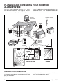
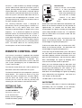
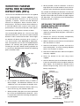
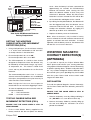
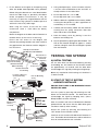
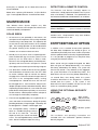
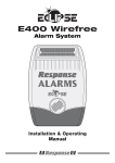
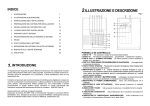
E100 Wirefree
Alarm System
Installation & Operating
Manual
FOREWORD
CONTENTS
Your decision to purchase an Eclipse Wirefree Solar
Alarm System represents a major and sensible step
towards total protection of your premises, its contents
and its occupants.
INTRODUCTION
The Eclipse Wirefree Solar Alarm System complies with
the requirements of BS6799 Class 1 for Wireless Alarms.
All components are designed and manufactured to
provide a high standard of security protection and long,
reliable service. In addition, the radio devices are tested
and approved by the Radio Regulatory division of the
Department of Trade and Industry (DTI) to ensure that
they will not interfere with other radio equipment. No
radio licence is required, however, the approved radio
frequency is not protected from interference and may be
withdrawn from use at any time subject to the DTI giving
users an appropriate notice period.
The Eclipse Wirefree Solar Alarm System is purposely
designed for installation by non-experienced people
using only conventional domestic tools. However, it is
essential that the lnstaller reads and fully understands
the advice and procedures contained in this manual
before proceeding with the installation. This manual
should be retained for future reference.
During installation, it is also important that the
procedures are followed in sequence.
IMPORTANT NOTE
All components, with the exception of the External
Solar Siren are only suitable for internal use.
SYSTEM SECURITY
This system has been designed to both detect intruders
and act as a strong deterrent to would-be intruders.
Please remember that given adequate knowledge and
time it is possible to overcome any alarm system and
we therefore recommend that an Intruder Alarm is used
in conjunction with good physical protection such as
security window and door locks.
The system is operated from one or more Remote
Control Units, which are encoded by the user to his/her
own House Code. The House Code can be changed at
any time by the user to suit the circumstances.
Page No.
1
PLANNING AND EXTENDING YOUR
WIREFREE SOLAR ALARM SYSTEM
2
WIREFREE EXTERNAL SOLAR SIREN
General Information
3
Location
3
Installation
3
Settings
4
Initial Power-up
Jamming Detection
4
4
REMOTE CONTROL UNIT
General Information
5
Setting up the Remote Control
5
WIREFREE PASSIVE INFRA RED MOVEMENT
DETECTORS (PIR’s)
Installation
6
Setting
7
Testing
7
OPTIONAL : WIREFREE MAGNETIC
CONTACT DETECTORS
Installation
7
TESTING THE SYSTEM
8
OPERATING INSTRUCTIONS
9
MAINTENANCE
10
ENTRY/EXIT DELAY OPTION
10
TROUBLE SHOOTING
11
EXTENDING YOUR SYSTEM
12
SPECIFICATION
Back Cover
Care should be taken to ensure that your Remote
Control Unit(s) are not lost as the finder could Disarm
your alarm before you are able to re-code the system.
Response
E100 Wirefree Alarm System
INTRODUCTION
The Eclipse Wirefree Solar Alarm System contains all
components necessary to install a complete system.
Wirefree items included are:
1 x Wirefree External Solar Siren
2 x PIR Movement Detectors
1 x Remote Control
2 x Wirefree Passive Infra Red
Movement Detectors (PIR’s)
Wirefree External Solar Siren
PANIC
ON
OFF
Wirefree
Remote Control
WP1.2-6
Rechargeable Battery
(Supplied fitted in the
Solar Siren)
Detector and Remote
Control Batteries
Also included:
Installation & Operating Manual
All necessary fixings
Window stickers
Eclipse E100
EXTENDING YOUR SYSTEM
Having selected a Wirefree Solar Alarm System, you
can increase your protection by adding additional
Wirefree Passive Infra Red Movement Detectors (PlR’s)
or Wirefree Magnetic Contact Detectors, either at the
time of initial installation or at a future date. You may
also wish to purchase additional Remote Control Units
for use by other members of your household or a
Wirefree Security Keypad to give a timed Entry/Exit
Delay. Full details of other accessories to extend your
system are given on page 12.
1
PLANNING AND EXTENDING YOUR WIREFREE
ALARM SYSTEM
For even greater protection you can fit as many
PlR Movement Detectors and Magnetic Contact
Detectors as and when you require. The Eclipse Alarm
System is designed to give you protection for a two
bedroomed house. Just add additional detectors
where further protection is needed.
External
Solar Siren
Magnetic Contact
Detector
PIR
PIR
Magnetic
Contact
Detector
SHED
Remote
Control
PIR
PIR
Back Door
KITCHEN
LOUNGE
DINNING
ROOM
HALL
GROUND FLOOR
GARAGE
PIR
PLANNING YOUR INSTALLATION
Before attempting to install your Wirefree Alarm System
it is important to study your security requirements and
plan your installation.
2
Each property will have its own layout, the diagrams
shown are intended only as a guide.
Eclipse E100
WIREFREE EXTERNAL SOLAR SIREN
GENERAL INFORMATION
HOUSING
The Siren and Solar Panel are all encapsulated within
a tough polycarbonate housing. This housing provides
full protection against adverse weather conditions. All
electronic components are specially treated to ensure
long, reliable, trouble free operation and an integral
tamper switch gives maximum security protection to
the unit.
SOLAR PANEL
The Solar Panel mounted on the housing will maintain
a charge to the rechargeable battery during daylight
hours. During darkness, a negligible amount of energy
is released by the rechargeable battery to operate the
Siren unit.
RECHARGEABLE BATTERY
A high capacity 6 Volt 1.2Ahr sealed lead acid
rechargeable battery ensures that the Siren is self
maintainable during darkness and long winter periods.
INITIAL POWER-UP BATTERY
An Alkaline 9 Volt PP3 battery is supplied in the
External Siren to boost the initial power to the unit.
HOUSE CODE
An encrypted code is set using a combination of
miniature switches. This enables you to select a
unique security code for your installation.
LOCATION
To provide the optimum amount of daylight to the
Solar Panel, you should ideally mount the Solar Siren
on a south facing wall. However, an easterly or
westerly position will suffice.
Although the Solar Siren is designed to work on any
aspect wall, for optimum performance you should
refrain from siting the unit on a north facing wall, where
possible.
Shadows cast by neighbouring walls, trees and roof
overhangs should also be avoided. In practice, the
Solar Siren should be positioned a minimum of twice
the width of the eaves overhang below the eaves.
Remember that in winter the sun is lower in the sky
and you should avoid winter shadows where possible.
Eclipse E100
NORTH
Avoid if
possible
EAST
WEST
SOUTH
Note: The Solar Panel does not have to be
mounted in direct sunlight, but does require a
minimum of two hours of daylight each day.
The External Solar Siren contains a sophisticated
radio receiver. However, reception of radio signals
can be affected by the presence of metallic objects
within the vicinity of the Solar Siren. It is therefore
important to mount the Solar Siren a minimum
distance of 1 metre radius away from any external
or internal metalwork, ie. external drainpipes, gutters
and internal radiators, mirrors etc.
It is recommended that you check the suitability of
your chosen location for the Solar Siren by temporarily
fitting it to the external wall. Power up the unit and
Remote Control, as described below, and check that
you can operate the Siren from in and around the
property, and from all locations where you plan to
install detectors.
INSTALLATION
Remove the holding screw from the base of
the housing and carefully hinge off the front cover.
All electronic components are housed within the
front cover.
Use the rear back-plate as a template to mark the
position of the four fixing holes on the external wall.
Drill four 6mm diameter holes and insert the plastic
wall plugs. Mount the back-plate using the four
screws provided.
3
Solar Panel
Front cover
locating tabs
Receiver
Aerial
7.5 Volt DC
charging adaptor
input
Dip switch
cover
Tamper
switch
Bleep Disable Link
P2
Siren Disable Link
P3
P1
J.D. Link
1
2
3
4
5
6
7
8
6 Volt 1.2Ahr
rechargeable
battery
9
ON
House Code
dip switches 1-8
9 Volt PP3 initial
power up battery
Printed circuit
board enclosure
Siren
Alarm duration
dip switch 9
Optional Strobe
Upgrade PCB
View of inside
Solar Siren
SETTINGS
INITIAL POWER-UP
Undo the 3 screws holding the dip switch cover in place
and remove the cover.
Alarm Duration
Connect the 9 Volt PP3 initial power battery to the clipon connectors. Connect the rechargeable battery to
the charging leads red to red (+) and black to black (-)
DIP switch 9
HOUSE CODE
Under the cover you will
find a series of miniature
dip switches.
ON
1
2
3
4
5
6
7
8
9
House Code
(Always change from the factory setting)
Select and record a random combination of ‘ON’ and
‘OFF’ positions for dip switches 1 - 8. This is your
House Code that enables all of your transmitters to
communicate with your Solar Siren.
Note: When the Solar Siren is viewed as shown above
(Solar panel at top) the dip switches are ‘upside down’.
ALARM DURATION
This is the length of time that the alarm will sound for,
following activation. Alarm duration can be set for either
1 or 3 minutes. Set dip switch 9 ‘OFF’ for 1 minute or ‘ON’
for 3 minutes. (If accidently triggered, the alarm can be
stopped at any time using the Remote Control).
BLEEP DISABLE
The Solar Siren will acknowledge signals from the
Remote Control by bleeping. It is possible to disable
the bleeps if required by removing the jumper P2 on
the circuit board.
Once you have completed setting your House Code,
alarm duration and, if required, bleep disable, refit the
dip switch cover securely.
Note: Once the batteries have been connected, the unit
will be operational and it is important that the solar
panel receives sufficient light to maintain the battery
charge. Also, the unit should not be repeatedly set into
alarm during installation/testing, as this could rapidly
drain the battery.
Hinge the front cover locating tabs over the top edge of the
back plate, push the base of the siren cover into place and
secure with the holding screw.
IMPORTANT: Ensure that the rear tamper switch is
closed when you fit the siren cover to the back-plate (eg.
listen for the switch to click). If the switch does not close
this will prevent the Solar Siren from operating correctly.
If necessary, remove the siren cover again and adjust the
screw on the back-plate tamper knob to ensure the
switch closes on assembly.
The fitting of your Solar Siren is now complete and the unit
is automatically in Service Mode.
In Service Mode the Solar Siren will not acknowledge any
signal from Detectors, Personal Attack Buttons, Tamper
Switches etc. Service Mode is controlled from the Remote
Control - refer to pages 5 and 9 for details.
JAMMING DETECTION
Your Wirefree Alarm conforms to the requirements of
BS6799 class 1 for Wire-Free Intruder Alarm Systems
and complies with the British Standards for Jamming
4
Eclipse E100
Detection. In order to detect any attempts to illegally
jam the radio channel used with your alarm system a
special jamming detection function is incorporated
into the Solar Siren. If this feature is selected, and the
radio channel is jammed continuously for 30 seconds,
when the system is armed, the Solar Siren will emit a
pre-alarm series of rapid bleeps for 5 seconds. If the
jamming continues for a further 10 seconds or more a
full alarm condition will occur.
The Jamming Detection circuit is designed to
permanently scan for jamming signals. However, it is
possible that it may detect other local radio
interference operating legally or illegally on the same
frequency. If it is planned to operate the jamming
detection feature we recommend that the system is
monitored for false jamming alarms for at least 2
weeks prior to leaving the Jamming Detect function on
permanently. To select the Jamming Detect feature
simply fit the jumper link across P1 on the Solar Siren
PCB. For further advice on the Jamming Detect
function please call our Technical Helpline.
REMOTE CONTROL UNIT
One Remote Control Unit is supplied in the standard
package. However additional Remote Control Units
can be purchased separately, if required. Any
number of Remote Control Units can be used with
your system, providing they are all coded with the
system ‘House Code’.
The Remote Control Unit(s) are used to operate the
Solar Siren and to Arm and Disarm the system.
The Remote Control Unit also incorporates a personal
attack button. This sounds the alarm at any time
whether the system is armed or not. Just press ‘PANIC’
and the alarm will sound. If this is activated by
mistake you can cancel the alarm by pressing and
releasing the ‘OFF’ button on the Remote Control.
Eclipse E100
ON
OFF
ON
1
2
3
4
5
6
7
8
Stand within view of the Solar Siren and hold the ‘ON’
button on the Remote Control to the ‘ON’ position for
approximately 10 seconds until the Solar Siren
acknowledges the signal by emitting one long bleep
(unless Bleep Disable has been set). This operation
takes the Solar Siren out of Service mode and into
Disarmed mode.
To Arm the Solar Siren, press and release the ‘ON’
button on the Remote Control. The Solar Siren will
acknowledge the signal by bleeping once.
To Disarm the Solar Siren, press and release the ‘OFF’
button on the Remote Control. The Solar Siren will
acknowledge the signal by bleeping twice.
To test the range of the Solar Siren, press and release
the ‘OFF’ button on the Remote Control from in and
around the property and from all locations where you
plan to install the detectors, and check that the Solar
Siren acknowledges the signals by bleeping twice
each time the Remote Control is operated.
When you have finished testing the Solar Siren and
Remote Control, turn the Solar Siren to Service mode
by pressing and holding the ‘OFF’ button on the
Remote Control for approximately 10 seconds. The
Solar Siren will acknowledge the signals by bleeping
twice, followed by one long bleep, after which the
‘OFF’ button can be released.
The Solar Siren is now in Service mode.
IMPORTANT
Ensure that the Solar Siren is in Service mode before
proceeding with the installation of the detectors,
otherwise a full alarm condition will be caused.
SETTING UP THE
REMOTE CONTROL
12 VOLT BATTERY
Remove the cover with
a coin and insert the
battery with the negative (-)
towards the battery spring.
PANIC
HOUSE CODE
Inside you will find a row of 8 dip
switches 1 - 8. This is your House
Code. Set these switches
to the same combination of
House
‘ON’ and ‘OFF’ as the dip
Code
switches in the Solar
Siren. Replace the battery
cover.
PANIC
ON
OFF
5
WIREFREE PASSIVE
INFRA RED MOVEMENT
DETECTORS (PlR’s)
Two Passive Infra Red Movement Detectors are supplied
in the standard package. However, additional Passive
Infra Red Movement Detectors can be purchased
separately, if required. Passive Infra Red Movement
Detectors are designed to detect movement within a
protected area. The detector element detects differences
in Infra Red radiation when a person moves within the
protected area. If movement is detected, a radio signal is
transmitted to the Solar Siren to activate the alarm.
The recommended position for a Passive Infra Red
Movement Detector is in the corner of a room mounted
between 2 and 2.5 metres from the floor. At this height,
the detector will detect movement up to 6 metres at
110° and 12 metres at 60° depending on adjustment.
Also, in this position, the 110°/60° fan-shaped detection
patterns can normally offer greater protection than
mounting on a flat wall. Before selecting a position for
a Passive Infra Red Movement Detector the following
points should be noted:
110° angle
4. Where possible, mount the detector so that the
logical path of an intruder would cut across the fan
patterns rather than directly towards the detector.
Any number of PIR Movement Detectors can be used
with your system, providing they are all coded with the
System House Code and are within the radio range of
the Solar Siren. To install and set the PIR Movement
Detector, proceed as follows.
INSTALLING THE WIREFREE
PASSIVE INFRA RED MOVEMENT
DETECTORS (PIR’s)
1. Remove the battery cover by inserting a coin
under the cover lip and twisting open. Remove the
fixings pack.
2. Remove the screw (in the battery compartment)
holding the wall bracket to the detector.
3. Slide the bracket up and remove the wall bracket
from the detector as shown.
4. Hold the wall bracket in position and mark the
two mounting holes. (If corner mounting, drill pilot
holes in the chamfers as shown).
5. Drill two 4mm diameter holes and insert the plastic
wall plugs supplied.
6. Screw the bracket to the wall using screws
supplied.
2-2.5m
60° angle
7. Offer the detector up to the wall bracket and locate
it into one of the bracket slots to angle the detector
down slightly. Fix the detector in position on the
bracket using the fixing screw at the rear of the
battery compartment.
TOP
Fixings for
Corner Mounting
Up to 6m at 110° and 12m at 60°
TOP
1. Do not position the detector facing a window or
direct sunlight. PIR Movement Detectors are not
suitable for use in conservatories or draughty areas.
UP = 2
pulse
detection
2. Do not position the detector directly above any
source of heat, eg. fire, radiators, boiler etc.
3. Where possible, keep pets out of areas protected
by Passive Infra Red Movement Detectors. If this
is not possible, alternative mounting arrangements
may be required.
6
Pulse Count
Detection
Switch on
Side
DOWN = 1
pulse
detection
Fixings for
Surface Mounting
Eclipse E100
Anti
Tamper
Switch
House Code
ON
1
2
3
ON
1
2
3
4
5
6
7
8
9
10
4
5
6
7
8
9
10
IMPORTANT
Switch 9
MUST BE "ON"
Switch 10
MUST BE "OFF"
Backplate Fixing
Screw
View inside PIR Movement Detector
Battery Compartment
SETTING THE WIREFREE
PASSIVE INFRA RED MOVEMENT
DETECTORS (PIR’s)
1. Using a ball-point pen, set the miniature switches
1 - 8 to the same combination of ‘ON’ and ‘OFF’
as the dip switches in the Solar Siren.
2. Ensure that dip switch 9 is set to ‘ON’.
Ensure that dip switch 10 is set to ‘OFF’ .
3. The PIR incorporates an anti-false alarm feature
designed to compensate where the detector may
be affected by environmental changes, eg. insects,
air temperature, etc. This feature is called ‘Pulse
Count’ and may be selected for One or Two Pulse
Detection.
The recommended pulse count is One. In cases of
extreme environmental problems or if unattributable
false alarms are experienced, it may be necessary to
select Two Pulse Count Detection.
Note: The higher the Pulse Count, the more paces an
intruder will have to move before triggering the alarm.
To select the required pulse count move the switch on
the side of the detector:
UP = Two Pulse Detection
DOWN = One Pulse Detection
TESTING PASSIVE INFRA RED
MOVEMENT DETECTORS (PIR’s)
ENSURE THAT THE SOLAR SIREN IS STILL IN
SERVICE MODE.
cover. After the battery has been connected for
approximately 40 seconds the PIR Movement
Detector will become active causing the LED
above the detector window to flash every time
movement is detected. Where Two Pulse Count
Detection has been selected the LED will be dim
on first detection and brighter on the second.
2. By walking into the protected area, the detector will
now be triggered each time the detector senses
movement and the LED will flash. If necessary
re-adjust the detection distance by angling the
detector up or down on its wall bracket.
3. Replace the battery cover on the detector.
Note: When the detector is fully installed ie. battery
cover is refitted; the unit will not detect movement for
approx. 40 seconds after each activation. In normal
operation, with the battery cover on, the detector LED
will not flash on movement detection.
WIREFREE MAGNETIC
CONTACT DETECTOR(S)
(OPTIONAL)
It is possible to expand your Eclipse Wirefree Solar
Alarm System and enhance your security protection
using optional Wirefree Magnetic Contact Detector(s)
to protect opening doors, windows and patio doors
etc. Any number of Magnetic Contact Detectors can
be used with your system, providing they are all coded
with the system House Code and are within radio
range of the Solar Siren.
INSTALLATION
To install the optional Magnetic Contact Detector(s),
set the House Code and fit the batteries, proceed as
follows.
ENSURE THAT THE SOLAR SIREN IS STILL IN
SERVICE MODE.
1. Remove the battery cover by sliding and lifting it
off. (DO NOT use a screw driver to lever off).
2. Remove the battery holder by carefully tilting up
the end and sliding the connectors off of the
printed circuit board.
1. Fit the 9 Volt Alkaline battery supplied to the
battery terminals but do not replace the battery
Eclipse E100
7
3. Fix the detector and magnet to the opening using
either the double sided tape OR screws provided.
4. Using a ball-point pen, set the miniature switches
1-8 to the same combination of ‘ON’ and ‘OFF’ as
the dip switches in the Solar Siren.
Before fixing the detector to a metal door/window
check the radio range as previously described.
Under exceptional circumstances it may be
necessary to space the magnet/detector off the
metal surface using a plastic or wooden spacer to
achieve the necessary radio range.
6. Slide the batteries supplied into the battery holder,
ensuring that the positive (+) side is uppermost on
each battery as it is installed.
When using the screws ensure that the small
countersunk screw is used within the battery
compartment.
7. Carefully refit the battery holder into the Detector
ensuring that the spring connectors slide onto
either side of the circuit board.
Mount the Magnet to the door and the Detector to
the door frame, (or vice versa, if necessary).
8. Refit the battery cover by placing it over the
batteries and sliding it on.
Ensure that the arrows on the Magnet and
Detector are pointing towards each other and that
the gap between the Detector and the Magnet is
less than 5mm.
9. Test the operation by opening the door/window. The
LED on the Detector will light for approx. 1 second
and then extinguish each time the Magnet is parted
from the Detector.
5. Ensure dip switch 9 is set to ‘ON’.
Ensure dip switch 10 is set to ‘OFF’.
Slide Open and Lift Off
Do Not Use A Screwdriver
Tilt and remove
battery holder
and insert
two batteries
Raised Head Screw,
Key-hole Slot Fixing
Battery
Connector
Double Sided Tape
OR Screw Fixing
Small Countersunk
Screw Fixing
Location of Key-hole
Screw (underside)
Hole for Mounting
Screw
11mm
8mm
2
3
4
5
6
Printed
Circuit Board
ON
1
2
3
4
5
6
7
8
9
8
9
10
(Ensure back
surfaces
are flush)
Anti-Tamper
Switch
10
Detector
Note: only required on initial testing or if the Siren is
in Service mode.
Arm the system by pressing and releasing the ‘ON’
button on the Remote Control. The Solar Siren will
acknowledge the signal by bleeping once, (unless
Bleep Disable has been selected).
After 40 seconds walk into a PIR Movement Detector
protected area and ensure that the Solar Siren goes
into Alarm mode (ie. Siren sounds).
Disarm the system by pressing and releasing the
‘OFF’ button on the Remote Control.
Alternative
Mounting
8
Set the Solar Siren into Disarmed mode by pressing
and holding the ‘ON’ button on the Remote Control
for approximately 10 seconds until the Solar Siren
acknowledges the signal by emitting one long bleep.
ENSURE THAT THERE IS NO MOVEMENT IN ANY
PROTECTED AREA.
IMPORTANT
Switch 9
MUST BE "ON"
Switch 10
MUST BE "OFF"
House Code
Magnet
7
A) INITIAL TESTING
B) START OF TEST IF SYSTEM
ALREADY INSTALLED
ON
1
TESTING THE SYSTEM
Continue to test the other PIR Movement Detectors in
turn. Remember that the detectors need to settle for at
least 40 seconds between each activation.
Eclipse E100
To test the optional Magnetic Contact Detectors, Arm
the system using the remote control. Open the
protected door/window and ensure that the Solar
Siren goes into Alarm Mode.
Disarm the system using the Remote Control.
Test each Magnetic Contact Detector by arming and
disarming the system and operating each detector in
turn. When you have completed testing leave the
Solar Siren in the Disarmed Mode.
You may test your system at any time. However, it is
recommended that the system is tested at regular
intervals not exceeding 3 months.
OPERATING INSTRUCTIONS
When leaving the premises, the system must be armed.
However, before doing so, check that all windows
are closed and locked, all protected doors are closed
and PIR Movement Detectors are not obstructed.
Ensure that pets are restricted to areas not protected by
Passive Infra Red Movement Detectors, or that suitable
precautions have been taken to allow for pets.
To Arm the system, press and release the ‘ON’ button on
the Remote Control, from outside the premises. Ensure
that the Solar Siren acknowledges the signal by bleeping
once. If you need to re-enter the premises, the system
must first be disarmed or a full alarm will occur.
To Disarm the system, press and release the ‘OFF’ button
on the Remote Control from outside the premises.
Ensure that the Solar Siren acknowledges the signal by
bleeping twice. Do not enter the protected premises until
the system has been disarmed or a full alarm will occur.
IMPORTANT
If, when you Disarm, the Solar Siren emits a series of TEN
rapid bleeps, this indicates that the system has been
triggered into alarm whilst it was armed. CHECK THE
SECURITY OF THE PROPERTY BEFORE ENTERING.
DISARMING AFTER AN INTRUSION
A full alarm condition will be initiated following any
intrusion. This condition will continue until expiry of the
pre-set alarm duration time (1 or 3 minutes) whereby the
siren will cease. The Solar Siren will now immediately
re-arm itself. In the event of a further intrusion the Solar
Siren will once again initiate a full alarm condition and
this process can be repeated up to three times. If a full
Eclipse E100
alarm condition is initiated accidently the alarm can be
stopped immediately by pressing and releasing the
‘OFF’ button on the Remote Control.
SYSTEM SERVICE MODE
To prevent the alarm from being activated when either
opening the Solar Siren or removing a battery cover from
a detector, it is necessary to first turn the Solar Siren to
Service mode by pressing and holding the ‘OFF’ button
on the remote control for approximately 10 seconds.
The Solar Siren will acknowledge the signal by bleeping
twice, followed by one long bleep after which the ‘OFF’
button can be released.
When you have completed your alterations to the system
turn the Solar Siren back to Disarmed Mode by pressing
and holding the ‘ON’ button on the remote control for
approximately 10 seconds until the Solar Siren
acknowledges the signal by emitting one long bleep.
PERSONAL ATTACK ALARM
A full alarm condition can be initiated by the user
at any time (system armed or disarmed) in the event of
threat or danger. To initiate a personal attack alarm press
and release the ‘PANIC’ Button on the Remote Control.
The Solar Siren will emit a full alarm sound which will
continue for the alarm duration time (1 or 3 minutes) or
until the system is reset by pressing and releasing the
‘OFF’ button on the Remote Control.
BATTERY MONITORING
The system will continuously monitor the battery
condition of all PIR Movement Detectors. If the voltage
level of any PIR battery falls below 7.5 Volts the red LED
on the detector will flash to let you know that the battery
needs to be replaced.
To identify PIR Movement Detector(s) with a low battery,
leave each protected area for a least 40 seconds. If,
when you re-enter the area, the detector LED flashes on
detection of movement, this indicates a low battery.
The batteries in the optional Magnetic Contact Detectors
can be checked by operating the detector (opening and
closing the protected door/window) and observing the
LED on the detector. If the LED is dim or does not
illuminate the batteries need to be replaced.
In the event of a detector low battery condition, turn the
Solar Siren to Service mode using the Remote Control
as previously described. When you have replaced the
9
battery(ies) as required turn the Solar Siren back to
Disarmed Mode.
Note: When replacing PIR batteries, fit PP3 Alkaline
type. Rechargeable batteries should NOT be fitted.
MAINTENANCE
Your Wirefree Alarm System requires very little
maintenance. However, a few simple tasks will ensure its
continued reliability and operation.
SOLAR SIREN
1. At least once a year, preferably in the Autumn, the
solar panel on the top of the siren housing should be
cleaned using a soft, damp cloth. This operation will
ensure that the solar panel receives all the available
light. The cleaning operation can be combined with
the general cleaning of the outside of the house,
windows etc. to reduce maintenance time.
2. Should you, for any reason, have to completely powerdown the Solar Siren (eg. to move the system to a new
premises) turn the Solar Siren to Service mode,
disconnect the rechargeable battery and initial powerup battery and ensure that the solar panel is covered
with a light proof material to prevent it being energised.
3. The Solar Siren should not be left for long periods
with the batteries connected, unless the unit is able
to receive sufficient light to maintain the battery
charging circuit. Failure to maintain charge to the unit
will result in the rechargeable battery running
unacceptably low. Should this occur, the unit must
be recharged from a 240/7.5 Volt DC 100mA mains
adaptor (Response order code Solar S100TR). When
re-powering the Solar Siren fit a new 9 Volt PP3 leak
proof Alkaline initial power-up battery to ensure that
the Unit receives sufficient power until the solar panel
can recharge the main battery completely.
4. The main rechargeable battery has a typical life of 3-4
years and needs no maintenance during this period,
providing the battery is kept charged. The battery will
be damaged if it is stored in a discharged state.
The rechargeable battery should be
taken to a suitable Recycling Centre at
the end of its useful life. DO NOT
dispose of with your normal household
Pb
waste. The rechargeable battery contains Sulphuric
Acid - DO NOT attempt to open the casing.
10
DETECTORS & REMOTE CONTROL
The Detectors and Remote Control(s) require no
maintenance. Simply replace the batteries once a year or
when a low battery is indicated. The specifications for
the Detector and Remote Control batteries are as follows:
PIR Movement Detectors:
Remote Controls:
9 Volt PP3 Alkaline
12 Volt 23A Alkaline
Optional Magnetic 2 x 3 Volt 230mAhr Lithium Cells
Contact Detectors:
(Panasonic CR2032 or equivalent)
Please recycle used batteries where Local Authority
facilities exist. Keep batteries away from children
and do not dispose of in fire.
ENTRY/EXIT DELAY OPTION
In addition to the standard Instant alarm operation;
the Solar Siren incorporates the facility to give a 15
second Entry/Exit Delay time when used in conjunction
with the optional Wireless Security Keypad CA2000KP.
It is not possible to programme an Entry/Exit Delay
using only the Remote Control.
When armed using the optional Keypad, the Solar
Siren will give one bleep followed by a 15 second
Exit Delay; followed by one bleep. The system will
then be fully armed. If any detector is then triggered,
the system will initiate a 15 second Entry Delay. The
Solar Siren will emit one long bleep followed by a
15 second Entry time during which the system
should be disarmed via the Keypad or a Remote
Control from the system. If the system is not
disarmed a full alarm condition will occur at the end
of the 15 second Entry Delay period.
USING THE OPTIONAL SECURITY
KEYPAD:-
?
?
?
?
ON
Arms system
with 15 second
Entry/Exit Delay
?
OFF
Disarms system
Access Code
?
?
?
Access Code
Full installation and operating instructions are
included with the CA2000KP optional Wirefree
Security Keypad.
Eclipse E100
TROUBLE SHOOTING
Symptom
/ Recommendation
Siren gives full alarm condition when arming
1. Rear anti-tamper switch on siren is open - ensure
that it is pressed fully closed. The wall is possibly
uneven, the siren may need relocating to a more
suitable position.
Symptom
/ Recommendation
PIR Movement Detector not detecting a
person’s movement
1. Ensure ‘House Codes’ are the same in the Solar Siren
and Remote Control.
2. Solar Siren in Service Mode. Turn to Disarmed Mode
using Remote Control (see ‘System Service Mode’
page 9).
3. Disconnect rechargeable and initial power-up batteries.
Cover Solar panel and leave unit for 1 minute.
Reconnect batteries remove Solar panel cover and
take out of Service Mode.
4. Solar Siren rechargeable battery discharged. Fit new
initial power-up battery and re-power up siren.
1. Check battery connections are good.
2. Pulse count set too high - reset to one pulse count
detection.
3. Ensure switches 9 and 10 in detector are set correctly.
4. Allow up to one minute for detector to settle down.
5. Ensure that detector is mounted the correct way
up (battery compartment at the bottom, except for
‘Pet Alley’).
6. Ensure that the detector is mounted at the correct
height (2 - 2.5m from floor, except ‘Pet Alley’).
7. Check that the detector is correctly set up.
(See setting the PIR Movement Detectors page 7).
8. If detector is mounted upside down for ‘Pet Alley’
check that the mounting height is not greater than 1m
from the floor, depending on size of pet.
Solar Siren gives full alarm condition when
system has not been activated by an intruder
Red LED on Remote Control not illuminating,
or is dim when unit is operated
1. Tamper switch activation - check all detector battery
covers for security and Solar Siren for adequate fixing
against external wall.
2. Personal Attack Alarm operated from Remote Control(s)
3. Jamming detection circuit operation (see page 4 for advice)
1. Ensure battery is connected with correct polarity.
2. Ensure battery connections are good.
3. Replace battery with Alkaline type.
Solar Siren not responding to detectors
1. Check batteries by observing detector LED.
2. Ensure ‘House Code’ is the same as Solar Siren.
3. Ensure dip switches 9 and 10 are set correctly.
Solar Siren not re-acting to Remote Control(s)
1. Ensure that the ‘House Code’ on the detector is the
same as the Solar Siren.
2. Ensure detectors are within radio range of Solar Siren
and equipment is not close to metal objects.
3. Replace detector battery(ies).
PIR Movement Detector false alarming
1. Ensure that the detector is not pointing at a source of
heat or a moving object.
2. Ensure that the detector is not mounted above a
radiator or heater.
3. Ensure that the detector is not facing a window or in
direct sunlight.
4. Ensure that the detector is not in a draughty area.
PIR Movement Detector LED flashes on
detection of movement, with battery cover on
Optional Magnetic Contact Detector not working
Red LED on Magnetic Contact Detector not
illuminating or is dim when door or window
is opened
1. Ensure batteries are connected with correct polarity.
2. Ensure battery connections are good.
3. Replace batteries.
Magnetic Contact Detector false alarming
1. Ensure that gap between magnet and detector is less
than 5mm.
2. Tamper switch below battery cover not depressed.
Check battery cover fixing lugs are not broken.
1. Low battery - replace Alkaline battery.
HELPLINE
If you need help, just dial for
expert technical support
Important
notice
following
alarm
installation
Eclipse E100
01372 450960
(Lines open 9.00am to 6.00pm, Monday to Friday).
In order to comply with the Code of Practice on Noise from Intruder Alarms 1981 you should carry out the
following procedures within 48 hours of Intruder Alarm installation.
1. Notify your local police station in writing that an Intruder Alarm System has been installed, giving names and
contact details of at least two persons who have access to a Remote Control.
2 Inform the Local Environmental Health Authority of the installation and which police station has been informed.
3 Ensure that all users are aware of the operating procedures.
4 Immediately inform your Local Authority and police station if there is a change to the persons who have
Remote Controls.
11
EXTENDING YOUR E100 WIREFREE ALARM SYSTEM
You may add Wirefree Magnetic Contact Detectors and additional Wirefree PIR Detectors etc. from the CA2000
range of accessories as required, to give additional protection where needed. The following accessories are also
available to extend and enhance your system.
ACCESSORIES
STROBE UPGRADE
CA2000STR
STROBE UPGRADE
(This part only)
Add to your existing Siren Unit to give full Siren & Strobe protection.
The Strobe Flash Light is activated simultaneously with your siren
which will help identify a house in alarm condition.
CA2000STR
DUMMY SIREN E100D
The Siren is available as a dummy design and acts as an excellent
visual deterrent.
WIREFREE MAGNETIC CONTACT DETECTOR
CA2000M
E100D
Protect opening doors and windows using this slimline Wirefree
Magnetic Contact Detector. Simple to install on most doors and
windows using the double sided adhesive pads or screws supplied.
The detector senses when the magnet moves away from the side of
the detector and sends a coded radio signal to the Solar Siren to
initiate an alarm.
Supplied complete with 2 x 3 Volt Lithium batteries.
CA2000M
WIREFREE SECURITY KEYPAD CA2000KP
This small battery operated keypad requires no wiring and is fitted in
minutes. It sends security coded radio signals to your Siren and only
allows access to those who know your user changeable access code.
1
2
3
4
ON
OFF
CA2000KP
12
Designed for installation inside the property the Keypad allows you
to set a 15 second Entry/Exit Delay on your system for greater
flexibility. The ideal location for the Keypad is normally adjacent to
the main entrance door for easy access when entering or leaving the
premises. Supplied complete with 9 Volt alkaline battery.
Eclipse E100
If you need help, just dial the Helpline
for expert technical support:
01372 450960
(Lines open 9.00am to 6.00pm, Monday to Friday).
We can solve most problems quickly over the phone.
GUARANTEE
This product (excluding Alkaline batteries) is guaranteed for one year from
the date of purchase against faulty materials or workmanship. We will
repair or replace any faulty product. No liability can be accepted for any
problems caused by fair wear and tear, buyers negligence, improper
fitting or use, local radio interference, wilful or accidental damage, or any
consequential loss or damage howsoever caused. This guarantee does
not affect your statutory rights and is valid in the UK and Eire only.
If an item develops a fault, please call the Helpline on the above number.
Should you need to return a product, it must be to the address below in
adequate packaging with:
1. A copy of your original invoice/receipt.
2. A full description of the fault.
3. All relevant batteries.
NOTE:
If returning a system, make sure that all batteries are disconnected and
secure and that the unit is adequately packaged to prevent damage in transit.
For security, Recorded or Registered Post is recommended.
17 Church Road, Great Bookham, Surrey KT23 3PG
Telephone: 01372 450960
E-mail: [email protected]
www.wireless-alarms.net
E100 Wirefree Alarm System
Response
ECLIPSE E100 SPECIFICATION
External Solar Siren
Wirefree
Remote Control
315
mm
1
2
3
4
ON
OFF
98
mm
70
25
mm
225
mm
85
mm
● Case material 3mm Polycarbonate
● Dual front and rear anti-tamper
● Internal receiver and aerial UK
●
●
●
●
●
●
●
●
●
●
●
●
RESEARCH &
DEVELOPMENT
Our R & D Department is constantly
developing new products.
We practice a policy of continued
improvement and reserve the right
to change specifications
without prior notice.
●
●
frequency 418MHz
Sealed lead acid battery 6 Volt 1.2Ahr
Solar Panel 7.5 Volt - Charge Rate
typically 60mA
Time out - switchable
Audible confirmation - selectable
Auto confirmation on set up
High Power Piezo Siren
Siren prohibit - selectable
System range up to 100m in free air space
Operation time in complete
darkness - 40 days
Auto reset on activation
Jamming Detection
Anti-foam
15 second Entry/Exit Delay facility when
operated via Optional Wirefree Security
Keypad CA2000KP
Optional Strobe Upgrade CA2000STR
● User changeable four digit access code
● On-Air indicator
● 15 second Entry/Exit Delay facility
● Anti-tamper
● Indoor use only
● Dual Personal Attack buttons
● Low battery indicator
● Alkaline battery supplied
Wirefree
Security Keypad
(Optional)
52
mm
125
mm
12
10
mm
mm
26
15
mm
Wirefree Passive Infra
Red Movement Detector
mm
● LED battery confirmation
● Anti-tamper
● Operating gap 5mm
● Door or window mounting
● Lithium batteries supplied
Wirefree Magnetic
Contact Detector
141
If you need help,
just dial the
Helpline for expert
technical support
mm
mm
(Optional)
PANIC
62
mm
45
mm
ON
OFF
78
mm
● Detection range: up to 6 metres at 110°
and 12 metres at 60°
HELPLINE:
01372 450960
(Lines open 9.00am to 6.00pm,
Monday to Friday.
0359
RADIO DEVICES FOR
USE IN THE UK
WA_08/04
● Walk test facility
● One or two pulse count detection
● RF immunity
36
mm
17
mm
● Low battery indicator
● Anti-tamper
● Instant ON/OFF
● Adjustable wall bracket
● Personal attack button
● Corner or surface mount
● LED confirmation
● Pet mount option
● Alkaline battery supplied
● Alkaline battery supplied
● No Entry/Exit Delay facility
Wireless Alarms. 17 Church Road, Great Bookham, Surrey KT23 3PG
Telephone: 01372 450960 E-mail: [email protected] www.wireless-alarms.net
E100