1
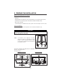
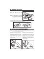
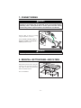
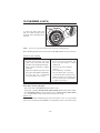
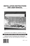
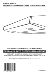
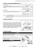
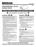
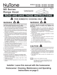
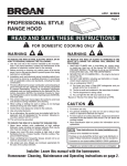
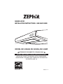
RANGE HOOD
INSTALLATION INSTRUCTIONS - USE AND CARE
HB0064
MODEL ES1-E30AB, ES1-E30AS, ES1-30AW
! INTENDED FOR DOMESTIC COOKING ONLY !
READ AND SAVE THESE INSTRUCTIONS
INSTALLER: LEAVE THIS MANUAL WITH HOMEOWNER.
HOMEOWNER: CLEANING AND OPERATION INFORMATION
ON PAGES 9 AND 10.
DEC07.0101
06683 rev. A
9
!
WARNING
TO REDUCE THE RISK OF FIRE,
ELECTRIC SHOCK OR INJURY TO
PERSONS, OBSERVE THE FOLLOWING:
1. Use this unit only in the manner intended
by the manufacturer. If you have questions,
contact the manufacturer at the address
or telephone number listed in the warranty.
2. Before servicing or cleaning unit, switch
power off at service panel and lock service
disconnecting means to prevent power
from being switched on accidentally.
When the service disconnecting means
cannot be locked, securely fasten a
prominent warning device, such as a
tag, to the service panel.
3. Installation work and electrical wiring
must be done by qualified personnel in
accordance with all applicable codes
and standards, including fire-rated
construction codes and standards.
4. Sufficient air is needed for proper
combustion and exhausting of gases
through the flue (chimney) of fuel burning
equipment to prevent backdrafting.
Follow the heating equipment manufacturer’s
guidelines and safety standards such as
those published by the National Fire
Protection Association (NFPA), and the
American Society for Heating, Refrigeration
and Air Conditioning Engineers (ASHRAE),
and the local code authorities.
5. When cutting or drilling into wall or ceiling,
do not damage electrical wiring and
other hidden utilities.
6. Ducted fans must always be vented to
the outdoors.
7. Do not use this unit with any solid-state
speed control device.
8. To reduce the risk of fire, use only metal
ductwork.
9. This unit must be grounded.
TO REDUCE THE RISK OF A RANGE TOP
GREASE FIRE:
a) Never leave surface units unattended at
high settings. Boilovers cause smoking
and greasy spillovers that may ignite.
Heat oils slowly on low or medium settings.
b) Always turn hood ON when cooking at
high heat or when cooking flambeing
foods (e.g.: crêpes Suzette, cherries
jubilee, peppercorn beef flambé).
c) Clean ventilating fans frequently. Grease
should not be allowed to accumulate on
fan or filter.
d) Use proper pan size. Always use cookware
appropriate for the size of the surface
element.
-
!
WARNING
TO REDUCE THE RISK OF INJURY TO
PERSONS IN THE EVENT OF A RANGE TOP
GREASE FIRE, OBSERVETHE FOLLOWING*:
1. SMOTHER FLAMES with a close-fitting
lid, cookie sheet or metal tray, then turn
off the burner. BE CAREFUL TO
PREVENT BURNS. IF THE FLAMES DO
NOT GO OUT IMMEDIATELY, EVACUATE
AND CALL THE FIRE DEPARTMENT.
2. NEVER PICK UP A FLAMING PAN –
You may be burned.
3. DO NOT USE WATER, including wet
dishcloths or towels – This could cause
a violent steam explosion.
4. Use an extinguisher ONLY if:
A.You own a Class ABC extinguisher
and you know how to operate it.
B.The fire is small and contained in the
area where it started.
C.The fire department has been called.
D.You can fight the fire with your back to an exit.
*Based on “Kitchen Fire Safety Tips
published by NFPA.
CAUTION
1. For general ventilating use only. Do not
use to exhaust hazardous or explosive
materials and vapors.
2. To avoid motor bearing damage and noisy
and/or unbalanced impeller, keep drywall
spray, construction dust, etc. off power unit.
3. Your hood motor has a thermal overload
which will automatically shut off the
motor if it becomes overheated. The
motor will restart when it will cool down.
If the motor continues to shut off and
restart, have thehood serviced.
4. The minimum hood distance above
cooktop must not be less than 20” for an
electric range, and 24” for a gas range.
A maximum of 30” above cooktop is
highly recommended for best capture of
cooking impurities.
5. Two installers are recommended because
of the large size and weight of this hood.
6. To reduce the risk of fire and to properly
exhaustair, be sure to duct air outside – Do
not exhaust air into spaces within walls or
ceiling or into attics, crawl space or garage.
7. Because of the high exhausting capacity of
this hood, you should make sure enough air is
entering the house to replace exhausted air by
opening a window close to or in the kitchen.
8. Use with approved cord-connection kit only.
9. Please read specification label on product
2 - for further information and requirements.
ABOUT THIS MANUAL
Please take note this manual uses the following symbols to emphasize particular information:
! WARNING
Identifies an instruction which, if not followed, might cause serious
personal injuries including possibility of death.
CAUTION
Denotes an instruction which, if not followed, may severely damage the unit
and/or its components.
NOTE: Indicates supplementary information needed to fully complete an instruction.
TOOLS NEEDED TO INSTALL THE RANGE HOOD
- Phillips screwdriver no. 2 or Robertson no. 1 and no. 2
- Hammer and flat blade screwdriver (to open the knockout holes)
- Sheet metal sheers
- Pair of pliers
- Scissors (to cut duct tape)
- Pen
- Wire stripper
TABLE OF CONTENTS
1. INSTALL DUCTWORK . . . . . . . . . . . . . . . . . . . . . . . . . . . . . . . . . . . . . . . . . . . . . . . . 4
2. MEASURE THE INSTALLATION . . . . . . . . . . . . . . . . . . . . . . . . . . . . . . . . . . . . . . . . . . 4
3. PREPARE THE INSTALLATION . . . . . . . . . . . . . . . . . . . . . . . . . . . . . . . . . . . . . . . . . . . 5
4. PREPARE THE HOOD . . . . . . . . . . . . . . . . . . . . . . . . . . . . . . . . . . . . . . . . . . . . . . . . 6
5. INSTALL THE ADAPTER/DAMPER . . . . . . . . . . . . . . . . . . . . . . . . . . . . . . . . . . . . . . 6-7
6. INSTALL THE HOOD . . . . . . . . . . . . . . . . . . . . . . . . . . . . . . . . . . . . . . . . . . . . . . . . . 7
7. CONNECT WIRING . . . . . . . . . . . . . . . . . . . . . . . . . . . . . . . . . . . . . . . . . . . . . . . . . 8
8. REINSTALL BOTTOM PANEL
AND
FILTERS . . . . . . . . . . . . . . . . . . . . . . . . . . . . . . . . . . 8
9. FLUORESCENT LAMPS . . . . . . . . . . . . . . . . . . . . . . . . . . . . . . . . . . . . . . . . . . . . . . . 9
10. CLEANING . . . . . . . . . . . . . . . . . . . . . . . . . . . . . . . . . . . . . . . . . . . . . . . . . . . .9-10
11. OPERATION . . . . . . . . . . . . . . . . . . . . . . . . . . . . . . . . . . . . . . . . . . . . . . . . . . . . 11
12. REPLACEMENT PARTS . . . . . . . . . . . . . . . . . . . . . . . . . . . . . . . . . . . . . . . . . . . . . 11
-3-
1. INSTALL DUCTWORK
Plan where and how the ductwork will be installed.
Install proper-sized ductwork, elbow(s) and roof or wall cap for the type of blower you are
installing. If using 6’’ (150 mm) round ducts, use a transition. Use 2’’ (50 mm) duct tape to
seal duct joints.
Roof cap
Roof cap
6” round duct
3¼” x 10” duct
3¼” x 10” to 6”
round transition
Wall cap
Wall cap
Hood
Hood
HH0014A
HH0011A
2. MEASURE THE INSTALLATION
Dimensions for the most common installations are shown below.
We recommend to install the hood at a minimum of 20” (508 mm) from an electric
range and at 24” (610 mm) from a gas range.
For optimal performance, the hood should not be installed more than 30” (762 mm) from
cooktop.
Cabinets
Cabinets
Hood
Hood
30” maximum
clearance
20” minimum
clearance
(24” for gas)
Standard
36” height
cooktop
Standard
36” height
cooktop
HH0012A
HH0013A
-4-
3. PREPARE THE INSTALLATION
Make sure the following items are included:
- Hood
- Filters (2)
- Adapter/damper assembly 3¼’’ x 10’’ (located inside the hood, under the bottom panel)
- Compact fluorescent lamps (120 V, 13 W, PLC13, 2700 K with G24q-1 base)
- Bag of parts including:
(1) wire clamp, (5) 1/2’’ double thread screws, (2) wire connectors and (6) no. 6 x 1/2’’ screws
Parts sold separately:
- Transition 3¼”x 10” to 6” round (optional, for 6” round ducts installation only)
CAUTION
When performing installation, servicing or cleaning the unit, it is recommended
to wear safety glasses and gloves.
NOTE:
If the bottom of the cupboard is recessed,
attach wood strips (not included), as shown
beside, in order to properly install the range
hood under the cabinet. The wood strips must
be as thick as recess.
23 8 ”
HO0002A
Cut-out the openings for duct (A) and power cable (B), in cabinet or wall, according to the
direction of discharge chosen.
See figures below.
HORIZONTAL DISCHARGE:
VERTICAL DISCHARGE:
CABINET BOTTOM
C
L
C
L
A
111 8 ”
10½”
1¼”
3¾”
1½”
A
3½”
HD0150A
7
8”
5¼”
HD0151A
B
5¼” 5¼”
1¼” dia.
-5-
¾”
5¼”
3 8”
B
4. PREPARE THE HOOD
A
Remove both filters from the hood.
Disassemble the adaptor/damper (A) from the
hood.
NOTE: The adapter/damper is located inside
the hood. Remove the bottom panel
(B) to access the adapter/damper.
Refer to figure beside.
B
HO0093
Punch out the electrical and discharge knock-outs for the chosen opening (vertical on top or
horizontal at the back of the hood). Refer to figure below.
VERTICAL DISCHARGE
HORIZONTAL DISCHARGE
HD0219
5. INSTALL THE ADAPTER/DAMPER
NOTE: If this hood replaces another one, please note that the location of the air exhaust
can vary from one manufacturer to another.
HORIZONTAL
DISCHARGE, NEW INSTALLATION
HORIZONTAL
Fold down the foldable flange (C) of the
adapter/damper. This flange must be at 90°
from the remaining flanges. Use the lower
screw holes on each side of the
adapter/damper to assemble it to the back
of hood. See below.
DISCHARGE, HOOD REPLACEMENT
It may be necessary to adjust the
adapter/damper location to the existing wall
discharge opening. Leave the foldable
flange (C) of the adapter/damper as is. Use
the upper screw holes on each side of the
adapter/damper to assemble it to the back
of hood. See below.
C
C
HJ0008
HJ0009
-6-
5. INSTALL THE ADAPTER/DAMPER (CONT’D)
VERTICAL
DISCHARGE
For a vertical discharge installation only,
leave the foldable flange (C) of the
adapter/damper as is. This flange must be
located towards the front of the hood.
See beside.
C
HO0096
ALL
INSTALLATIONS
Using two 1/2” screws, secure the
adapter/damper to the top or back of the
hood. Tape the adapter/damper to the hood
using duct tape to seal it.
HO0095
NOTES:
1. For the best ventilation performance, if a round duct must be used, the duct
diameter must be 6” or more. Use a 3¼” x 10” to 6” round transition.
2. The wall duct must be well prepared to receive the adapter. Before performing
the installation, make sure the adapter fits easily in the duct.
6. INSTALL THE HOOD
Run power cable to installation
location. Place the hood at its
location. Using a pen, mark the
position of the screws (smaller part
of the embossed keyholes).
Remove the hood and install four
1/2” double thread screws at sides
locations (A), leaving a 1/8” gap.
Place the wire clamp, insert the
cable in the hood and tighten the
wire clamp to secure the cable.
Place the hood under the cabinet
and slide it in position. Make sure
the adapter/damper assembly
enters the ducting and the damper
opens freely. Secure the hood by
tightening the screws completely.
Install the last 1/2 double thread
screw (B) in the remaining
embossed hole.
HD0218
-7-
7. CONNECT WIRING
! WARNING
Risk of electrical shock. Electrical wiring must be done by qualified
personnel in accordance with all applicable codes and standards. Before
connecting wires, switch power off at service panel and lock service
disconnecting means to prevent power to be switched on accidentally.
Connect cable to range hood wiring
using included wire connectors.
1
Connect BLACK to BLACK, WHITE to
WHITE and GREEN or BARE WIRE to
GREEN ground screw (1).
HE0059
! WARNING
Do not forget to connect the ground!
8. REINSTALL BOTTOM PANEL AND FILTERS
Reinstall the bottom panel, using the
retaining screw previously removed in
step 4 plus 4 others from parts bag.
Refer to illustration beside.
Then, reinstall filters.
HO0097
-8-
9. FLUORESCENT LAMPS
! WARNING
This product contains fluorescent lamps containing mercury. Dispose of
appropriately, according to local laws and requirements.
This range hood must use compact fluorescent lamps (120 V, 13 W, PLC13, 2700 K with
G24q-1 base) (included).
! WARNING
In order to prevent the risk of personal injury, the fluorescent tubes must be
cooled down before removing them.
NOTE: The range hood is shipped with both fluorescent lamps packed behind the light diffuser.
1. To access fluorescent lamps, remove the light diffuser by pushing on its both tabs and
pulling it down.
2. To install the fluorescent lamps, slide their 4 prongs into their corresponding holes in their
socket until secured. Reinstall the light diffuser.
2
1
HO0098
To remove fluorescent lamps, remove the light diffuser and pull fluorescent lamps out of
their socket.
NOTE:
Some fluorescent lamps may produce a yellowish lighting on first usages. This
temporary effect will disappear by itself.
10. CLEANING
The grease filters, bottom panel,
intake ring (A) and blower wheel (B)
should be cleaned frequently. Use a
warm detergent solution. The grease
filters, intake ring and blower wheel
are dishwasher safe.
B
A
HD0220
NOTE:
Some minerals, when in contact with dishwasher soap additives, may cause filters
discoloration. This discoloration is not covered by the warranty.
-9-
10. CLEANING (CONT’D)
D
C
To remove the blower wheel, first
take off its intake ring. Then remove
the blower wheel by pulling it down
smoothly.
HD0156
NOTE:
Do not try to remove the black part (C) attached to the bottompanel.
When reinstalling the blower wheel, make sure the small tab (D) will fit into one hole of the motor.
STAINLESS
STEEL CLEANING:
Do:
Don’t:
•
• Do not use any steel or stainless steel
wool or any other scrapers to remove
stubborn dirt.
Regularly wash surfaces with clean
cloth or rag soaked with warm water
and mild soap or liquid dish detergent.
• Always clean in the direction of original
polish lines.
• Always rinse well with clear water (2 or 3
times) after cleaning. Wipe completely dry.
• You may also use a specialized
household stainless steel cleaner.
• Do not use any harsh or abrasive
cleansers.
• Do not allow dirt to accumulate.
•
Do not let plaster dust or any other
construction residues reach the hood.
During construction or renovation,cover
the hood to make sure no dust adheres
to stainless steel surface.
Avoid: when choosing a detergent
- Any cleaners that contain bleach will attack stainless steel.
- Any products containing: chloride, fluoride, iodide, bromide will deteriorate surfaces rapidly.
- Any combustible products used for cleaning such as acetone, alcohol, ether, benzol,
etc., are highly explosive and should never be used close to a range.
ENAMEL
FINISH:
Clean with warm water and mild detergent only. If discoloration occurs, use a good enamel
polish such as automotive polish. (DO NOT use rough abrasive cleaner or porcelain cleaner.)
- 10 -
11. OPERATION
Always turn on the hood before begining cooking in order to establish an air flow in the
kitchen. Let the blower run for a few minutes to clear the air after turning off the range.
MECHANICAL PUSH-BUTTON CONTROL
HC0021
A
B
C
A. OFF BLOWER SWITCH:
Press on this switch to stop the blower operation.
B. SPEED BLOWER SWITCHES:
Press on left switch (1) to turn on the blower on low speed, on middle switch
(2) to turn on the blower on medium speed, and on right switch (3) to turn on the
blower on high speed.
C ON/OFF LIGHTING SWITCH:
Press on this switch to turn on the fluorescent lights, and press again to turn
them off.
12. REPLACEMENT PARTS
Part no. (each)
Description
Z0B0024
50200026
Fluorescent Bulb, 13W G24
Metal Mesh Filter
Qty per Hood
- 11 -
2
2
www.zephyronline.com
Warranty
www.zephyronline.com
TO OBTAIN SERVICE UNDER WARRANTY
or any Service Related Questions, please call:
1-888-880-8368
Staple your receipt here.
Proof of the original purchase
date is needed to obtain service
under the warranty.
TO OBTAIN SERVICE UNDER WARRANTY: You must present proof of original purchase date.
Please keep a copy of your dated proof of purchase (sales slip) in order to obtain service under warranty.
One Year Service Repair Warranty:
For one year from date of original purchase, we will provide free of charge, service labor to repair any failed parts or
components due to manufacturing defects.
One Year Parts Warranty:
For one year from date of original purchase, we will provide free of charge, nonconsumable replacement parts or
components that failed due to manufacturing defects. Consumable parts not covered by this warranty include: Light Bulbs,
Metal and Charcoal Filters.
Who is Covered:
This warranty is extended to the original purchaser for products purchased for ordinary home use in the 48 mainland states,
Hawaii and Washington D.C. In Canada and Alaska, this warranty is Limited.
There might be costs associated with
shipping the products to our designated service locations or you might need to pay service technician's travel costs, to have
the appliance repaired in-home.
This Warranty will be Voided when:
Product damaged through negligence, misuse, abuse, accident. Improper installation and failure to follow installation instructions. When product is used commercially or other than its intended purpose. Damaged because of improper connection with
equipment of other manufacturers. Repaired or modified by anyone other than Zephyr's Authorized Agents.
What is Not Covered:
Consumable parts such as light bulbs, filters, and fuses. Services outside of service area and the labor cost incurred in
connection with the removal, shipping and reinstallation cost, nor does it cover any other contingent expenses. The natural
wear of finish, and wear due to improper maintenance, use of corrosive and abrasive cleaning products, pads, and oven
cleaner products. Chips, dents or cracks due to abuse, misuse, freight damage, or improper installation. Service trips to your
home to teach you how to use the product. Damage of product caused by accident, fire, floods or act of God.
This warranty is valid in the United States and Canada. It is non-transferable and applies only to the original purchaser and
does not extend to subsequent owners of this product. Any applicable implied waranties, including the warranty of
merchantability, are limited in duration to a period of express warranty as provided herein beginning with the date of original
purchase at retail and, no warranties, whether express or implied, shall apply to this product thereafter.
Have your product proof of purchase with date ready for warranty issues.
Or write to:
Zephyr Corporation
Service and Warranty Department
395 Mendell Street
San Francisco, CA 94124
JAN07.0101