1
CITY MULTI Control System
and Mitsubishi Mr. Slim Air Conditioners
MA Remote Controller
PAR-31MAA
Simple Operation Manual
Prior to use, thoroughly read the instructions in this manual to use the product correctly.
Retain for future reference.
Make sure that this manual, CD-ROM, and the Installation Manual are passed on to any
future users.
To ensure safety and proper operation of the remote controller, the remote controller should
only be installed by qualified personnel.
Safety precautions
• Thoroughly read the following safety precautions before using the unit.
• Observe these precautions carefully to ensure safety.
WARNING
CAUTION
Indicates a risk of death or serious injury.
Indicates a risk of serious injury or structural damage.
• After reading this manual, pass it on to the end user to retain for future reference.
• Keep this manual for future reference and refer to it as necessary. This manual should be made available
to those who repair or relocate the controller. Make sure that the manual is passed on to any future
users.
• For information not contained in this booklet, please refer to the Instruction Book on the CD-ROM that is
supplied with the Remote Controller.
General precautions
WARNING
Do not install the unit in a place where large
amounts of oil, steam, organic solvents, or corrosive
gases, such as sulfuric gas, are present or where
acidic/alkaline solutions or sprays are used
frequently. These substances can compromise
the performance of the unit or cause certain
components of the unit to corrode, which can result
in electric shock, malfunctions, smoke, or fire.
To reduce the risk of injury or electric shock, before
spraying a chemical around the controller, stop the
operation and cover the controller.
To reduce the risk of injury or electric shock, stop
the operation and switch off the power supply before
cleaning, maintaining, or inspecting the controller.
To reduce the risk of shorting, current leakage,
electric shock, malfunctions, smoke, or fire, do not
wash the controller with water or any other liquid.
If any abnormality (e.g., burning smell) is noticed,
stop the operation, turn off the power switch, and
consult your dealer. Continued use of the product
may result in electric shock, malfunctions, or fire.
To reduce the risk of electric shock, malfunctions,
smoke or fire, do not operate the switches/buttons or
touch other electrical parts with wet hands.
Properly install all required covers to keep moisture
and dust out of the controller. Dust accumulation and
water can cause electric shock, smoke, or fire.
When disinfecting the unit using alcohol, ventilate
the room adequately. The fumes of the alcohol
around the unit may cause a fire or explosion when
the unit is turned on.
2
CAUTION
To reduce the risk of fire or explosion, do not place
flammable materials or use flammable sprays
around the controller.
To reduce the risk of injury and electric shock, avoid
contact with sharp edges of certain parts.
To reduce the risk of damage to the controller, do not
directly spray insecticide or other flammable sprays
on the controller.
To avoid injury from broken glass, do not apply
excessive force on the glass parts.
To reduce the risk of environmental pollution, consult
an authorized agency for proper disposal of remote
controller.
To reduce the risk of injury, wear protective gear
when working on the controller.
To reduce the risk of electric shock or malfunctions,
do not touch the touch panel, switches, or buttons
with a pointy or sharp object.
Precautions for moving or repairing the controller
WARNING
The controller should be repaired or moved only by
qualified personnel. Do not disassemble or modify
the controller.
Improper installation or repair may cause injury,
electric shock, or fire.
CAUTION
To reduce the risk of shorting, electric shock, fire,
or malfunction, do not touch the circuit board with
tools or with your hands, and do not allow dust to
accumulate on the circuit board.
Additional precautions
To avoid damage to the controller, use appropriate
tools to install, inspect, or repair the controller.
This controller is designed for exclusive use with the
Building Management System by Mitsubishi Electric.
The use of this controller for with other systems or
for other purposes may cause malfunctions.
To avoid discoloration, do not use benzene, thinner,
or chemical rag to clean the controller. To clean the
controller, wipe with a soft cloth soaked in water with
mild detergent, wipe off the detergent with a wet
cloth, and wipe off water with a dry cloth.
To avoid damage to the controller, provide protection
against static electricity.
3
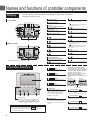
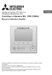
Names and functions of controller components
The main display can be displayed in two different modes: "Full" and "Basic."
The factory setting is "Full."
Display
Full mode
6
Room
Cool
Auto
1
3
i
3Clock
(See the Installation Manual.)
j
4Fan speed
4
a
Mode
Temp.
Fan
Fri
Cool
Set temp.
Auto
3
Appears while the units are operated in the
energy-save mode.
Functions of the corresponding buttons appear
here.
f
8
Appears when the preset temperature is centrally
controlled.
9
4
Appears when the Weekly timer is enabled.
e
Appears when the operation mode is centrally
controlled.
2
d
5Button function guide
7
Basic mode
appears when the timer is disabled by the
centralized control system.
Fan speed setting appears here.
Appears when the ON/OFF operation is centrally
controlled.
5
1
Current time appears here.
6
2
k
Appears when the On/Off timer, Night setback, or
Auto-off timer function is enabled.
Preset temperature appears here.
Fri
Set temp.
c
Indoor unit operation mode appears here.
2Preset temperature
b cd e f g h
7
8
9
0
1Operation mode
Appears when the filter reset function is centrally
controlled.
0
Appears while the outdoor units are operated in
the silent mode.
g
Appears when the built-in thermistor on the
remote controller is activated to monitor the
room temperature (a).
appears when the thermistor on the
indoor unit is activated to monitor the room
temperature.
h
Indicates the vane setting.
i
Indicates the louver setting.
Indicates when filter needs maintenance.
Mode
Temp.
* All icons are displayed for explanation.
Fan
aRoom temperature
(See the Installation Manual.)
5
k
b
Appears when the preset temperature range is
restricted.
1 ON/OFF button
Press to turn ON/OFF the indoor unit.
2 SELECT button
Press to save the setting.
3 RETURN button
5
Indicates the ventilation setting.
Current room temperature appears here.
Appears when the buttons are locked.
Controller interface
j
The functions of the function buttons
change depending on the screen. Refer
to the button function guide that appears
at the bottom of the LCD for the functions
they serve on a given screen.
When the system is centrally controlled,
the button function guide that
corresponds to the locked button will not
appear.
Main display
Press to return to the previous screen.
Main menu
Fri
Room
Cool
4 MENU button
Mode
Set temp.
Auto
Temp.
Fan
Main
Main menu
Vane·Louver·Vent. (Lossnay)
High power
Timer
Weekly timer
OU silent mode
Main display:
Cursor
Page
Press to bring up the Main menu.
7
6
4
3
2
1
7
8
9
0
• When the backlight is off, pressing any button turns the backlight on and
does not perform its function. (except for the ON/OFF button)
• Most settings (except ON/OFF, mode, fan speed, temperature) can be
made from the Menu screen.
4
9
0
7
8
9
0
Function guide
5 Backlit LCD
Operation settings will appear.
When the backlight is off, pressing any
button turns the backlight on and it
will stay lit for a certain period of time
depending on the screen.
6 ON/OFF lamp
Function buttons
8
This lamp lights up in green while the unit
is in operation. It blinks while the remote
controller is starting up or when there is
an error.
7 Function button F1
Main display: Press to change the operation
mode.
Main menu: Press to move the cursor down.
8 Function button F2
Main display: Press to decrease temperature.
Main menu: Press to move the cursor up.
9 Function button F3
Main display: Press to increase temperature.
Main menu: Press to go to the previous page.
0 Function button F4
Main display: Press to change the fan speed.
Main menu: Press to go to the next page.
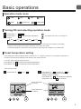
Basic operations
Operation mode icons
Cool
Dry
Fan
Auto
Auto cool
Heat
Auto heat
Turning ON and selecting operation mode
1
2
Press button 1 ( ON/OFF ).
Press button 7 ( F1 ) to go through the operation
modes.
Cool
Dry
*1
*1
Fan
Auto
The ON/OFF lamp and the LCD will light up.
F1
Heat
*1*2
*1
*1 Operation modes that are not available to the connected indoor unit models will not appear on the display.
*2 Single or dual set points will appear, depending on the indoor unit model.
* Interlocked operation is performed in all the operation modes when the ventilation unit is interlocked.
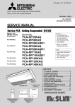
Preset temperature setting
Preset temperature will be displayed either in Celsius in 0.5- or 1-degree increments, or in Fahrenheit, depending on
the indoor unit model and the display mode setting on the remote controller.
<Cool, Dry, Heat, and Auto (single set point)>
Press button 8 ( F2 ) to decrease the preset temperature.
Press button 9 ( F3 ) to increase the preset temperature.
<Auto (dual set point)>
1
Press button 8 ( F2 ) or 9 ( F3 ).
Fri
Room
Mode
F1
Preset temperature
for cooling
Set Temp.
28
2
Auto
Temp.
F2
Press button 7 ( F1 ) or button 8 ( F2 ) to
move the cursor to the desired temperature
setting (cooling or heating).
Press button 9 ( F3 ) to decrease the selected
temperature, and 0 ( F4 ) to increase.
26
28
2
Auto
2
F3
Fan
F4
Preset temperature
for heating
Main display:
Cursor
F1
F2
Temp.
F3
F4
5
Operation mode
* The temperature range restriction setting will be applied
preferentially, if any. If the setting value is outside of the
range, a message "Temp. range locked" will appear. Refer to
the Instruction Book of the remote controller for details.
*1 The settable temperature range varies with the model of
indoor units.
*2 The preset temperature settings for cooling and heating in the
Auto (dual set point) mode are used by the Cool/Dry and Heat
modes.
The preset temperatures for cooling and heating in the Auto
(dual set point) mode can be set to meet the conditions below:
• Preset cooling temperature is higher than preset heating
temperature.
• The minimum temperature difference requirement
between cooling and heating preset temperatures (varies
with the models of indoor units connected) is met.
Preset temperature range
Cool/Dry
19 ~ 30 ºC (67 ~ 87 ºF) *1
Heat
17 ~ 28 ºC (63 ~ 83 ºF) *1
Auto
19 ~ 28 ºC (67 ~ 83 ºF) *1
(Single set point)
Auto
[Cool]
Preset temperature range for the
Cool mode
*2
[Heat]
Preset temperature range for the
Heat mode
(Dual set points)
Fan/Ventilation
Not settable
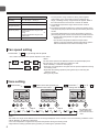
Fan speed setting
Press button 0 ( F4 ) to go through the fan speed.
* The number of available fan speeds depends on the model.
<Note>
The actual fan speed will be different from the fan speed displayed on
the LCD when one of the following conditions is met.
• While "Standby" or "Defrost" is displayed
• When the room temperature is higher than the preset temperature during
the heating mode
• Right after the heating operation (during stand by for switching the
operation mode)
• During the dry mode
Auto
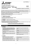
Vane setting
1
Press button 4 ( MENU ).
2
Set temp.
Auto
Temp.
Fan
Mode
F1
Auto
F2
F3
Step 1
3
Press button 7 ( F1 ) or 8 ( F2 )
to change the vane angle.
Fri
Main
Main menu
Vane·Louver·Vent. (Lossnay)
High power
Timer
Weekly timer
OU silent mode
Fri
Room
Cool
"Vane•Louver•Vent.(Lossnay)" is
selected. Press button 2 ( SELECT ).
Main display:
Cursor
F4
F1
Step 2
Step 3
F2
Vane
Page
F3
F4
Step 4
F1
Step 5
Swing
F2
Low
On
Vent.
Louver
F3
F4
* The settable vane
angle varies with
the model of indoor
units.
<Note>
The actual vane angle will be different from the vane angle displayed on the LCD when one of the following conditions is met.
• While "Standby" or "Defrost" is displayed
• The room temperature is higher than the preset temperature during the heating mode
• Right after the heating operation (during stand by for switching the operation mode)
6
Automatic cooling/heating operation
1
2
Press button 1 ( ON/OFF ).
Press button 7 ( F1 ) to display the operation mode "Auto".
<Auto (single set point)>
When the room temperature is higher than the preset temperature, cooling operation starts.
When the room temperature is lower than the preset temperature, heating operation starts.
F1
* The current operation mode ("Auto cool" or "Auto heat") will be displayed after the mode is determined.
If "Display/non-display of COOL/HEAT during AUTO mode" has been set to "Non-display" while making
the initial settings, only "Auto" will be displayed. Refer to the Installation Manual for details about initial
settings for the remote controller.
<Auto (dual set point)>
When the room temperature is higher than the preset cooling temperature, cooling operation starts.
When the room temperature is lower than the preset heating temperature, heating operation starts.
* When the operation mode is set to the Auto (dual set point) mode, only "Auto" will appear on the display, even
if the display setting of "Auto cool/Auto heat" is enabled.
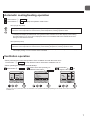
Ventilation operation
<When performing an interlocked operation of the ventilation unit with the indoor unit>
Press button 1 ( ON/OFF ) to turn both the indoor unit and the ventilation unit on.
<When operating the ventilation unit individually>
1
Press button 4 ( MENU ).
Fri
Room
Cool
Set temp.
Auto
Temp.
Fan
Mode
F1
F2
F3
F4
2
"Vane•Louver•Vent.(Lossnay)" is
selected. Press button 2 ( SELECT ).
3
Press button 9 ( F3 ) to
change the fan speed.
Fri
Main
Main menu
Vane·Louver·Vent. (Lossnay)
High power
Timer
Weekly timer
OU silent mode
Main display:
Cursor
F1
F2
Vane
Page
F3
F4
F1
F2
Low
On
Vent.
Louver
F3
F4
Indoor unit fan may operate even when the ventilation unit is operated individually, depending on the models of the indoor unit and the
ventilation unit.
7
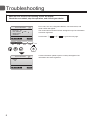
Troubleshooting
When an error occurs, the following screen will appear.
Check the error status, stop the operation, and consult your dealer.
Error code, error unit, refrigerant address, unit model name, and
serial number will appear.
The model name and serial number will appear only if the information
have been registered.
Error information
Error code
Error unit IU
Ref. address
Unt#
Model name
Serial No.
Press button 7 ( F1 ) or 8 ( F2 ) to go to the next page.
Reset error: Reset button
Page
Reset
F1
F2
F3
F4
Error information
Contact information
Dealer
Tel
Reset error: Reset button
Page
Reset
8
blinks
Contact information (dealer's phone number) will appear if the
information have been registered.
Timer, Weekly timer, Energy saving
The settings for Timer, Weekly timer, and Energy saving operation can be made from the remote controller.
Press button 4 ( MENU ) to go to the Main menu, and move the cursor to the desired setting with button 7 ( F1 )
or 8 ( F2 ). Refer to the Instruction Book of the remote controller for further information.
Main
Main menu
Vane·Louver·Vent. (Lossnay)
High power
Timer
Weekly timer
OU silent mode
Main display:
Cursor
F1
F2
Page
F3
F4
Main
Main menu
Restriction
Energy saving
Night setback
Filter information
Error information
Main display:
Cursor
F1
F2
Page
F3
F4
Timer
•
On/Off timer
Operation On/Off times can be set in 5-minute increments.
•
Auto-Off timer
Auto-Off time can be set to a value from 30 to 240 in 10-minute increments.
Weekly timer
Operation On/Off times for a week can be set.
Up to eight operation patterns can be set for each day.
Energy saving
•
Automatic return to the preset temperature
The units operate at the preset temperature after performing energy-save operation for a preset time period.
The preset time can be set to a value from 30 to 120 in 10-minute increments.
•
Setting the energy-saving operation schedule
The start/stop times to operate the units in the energy-save mode for each day of the week and the energy-saving
rate can be set.
Up to four operation patterns can be set for each day.
The times can be set in 5-minute increments.
The energy-saving rate range is 0% and 50 to 90% in 10% increments.
9
Maintenance
Filter information
Fri
will appear on the Main display in the Full mode when it
Room
Set temp.
Cool
Mode
is time to clean the filters.
Auto
Temp.
Fan
Resetting the filter sign
1
Select "Filter information"
from the Main menu and
press button 2 ( SELECT ).
Main
Main menu
Restriction
Energy saving
Night setback
Filter information
Error information
Main display:
Cursor
Page
F1
F2
F3
2
Press button 0 ( F4 )
to reset filter sign.
3
Select "OK" with
button 0 ( F4 ).
Main menu:
Cancel
Reset
F2
Filter information
Filter sign reset
Reset filter sign?
Main menu:
F1
A confirmation screen will
appear.
Filter information
Filter information
Please clean the filter.
Press Reset button after
filter cleaning.
F4
4
F3
F4
F1
F2
F3
OK
F4
F1
F2
F3
F4
<Note>
• Make sure to clean the filters before resetting filter sign. When the filter sign is reset, the cumulative operation time of the unit
will be reset.
• If two or more indoor units of different models are connected, the filter sign will appear when the filter on one of the indoor units
is due for cleaning. (long life filter: 2500 hours, general filter: 100 hours)
When the filter sign is reset, the cumulative operation time of all units will be reset.
• The filter sign is scheduled to appear after a certain duration of operation, based on the premise that the indoor units are
installed in a space with ordinary air quality. Depending on the air quality, the filter may require more frequent cleaning.
10
This product is designed and intended for use in the residential,
commercial, and light-industrial environment.
The product at hand is based on the following EU regulations:
• Low Voltage Directive 2006/95/EC
• Electromagnetic Compatibility Directive 2004/108/EC
HEAD OFFICE: TOKYO BLDG. , 2-7-3, MARUNOUCHI, CHIYODA-KU, TOKYO 100-8310, JAPAN
Authorized representative in EU: MITSUBISHI ELECTRIC EUROPE B.V.
HARMAN HOUSE, 1 GEORGE STREET, UXBRIDGE, MIDDLESEX UB8 1QQ, U.K.
WT06694X01