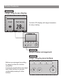
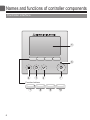
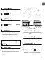
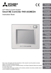
1
CITY MULTI Control System
and Mitsubishi Mr. Slim Air Conditioners
MA Remote Controller
PAR-31MAA
Instruction Book
Prior to use, thoroughly read the instructions in this manual to use the product correctly.
Retain for future reference.
Make sure that this CD-ROM and the Installation Manual are passed on to any future users.
To ensure safety and proper operation of the remote controller, the remote controller should
only be installed by qualified personnel.
Product features
Feature 1
Large, easy-to-see display
Cool
Set temp.
Mode
Temp.
Full-dot LCD display with large characters
for easy viewing
Feature 2
Simple button arrangement
Feature 3
Large, easy-to-press buttons
Buttons are arranged according
to usage to allow for intuitive
navigation.
Frequently used buttons are larger
than other buttons to prevent
unintended pressing of other
buttons.
Contents
Safety precautions .................................... 4
Names and functions of controller components......... 6
Controller interface ....................................................6
Display .......................................................................8
Read before operating the controller ......... 10
Menu structure.........................................................10
Icon explanations..................................................... 11
Basic operations .......................................... 12
Power ON/OFF ........................................................12
Operation mode, temperature, and fan speed settings..........14
Navigating through the menu ...................... 18
Main menu list .........................................................18
Restrictions for the sub remote controller ................19
Navigating through the Main menu..........................20
Controller operation-Function settings ....... 22
Vane•Louver•Vent. (Lossnay) ..................................22
High power ..............................................................24
Clock........................................................................25
Timer (On/Off timer).................................................26
(Auto-Off timer) ..............................................28
Weekly timer ............................................................30
OU silent mode ........................................................32
Restriction................................................................34
Energy saving ..........................................................38
Night setback ...........................................................42
Manual vane angle ..................................................44
Main display.............................................................46
Contrast ...................................................................47
Language selection .................................................48
Function setting .......................................................50
Maintenance ................................................. 52
Filter information ......................................................52
Troubleshooting ............................................ 54
Error information ......................................................54
Specifications ................................................ 56
Safety precautions
• Thoroughly read the following safety precautions before using the unit.
• Observe these precautions carefully to ensure safety.
WARNING
CAUTION
Indicates a risk of death or serious injury.
Indicates a risk of serious injury or structural damage.
• After reading this manual, pass it on to the end user to retain for future reference.
• Keep this manual for future reference and refer to it as necessary. This manual should be made available
to those who repair or relocate the controller. Make sure that the manual is passed on to any future
users.
General precautions
WARNING
Do not install the unit in a place where large
amounts of oil, steam, organic solvents, or corrosive
gases, such as sulfuric gas, are present or where
acidic/alkaline solutions or sprays are used
frequently. These substances can compromise
the performance of the unit or cause certain
components of the unit to corrode, which can result
in electric shock, malfunctions, smoke, or fire.
To reduce the risk of injury or electric shock, before
spraying a chemical around the controller, stop the
operation and cover the controller.
To reduce the risk of injury or electric shock, stop
the operation and switch off the power supply before
cleaning, maintaining, or inspecting the controller.
To reduce the risk of shorting, current leakage,
electric shock, malfunctions, smoke, or fire, do not
wash the controller with water or any other liquid.
If any abnormality (e.g., burning smell) is noticed,
stop the operation, turn off the power switch, and
consult your dealer. Continued use of the product
may result in electric shock, malfunctions, or fire.
To reduce the risk of electric shock, malfunctions,
smoke or fire, do not operate the switches/buttons or
touch other electrical parts with wet hands.
Properly install all required covers to keep moisture
and dust out of the controller. Dust accumulation and
water can cause electric shock, smoke, or fire.
When disinfecting the unit using alcohol, ventilate
the room adequately. The fumes of the alcohol
around the unit may cause a fire or explosion when
the unit is turned on.
CAUTION
To reduce the risk of fire or explosion, do not place
flammable materials or use flammable sprays
around the controller.
To reduce the risk of environmental pollution, consult
an authorized agency for proper disposal of remote
controller.
To reduce the risk of damage to the controller, do not
directly spray insecticide or other flammable sprays
on the controller.
To reduce the risk of electric shock or malfunctions,
do not touch the touch panel, switches, or buttons
with a pointy or sharp object.
4
To reduce the risk of injury and electric shock, avoid
contact with sharp edges of certain parts.
To reduce the risk of injury, wear protective gear
when working on the controller.
To avoid injury from broken glass, do not apply
excessive force on the glass parts.
Precautions for moving or repairing the controller
WARNING
The controller should be repaired or moved only by
qualified personnel. Do not disassemble or modify
the controller.
Improper installation or repair may cause injury,
electric shock, or fire.
CAUTION
To reduce the risk of shorting, electric shock, fire,
or malfunction, do not touch the circuit board with
tools or with your hands, and do not allow dust to
accumulate on the circuit board.
Additional precautions
To avoid damage to the controller, use appropriate
tools to install, inspect, or repair the controller.
This controller is designed for exclusive use with the
Building Management System by Mitsubishi Electric.
The use of this controller for with other systems or
for other purposes may cause malfunctions.
To avoid discoloration, do not use benzene, thinner,
or chemical rag to clean the controller. To clean the
controller, wipe with a soft cloth soaked in water with
mild detergent, wipe off the detergent with a wet
cloth, and wipe off water with a dry cloth.
To avoid damage to the controller, provide protection
against static electricity.
5
Names and functions of controller components
Controller interface
5
6
4
3
2
1
Function buttons
7
6
8
9
0
1 ON/OFF button
Press to turn ON/OFF the indoor unit.
2 SELECT button
Press to save the setting.
The functions of the function buttons
change depending on the screen.
Refer to the button function guide that
appears at the bottom of the LCD for
the functions they serve on a given
screen.
When the system is centrally
controlled, the button function guide
that corresponds to the locked button
will not appear.
3 RETURN button
Press to return to the previous screen.
Main display
Main menu
Fri
Room
4 MENU button
Page 20
Cool
Set temp.
Auto
Mode
Temp.
Fan
Main
Main menu
Vane·Louver·Vent. (Lossnay)
High power
Timer
Weekly timer
OU silent mode
Main display:
Cursor
Page
Press to bring up the Main menu.
7
8
9
0
7
8
9
0
Function guide
5 Backlit LCD
Operation settings will appear.
When the backlight is off, pressing any
button turns the backlight on and it
will stay lit for a certain period of time
depending on the screen.
7 Function button F1
Main display: Press to change the operation
mode.
Main menu: Press to move the cursor down.
8 Function button F2
Main display: Press to decrease temperature.
Main menu: Press to move the cursor up.
When the backlight is off, pressing any
button turns the backlight on and does
not perform its function. (except for the
ON/OFF button)
9 Function button F3
Main display: Press to increase temperature.
Main menu: Press to go to the previous page.
6 ON/OFF lamp
This lamp lights up in green while the unit
is in operation. It blinks while the remote
controller is starting up or when there is
an error.
0 Function button F4
Main display: Press to change the fan speed.
Main menu: Press to go to the next page.
7
Names and functions of controller components
Display
The main display can be displayed in two different modes: "Full" and "Basic."
The factory setting is "Full." To switch to the "Basic" mode, change the setting
on the Main display setting. (Refer to page 46.)
Full mode
b cd e f g h
* All icons are displayed for
explanation.
Fri
6
7
8
9
0
j
Room
Set temp.
Cool
3
i
Auto
1
4
a
Mode
Temp.
Fan
2
k
5
Basic mode
2
Fri
1
Cool
Mode
Set temp.
Temp.
5
8
Auto
Fan
3
4
1Operation mode
Page 14
Indoor unit operation mode appears here.
2Preset temperature
Page 15
Preset temperature appears here.
3Clock
(See the Installation Manual.)
Current time appears here.
4Fan speed
c
Page 26, 28, 42
Appears when the On/Off timer (Page 26), Night
setback (Page 42), or Auto-off timer (Page 28)
function is enabled.
appears when the timer is disabled by the
centralized control system.
d
Page 30
Appears when the Weekly timer is enabled.
Page 16
Page 40
Fan speed setting appears here.
e
5Button function guide
Appears while the units are operated in the
energy-save mode. (Will not appear on some
models of indoor units)
Functions of the corresponding buttons appear
here.
6
Appears when the ON/OFF operation is centrally
controlled.
7
Appears when the operation mode is centrally
controlled.
8
Appears when the preset temperature is centrally
controlled.
f
g
Appears when the built-in thermistor on the
remote controller is activated to monitor the
room temperature (a).
appears when the thermistor on the
indoor unit is activated to monitor the room
temperature.
9
h
Appears when the filter reset function is centrally
controlled.
Indicates the vane setting.
0
Page 52
Indicates when filter needs maintenance.
aRoom temperature
(See the Installation Manual.)
Current room temperature appears here.
b
Page 36
Appears when the buttons are locked.
Page 32
Appears while the outdoor units are operated in
the silent mode.
i
Page 22
Page 23
Indicates the louver setting.
j
Page 23
Indicates the ventilation setting.
k
Page 34
Appears when the preset temperature range is
restricted.
Most settings (except ON/OFF, mode, fan speed, temperature) can be made from the Menu
screen. (Refer to page 20.)
9
Read before operating the controller
Menu structure
Main menu
Press the
MENU button.
Vane•Louver•Vent. (Lossnay)
Page 22
High power
Page 24
Move the cursor
to the desired
item with
the F1 and
F2 buttons,
and press
the SELECT
button.
Timer
On/Off timer
Page 26
Auto-Off timer
Page 28
Weekly timer
Page 30
OU silent mode
Page 32
Restriction
Temp. range
Page 34
Operation lock
Page 36
Energy saving
Auto return
Page 38
Schedule
Page 40
Night setback
Page 42
Filter information
Page 52
Error information
Page 54
Maintenance
Auto descending panel
Refer to the Instructions Manual that
came with the automatic elevating panel.
Manual vane angle
Page 44
Initial setting
10
Main/Sub
Refer to the Installation Manual.
Clock
Page 25
Main display
Page 46
Contrast
Page 47
Display details
Refer to the Installation Manual.
Auto mode
Refer to the Installation Manual.
Administrator password
Refer to the Installation Manual.
Language selection
Page 48
Service
Test run
Refer to the indoor unit Installation
Manual.
Input maintenance info.
Refer to the indoor unit Installation
Manual.
Function setting
(Mr. Slim)
Function setting
(City Multi)
Lossnay (City Multi only)
Refer to the Installation Manual.
Check
Self check
Refer to the indoor unit Installation
Manual.
Refer to the Installation Manual.
Maintenance password
Refer to the Installation Manual.
Remote controller check
Refer to the Installation Manual.
Refer to page 50.
Refer to the Installation Manual.
Not all functions are available on all models of indoor units.
Icon explanations
Controller operation
Timer
P
P
The table below
summarizes the square
icons used in this manual.
The administrator or maintenance user password must be entered
on the password input screen to change settings. There is no
settings that can skip this process.
Main
Timer
Enter administrator password
Select:
Cursor
F1
ON
F2
F3
F4
Indicates settings that can be
changed only while the units
are in operation.
Indicates settings that can be
changed only while the units
are operated in the Cool,
Heat, or Auto mode.
F1
F2
F3
F4
: Press to move the cursor left.
: Press to move the cursor right.
: Press to decrease the value by 1.
: Press to increase the value by 1.
*Changes cannot be made unless the
correct password is entered.
OFF
Indicates
settings that
can be made
only from the
main remote
controller.
Indicates settings that can be changed
only while the units are not in operation.
Indicates functions that are not available
when the buttons are locked or the
system is centrally controlled.
11
Basic operations
Power ON/OFF
Button operation
ON
Press the ON/OFF button.
The ON/OFF lamp will light up in green, and the
operation will start.
OFF
Press the ON/OFF button again.
The ON/OFF lamp will come off, and the operation will
stop.
12
Operation status memory
Remote controller setting
Operation mode
Operation mode before the power was turned off
Preset temperature
Preset temperature before the power was turned off
Fan speed
Fan speed before the power was turned off
Settable preset temperature range
Operation mode
Preset temperature range
Cool/Dry
19 ~ 30 ºC (67 ~ 87 ºF)
Heat
17 ~ 28 ºC (63 ~ 83 ºF)
Auto (Single set point)
19 ~ 28 ºC (67 ~ 83 ºF)
Auto (Dual set points)
[Cool]
Preset temperature range for the Cool mode
[Heat]
Preset temperature range for the Heat mode
Fan/Ventilation
Not settable
The settable temperature range varies with the model of indoor units.
13
Basic operations
Operation mode, temperature, and fan speed settings
ON
Button operation
Operation mode
Fri
Room
Press the F1 button to go through the operation
modes in the order of "Cool, Dry, Fan, Auto, and
Heat." Select the desired operation mode.
Cool
Set temp.
Auto
Mode
Temp.
Fan
Cool
Dry
F4
Auto
Heat
F1
F2
F3
Fan
•Operation modes that are not available to the connected
indoor unit models will not appear on the display.
What the blinking mode icon means
The mode icon will blink when other indoor units in the same refrigerant system (connected to the same
outdoor unit) are already operated in a different mode. In this case, the rest of the unit in the same
group can only be operated in the same mode.
<AUTO (dual set point) mode>
When the operation mode is set to the Auto (dual set point) mode, two preset
temperatures (one each for cooling and heating) can be set. Depending on the room
temperature, indoor unit will automatically operate in either the Cool or Heat mode
and keep the room temperature within the preset range.
The graph below shows the operation pattern of indoor unit operated in the Auto
(dual set point) mode.
Operation pattern during Auto (dual set point) mode
The room temperature
changes corresponding
to the change in the
outside temperature.
Preset temp.
(COOL)
Room temperature
Preset temp.
(HEAT)
HEAT
14
COOL
HEAT
COOL
Preset temperature
<Cool, Dry, Heat, and Auto (single set point)>
Fri
Room
Cool
Set temp.
Auto
Mode
Temp.
Fan
F1
F2
F3
F4
Press the F2 button to decrease the preset
temperature, and press the F3 button to
increase.
•Refer to the table on page 13 for the settable
temperature range for different operation modes.
•Preset temperature range cannot be set for Fan/
Ventilation operation.
•Preset temperature will be displayed either in
Centigrade in 0.5- or 1-degree increments, or in
Fahrenheit, depending on the indoor unit model and the
display mode setting on the remote controller.
Fri
Room 28.5
Cool
Mode
Set temp.
28.5
Temp.
Auto
Fan
Example display
(Centigrade in 0.5-degree increments)
<Auto (dual set point) mode>
1
Preset
temperature
for cooling
Preset
temperature
for heating
Fri
Room
Mode
F1
26
28
2
Auto
Auto
Temp.
F2
F3
The current preset temperatures will appear.
Press the F2 or F3 button to display the
Settings screen.
Fan
F4
15
Basic operations
2
28
2
Preset
temperature
for cooling
Preset
temperature
for heating
Press the F1 or F2 button to move the cursor
to the desired temperature setting (cooling or
heating).
Press the F3 button to decrease the selected
temperature, and F4 to increase.
Set Temp.
Main display:
Cursor
F1
Temp.
F2
F3
F4
•Refer to the table on page 13 for the settable
temperature range for different operation modes.
•The preset temperature settings for cooling and heating
in the Auto (dual set point) mode are also used by the
Cool/Dry and Heat modes.
•The preset temperatures for cooling and heating in the
Auto (dual set point) mode must meet the conditions
below:
• Preset cooling temperature is higher than preset heating temperature.
• The minimum temperature difference requirement between cooling
and heating preset temperatures (varies with the models of indoor units
connected) is met.
* If preset temperatures are set in a way that does not meet
the minimum temperature difference requirement, both preset
temperatures will automatically be changed within the allowable setting
ranges.
Navigating through the screens
• To return to the Main screen ...... RETURN button
Fan speed
Fri
Press the F4 button to go through the fan
speeds in the following order.
Room
Cool
Set temp.
Auto
Mode
Temp.
Fan
Auto
F1
F2
F3
F4
•The available fan speeds depend on the models of connected
indoor units.
16
17
Navigating through the menu
Main menu list
Setting and display
items
Vane•Louver•Vent.
(Lossnay)
High power
Setting details
Use to set the vane angle.
•Select a desired vane setting from five different settings.
Use to turn ON/OFF the louver.
•Select a desired setting from "ON" and "OFF."
Use to set the amount of ventilation.
•Select a desired setting from "Off," "Low," and "High."
Use to reach the comfortable room temperature quickly.
•Units can be operated in the High-power mode for up to 30
minutes.
Timer
On/Off
Use to set the operation On/Off times.
timer
•Time can be set in 5-minute increments.
* Clock setting is required.
Auto-Off Use to set the Auto-Off time.
timer
•Time can be set to a value from 30 to 240 in 10-minute increments.
Weekly timer
Use to set the weekly operation On/Off times.
•Up to eight operation patterns can be set for each day.
* Clock setting is required.
* Not valid when the On/Off timer is enabled.
OU silent mode
Use to set the time periods in which priority is given to quiet
operation of outdoor units over temperature control. Set the
Start/Stop times for each day of the week.
•Select the desired silent level from "Normal," "Middle," and "Quiet."
* Clock setting is required.
Restriction Temp.
Use to restrict the preset temperature range.
range
•Different temperature ranges can be set for different operation
modes.
Operation Use to lock selected functions.
lock
•The locked functions cannot be operated.
Energy
Auto
Use to get the units to operate at the preset temperature after
saving
return
performing energy-save operation for a specified time period.
•Time can be set to a value from 30 and 120 in 10-minute
increments.
* This function will not be valid when the preset temperature ranges
are restricted.
Schedule Set the start/stop times to operate the units in the energy-save
mode for each day of the week, and set the energy-saving rate.
•Up to four energy-save operation patterns can be set for each day.
•Time can be set in 5-minute increments.
•Energy-saving rate can be set to a value from 0% and 50 to 90% in
10% increments.
* Clock setting is required.
18
Reference
page
22
24
26
28
30
32
34
36
38
40
Setting and display
items
Night setback
Setting details
Use to make Night setback settings.
•Select "Yes" to enable the setting, and "No" to disable the setting.
The temperature range and the start/stop times can be set.
* Clock setting is required.
Filter information
Use to check the filter status.
•The filter sign can be reset.
Error information
Use to check error information when an error occurs.
•Error code, error source, refrigerant address, unit model,
manufacturing number, contact information (dealer's phone
number) can be displayed.
* The unit model, manufacturing number, and contact information
need to be registered in advance to be displayed.
Maintenance Manual vane Use to set the vane angle for each vane to a fixed position.
angle
Initial
Clock
Use to set the current time.
setting
Main
Use to switch between "Full" and "Basic" modes for the Main
display
display.
•The default setting is "Full."
Contrast Use to adjust screen contrast.
Language Use to select the desired language.
selection
Service
Function Use to make settings for indoor unit's functions.
setting
Reference
page
42
52
54
44
25
46
47
48
50
(City Multi)
Restrictions for the sub remote controller
Main
Main menu
Vane·Louver·Vent. (Lossnay)
High power
Timer
Weekly timer
OU silent mode
Main display:
Cursor
Page
The following settings cannot be made
from the sub remote controller. Make these
settings from the main remote controller.
"Main" is displayed in the title of the Main
menu on the main remote controller.
•Timer
(On/Off timer, Auto-Off timer)
•Weekly timer
•OU silent mode
•Energy saving
(Auto return, Schedule)
•Night setback
•Maintenance
(Manual vane angle)
19
Navigating through the menu
Navigating through the Main menu
Button operation
Accessing the Main menu
Main
Main menu
Vane·Louver·Vent. (Lossnay)
High power
Timer
Weekly timer
OU silent mode
Main display:
Cursor
F1
F2
Press the MENU button.
The Main menu will appear.
Page
F3
F4
Item selection
Cursor
Press F1 to move the cursor down.
Press F2 to move the cursor up.
Main
Main menu
Vane·Louver·Vent. (Lossnay)
High power
Timer
Weekly timer
OU silent mode
Main display:
Cursor
Page
F1
F2
F3
F4
Navigating through the pages
Main menu
Main
Vane·Louver·Vent. (Lossnay)
High power
Timer
Weekly timer
OU silent mode
Main display:
Cursor
Page
F1
20
F2
F3
F4
Page
Press F3 to go to the previous page.
Press F4 to go to the next page.
Saving the settings
OU silent mode
Mon Tue Wed Thu Fri Sat Sun
Start
Stop Silent
-
The screen to set the selected item will appear.
Setting display:
day
F1
F2
Select the desired item, and press the SELECT
button.
F3
F4
Exiting the Main menu screen
Fri
Room
Cool
Set temp.
Auto
Mode
Temp.
Fan
F1
F2
F3
Press the RETURN button to exit the Main
menu and return to the Main display.
F4
If no buttons are touched for 10 minutes, the screen will automatically return to the
Main display. Any settings that have not been saved will be lost.
Display of unsupported functions
Title
The message at left will appear if the user
selects a function not supported by the
corresponding indoor unit model.
Not available
Unsupported function
Return:
F1
F2
F3
F4
21
Controller operation-Function settings
Vane•Louver•Vent. (Lossnay)
ON
Button operation
Accessing the menu
Select "Vane•Louver•Vent. (Lossnay)" from the
Main
Main menu
Vane·Louver·Vent. (Lossnay)
High power
Timer
Weekly timer
OU silent mode
Main display:
Cursor
F1
Main menu (refer to page 20), and press the
SELECT button.
Page
F2
F3
F4
Vane setting
Fri
Swing
Off
Off
Vane
Vent.
Louver
F1
F2
F3
Press the F1 or F2 button to go through the
vane setting options: "AUTO," "Step 1," "Step 2,"
"Step 3," "Step 4," "Step 5," and "Swing."
Select the desired setting.
Auto
Auto
Step 1
Step 2
Step 3
Step 4
Step 5
F4
Swing
(Sample screen on City Multi)
Swing
Select "Swing" to move the vanes up and down
automatically.
When set to "Step 1" through "Step 5", the vane
will be fixed at the selected angle.
Fri
Room
Cool
Mode
22
Set temp.
Auto
Temp.
Fan
•
under the vane setting icon
This icon will appear when the vane is set to "Step 5"
and the fan operates at low speed during cooling or
dry operation (depends on the model).
The icon will go off in an hour, and the vane setting
will automatically change.
Louver setting
Fri
Off
On
Press the F4 button to turn the louver swing ON
and OFF.
Off
Vane
F1
F2
Vent.
Louver
F3
F4
Off
On
On
(Sample screen on City Multi)
Vent. setting
Fri
Low
Press the F3 button to go through the
ventilation setting options in the order of "Off,"
"Low," and "High."
* Settable only when LOSSNAY unit is connected.
Vent.
Off
Low
Off
F1
F2
F3
F4
High
Low
High
• The fan on some models of indoor units may be
interlocked with certain models of ventilation units.
(Sample screen on Mr. Slim)
Returning to the Main menu
Main
Main menu
Vane·Louver·Vent. (Lossnay)
High power
Timer
Weekly timer
OU silent mode
Main display:
Cursor
F1
F2
Press the RETURN button to go back to the
Main menu.
Page
F3
F4
23
Controller operation-Function settings
High power
ON
Function description
High-power operation function allows the units to operate at higher-than-normal capacity so that the
room air can be conditioned to an optimum temperature quickly. This operation will last for up to 30
minutes, and the unit will return to the normal operation mode at the end of the 30 minutes or when
the room temperature reaches the preset temperature, whichever is earlier. The units will return to the
normal operation when the operation mode or fan speed is changed.
Button operation
1
Main
Main menu
Vane·Louver·Vent. (Lossnay)
High power
Timer
Weekly timer
OU silent mode
Main display:
Cursor
F1
F2
Select "High power" from the Main menu during
Cooling, Heating, or AUTO operation (refer to
page 20), and press the SELECT button.
Page
F3
F4
"High power" function is available only on the
models that support the function.
2
Move the cursor to "YES" with the F3 or F4
button, and press the SELECT button.
High power
High power No / Yes
Select:
Cursor
F1
F2
F3
F4
High power
High power No / Yes
High power operation selected
Main menu:
24
A confirmation screen will appear.
Navigating through the screens
• To go back to the Main menu ........... MENU button
• To return to the previous screen ....... RETURN button
Clock
P
Button operation
1
Select "Initial setting" from the Main menu (refer
to page 20), and press the SELECT button.
Main
Main menu
Maintenance
Initial setting
Service
Main display:
Cursor
F1
2
Page
F2
F3
F4
Clock setting is required before making the
following settings.
• On/Off timer
• Weekly timer
• OU silent mode
• Energy saving
• Night setback
Move the cursor to the "Clock" with the F1 or
F2 button, and press the SELECT button.
Initial setting menu
Main/Sub
Clock
Main display
Contrast
Display details
Main menu:
Cursor
F1
3
Page
F2
F3
F4
Clock
yyyy / mm/ dd
hh: mm
:
1 / 1
2 12 /
Select:
Cursor
F1
F2
F3
F4
Move the cursor to the desired item with the F1
or F2 button out of year, month, date, hour, or
minute.
Increase or decrease the value for the selected
item with the F3 or F4 button, and press the
SELECT button.
A confirmation screen will appear.
Navigating through the screens
• To go back to the Main menu .......... MENU button
• To return to the previous screen ...... RETURN button
25
Controller operation-Function settings
Timer
Main
P
On/Off timer
Button operation
1
Main
Main menu
Vane·Louver·Vent. (Lossnay)
High power
Timer
Weekly timer
OU silent mode
Main display:
Cursor
F1
2
F2
F4
F3
F1
F2
Move the cursor to the On/Off timer, and press
the SELECT button.
F4
Cursor
F3
The On/Off timer will not work in the following cases:
when On/Off timer is disabled, during an error, during
check (in the service menu), during test run, during
remote controller diagnosis, when the clock is not set,
during Function setting, when the system is centrally
controlled (when On/Off operation or Timer operation from
local remote controller is prohibited).
The current settings will appear.
Timer
On/Off timer
No / Yes
On
Off
Repeat
No / Yes
Select:
Cursor
26
F3
Timer
On/Off timer
Yes
On
Off
Repeat No
Auto-off
No
--- min
Stop in
Setting display:
Cursor
F1
3
F2
Page
Select "Timer" from the Main menu (refer to page
20), and press the SELECT button.
F4
The screen to set the timer will appear.
Select the desired item with the F1 or F2
button out of "On/Off timer," "On," "Off," or
"Repeat."
4
Select:
Cursor
F1
5
Change the setting with the F3 or F4 button.
• On/Off timer: No (disable)/Yes (enable)
• On: Operation start time
(settable in 5-minute increments)
* Press and hold the button to rapidly advance
the numbers.
• Off: Operation stop time
(settable in 5-minute increments)
* Press and hold the button to rapidly advance
the numbers.
• Repeat: No (once)/Yes (repeat)
Timer
On/Off timer
No / Yes
On
Off
Repeat
No / Yes
Time
F2
F3
F4
Press the SELECT button to save the settings.
Timer
On/Off timer
No / Yes
On
Off
Repeat
No / Yes
Select:
Cursor
F1
Time
F2
F3
F4
A confirmation screen will appear.
Timer
On/Off timer
No / Yes
On
Off
Repeat
No / Yes
Changes saved
Main menu:
Navigating through the screens
• To go back to the Main menu .......... MENU button
• To return to the previous screen ...... RETURN button
Fri
Cool
Mode
Room
Set temp.
Temp.
Auto
will appear on the Main display in the Full
mode when the On/Off timer is enabled.
appears when the timer is disabled by the
centralized control system.
Fan
27
Controller operation-Function settings
Timer
Main
P
Auto-Off timer
Button operation
1
F1
2
F2
F1
F2
F4
F1
F2
The Auto-Off timer will not work in the following cases:
when Auto-Off timer is disabled, during an error, during
check (in the service menu), during test run, during
remote controller diagnosis, during Function setting, when
the system is centrally controlled (when On/Off operation
or Timer operation from local controller is prohibited).
The current settings will appear.
Move the cursor to the "Auto-Off" or "Stop in --min" with the F1 or F2 button.
Cursor
F3
F4
Change the setting with the F3 or F4 button.
Auto-Off timer
Auto-Off
No Yes
Stop in
min
Select:
Cursor
28
F3
Select "Auto-Off", and press the SELECT
button.
Auto-Off timer
Auto-Off
No Yes
Stop in
min
Select:
Cursor
3
Bring up the Timer setting screen.
(Refer to page 26.)
Timer
On/Off timer
Yes
On
Off
Repeat No
Auto-Off
No
--- min
Stop in
Setting display:
Cursor
• Auto-Off: No (disable)/Yes (enable)
• Stop in --- min: Timer setting (The settable
range is 30 to 240 minutes in
10-minute increments.)
Time
F3
F4
4
Press the SELECT button to save the settings.
Auto-Off timer
Auto-Off
No Yes
Stop in
min
Select:
Cursor
F1
Time
F2
F3
F4
A confirmation screen will appear.
Auto-Off timer
Auto-Off
No Yes
Stop in
min
Navigating through the screens
Changes saved
• To go back to the Main menu .......... MENU button
Main menu:
• To return to the previous screen ...... RETURN button
Fri
will appear on the Main display in the
Full mode when the Auto-Off timer is enabled.
Cool
Room
Set temp.
Auto
appears when the timer is disabled by the
centralized control system.
Mode
Temp.
Fan
29
Controller operation-Function settings
Weekly timer
Main
P
Button operation
1
Main
Main menu
Vane·Louver·Vent. (Lossnay)
High power
Timer
Weekly timer
OU silent mode
Main display:
Cursor
F1
2
F2
Page
F3
Weekly timer
Mon Tue Wed Thu Fri Sat Sun
No.
Setting display:
day
F1
3
F4
F2
Page
F3
F4
The Weekly timer will not work in the following cases:
when the On/Off timer is enabled, when the weekly timer
is disabled, during an error, during check (in the service
menu), during test run, during remote controller diagnosis,
when the clock is not set, during Function setting, when
the system is centrally controlled (On/Off operation,
temperature setting, or Timer operation from local remote
controller is prohibited).
The current settings will appear.
Press the F1 or F2 button to see the settings
for each day of the week.
Press the F4 button to see patterns 5 through 8.
Press the SELECT button to go to the setting
screen.
The screen to enable (Yes) and disable (No) the
weekly timer will appear.
Weekly timer
Weekly timer No / Yes
Select:
Cursor
F1
30
Select "Weekly timer" from the Main menu (refer
to page 20), and press the SELECT button.
F2
F3
F4
To enable the setting, move the cursor to "Yes"
with the F3 or F4 button, and press the
SELECT button.
4
The weekly timer setting screen will appear and
the current settings will be displayed.
Up to eight operation patterns can be set for
each day.
Move the cursor to the desired day of the week
with the F1 or F2 button, and press the
F3 button to select it. (Multiple days can be
selected.)
Weekly timer
Mon Tue Wed Thu Fri Sat Sun
No.
Input display:
day
F1
F2
Select
Page
F3
F4
Press the SELECT button.
5
No.
Select:
Cursor
F1
Operation pattern setting screen will appear.
Press the F1 button to move the cursor to the desired
pattern number.
Move the cursor to the time, On/Off, or temperature
with the F2 button.
Change the settings with the F3 or F4 button.
Weekly timer
Thu
On
6: 3
1 :
Auto 2 - 27
• Time: settable in 5-minute increments
* Press and hold the button to rapidly advance the numbers.
• On/Off/Auto: Selectable settings depend on the model of
connected indoor unit. (When an Auto pattern is executed,
the system will operate in the Auto (dual set point) mode.)
• Temperature: The settable temperature range
depends on the connected indoor units. (1ºC increments)
When the Auto (dual set point) mode is selected, two preset
temperatures can be set. If an operation pattern with a single
preset temperature setting is executed during the Auto
(dual set point) mode, its setting will be used as the cooling
temperature setting in the Cool mode.
Content
F2
F3
F4
Weekly timer
Thu
Press the SELECT button to save the settings.
A confirmation screen will appear.
Navigating through the screens
Changes saved
• To go back to the setting change/day of the week
selection screen ............................. SELECT button
• To go back to the Main menu .......... MENU button
• To return to the previous screen ...... RETURN button
Day selection:
Fri
Cool
Mode
Room
Set temp.
Temp.
Auto
Fan
will appear on the Main display in the Full
mode when the weekly timer setting for the
current day exists.
The icon will not appear while the On/Off timer
is enabled or the system is under centralized
control (Timer operation from local remote
controller is prohibited).
31
Controller operation-Function settings
OU silent mode
Main
P
Function description
This function allows the user to set the time periods in which priority is given to quiet operation of
outdoor units over temperature control. Set the start and stop times each day of the week for the quiet
operation. Select the desired silent level from "Middle" and "Quiet".
Button operation
1
Main
Main menu
Vane·Louver·Vent. (Lossnay)
High power
Timer
Weekly timer
OU silent mode
Main display:
Cursor
Page
F1
2
F2
F3
F4
OU silent mode
Mon Tue Wed Thu Fri Sat Sun
Start
Stop Silent
-
Setting display:
day
F1
3
F2
F3
32
Press the F1 or F2 button to see the settings
for each day of the week.
Press the SELECT button to go to the setting
screen.
No / Yes
Cursor
F2
The current settings will appear.
The screen to enable (Yes) and disable (No) the
silent mode will appear.
Select:
F1
"OU silent mode" function is available only on the
models that support the function.
F4
OU silent mode
OU silent mode
Select "OU silent mode" from the Main menu
(refer to page 20), and press the SELECT
button.
F3
F4
To enable this setting, move the cursor to "Yes"
with the F3 or F4 button, and press the
SELECT button .
4
The OU silent mode setting screen will appear.
OU silent mode
Mon Tue Wed Thu Fri Sat Sun
Start
Stop Silent
-
To make or change the setting, move the cursor
to the desired day of the week with the F1 or
F2 button, and press the F3 button to select it.
(Multiple days can be selected.)
Select:
day
F1
5
Select
F2
F3
F4
Press the SELECT button.
The setting screen will appear.
Move the cursor to the desired item with the F1
or F2 button out of Start time, Stop time, or
Silent level.
Change the settings with the F3 or F4 button.
• Start/Stop time: settable in 5-minute increments
* Press and hold the button to rapidly advance
the numbers.
• Silent level: Normal, Middle, Quiet
OU silent mode
Start
Sat
Silent
Stop
-
Select:
Cursor
F1
Content
F2
F3
F4
Normal
Sat
Navigating through the screens
Changes saved
Day selection:
• To go back to the setting change/day of the week
selection screen ............................. SELECT button
• To go back to the Main menu .......... MENU button
• To return to the previous screen ...... RETURN button
Fri
Mode
Room
Set temp.
Temp.
Quiet
Press the SELECT button to save the settings.
A confirmation screen will appear.
OU silent mode
Cool
Middle
will appear on the Main display in the Full
mode during the OU silent mode.
Auto
Fan
33
Controller operation-Function settings
Restriction
P
Setting the temperature range restriction
Button operation
1
Main display:
Cursor
F1
2
Select "Restriction" from the Main menu (refer to
page 20), and press the SELECT button.
Main
Main menu
Restriction
Energy saving
Night setback
Filter information
Error information
F2
Page
F3
F4
The current settings will appear.
Restriction
Temp. range Yes
Cool·Dry
Heat
Auto
Move the cursor to "Temp. range" with the F1 or
F2 button, and press the SELECT button.
Setting display:
Page
F1
3
F2
F3
F4
The screen to set the temperature range will
appear.
Temp. range
Temp. range No / Yes
Cool·Dry
Heat
Auto
Select:
Cursor
Move the cursor to the desired item with the F1
button out of "Temp. range," "Cool•Dry," "Heat,"
Cursor
or "Auto."
F1
34
F2
F3
F4
4
Change the settings with the F3 or F4 button.
• Temp. range: No (unrestricted) or
Yes (restricted)
• Cool•Dry: Upper and lower limit temperature
Temp. range
Temp. range No / Yes
Cool·Dry
Heat
Auto
(1ºC increments)
Select:
Cursor
F1
Temp.
F2
F3
• Heat: Upper and lower limit temperature (1ºC increments)
• Auto: Upper and lower limit temperature (1ºC increments)
F4
Temperature setting ranges
Mode
Lower limit
*1
19 ~ 30ºC
Cool•Dry *3
(67 ~ 87ºF)
17 ~ 28ºC
*2
Heat
*3
(63 ~ 83ºF)
19 ~ 28ºC
*4
Auto
(67 ~ 83ºF)
Temp. range
Temp. range No / Yes
Cool·Dry
Heat
Auto
Changes saved
Main menu:
Upper limit
30 ~ 19ºC
(87 ~ 67ºF)
28 ~ 17ºC
(83 ~ 63ºF)
28 ~ 19ºC
(83 ~ 67ºF)
* The settable range varies depending on the connected unit.
*1 Temperature ranges for the Cool, Dry, and Auto (dual set
point) modes can be set.
*2 Temperature ranges for the Heat and Auto (dual set point)
modes can be set.
*3 Temperature ranges for the Heat, Cool, and Dry modes
must meet the conditions below:
• Upper limit for cooling - upper limit for heating ≥ Minimum
temperature difference (varies with indoor unit model)
• Lower limit for cooling - lower limit for heating ≥ Minimum
temperature difference (varies with indoor unit model)
*4 Temperature range for the Auto (single set point) mode can
be set.
Press the SELECT button to save the settings.
A confirmation screen will appear.
Navigating through the screens
• To go back to the Main menu .......... MENU button
• To return to the previous screen ...... RETURN button
Fri
Cool
Mode
Room
Set temp.
Temp.
will appear on the Main display in the Full
mode when the temperature range is restricted.
Auto
Fan
35
Controller operation-Function settings
Restriction
P
Operation lock function
To enable the operation lock function, set
the item "Operation locked" to " Yes".
Button operation
1
Bring up the Restriction setting screen. (Refer to
page 34.)
Restriction
Operation locked No
On/Off Mode Set temp.
Vane
Move the cursor to "Operation locked" and press
the SELECT button.
Setting display:
Page
F1
2
F2
F3
F4
Restriction
Operation locked No / Yes
On/Off
Locked
Mode
Locked
Set temp.
Locked
Vane
Locked
Select:
Cursor
Cursor
F1
F2
F3
Restriction
Operation locked Yes
On/Off Mode Set temp.
Vane
Changes saved
Main menu:
F4
The screen to make the settings for the operation
lock function will appear.
Move the cursor to the desired item with the F1
or F2 button out of "Operation locked," "On/Off,"
"Mode," "Set temp.," or "Vane."
Change the settings with the F3 or F4 button.
• Operation locked: No (disable)/Yes (enable)
• On/Off: On/Off operation
• Mode: Operation mode setting
"-" / "Locked"
• Set temp.: Preset temp. setting
• Vane: Vane setting
Press the SELECT button to save the settings.
A confirmation screen will appear.
Navigating through the screens
• To go back to the Main menu .......... MENU button
• To return to the previous screen ...... RETURN button
36
Fri
Cool
Mode
Room
Set temp.
Auto
will appear on the Main display in the Full
mode when the operation lock function setting is
enabled.
Operation guide that corresponds to the locked
function will be suppressed.
Fan
(When Set temp. is locked)
37
Controller operation-Function settings
Energy saving
Main
P
Automatic return to the preset temperature
Button operation
1
F1
2
F3
F4
F2
F3
F2
F3
The current settings will appear.
Move the cursor to "Auto return" with the F1 or
F2 button, and press the SELECT button.
F4
Auto return
Auto return
No / Yes
Cool: After min
back to
Heat: After min
back to
Select:
Cursor
Cursor
F1
38
F2
Energy saving
Auto return
Yes
Cool:
min,
Heat:
min,
Schedule
No
Mon Tue Wed Thu Fri Sat Sun
Setting display:
Cursor
F1
3
Select "Energy saving" from the Main menu
(refer to page 20), and press the SELECT
button.
Main
Main menu
Restriction
Energy saving
Night setback
Filter information
Error information
Main display:
Cursor
Page
F4
The screen to make the settings for the
automatic return to the preset temperature will
appear.
Move the cursor to the desired item with the F1
or F2 button out of "Auto return," "Cool," or
"Heat."
4
Change the settings with the F3 or F4 button.
• Auto return: No (disable)/Yes (enable)
• Cool: Timer setting range is 30 to 120 minutes
in 10-minute increments.
Temperature setting range is 19 to 30ºC
(67 to 87ºF) (1ºC increments).
• Heat: Timer setting range is 30 to 120 minutes
in 10-minute increments.
Temperature setting range is 17 to 28ºC
(63 to 83ºF) (1ºC increments).
Auto return
Auto return
No / Yes
Cool: After
min
back to
Heat: After
min
back to
Select:
Cursor
Content
F1
F2
F3
F4
Press the SELECT button to save the settings.
"Cool" includes "Dry" and "AUTO Cooling"
modes, and "Heat" includes "AUTO Heating"
mode.
The screen to set the selected item will appear.
Auto return
Auto return
Yes
Cool:
min,
Heat:
min,
Changes saved
Main menu:
Navigating through the screens
• To go back to the Main menu ........... MENU button
• To return to the previous screen ...... RETURN button
The above Timer or Preset temperature settings will not be effective when the Temp. range is
restricted and when the system is centrally controlled (when the Temp. range setting from local
controller is prohibited). When the system is centrally controlled (when Timer operation from
local remote controller is prohibited), only the Timer setting will be ineffective.
<Sample screens when the Auto return function is enabled>
Example: Lower the Set temp. to 24ºC (75ºF). 60 minutes later, the Set temp. will be back to 28ºC (83ºF).
Fri
Fri
60
minutes
later
Fri
Cool
Set temp.
Auto
Cool
Set temp.
Auto
Cool
Set temp.
Auto
Mode
Temp.
Fan
Mode
Temp.
Fan
Mode
Temp.
Fan
The Set temp. is changed
from 28ºC (83ºF) to 24ºC
(75ºF) by a user.
60 minutes later, the Set
temp. returns to 28ºC (83ºF)
automatically.
39
Controller operation-Function settings
Energy saving
Main
P
Setting the energy-saving operation schedule
Button operation
1
Energy saving
Auto return
Yes
Cool:
min,
Heat:
min,
Schedule
No
Mon Tue Wed Thu Fri Sat Sun
Setting display:
Cursor
F1
2
F3
F2
F3
The screen to see the schedule will appear.
Press the F1 or F2 button to see the settings
for each day of the week.
Press the SELECT button to go to the setting
screen.
F4
The screen to enable (Yes)/disable (No) the
energy-saving operation schedule will appear.
Energy saving
Energy saving No / Yes
Select:
Cursor
F1
40
Move the cursor to the "Schedule," and press the
SELECT button.
F4
Energy saving
Mon Tue Wed Thu Fri Sat Sun
No.
Setting display:
day
F1
3
F2
Bring up the "Energy saving" screen. (Refer to
page 38.)
F2
F3
F4
Select "No" or "Yes" with the F3 or F4 button.
Press the SELECT button to go to the setting
change/day of the week selection screen.
4
The setting change/day of the week selection
screen will appear.
Up to four operation patterns can be set for each
day.
Move the cursor to the desired day of the week
with the F1 or F2 button, and press the
F3 button to select it. (Multiple days can be
selected.)
Press the SELECT button to go to the pattern
setting screen.
Energy saving
Mon Tue Wed Thu Fri Sat Sun
No.
Input:
day
F1
5
Select
F2
F3
F4
The pattern setting screen will appear.
Press the F1 button to move the cursor to the
desired pattern number.
Move the cursor to the desired item with the
F2 button out of the start time, stop time, and
energy-saving rate (arranged in this order from
the left).
Change the settings with the F3 or F4 button.
• Start/Stop time: settable in 5-minute increments
* Press and hold the button to rapidly advance
the numbers.
• Energy-saving rate: The setting range is 0%
and 50 to 90% in 10% increments.
Press the SELECT button to save the settings.
A confirmation screen will appear.
Energy saving
Mon
No.
Select:
Cursor
Content
F1
F2
F3
F4
Energy saving
Mon
Changes saved
Day selection:
The lower the value, the greater the energy-saving effect.
Fri
Cool
Mode
Room
Set temp.
Temp.
Auto
Fan
will appear on the Main display in the Full
mode when the unit is operated in the energy
saving mode.
Navigating through the screens
• To go back to the setting change/day of the week
selection screen ............................. SELECT button
• To go back to the Main menu .......... MENU button
• To return to the previous screen ...... RETURN button
41
Controller operation-Function settings
Night setback
Main
P
Function description
This control starts heating operation when the control object group is stopped and the room temperature
drops below the preset lower limit temperature. Also, this control starts cooling operation when
the control object group is stopped and the room temperature rises above the preset upper limit
temperature.
The Night setback function is not available if the operation and the temperature setting are performed
from the remote controller.
If the room temperature is measured by the air-conditioner's suction temperature sensor, the accurate
temperature may not be obtained when the air-conditioner is inactive or when the air is not clean. In
this case, switch the sensor to a remote sensor (PAC-SE40TSA/PAC-SE41TS-E) or a remote control
sensor.
Button operation
1
F1
2
Select "Night setback" from the Main menu (refer
to page 20), and press the SELECT button.
Main
Main menu
Restriction
Energy saving
Night setback
Filter information
Error information
Main display:
Cursor
Page
F2
F3
F4
Night setback
Night setback Yes
Temp. range 12
- 28
Start
23:00
Stop
5:00
Setting display:
F1
42
F2
F3
F4
The current settings will appear.
Press the SELECT button to go to the setting
screen.
3
Move the cursor to the desired item with the F1
or F2 button out of Night setback No (disable)/
Yes (enable), Temp. range, Start time, or Stop
time.
Change the settings with the F3 or F4 button.
• Temp. range: The lower limit temperature (for
heating operation) and the
upper limit temperature (for
cooling operation) can be set.
The temperature difference
between the lower and upper
limits must be 4ºC (8ºF) or
more. The settable temperature
range varies depending on the
connected indoor units.
Night setback
Night setback No / Yes
Temp. range 12
- 28
Start
23:00
Stop
5:00
Select:
Cursor
F1
Content
F2
F3
F4
Night setback
Night setback No / Yes
Temp. range 12
- 28
Start
23:00
Stop
5:00
Changes saved
• Start/Stop time: settable in 5-minute increments
* Press and hold the button to rapidly advance
the numbers.
Main menu:
Press the SELECT button to save the settings.
A confirmation screen will appear.
Navigating through the screens
• To go back to the Main menu .......... MENU button
• To return to the previous screen ...... RETURN button
Fri
Cool
Mode
Room
Set temp.
Temp.
Auto
Fan
will appear on the Main display in the
Full mode when the Night setback function is
enabled.
appears when the timer is disabled by the
centralized control system.
The Night setback will not work in the following cases:
when the unit is in operation, when the Night setback
function is disabled, during an error, during check (in the
service menu), during test run, during remote controller
diagnosis, when the clock is not set, during Function
setting, when the system is centrally controlled (On/Off
operation, temperature setting, or Timer operation from
local remote controller is prohibited).
43
Controller operation-Function settings
Manual vane angle
Main
OFF
Button operation
1
Main display:
Cursor
F1
2
Select "Maintenance" from the Main menu (refer
to page 20), and press the SELECT button.
Main
Main menu
Maintenance
Initial setting
Service
F2
Page
F3
F4
Select "Manual vane angle" with the F1 or F2
button, and press the SELECT button.
Maintenance menu
Auto descending panel
Manual vane angle
Main menu:
Cursor
F1
3
F2
F3
F4
Manual vane angle
Ref. address
Unit No.
Identify unit Check button
Input display:
Cur.
Address
Check
F1
F2
F3
F4
Move the cursor to "Ref. address" or "Unit No."
with the F1 button to select.
Select the refrigerant address and the unit
number for the units to whose vanes are to be
fixed, with the F2 or F3 button, and press the
SELECT button.
• Ref. address: Refrigerant address
• Unit No.: 1, 2, 3, 4
Press the F4 button to confirm the unit.
The screen at left shows a sample display on Mr. Slim. On
City Multi units, "M-NET address," is displayed instead of
"Ref. address", and the "Unit No." will not be displayed.
44
4
The current vane setting will appear.
Manual vane angle
Select:
Outlet
F1
Select the desired outlets from 1 through 4 with
the F1 or F2 button.
• Outlet: "1," "2," "3," "4," and "1, 2, 3, 4, (all outlets)"
Angle
F2
F3
Manual vane angle
F4
Press the F3 or F4 button to go through the
option in the order of "No setting (reset)," "Step
1," "Step 2," "Step 3," "Step 4," and "Step 5."
Select the desired setting.
■ Vane setting
No setting
Step 1
Step 2
Step 3
Step 4
Step 5
Setting
All outlets
Press the SELECT button to save the settings.
A screen will appear that indicates the setting
information is being transmitted.
The setting changes will be made to the selected
outlet.
The screen will automatically return to the one
shown above (step 4) when the transmission is
completed.
Make the settings for other outlets, following the
same procedures.
If all outlets are selected,
will be
displayed the next time the unit goes
into operation.
Navigating through the screens
• To go back to the Main menu .......... MENU button
• To return to the previous screen ...... RETURN button
45
Controller operation-Function settings
Main display
P
Button operation
1
Select "Initial setting" from the Main menu (refer
to page 20), and press the SELECT button.
Main
Main menu
Maintenance
Initial setting
Service
Main display:
Cursor
F1
2
F2
Page
F3
F4
Move the cursor to the "Main display" with
the F1 or F2 button, and press the SELECT
button.
Initial setting menu
Main/Sub
Clock
Main display
Contrast
Display details
Main menu:
Cursor
Page
F1
3
F2
F3
F4
Select "Full" or "Basic" (refer to page 8) with
the F3 or F4 button, and press the SELECT
button.
Main display
Full / Basic
Select:
Cursor
F1
F2
F3
F4
A confirmation screen will appear.
Navigating through the screens
• To go back to the Main menu .......... MENU button
• To return to the previous screen ...... RETURN button
46
Contrast
P
Button operation
1
Select "Initial setting" from the Main menu (refer
to page 20), and press the SELECT button.
Main
Main menu
Maintenance
Initial setting
Service
Main display:
Cursor
F1
2
Page
F2
F3
F4
Move the cursor to the "Contrast" with the F1 or
F2 button, and press the SELECT button.
Initial setting menu
Main/Sub
Clock
Main display
Contrast
Display details
Main menu:
Cursor
F1
F2
3
Page
F3
F4
Adjust the contrast with the F3 or F4 button,
and press the MENU or RETURN button.
Contrast
Main menu:
F1
F2
Light
Dark
F3
F4
Navigating through the screens
• To go back to the Main menu .......... MENU button
• To return to the previous screen ...... RETURN button
47
Controller operation-Function settings
Language selection
P
Function description
The desired language can be set. The language options are English, French, German, Spanish, Italian,
Portuguese, Swedish, and Russian.
Button operation
1
Select "Initial setting" from the Main menu (refer
to page 20), and press the SELECT button.
Main
Main menu
Maintenance
Initial setting
Service
Main display:
Cursor
F1
2
Page
F2
F3
F4
Move the cursor to the "Language selection" with
the F1 or F2 button, and press the SELECT
button.
Initial setting menu
Auto mode
Administrator password
Language selection
Main menu:
Cursor
F1
48
F2
Page
F3
F4
3
Move the cursor to the language you desire with
the F1 through F4 buttons, and press the
SELECT button to save the setting.
Language selection
English
Français
Deutsch
Español
Italiano
Português
Svenska
Pycckий
Select:
Cursor
F1
F2
Cursor
F3
Language selection
English
Français
Deutsch
Español
Italiano
Português
Svenska
Pycckий
Changes saved
Main menu:
F4
When the power is on for the first time, the Language
selection screen will be displayed. Select a desired
language. The system will not start-up without
language selection.
A screen will appear that indicates the setting
has been saved.
Navigating through the screens
• To go back to the Main menu .......... MENU button
• To return to the previous screen ...... RETURN button
49
Controller operation-Function settings
Function setting (City Multi)
OFF
P
Function description
Make the indoor units' function settings from the remote controller as necessary.
• The following settings should be made only for City Multi units and as necessary.
• Refer to the Installation Manual for how to make the settings for Mr. Slim units.
• Refer to the indoor unit Installation Manual for information about the factory settings of indoor units,
function setting numbers, and setting values.
• When changing the indoor units' function settings, record all the changes made to keep track of the
settings.
Button operation
1
Select Service on the Main menu (see page 20),
and press the SELECT button.
Main
Main menu
Maintenance
Initial setting
Service
Main display:
Cursor
F1
2
F2
Page
F3
F4
Select Function Setting on the Service Menu
screen, and press the SELECT button.
Service menu
Maintenance password
Remote controller check
Function setting
Main display:
Cursor
F1
50
F2
F3
F4
3
Function setting
M-NET address
3
Function No.
32
Data
2
Set / Conf
Function
Select:
Cursor
F1
F2
Address
F3
Function setting
M-NET address
3
Function No.
32
Data
2
Sending data
4
Function setting
M-NET address
3
Function No.
32
Data
2
Setting completed
Return:
F4
The Function Setting screen will appear.
Press the F1 or F2 button to move the cursor
to one of the following: M-NET address, function
setting number, or setting value. Then, press the
F3 or F4 button to change the settings to the
desired settings.
Once the settings have been completed, press
the SELECT button.
A screen will appear that indicates that the
settings information is being sent.
To check the current settings of a given unit, enter
the setting for its M-NET address and function setting
number, select Conf for the Function, and press the
SELECT button.
A screen will appear that indicates that the settings
are being searched for. When the search is done, the
current settings will appear.
When the settings information has been sent, a
screen will appear that indicates its completion.
To make additional settings, press the RETURN
button to return to the screen shown in Step 3
above. Set the function numbers for other indoor
units by following the same steps.
Navigating through the screens
• To return to the Service Menu screen .......... MENU button
• To return to the previous screen ...... RETURN button
51
Maintenance
Filter information
Fri
Cool
Room
Set temp.
Mode
Auto
Temp.
Fan
will appear on the Main display in the Full
mode when it is time to clean the filters.
Wash, clean, or replace the filters when this
sign appears.
Refer to the indoor unit Instructions Manual
for details.
Button operation
1
F1
2
Select "Filter information" from the Main menu
(refer to page 20), and press the SELECT
button.
Main
Main menu
Restriction
Energy saving
Night setback
Filter information
Error information
Main display:
Cursor
Page
F2
F3
F4
Press the F4 button to reset filter sign.
Filter information
Refer to the indoor unit Instructions Manual for
how to clean the filter.
Please clean the filter.
Press Reset button after
filter cleaning.
Main menu:
Reset
F1
52
F2
F3
F4
3
Select "OK" with the F4 button.
Filter information
Reset filter sign?
Cancel
F1
F2
F3
OK
F4
A confirmation screen will appear.
Filter information
Filter sign reset
Navigating through the screens
• To go back to the Main menu .......... MENU button
Main menu:
• To return to the previous screen ...... RETURN button
Fri
Cool
Mode
Room
Set temp.
Temp.
Auto
When the
is displayed on the Main display
in the Full mode, the system is centrally
controlled and the filter sign cannot be reset.
Fan
If two or more indoor units are connected, filter cleaning timing for each unit may be different,
depending on the filter type.
The icon
will appear when the filter on the main unit is due for cleaning.
When the filter sign is reset, the cumulative operation time of all units will be reset.
The icon
is scheduled to appear after a certain duration of operation, based on the premise that
the indoor units are installed in a space with ordinary air quality. Depending on the air quality, the
filter may require more frequent cleaning.
The cumulative time at which filter needs cleaning depends on the model.
53
Troubleshooting
Error information
When an error occurs, the following screen will appear.
Check the error status, stop the operation, and consult your dealer.
Button operation
1
Error code, error unit, refrigerant address, unit
model name, and serial number will appear.
The model name and serial number will appear
only if the information have been registered.
Error information
Error code
Error unit IU
Ref. address
Unt#
Model name
Serial No.
Reset error: Reset button
Page
Reset
F1
F2
F3
F4
Error information
Contact information
Dealer
Tel
Reset error: Reset button
Page
Reset
54
blinks
Press the F1 or F2 button to go to the next
page.
Contact information (dealer's phone number) will
appear if the information have been registered.
2
Press the F4 button or the ON/OFF button to
reset the error that is occurring.
Error information
Error code
Error unit IU
Ref. address
Unt#
Model name
Serial No.
Errors cannot be reset while the ON/OFF
operation is prohibited.
Reset error: Reset button
Page
Reset
F1
F2
F3
F4
blinks
Select "OK" with the F4 button.
Error reset
Reset current error?
F1
F2
Cancel
OK
F3
F4
Error reset
Error reset
Navigating through the screens
Main menu:
• To go back to the Main menu .......... MENU button
Checking the error information
Main
Main menu
Restriction
Energy saving
Night setback
Filter information
Error information
Main display:
Cursor
Page
F1
F2
F3
While no errors are occurring, page 2/2 of the
error information (refer to page 54) can be
viewed by selecting "Error information" from the
Main menu (refer to page 20).
Errors cannot be reset from this screen.
F4
blinks
55
Specifications
Controller specifications
Product size
Net weight
Rated power supply voltage
Power consumption
Usage environment
Material
56
Specification
120(W) x 120(H) x 19(D) mm (4 3/4 x 4 3/4 x 3/4 [in])
(not including the protruding part)
0.25 kg (9/16 lb.)
12 VDC (supplied from indoor units)
0.3 W
Temperature 0 ~ 40ºC (32 ~ 104ºF)
Humidity 30 ~ 90%RH (with no dew condensation)
Panel: PMMA
Main body: PC + ABS
Function list (as of December 1, 2012)
Function
Operation/
Display
Power ON/OFF
Operation mode switch
Room temperature setting
Auto (dual set point) mode
Fan speed setting
Vane angle setting
Louver setting
Ventilation setting
High power operation
Auto descending panel
Backlight
Contrast setting
Main display mode switch
Clock setting
Clock display format setting
Language selection (8 languages)
Room temperature display
Error display
Filter information
Schedule/
On/Off timer
Auto-off timer
Timer
Weekly timer
Night setback
OU silent mode
Energy saving Auto return
Schedule
Restriction
Operation lock
Temperature range restriction
Password
Others
: Supported
: Unsupported
City Multi
Mr. Slim
Required
password
administrator
administrator
administrator
administrator
administrator
administrator
administrator
administrator
administrator
administrator
administrator
administrator
administrator
administrator
administrator
administrator
(Administrator and Maintenance)
Manual vane angle
Test run
Model information input
Dealer information input
Function setting
Smooth maintenance
Refrigerant volume check
Refrigerant leak check
maintenance
maintenance
maintenance
maintenance
maintenance
maintenance
maintenance
maintenance
* The supported functions vary depending on the unit model.
57
List of functions that can/cannot be used in combination
High
power
On/Off Auto-off Weekly
timer
timer
timer
High power
OU Temperature Operation Auto
Energy Night
silent
range
lock
return saving setback
mode
schedule
2
1
On/Off timer
1
1
3
Auto-off timer
4
Weekly timer
OU silent
mode
1
5
1
Temperature
range
Operation lock
2
Auto return
Energy saving
schedule
Night setback
6
2
2
7
1
3
4
: Can be used in combination
5
6
7
: Cannot be used in combination
: Restricted
1: This function is enabled after completing the high power operation because the high power
operation has the higher priority.
2: This function cannot be operated if some operation is locked.
3: Night setback function cannot be used when the unit is in operation by On/Off timer setting.
4: Auto-off function cannot be used for Night setback operation.
5: Night setback function cannot be used when the unit is in operation by Weekly timer setting.
6: Temperature range setting cannot be used for Night setback operation.
7: Auto return function cannot be used for Night setback operation.
1: Weekly timer setting is not effective because On/Off timer has the higher priority.
2: Auto return function cannot be used because Temperature range setting has the higher priority.
58
This product is designed and intended for use in the residential,
commercial, and light-industrial environment.
The product at hand is based on the following EU regulations:
• Low Voltage Directive 2006/95/EC
• Electromagnetic Compatibility Directive 2004/108/EC
HEAD OFFICE: TOKYO BLDG. , 2-7-3, MARUNOUCHI, CHIYODA-KU, TOKYO 100-8310, JAPAN
Authorized representative in EU: MITSUBISHI ELECTRIC EUROPE B.V.
HARMAN HOUSE, 1 GEORGE STREET, UXBRIDGE, MIDDLESEX UB8 1QQ, U.K.
WT06693X01