1
OC297-E-1.qxp
05.5.6 5:29 PM
Page 1
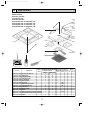
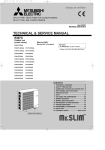
SPLIT-TYPE, HEAT PUMP AIR CONDITIONERS
SPLIT-TYPE, AIR CONDITIONERS
No.OC297
REVISED EDITION-E
TECHNICAL & SERVICE MANUAL
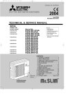
Indoor unit
[Model names]
[Service Ref.]
PLA-RP1.6AA.UK
PLA-RP2AA.UK
PLA-RP2.5AA.UK
PLA-RP3AA.UK
PLA-RP3AA1.UK
PLA-RP4AA.UK
PLA-RP4AA1.UK
PLA-RP5AA.UK
PLA-RP5AA1.UK
PLA-RP6AA.UK
PLA-RP6AA1.UK
PLA-RP1.6AA
PLA-RP2AA
PLA-RP2.5AA
PLA-RP3AA
PLA-RP4AA
PLA-RP5AA
PLA-RP6AA
Revision:
• “12. PARTS LIST” has been
modified.
Note:
• This manual does not cover
outdoor units. When serving
them, please refer to the service
manual No.OC294 REVISED
EDITION-D, OC261REVISED
EDITION-D and this manual in a
set.
• Please void OC297 REVISED
EDITION-D.
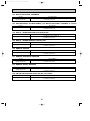
CONTENTS
Model name
indication
INDOOR UNIT
CHECK TEST RUN
MODEL SELECT
˚C
AMPM
AMPM
NOT AVAILABLE
ON/OFF
CENTRALLY CONTROLLED
TEMP
ON
1Hr.
OFF
˚C
CLOCK
CHECK
˚C
STAND BY
DEFROST
ERROR CODE
TEMP.
WIRELESS REMOTE
CONTROLLER
NOT AVAILABLE
FILTER
CHECK MODE
TEST RUN
FUNCTION
ON/OFF
WIRED REMOTE
CONTROLLER
1. TECHNICAL CHANGES ······························2
2. COMBINATION OF INDOOR AND OUTDOOR UNITS···3
3. SAFETY PRECAUTION ·······························4
4. PART NAMES AND FUNCTIONS ···············8
5. SPECIFICATIONS ······································11
6. DATA ··························································21
7. OUTLINES AND DIMENSIONS ·················60
8. WIRING DIAGRAM ····································61
9. REFRIGERANT SYSTEM DIAGRAM········62
10. TROUBLESHOOTING ·······························63
11. DISASSEMBLY PROCEDURE ··················74
12. PARTS LIST ···············································77
13. OPTIONAL PARTS ····································84
OC297-E-1.qxp
05.5.6 5:29 PM
Page 2
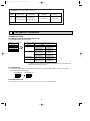
Revision:
“ 12. PARTS LIST ” has been modified on page 82.
Page
82
1
Revise point
Service Ref.
FUNCTIONAL PARTS PLA-RP4AA.UK
PLA-RP4AA1.UK
No.14 CAPACITOR
Incorrect
Correct
S70 E02 225
S70 E02 255
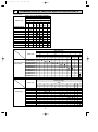
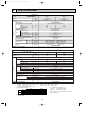
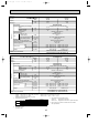
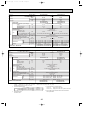
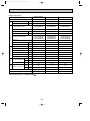
TECHNICAL CHANGES
REVISED EDITION-A
PLA-RP3,4,5,6AA.UK PLA-RP3,4,5,6AA1.UK
1. Connectable outdoor unit has changed.
● OC297 (PLA-RP•AA.UK)
OC294
R410A
PUHZ-RP3VHA
PUHZ-RP4VHA
PUHZ-RP5VHA
PUHZ-RP6VHA
● OC297 REVISED EDITION-A (PLA-RP•AA.UK, AA1.UK)
OC294
OC261 REVISED EDITION-A
R407C
R410A
PUHZ-RP3VHA PUH-P3VGAA.UK
PU-P3VGAA.UK
PU-P3VGAA1.UK
PUH-P3VGAA1.UK
PUH-P3YGAA.UK
PU-P3YGAA.UK
PUH-P3YGAA1.UK
PU-P3YGAA1.UK
PU-P4VGAA.UK
PUHZ-RP4VHA PUH-P4VGAA.UK
PUH-P4VGAA1.UK
PU-P4VGAA1.UK
PUH-P4YGAA.UK
PU-P4YGAA.UK
PUH-P4YGAA1.UK
PU-P4YGAA1.UK
PUHZ-RP5VHA PUH-P5YGAA.UK W PU-P5YGAA.UK W
PUH-P5YGAA1.UK W PU-P5YGAA1.UK W
PU-P6YGAA.UK
PUHZ-RP6VHA PUH-P6YGAA.UK
PUH-P6YGAA1.UK
PU-P6YGAA1.UK
W Note: PLA-RP5AA.UK is connected to PUHZ-RP5VHA only.
PLA-RP5AA1.UK can connect to PUHZ-RP5VHA, PUH-P5YGAA.UK, PUH-P5YGAA1.UK,
PU-P5YGAA.UK and PU-P5YGAA1.UK.
PLA-RP5AA1.UK
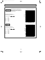
2. Corresponding to the addition of connectable outdoor unit, the setting of SW2 (Capacity setting) on the indoor
controller board have also changed.
PLA-RP5AA.UK
PLA-RP5AA1.UK
1 2 3 4
1 2 3 4
ON
OFF
ON
OFF
REVISED EDITION-B
• PLA-RP1.6AA.UK, PLA-RP2AA.UK and PLA-RP2.5AA.UK are added in REVISED EDITION-B.
2
OC297-E-1.qxp
05.5.6 5:29 PM
2
Page 3
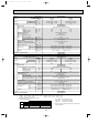
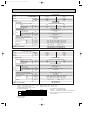
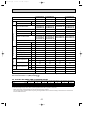
COMBINATION OF INDOOR AND OUTDOOR UNITS
(R410A Inverter)
Indoor unit
PLA-RP1.6AA.UK
PLA-RP2AA.UK
PLA-RP2.5AA.UK
PLA-RP3AA.UK
PLA-RP3AA1.UK
PLA-RP4AA.UK
PLA-RP4AA1.UK
PLA-RP5AA.UK
PLA-RP5AA1.UK
PLA-RP6AA.UK
PLA-RP6AA1.UK
Outdoor unit [OC294 REVISED EDITION-C]
Heat pump type
PUHZ-RP
4
5
1.6
2
2.5
3
6
VHA VHA VHA VHA VHA VHA VHA
VHA1 VHA1 VHA1 VHA1 VHA1
—
—
—
—
—
—
—
—
—
—
—
—
—
—
—
—
—
—
—
—
—
—
—
—
—
—
—
—
—
—
—
—
—
—
—
—
—
—
—
—
—
—
—
—
—
—
—
—
—
—
—
—
—
—
—
—
—
—
—
—
—
—
—
—
—
—
(R407C Fixed speed)
Outdoor unit [OC261 REVISED EDITION-B]
Heat pump type
PUH-P
Indoor unit
1.6
2
2.5
3
5
4
6
VGAA.UK YGAA.UK VGAA.UK YGAA.UK VGAA.UK YGAA.UK VGAA.UK YGAA.UK VGAA.UK YGAA.UK YGAA.UK YGAA.UK
VGAA1.UK YGAA1.UK VGAA1.UK YGAA1.UK VGAA1.UK YGAA1.UK VGAA1.UK YGAA1.UK VGAA1.UK YGAA1.UK YGAA1.UK YGAA1.UK
PLA-RP1.6AA.UK
PLA-RP2AA.UK
Heat pump without PLA-RP2.5AA.UK
electric heater
PLA-RP3AA.UK
PLA-RP3AA1.UK
PLA-RP4AA.UK
PLA-RP4AA1.UK
PLA-RP5AA.UK
PLA-RP5AA1.UK
PLA-RP6AA.UK
PLA-RP6AA1.UK
—
—
—
—
—
—
—
—
—
—
—
—
—
—
—
—
—
—
—
—
—
—
—
—
—
—
—
—
—
—
—
—
—
—
—
—
—
—
—
—
—
—
—
—
—
—
—
—
—
—
—
—
—
—
—
—
—
—
—
—
—
—
—
—
—
—
—
—
—
—
—
—
—
—
—
—
—
—
—
—
✕
—
—
—
—
—
—
—
—
—
—
—
—
—
—
—
—
—
—
—
—
—
—
—
—
—
—
—
—
—
—
—
—
—
—
Outdoor unit [OC261 REVISED EDITION-B]
Cooling only type
PU-P
Indoor unit
1.6
2
2.5
3
5
4
6
VGAA.UK YGAA.UK VGAA.UK YGAA.UK VGAA.UK YGAA.UK VGAA.UK YGAA.UK VGAA.UK YGAA.UK YGAA.UK YGAA.UK
Cooling only
PLA-RP1.6AA.UK
PLA-RP2AA.UK
PLA-RP2.5AA.UK
PLA-RP3AA.UK
PLA-RP3AA1.UK
PLA-RP4AA.UK
PLA-RP4AA1.UK
PLA-RP5AA.UK
PLA-RP5AA1.UK
PLA-RP6AA.UK
PLA-RP6AA1.UK
VGAA1.UK YGAA1.UK VGAA1.UK YGAA1.UK VGAA1.UK YGAA1.UK VGAA1.UK YGAA1.UK VGAA1.UK YGAA1.UK YGAA1.UK YGAA1.UK
—
—
—
—
—
—
—
—
—
—
—
—
—
—
—
—
—
—
—
—
—
—
—
—
—
—
—
—
—
—
—
—
—
—
—
—
—
—
—
—
—
—
—
—
—
—
—
—
—
—
—
—
—
—
—
—
—
—
—
—
—
—
—
—
—
—
—
—
—
—
—
—
✕
—
—
—
—
—
—
—
—
—
—
—
—
—
—
—
—
—
—
—
—
—
—
—
—
—
—
—
—
—
—
—
—
—
—
—
—
—
—
—
—
—
3
—
OC297-E-1.qxp
3
05.5.6 5:29 PM
Page 4
SAFETY PRECAUTION
CAUTIONS RELATED TO NEW REFRIGERANT
Cautions for units utilizing refrigerant R407C
Do not use the existing refrigerant piping.
Use liquid refrigerant to charge the system.
The old refrigerant and lubricant in the existing piping
contains a large amount of chlorine which may cause the
lubricant deterioration of the new unit.
If gas refrigerant is used to seal the system, the composition
of the refrigerant in the cylinder will change and performance
may drop.
Use “low residual oil piping”
Do not use a refrigerant other than R407C.
If there is a large amount of residual oil (hydraulic oil, etc.)
inside the piping and joints, deterioration of the lubricant
will result.
If another refrigerant (R22, etc.) is used, the chlorine in the
refrigerant may cause the lubricant deterioration.
Store the piping to be used during installation
indoors with keep both ends sealed until just
before brazing.
(Store elbows and other joints in a plastic bag.)
If dust, dirt, or water enters the refrigerant cycle,
deterioration of the oil and compressor trouble may result.
Use a vacuum pump with a reverse flow check valve.
The vacuum pump oil may flow back into the refrigerant
cycle and cause the lubricant deterioration.
Ventilate the room if refrigerant leaks during
operation. If refrigerant comes into contact with
a flame, poisonous gases will be released.
Use ESTR , ETHER or HAB as the lubricant to
coat flares and flange connection parts.
If large amount of mineral oil enter, that can cause
deterioration of refrigerant oil etc.
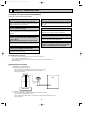
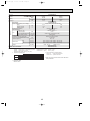
[1] Cautions for service
·After recovering the all refrigerant in the unit, proceed to working.
·Do not release refrigerant in the air.
·After completing the repair service, recharge the cycle with the specified amount of
liquid refrigerant.
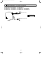
[2] Refrigerant recharging
(1) Refrigerant recharging process
1Direct charging from the cylinder.
·R407C cylinder are available on the market has a syphon pipe.
·Leave the syphon pipe cylinder standing and recharge it.
(By liquid refrigerant)
Unit
Gravimeter
(2) Recharge in refrigerant leakage case
·After recovering the all refrigerant in the unit, proceed to working.
·Do not release the refrigerant in the air.
·After completing the repair service, recharge the cycle with the specified amount of
liquid refrigerant.
4
OC297-E-1.qxp
05.5.6 5:29 PM
Page 5
[3] Service tools
Use the below service tools as exclusive tools for R407C refrigerant.
No.
1
Tool name
Specifications
Gauge manifold
·Only for R407C.
·Use the existing fitting SPECIFICATIONS. (UNF7/16)
·Use high-tension side pressure of 3.43MPa·G or over.
2
Charge hose
3
Electronic scale
4
Gas leak detector
·Use the detector for R134a or R407C.
5
Adapter for reverse flow check.
·Attach on vacuum pump.
6
Refrigerant charge base.
7
Refrigerant cylinder.
·Only for R407C.
·Use pressure performance of 5.10MPa·G or over.
·For R407C
·Top of cylinder (Brown)
·Cylinder with syphon
8
Refrigerant recovery equipment.
5
OC297-E-1.qxp
05.5.6 5:29 PM
Page 6
CAUTIONS RELATED TO NEW REFRIGERANT
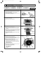
Cautions for units utilising refrigerant R410A
Use new refrigerant pipes.
Do not use refrigerant other than R410A.
In case of using the existing pipes for R22, be careful with
the followings.
· For RP4, 5 and 6, be sure to perform replacement operation before test run.
· Change flare nut to the one provided with this product.
Use a newly flared pipe.
· Avoid using thin pipes.
If other refrigerant (R22 etc.) is used, chlorine in refrigerant can cause deterioration of refrigerant oil etc.
Make sure that the inside and outside of refrigerant piping is clean and it has no contamination
such as sulfur hazardous for use, oxides, dirt,
shaving particles, etc.
In addition, use pipes with specified thickness.
Use a vacuum pump with a reverse flow check
valve.
Vacuum pump oil may flow back into refrigerant cycle and
that can cause deterioration of refrigerant oil etc.
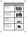
Use the following tools specifically designed for
use with R410A refrigerant.
The following tools are necessary to use R410A refrigerant.
Gauge manifold
Charge hose
Gas leak detector
Torque wrench
Contamination inside refrigerant piping can cause deterioration of refrigerant oil etc.
Tools for R410A
Flare tool
Size adjustment gauge
Vacuum pump adaptor
Electronic refrigerant
charging scale
Store the piping to be used during installation
indoors and keep both ends of the piping sealed
until just before brazing. (Leave elbow joints, etc.
in their packaging.)
Keep the tools with care.
If dirt, dust or moisture enter into refrigerant cycle, that can
cause deterioration of refrigerant oil or malfunction of compressor.
If dirt, dust or moisture enter into refrigerant cycle, that can
cause deterioration of refrigerant oil or malfunction of compressor.
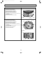
Use ester oil, ether oil or alkylbenzene oil (small
amount) as the refrigerant oil applied to flares
and flange connections.
If large amount of mineral oil enter, that can cause deterioration of refrigerant oil etc.
Charge refrigerant from liquid phase of gas
cylinder.
Do not use a charging cylinder.
If a charging cylinder is used, the composition of refrigerant will change and the efficiency will be lowered.
Ventilate the room if refrigerant leaks during
operation. If refrigerant comes into contact with
a flame, poisonous gases will be released.
If the refrigerant is charged from gas phase, composition
change may occur in refrigerant and the efficiency will be
lowered.
[1] Cautions for service
(1) Perform service after collecting the refrigerant left in unit completely.
(2) Do not release refrigerant in the air.
(3) After completing service, charge the cycle with specified amount of refrigerant.
(4) When performing service, install a filter drier simultaneously.
Be sure to use a filter drier for new refrigerant.
[2] Additional refrigerant charge
When charging directly from cylinder
· Check that cylinder for R410A on the market is syphon type.
· Charging should be performed with the cylinder of syphon stood vertically. (Refrigerant is charged from liquid phase.)
6
OC297-E-1.qxp
05.5.6 5:29 PM
Page 7
Unit
Gravimeter
[3] Service tools
Use the below service tools as exclusive tools for R410A refrigerant.
No.
1
Specifications
Gauge manifold
·Only for R410A
·Use the existing fitting specifications. (UNF1/2)
·Use high-tension side pressure of 5.3MPa·G or over.
2
Charge hose
3
Electronic scale
4
Gas leak detector
·Use the detector for R134a, R407C or R410A.
5
Adaptor for reverse flow check
·Attach on vacuum pump.
6
Refrigerant charge base
7
Refrigerant cylinder
8
Refrigerant recovery equipment
·Only for R410A
·Use pressure performance of 5.09MPa·G or over.
·Only for R410A
Top of cylinder (Pink)
Cylinder with syphon
7
OC297-E-1.qxp
4
05.5.6 5:29 PM
Page 8
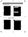
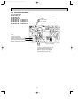
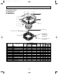
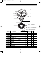
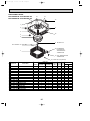
PART NAMES AND FUNCTIONS
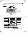
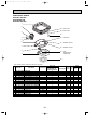
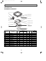
● Indoor Unit
Filter
Removes dust and pollutants
from intake air
Horizontal Air Outlet
Sets airflow of horizontal automatically
during cooling or dehumidifying.
Grille
Auto Air Swing Vane
Disperses airflow up and
down and adjusts the angle
of airflow direction.
Air Intake
Intakes air from room.
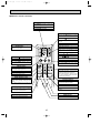
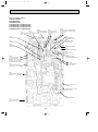
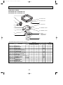
● Wired remote controller
On the controls are set, the same operation mode can be repeated by simply pressing the ON/OFF button.
● Operation buttons
TEMP. ADJUSTMENT button
This sets the room temperature. The
temperature setting can be performed
in 1: units
Setting range
Cooling 19: to 30:
Heating 17: to 28:
TIME SETTING button
FAN SPEED button
This sets the current time, start time
and stop time.
This sets the ventilation fan speed.
ON/OFF button
This switches between the operation
and stop modes each time it is pressed.
The lamp on this button lights during
operation.
TIMER button
1Hr.
CENTRALLY CONTROLLED
ON
This switches between continuous
operation and the timer operation.
OFF
˚C
CLOCK
CHECK
˚C
STAND BY
DEFROST
ERROR CODE
NOT AVAILABLE
TEMP.
FILTER
CHECK MODE
TEST RUN
FUNCTION
ON/OFF
AIR DIRECTION button
This adjusts the vertical angle of the
ventilation.
FILTER
OPERATION SWITCH button
Press this button to switch between
cool, dry, automatic and heat modes.
CHECK TEST
PAR-20MAA
FILTER button
TIMER SET
This resets the filter service indication
display
LOUVER button
VENTILATION button
CHECK-TEST RUN button
To switch the horizontal fan motion
ON and OFF.
This sets the ventilation fan speed.
Only press this button to perform an
inspection check or test operation.
Do not use it for normal operation.
(Not available for this model.)
8
OC297-E-1.qxp
05.5.6 5:29 PM
Page 9
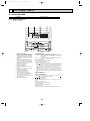
● Display
CENTRALLY
CONTROLLED display
This indicates when the unit is controlled by optional features such as
central control type remote controller.
In this display example on the bottom left, a condition where all display lamps light is shown for explanation purposes although this differs
from actual operation.
CLOCK display
The current time , start time and stop
time can be displayed in ten second
intervals by pressing the time switch
button. The start time or stop time is
always displayed during the timer
operation.
AIR DIRECTION display
TIMER display
This displays the air direction.
This indicates when the continuous
operation and time operation modes
are set.
It also display the time for the timer
operation at the same time as when
it is set.
AIR SPEED display
The selected fan speed is displayed.
ROOM TEMPERATURE
1Hr.
CENTRALLY CONTROLLED
OPERATION MODE display
This indicates the operation mode.
ON
OFF
˚C
CLOCK
CHECK
˚C
STAND BY
DEFROST
ERROR CODE
TEMP.
NOT AVAILABLE
FILTER
CHECK MODE
TEST RUN
FUNCTION
ON/OFF
display
The temperature of the suction air
is displayed during operation. The
display range is 8°C to 39°C. The
display flashes 8°C when the actual
temperature is less than 8°C and
flashes 39°C when the actual temperature is greater than 39°C.
FILTER
STANDBY display
The [STANDBY] symbol is only displayed from the time the heating
operation starts until the heated air
begins to blow.
CHECK TEST
PAR-20MAA
TIMER SET
Operation lamp
This lamp lights during operation,
goes off when the unit stops and
flashes when a malfunction occurs.
CHECK MODE
TEST RUN
DEFROST display
display
This display lights in the check mode
or when a test operation is performed.
This indicates when the defrost operation is performed.
FILTER display
This lamp lights when the filter need
to be cleaned.
CHECK display
This indicates when a malfunction
has occurred in the unit which should
be checked.
SET TEMPERATURE display
POWER display
This displays the selected setting
temperature.
This lamp lights when electricity is
supplied to the unit.
Caution
● Only the Power display lights when the unit is stopped and power supplied to the unit.
● When the central control remote control unit, which is sold separately, is used the ON-OFF button, operation switch button
and
TEMP. adjustment button do not operate.
● “NOT AVAILABLE” is displayed when the Air speed button is pressed. This indicates that this room unit is not equipped with
the fan direction adjustment function and the louver function.
● When power is turned ON for the first time, it is normal that “H0” is displayed on the room temperature indication (For max.
2minutes). Please wait until this “H0” indication disappear then start the operation.
9
OC297-E-1.qxp
05.5.6 5:29 PM
Page 10
● Wireless remote controller
CHECK TEST RUN display
CHECK&TEST RUN display indicates that
the unit is being checked or test-run.
MODEL SELECT display
Blinks when model is selected.
display
Lights up while transmission to the indoor
unit is mode using switches.
display
SET TEMP. display indicates desired temperature set.
CLOCK display
display
Displays the current time.
OPERATION MODE display
Operation mode display indicates which operation mode is in effect.
TIMER display
CHECK TEST RUN
MODEL SELECT
˚C
AMPM
Displays when in timer operation or when
setting timer.
“
AMPM
NOT AVAILABLE
display
The vertical direction of air flow is indicated.
ON/OFF
“
TEMP
”“
” display
Displays the order of timer operation.
”“
” display
Displays whether timer is on or off.
display
button
FAN SPEED display indicates which fan
speed has been selected.
FAN
AUTO STOP
VANE
AUTO START
SET TEMPERATURE button sets any desired
room temperature.
ON/OFF button
The unit is turned ON and OFF alternately
each time the button is pressed.
MODE
CHECK LOUVER
h
FAN SPEED SELECT button
Used to change the fan speed.
MODE SELECT button
TEST RUN
SET
min
RESET
TIMER CONTROL buttons
AUTO STOP (OFF timer): when this switch
is set, the air conditioner will be automatically stopped at the preset time.
AUTO START (ON timer): when this switch
is set, the air conditioner will be automatically started at the preset time.
CLOCK
Used to switch the operation mode between
cooling, drying, blowing, heating and auto
mode.
h and min buttons
Buttons used to set the “hour and minute” of
the current time and timer settings.
w In case the outdoor unit is cool only type,
the heating mode is not available.
LOUVER button
CHECK-TEST RUN button
This switch the horizontal fan motion ON
and OFF.
Only press this button to perform an inspection check or test operation.
Do not use it for normal operation.
(Not available for this model.)
CLOCK button
VANE CONTROL button
RESET button
Used to change the air flow direction.
SET button
10
OC297-E-1.qxp
05.5.6 5:29 PM
5
Page 11
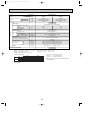
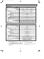
SPECIFICATIONS
Heat pump type (1)
Service Ref.
Item
Function
Btu/h
W
kW
Capacity
Total input
PLA-RP1.6AA.UK
Cooling
12,300
3,600(1,600~4,500)
1.07
PLA-RP1.6AA.UK
Indoor unit
Service Ref.
Single phase, 50Hz, 220-230-240V
0.16
0.16
0.79
0.79
1.0
1.0
Munsell 0.70Y 8.59/0.97
Plate fin coil
Turbo fan (direct) o1
0.070
11-12-13-14(390-425-460-495)
0 (direct blow)
—
Remote controller & built-in
27-28-29-31
32 (1-1/4)
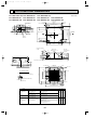
UNIT : 840 (33-1/16)
PANEL : 950 (37-3/8)
UNIT : 840 (33-1/16)
PANEL : 950 (37-3/8)
UNIT : 258 (10-3/16)
PANEL : 30 (1-3/16)
Power supply (phase, cycle, voltage)
Input
kW
Running current
A
Starting current
A
External finish (Panel)
Heat exchanger
Fan (drive) o No.
Fan motor output
kW
Fan
Airflow (Low-Medium2-Medium1-High) K / min (CFM)
External static pressure
Pa (mmAq)
Booster heater
kW
Operation control & Thermostat
Sound level (Low-Medium2-Medium1-High)
dB
Unit drain pipe I.D.
mm (in.)
W
mm (in.)
Dimensions
D
mm (in.)
H
mm (in.)
Weight
kg (lbs.)
UNIT : 24 (53)
Service Ref.
PLA-RP2AA.UK
Cooling
17,100
5,000(2,300~5,600)
1.55
Btu/h
W
kW
Capacity
Total input
Indoor unit
Service Ref.
PLA-RP2AA.UK
UNIT : 24(53)
kg (lbs.)
Outdoor unit Service Ref.
NOTE:
Upper limit
Lower limit
Upper limit
Heating
Lower limit
PANEL : 5 (11)
PUHZ-RP2VHA
1. Rating conditions (ISO T1)
Cooling
Indoor : D.B. 27: (80˚F) W.B. 19: (66˚F)
Heating
Indoor : D.B. 20: (68˚F)
Refrigerant piping length (one way) : 5m (16ft.)
2. Guaranteed operating range
Cooling
Heating
20,500
6,000(2,500~7,300)
1.62
Single phase, 50Hz, 220-230-240V
0.16
0.16
0.79
0.79
1.0
1.0
Munsell 0.70Y 8.59/0.97
Plate fin coil
Turbo fan (direct) o1
0.070
14-15-16-18(495-530-565-635)
0 (direct blow)
—
Remote controller & built-in
28-29-31-33
32 (1-1/4)
UNIT : 840 (33-1/16) PANEL : 950 (37-3/8)
UNIT : 840 (33-1/16) PANEL : 950 (37-3/8)
UNIT : 258 (10-3/16) PANEL : 30 (1-3/16)
Power supply (phase, cycle,voltage)
Input
kW
Running current
A
Starting current
A
External finish (Panel)
Heat exchanger
Fan (drive) o No.
Fan motor output
kW
Fan
Airflow (Low-Medium2-Medium1-High) K / min (CFM)
External static pressure
Pa (mmAq)
Booster heater
kW
Operation control & Thermostat
Sound level (Low-Medium2-Medium1-High)
dB
Unit drain pipe I.D.
mm (in.)
W
mm (in.)
Dimensions
D
mm (in.)
H
mm (in.)
Weight
PANEL: 5 (11)
PUHZ-RP1.6VHA
Outdoor unit Service Ref.
Item
Function
Heating
14,000
4,100(1,600~5,200)
1.12
Outdoor : D.B. 35: (95˚F) W.B. 24: (75˚F)
Outdoor : D.B. 7: (45˚F) W.B. 6: (43˚F)
Indoor
Outdoor
D.B. 35˚C, W.B. 22.5˚C D.B. 46˚C
D.B. 19˚C, W.B. 15˚C
D.B. -5˚C
D.B. 21˚C, W.B. 15˚C
D.B. 28˚C
D.B. -11˚C, W.B. -12˚C
D.B. 17˚C
3. Guaranteed voltage
198~264V, 50Hz
11
4. Above data based on indicated voltage
Indoor unit
Single phase 230V 50Hz
Outdoor unit
Single phase 230V 50Hz
5. Refer to the service manual of outdoor unit for tha outdoor
unit's specifications.
OC297-E-1.qxp
05.5.6 5:29 PM
Page 12
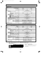
Service Ref.
Item
Function
Btu/h
W
kW
Capacity
Total input
PLA-RP2.5AA.UK
Cooling
20,500
6,000 (2,700~6,700)
1.65
Indoor unit
Service Ref.
PLA-RP2.5AA.UK
Single phase, 50Hz, 220-230-240V
0.16
0.16
0.79
0.79
1.0
1.0
Munsell 0.70Y 8.59/0.97
Plate fin coil
Turbo fan (direct) o1
0.070
14-15-16-18(495-530-565-635)
0 (direct blow)
—
Remote controller & built-in
28-29-31-33
32 (1-1/4)
UNIT : 840 (33-1/16)
PANEL : 950 (37-3/8)
UNIT : 840 (33-1/16)
PANEL : 950 (37-3/8)
UNIT : 258 (10-3/16)
PANEL : 30 (1-3/16)
Power supply (phase, cycle, voltage)
Input
kW
Running current
A
Starting current
A
External finish (Panel)
Heat exchanger
Fan (drive) o No.
Fan motor output
kW
Fan
Airflow (Low-Medium2-Medium1-High) K / min (CFM)
External static pressure
Pa (mmAq)
Booster heater
kW
Operation control & Thermostat
Sound level (Low-Medium2-Medium1-High)
dB
Unit drain pipe I.D.
mm (in.)
W
mm (in.)
Dimensions
D
mm (in.)
H
mm (in.)
Weight
kg (lbs.)
UNIT : 24 (53)
PLA-RP3AA.UK
PLA-RP3AA1.UK
Service Ref.
Btu/h
W
kW
Capacity
Total input
Cooling
24,200
7,100 (3,300~8,100)
1.97
Indoor unit
Power supply (phase, cycle, voltage)
Input
kW
Running current
A
Starting current
A
External finish (Panel)
Heat exchanger
Fan (drive) o No.
Fan motor output
kW
Fan
Airflow (Low-Medium2-Medium1-High) K / min (CFM)
External static pressure
Pa (mmAq)
Booster heater
kW
Operation control & Thermostat
Sound level (Low-Medium2-Medium1-High)
dB
Unit drain pipe I.D.
mm (in.)
W
mm (in.)
Dimensions
D
mm (in.)
H
mm (in.)
kg (lbs.)
UNIT : 24 (53)
1. Rating conditions (ISO T1)
Cooling
Indoor : D.B. 27: (80˚F) W.B. 19: (66˚F)
Heating
Indoor : D.B. 20: (68˚F)
Refrigerant piping length (one way) : 5m (16ft.)
2. Guaranteed operating range
Upper limit
Lower limit
Upper limit
Heating
Lower limit
Cooling
PANEL: 5 (11)
PUHZ-RP3VHA
PUHZ-RP3VHA1
Outdoor unit Service Ref.
NOTE:
Heating
27,300
8,000 (3,500~10,200)
2.34
PLA-RP3AA.UK
PLA-RP3AA1.UK
Single phase, 50Hz, 220-230-240V
0.16
0.16
0.79
0.79
1.0
1.0
Munsell 0.70Y 8.59/0.97
Plate fin coil
Turbo fan (direct) o1
0.070
15-16-18-20 (530-565-635-705)
0 (direct blow)
—
Remote controller & built-in
28-30-32-34
32 (1-1/4)
UNIT : 840 (33-1/16)
PANEL : 950 (37-3/8)
UNIT : 840 (33-1/16)
PANEL : 950 (37-3/8)
UNIT : 258 (10-3/16)
PANEL : 30 (1-3/16)
Service Ref.
Weight
PANEL: 5 (11)
PUHZ-RP2.5VHA
PUHZ-RP2.5VHA1
Outdoor unit Service Ref.
Item
Function
Heating
23,900
7,000 (2,800~8,200)
1.85
Outdoor : D.B. 35: (95˚F) W.B. 24: (75˚F)
Outdoor : D.B. 7: (45˚F) W.B. 6: (43˚F)
Indoor
Outdoor
D.B. 35˚C, W.B. 22.5˚C D.B. 46˚C
D.B. 19˚C, W.B. 15˚C
D.B. -5˚C
D.B. 21˚C, W.B. 15˚C
D.B. 28˚C
D.B. -11˚C, W.B. -12˚C
D.B. 17˚C
3. Guaranteed voltage
198~264V, 50Hz
12
4. Above data based on indicated voltage
Indoor unit
Single phase 230V 50Hz
Outdoor unit
Single phase 230V 50Hz
5. Refer to the service manual of outdoor unit for tha outdoor
unit's specifications.
OC297-E-1.qxp
05.5.6 5:29 PM
Page 13
Capacity
PUHZ-RP4VHA
PUHZ-RP4VHA1
Total input
Btu/h
W
W
kW
Service Ref.
Power supply (phase, cycle, voltage)
Input
kW
Running current
A
Starting current
A
External finish (Panel)
Heat exchanger
Fan (drive) o No.
Fan motor output
kW
Fan
Airflow (Low-Medium2-Medium1-High) K / min (CFM)
External static pressure
Pa (mmAq)
Booster heater
kW
Operation control & Thermostat
Sound level (Low-Medium2-Medium1-High)
dB
Unit drain pipe I.D.
mm (in.)
W
mm (in.)
Dimensions
D
mm (in.)
H
mm (in.)
Indoor unit
PLA-RP4AA.UK
PLA-RP4AA1.UK
Service Ref.
Item
Function
Weight
Cooling
Heating
34,100
38,200
10,000 (5,000~11,400)
11,200 (5,600~14,000)
10,000 (4,900~11,400)
11,200 (4,500~14,000)
3.03
3.39
PLA-RP4AA.UK
PLA-RP4AA1.UK
Single phase, 50Hz, 220-230-240V
0.25
0.25
1.25
1.25
2.0
2.0
Munsell 0.70Y 8.59/0.97
Plate fin coil
Turbo fan (direct) o1
0.120
20-23-26-28 (705-810-920-990)
0 (direct blow)
—
Remote controller & built-in
33-36-39-41
32 (1-1/4)
UNIT : 840 (33-1/16) PANEL : 950 (37-3/8)
UNIT : 840 (33-1/16) PANEL : 950 (37-3/8)
UNIT : 298 (11-3/4) PANEL : 30 (1-3/16)
UNIT : 30 (66)
kg (lbs.)
PUHZ-RP4VHA
PUHZ-RP4VHA1
Outdoor unit Service Ref.
Capacity
PUHZ-RP5VHA
PUHZ-RP5VHA1
Total input
Btu/h
W
W
kW
Service Ref.
Indoor unit
PLA-RP5AA.UK
PLA-RP5AA1.UK
Service Ref.
Item
Function
Power supply (phase, cycle, voltage)
Input
kW
Running current
A
Starting current
A
External finish (Panel)
Heat exchanger
Fan (drive) o No.
Fan motor output
kW
Fan
Airflow (Low-Medium2-Medium1-High) K / min (CFM)
External static pressure
Pa (mmAq)
Booster heater
kW
Operation control & Thermostat
Sound level (Low-Medium2-Medium1-High)
dB
Unit drain pipe I.D.
mm (in.)
W
mm (in.)
Dimensions
D
mm (in.)
H
mm (in.)
Weight
Heating
Cooling
47,800
42,700
12,500 (6,000~14,000)
14,000 (6,000~16,000)
12,500 (5,500~14,000)
14,000 (5,000~16,000)
4.27
3.89
PLA-RP5AA.UK
PLA-RP5AA1.UK
Single phase, 50Hz, 220-230-240V
0.33
0.33
1.64
1.64
2.0
2.0
Munsell 0.70Y 8.59/0.97
Plate fin coil
Turbo fan (direct) o1
0.120
22-25-28-30 (775-880-990-1,060)
0 (direct blow)
—
Remote controller & built-in
37-40-43-45
32 (1-1/4)
UNIT : 840 (33-1/16) PANEL : 950 (37-3/8)
UNIT : 840 (33-1/16) PANEL : 950 (37-3/8)
UNIT : 298 (11-3/4) PANEL : 30 (1-3/16)
kg (lbs.)
UNIT : 32 (71)
1. Rating conditions (ISO T1)
Cooling
Indoor : D.B. 27: (80˚F) W.B. 19: (66˚F)
Heating
Indoor : D.B. 20: (68˚F)
Refrigerant piping length (one way) : 5m (16ft.)
2. Guaranteed operating range
Upper limit
Lower limit
Upper limit
Heating
Lower limit
Cooling
PANEL : 5 (11)
PUHZ-RP5VHA
PUHZ-RP5VHA1
Outdoor unit Service Ref.
NOTE:
PANEL : 5 (11)
Outdoor : D.B. 35: (95˚F) W.B. 24: (75˚F)
Outdoor : D.B. 7: (45˚F) W.B. 6: (43˚F)
Indoor
Outdoor
D.B. 35˚C, W.B. 22.5˚C D.B. 46˚C
D.B. 19˚C, W.B. 15˚C
D.B. -5˚C
D.B. 21˚C, W.B. 15˚C
D.B. 28˚C
D.B. -11˚C, W.B. -12˚C
D.B. 17˚C
3. Guaranteed voltage
198~264V, 50Hz
13
4. Above data based on indicated voltage
Indoor unit
Single phase 230V 50Hz
Outdoor unit
Single phase 230V 50Hz
5. Refer to the service manual of outdoor unit for tha outdoor
unit's specifications.
OC297-E-1.qxp
05.5.6 5:29 PM
Page 14
PLA-RP6AA.UK
PLA-RP6AA1.UK
Service Ref.
Item
Function
Capacity
PUHZ-RP6VHA
PUHZ-RP6VHA1
Total input
Btu/h
W
W
kW
Cooling
47,800
14,000 (6,200~15,300)
14,000 (5,500~15,300)
4.99
Heating
54,600
16,000 (6,200~18,000)
16,000 (5,000~18,000)
4.91
PLA-RP6AA.UK
PLA-RP6AA1.UK
Single phase, 50Hz, 220-230-240V
0.33
0.33
1.64
1.64
2.0
2.0
Munsell 0.70Y 8.59/0.97
Plate fin coil
Turbo fan (direct) o1
0.120
22-25-28-30 (775-880-990-1,060)
0 (direct blow)
—
Remote controller & built-in
37-40-43-45
32 (1-1/4)
UNIT : 840 (33-1/16) PANEL : 950 (37-3/8)
UNIT : 840 (33-1/16) PANEL : 950 (37-3/8)
UNIT : 298 (11-3/4) PANEL : 30 (1-3/16)
Indoor unit
Service Ref.
Power supply (phase, cycle, voltage)
Input
kW
Running current
A
Starting current
A
External finish (Panel)
Heat exchanger
Fan (drive) o No.
Fan motor output
kW
Fan
Airflow (Low-Medium2-Medium1-High) K / min (CFM)
External static pressure
Pa (mmAq)
Booster heater
kW
Operation control & Thermostat
Sound level (Low-Medium2-Medium1-High)
dB
Unit drain pipe I.D.
mm (in.)
W
mm (in.)
Dimensions
D
mm (in.)
H
mm (in.)
Weight
kg (lbs.)
UNIT : 32 (71)
PUHZ-RP6VHA
PUHZ-RP6VHA1
Outdoor unit Service Ref.
NOTE:
1. Rating conditions (ISO T1)
Cooling : Indoor: D.B. 27: (80˚F) W.B. 19: (66˚F)
Heating : Indoor: D.B. 20: (68˚F)
Refrigerant piping length (one way) : 5m (16ft.)
2. Guaranteed operating range
Upper limit
Lower limit
Upper limit
Heating
Lower limit
Cooling
PANEL : 5 (11)
Indoor
D.B. 35:, W.B. 22.5:
D.B. 19 :, W.B. 15:
D.B. 28:
D.B. 17:
Outdoor: D.B. 35: (95˚F)
Outdoor: D.B. 7: (45˚F)
Outdoor
D.B. 46:
D.B. -5:
D.B. 21:, W.B. 15:
D.B. -11:, W.B. -12:
3. Guaranteed voltage
198~264V, 50Hz
14
W.B. 24: (75˚F)
W.B. 6: (43˚F)
4. Above data based on indicated voltage
Indoor unit
Single phase 230V 50Hz
Outdoor unit
Single phase 230V 50Hz
5. Refer to the service manual of outdoor unit for tha outdoor
unit's specifications.
OC297-E-1.qxp
05.5.6 5:29 PM
Page 15
Heat pump type (2)
Service Ref.
Item
Function
Capacity
Total input
PLA-RP1.6AA.UK
Cooling
15,400
4,500
1.72
Btu/h
W
kW
PLA-RP1.6AA.UK
Indoor unit
Service Ref.
Power supply (phase, cycle, voltage)
Input
kW
Running current
A
Starting current
A
External finish (Panel)
Heat exchanger
Fan (drive) o No.
Fan motor output
kW
Fan
Airflow (Low-Medium2-Medium1-High) K / min (CFM)
External static pressure
Pa (mmAq)
Booster heater
kW
Operation control & Thermostat
Sound level (Low-Medium2-Medium1-High)
dB
Unit drain pipe I.D.
mm (in.)
W
mm (in.)
Dimensions
D
mm (in.)
H
mm (in.)
Weight
Single phase, 50Hz, 220-230-240V
0.16
0.79
1.0
Munsell 0.70Y 8.59/0.97
Plate fin coil
Turbo fan (direct) o 1
0.070
11-12-13-14(390-425-460-495)
0 (direct blow)
—
Remote controller & built-in
27-28-29-31
32 (1-1/4)
UNIT : 840 (33-1/16)
PANEL : 950 (37-3/8)
UNIT : 840 (33-1/16)
PANEL : 950 (37-3/8)
UNIT : 258 (10-3/16)
PANEL : 30 (1-3/16)
0.16
0.79
1.0
kg (lbs.)
UNIT : 24 (53)
Service Ref.
Capacity
Total input
PLA-RP2AA.UK
Cooling
19,100
5,600
2.53
Btu/h
W
kW
Indoor unit
Service Ref.
PLA-RP2AA.UK
kg (lbs.)
UNIT : 24 (53)
PANEL : 5 (11)
PUH-P2VGAA.UK / PUH-P2YGAA.UK
PUH-P2VGAA1.UK / PUH-P2YGAA1.UK
Outdoor unit Service Ref.
NOTE:
Heating
21,700
6,350
2.20
Single phase, 50Hz, 220-230-240V
0.16
0.16
0.79
0.79
1.0
1.0
Munsell 0.70Y 8.59/0.97
Plate fin coil
Turbo fan (direct) o 1
0.070
14-15-16-18(495-530-565-635)
0 (direct blow)
—
Remote controller & built-in
28-29-31-33
32 (1-1/4)
UNIT : 840 (33-1/16) PANEL : 950 (37-3/8)
UNIT : 840 (33-1/16) PANEL : 950 (37-3/8)
UNIT : 258 (10-3/16) PANEL : 30 (1-3/16)
Power supply (phase, cycle,voltage)
Input
kW
Running current
A
Starting current
A
External finish (Panel)
Heat exchanger
Fan (drive) o No.
Fan motor output
kW
Fan
Airflow (Low-Medium2-Medium1-High) K / min (CFM)
External static pressure
Pa (mmAq)
Booster heater
kW
Operation control & Thermostat
Sound level (Low-Medium2-Medium1-High)
dB
Unit drain pipe I.D.
mm (in.)
W
mm (in.)
Dimensions
D
mm (in.)
H
mm (in.)
Weight
PANEL: 5 (11)
PUH-P1.6VGAA.UK / PUH-P1.6YGAA.UK
PUH-P1.6VGAA1.UK / PUH-P1.6YGAA1.UK
Outdoor unit Service Ref.
Item
Function
Heating
16,900
4,950
1.70
1. Rating conditions (ISO T1)
Cooling
Indoor : D.B. 27: (80˚F) W.B. 19: (66˚F)
Outdoor : D.B. 35: (95˚F) W.B. 24: (75˚F)
Heating
Indoor : D.B. 20: (68˚F)
Outdoor : D.B. 7: (45˚F) W.B. 6: (43˚F)
Refrigerant piping length (one way) : 5m (16ft.)
2. Guaranteed operating range
4. Above data based on indicated voltage
Indoor unit
Single phase 230V 50Hz
Indoor
Outdoor
Outdoor unit
Single phase 230V 50Hz / 3 phase 400V 50Hz
Upper limit D.B. 35˚C, W.B. 22.5˚C D.B. 46˚C
Cooling
Lower limit D.B. 19˚C, W.B. 15˚C
D.B. -5˚C
Upper limit D.B. 28˚C
D.B. 24˚C, W.B. 18˚C
5. Refer to the service manual of outdoor unit for tha outdoor
Heating
unit's specifications.
Lower limit D.B. 17˚C
D.B. -11˚C, W.B. -12˚C
3. Guaranteed voltage
198~264V, 50Hz
15
OC297-E-1.qxp
05.5.6 5:29 PM
Page 16
Service Ref.
Item
Function
Capacity
Total input
Btu/h
W
kW
PLA-RP2.5AA.UK
Cooling
22,900
6,700
2.57
Indoor unit
Service Ref.
PLA-RP2.5AA.UK
Power supply (phase, cycle, voltage)
Input
kW
Running current
A
Starting current
A
External finish (Panel)
Heat exchanger
Fan (drive) o No.
Fan motor output
kW
Fan
Airflow (Low-Medium2-Medium1-High) K / min (CFM)
External static pressure
Pa (mmAq)
Booster heater
kW
Operation control & Thermostat
Sound level (Low-Medium2-Medium1-High)
dB
Unit drain pipe I.D.
mm (in.)
W
mm (in.)
Dimensions
D
mm (in.)
H
mm (in.)
Weight
UNIT : 24 (53)
Total input
Btu/h
W
kW
Service Ref.
Power supply (phase, cycle, voltage)
Input
kW
Running current
A
Starting current
A
External finish (Panel)
Heat exchanger
Fan (drive) o No.
Fan motor output
kW
Fan
Airflow (Low-Medium2-Medium1-High) K / min (CFM)
External static pressure
Pa (mmAq)
Booster heater
kW
Operation control & Thermostat
Sound level (Low-Medium2-Medium1-High)
dB
Unit drain pipe I.D.
mm (in.)
W
mm (in.)
Dimensions
D
mm (in.)
H
mm (in.)
Weight
PLA-RP3AA.UK
PLA-RP3AA1.UK
Cooling
26,300
7,700
3.42
Heating
31,400
9,200
3.48
PLA-RP3AA.UK
PLA-RP3AA1.UK
Single phase, 50Hz, 220-230-240V
0.16
0.16
0.79
079
1.0
1.0
Munsell 0.70Y 8.59/0.97
Plate fin coil
Turbo fan (direct) o 1
0.070
15-16-18-20 (530-565-635-705)
0 (direct blow)
—
Remote controller & built-in
28-30-32-34
32 (1-1/4)
UNIT : 840 (33-1/16)
PANEL : 950 (37-3/8)
UNIT : 840 (33-1/16)
PANEL : 950 (37-3/8)
UNIT : 258 (10-3/16)
PANEL : 30 (1-3/16)
kg (lbs.)
UNIT : 24 (53)
PANEL: 5 (11)
PUH-P3VGAA.UK / PUH-P3YGAA.UK
PUH-P3VGAA1.UK / PUH-P3YGAA1.UK
Outdoor unit Service Ref.
NOTE:
PANEL: 5 (11)
PUH-P2.5VGAA.UK / PUH-P2.5YGAA.UK
PUH-P2.5VGAA1.UK / PUH-P2.5YGAA1.UK
Service Ref.
Capacity
Indoor unit
Single phase, 50Hz, 220-230-240V
0.16
0.79
1.0
Munsell 0.70Y 8.59/0.97
Plate fin coil
Turbo fan (direct) o 1
0.070
14-15-16-18(495-530-565-635)
0 (direct blow)
—
Remote controller & built-in
28-29-31-33
32 (1-1/4)
UNIT : 840 (33-1/16)
PANEL : 950 (37-3/8)
UNIT : 840 (33-1/16)
PANEL : 950 (37-3/8)
UNIT : 258 (10-3/16)
PANEL : 30 (1-3/16)
0.16
0.79
1.0
kg (lbs.)
Outdoor unit Service Ref.
Item
Function
Heating
24,900
7,300
2.40
1. Rating conditions (ISO T1)
Cooling
Indoor : D.B. 27: (80˚F) W.B. 19: (66˚F)
Outdoor : D.B. 35: (95˚F) W.B. 24: (75˚F)
Heating
Indoor : D.B. 20: (68˚F)
Outdoor : D.B. 7: (45˚F) W.B. 6: (43˚F)
Refrigerant piping length (one way) : 5m (16ft.)
2. Guaranteed operating range
4. Above data based on indicated voltage
Indoor unit
Single phase 230V 50Hz
Indoor
Outdoor
Outdoor unit
Single phase 230V 50Hz / 3 phase 400V 50Hz
Upper limit D.B. 35˚C, W.B. 22.5˚C D.B. 46˚C
Cooling
Lower limit D.B. 19˚C, W.B. 15˚C
D.B. -5˚C
Upper limit D.B. 28˚C
D.B. 24˚C, W.B. 18˚C
5. Refer to the service manual of outdoor unit for tha outdoor
Heating
unit's specifications.
Lower limit D.B. 17˚C
D.B. -11˚C, W.B. -12˚C
3. Guaranteed voltage
198~264V, 50Hz
16
OC297-E-1.qxp
05.5.6 5:29 PM
Page 17
PLA-RP4AA.UK
PLA-RP4AA1.UK
Service Ref.
Item
Function
Capacity
Total input
Cooling
32,800
9,600
3.68
Btu/h
W
kW
PLA-RP4AA.UK
PLA-RP4AA1.UK
Single phase, 50Hz, 220-230-240V
0.25
0.25
1.25
1.25
2.0
2.0
Munsell 0.70Y 8.59/0.97
Plate fin coil
Turbo fan (direct) o 1
0.120
20-23-26-28 (705-810-920-990)
0 (direct blow)
—
Remote controller & built-in
33-36-39-41
32 (1-1/4)
UNIT : 840 (33-1/16) PANEL : 950 (37-3/8)
UNIT : 840 (33-1/16) PANEL : 950 (37-3/8)
UNIT : 298 (11-3/4) PANEL : 30 (1-3/16)
Indoor unit
Service Ref.
Power supply (phase, cycle,voltage)
Input
kW
Running current
A
Starting current
A
External finish (Panel)
Heat exchanger
Fan (drive) o No.
Fan motor output
kW
Fan
Airflow (Low-Medium2-Medium1-High) K / min (CFM)
External static pressure
Pa (mmAq)
Booster heater
kW
Operation control & Thermostat
Sound level (Low-Medium2-Medium1-High)
dB
Unit drain pipe I.D.
mm (in.)
W
mm (in.)
Dimensions
D
mm (in.)
H
mm (in.)
Weight
UNIT : 30 (66)
kg (lbs.)
Service Ref.
Capacity
Total input
PLA-RP5AA1.UK
Cooling
45,400
13,300
5.09
Btu/h
W
kW
Indoor unit
Service Ref.
Single phase, 50Hz, 220-230-240V
0.33
0.33
1.64
1.64
2.0
2.0
Munsell 0.70Y 8.59/0.97
Plate fin coil
Turbo fan (direct) o 1
0.120
22-25-28-30 (775-880-990-1,060)
0 (direct blow)
—
Remote controller & built-in
37-40-43-45
32 (1-1/4)
UNIT : 840 (33-1/16) PANEL : 950 (37-3/8)
UNIT : 840 (33-1/16) PANEL : 950 (37-3/8)
UNIT : 298 (11-3/4) PANEL : 30 (1-3/16)
kg (lbs.)
UNIT : 32 (71)
PANEL : 5 (11)
PUH-P5YGAA.UK
PUH-P5YGAA1.UK
Outdoor unit Service Ref.
NOTE:
Heating
53,200
15,600
5.54
PLA-RP5AA1.UK
Power supply (phase, cycle, voltage)
Input
kW
Running current
A
Starting current
A
External finish (Panel)
Heat exchanger
Fan (drive) o No.
Fan motor output
kW
Fan
Airflow (Low-Medium2-Medium1-High) K / min (CFM)
External static pressure
Pa (mmAq)
Booster heater
kW
Operation control & Thermostat
Sound level (Low-Medium2-Medium1-High)
dB
Unit drain pipe I.D.
mm (in.)
W
mm (in.)
Dimensions
D
mm (in.)
H
mm (in.)
Weight
PANEL : 5 (11)
PUH-P4VGAA.UK / PUH-P4YGAA.UK
PUH-P4VGAA1.UK / PUH-P4YGAA1.UK
Outdoor unit Service Ref.
Item
Function
Heating
35,800
10,500
3.91
1. Rating conditions (ISO T1)
Cooling
Indoor : D.B. 27: (80˚F) W.B. 19: (66˚F)
Outdoor : D.B. 35: (95˚F) W.B. 24: (75˚F)
Heating
Indoor : D.B. 20: (68˚F)
Outdoor : D.B. 7: (45˚F) W.B. 6: (43˚F)
Refrigerant piping length (one way) : 5m (16ft.)
2. Guaranteed operating range
4. Above data based on indicated voltage
Indoor unit
Single phase 230V 50Hz
Indoor
Outdoor
Outdoor unit
Single phase 230V 50Hz / 3 phase 400V 50Hz
Upper limit D.B. 35˚C, W.B. 22.5˚C D.B. 46˚C
Cooling
Lower limit D.B. 19˚C, W.B. 15˚C
D.B. -5˚C
Upper limit D.B. 28˚C
D.B. 24˚C, W.B. 18˚C
5. Refer to the service manual of outdoor unit for tha outdoor
Heating
unit's specifications.
Lower limit D.B. 17˚C
D.B. -11˚C, W.B. -12˚C
3. Guaranteed voltage
198~264V, 50Hz
17
OC297-E-1.qxp
05.5.6 5:29 PM
PLA-RP6AA.UK
PLA-RP6AA1.UK
Service Ref.
Item
Function
Capacity
Total input
Service Ref.
Indoor unit
Page 18
Btu/h
W
kW
A
Power supply (phase, cycle, voltage)
Input
kW
Running current
A
Starting current
A
External finish (Panel)
Heat exchanger
Fan (drive) o No.
Fan motor output
kW
Fan
Airflow (Low-Medium2-Medium1-High) K / min (CFM)
External static pressure
Pa (mmAq)
Booster heater
kW
Operation control & Thermostat
Sound level (Low-Medium2-Medium1-High)
dB
Unit drain pipe I.D.
mm (in.)
W
mm (in.)
Dimensions
D
mm (in.)
H
mm (in.)
Weight
Cooling
48,500
14,200
5.90
PLA-RP6AA.UK
PLA-RP6AA1.UK
Single phase, 50Hz, 220-230-240V
0.33
0.33
1.64
1.64
2.0
2.0
Munsell 0.70Y 8.59/0.97
Plate fin coil
Turbo fan (direct) o 1
0.120
22-25-28-30 (775-880-990-1,060)
0 (direct blow)
—
Remote controller & built-in
37-40-43-45
32 (1-1/4)
UNIT : 840 (33-1/16) PANEL : 950 (37-3/8)
UNIT : 840 (33-1/16) PANEL : 950 (37-3/8)
UNIT : 298 (11-3/4) PANEL : 30 (1-3/16)
kg (lbs.)
UNIT : 32 (71)
PANEL : 5 (11)
PUH-P6YGAA.UK
PUH-P6YGAA1.UK
Outdoor unit Service Ref.
NOTE:
Heating
58,000
17,000
6.35
1. Rating conditions (ISO T1)
Cooling : Indoor: D.B. 27: (80˚F) W.B. 19: (66˚F)
Outdoor: D.B. 35: (95˚F) W.B. 24: (75˚F)
Heating : Indoor: D.B. 20: (68˚F)
Outdoor: D.B. 7: (45˚F)
W.B. 6: (43˚F)
Refrigerant piping length (one way) : 5m (16ft.)
2. Guaranteed operating range
4. Above data based on indicated voltage
Indoor unit
Single phase 230V 50Hz
Indoor
Outdoor
Outdoor unit
3 phase 400V 50Hz
Upper limit D.B. 35:, W.B. 22.5: D.B. 46:
Cooling
Lower limit D.B. 19 :, W.B. 15:
D.B. -5 :
5. Refer to the service manual of outdoor unit for tha outdoor
Upper limit D.B. 28:
D.B. 24 :, W.B. 18:
Heating
unit's specifications.
Lower limit D.B. 17:
D.B. -11:, W.B. -12:
3. Guaranteed voltage
198~264V, 50Hz
18
OC297-E-1.qxp
05.5.6 5:29 PM
Page 19
Cooling only type (3)
Service Ref.
PLA-RP1.6AA.UK
Item
Function
PLA-RP2AA.UK
Cooling
Capacity
Total input
Btu/h
W
kW
15,400
4,500
1.72
19,100
5,600
2.53
PLA-RP1.6AA.UK
Service Ref.
PLA-RP2AA.UK
Indoor unit
Power supply (phase, cycle, voltage)
Single phase, 50Hz, 220-230-240V
Input
kW
0.16
0.16
Running current
A
0.79
0.79
Starting current
A
1.0
1.0
External finish (Panel)
Munsell 0.70Y 8.59/0.97
Heat exchanger
Plate fin coil
Fan (drive) o No.
Turbo fan (direct) o 1
Fan motor output
kW
0.070
0.070
Fan
Airflow (Low-Medium2-Medium1-High) K / min (CFM)
11-12-13-14 (390-425-460-495)
14-15-16-18 (495-530-565-635)
External static pressure
Pa (mmAq)
0 (direct blow)
Booster heater
kW
—
Operation control & Thermostat
Remote controller & built-in
Sound level (Low-Medium2-Medium1-High)
dB
27-28-29-31
28-29-31-33
Unit drain pipe I.D.
mm (in.)
32 (1-1/4)
W
mm (in.) UNIT : 840 (33-1/16), PANEL : 950 (37-3/8) UNIT : 840 (33-1/16), PANEL : 950 (37-3/8)
Dimensions
D
mm (in.) UNIT : 840 (33-1/16), PANEL : 950 (37-3/8) UNIT : 840 (33-1/16), PANEL : 950 (37-3/8)
H
mm (in.) UNIT : 258 (10-3/16), PANEL : 30 (1-3/16) UNIT : 258 (10-3/16), PANEL : 30 (1-3/16)
PANEL : 5 (11)
UNIT : 24 (53),
PANEL : 5 (11)
Weight
kg (lbs.) UNIT : 24 (53),
PU-P1.6VGAA.UK / PU-P1.6YGAA.UK
PU-P2VGAA.UK / PU-P2YGAA.UK
Outdoor unit Service Ref.
PU-P1.6VGAA1.UK / PU-P1.6YGAA1.UK PU-P2VGAA1.UK / PU-P2YGAA1.UK
Service Ref.
PLA-RP2.5AA.UK
Btu/h
W
kW
Cooling
22,900
6,700
2.57
Item
Function
Capacity
Total input
Indoor unit
Service Ref.
PLA-RP2.5AA.UK
Power supply (phase, cycle, voltage)
Input
kW
Running current
A
Starting current
A
External finish (Panel)
Heat exchanger
Fan (drive) o No.
Fan motor output
kW
Fan
Airflow (Low-Medium2-Medium1-High) K / min (CFM)
External static pressure
Pa (mmAq)
Booster heater
kW
Operation control & Thermostat
Sound level (Low-Medium2-Medium1-High)
dB
Unit drain pipe I.D.
mm (in.)
W
mm (in.)
Dimensions
D
mm (in.)
H
mm (in.)
Weight
kg (lbs.)
Single phase, 50Hz, 220-230-240V
0.16
0.79
1.0
Munsell 0.70Y 8.59/0.97
Plate fin coil
Turbo fan (direct) o 1
0.070
14-15-16-18 (495-530-565-635)
0 (direct blow)
—
Remote controller & built-in
28-29-31-33
32 (1-1/4)
UNIT : 840 (33-1/16), PANEL : 950 (37-3/8)
UNIT : 840 (33-1/16), PANEL : 950 (37-3/8)
UNIT : 258 (10-3/16), PANEL : 30 (1-3/16)
UNIT : 24 (53),
PANEL : 5 (11)
PU-P2.5VGAA.UK / PU-P2.5YGAA.UK
PU-P2.5VGAA1.UK / PU-P2.5YGAA1.UK
Outdoor unit Service Ref.
NOTE:
1. Rating conditions (ISO T1)
Cooling : Indoor: D.B. 27: (80˚F) W.B. 19: (66˚F)
Refrigerant piping length (one way) : 5m (16ft.)
2. Guaranteed operating range
Indoor
Upper limit D.B. 35˚C, W.B. 22.5˚C
Cooling
Lower limit D.B. 19˚C, W.B. 15˚C
Outdoor : D.B. 35: (95˚F) W.B. 24: (75˚F)
Outdoor
D.B. 46˚C
D.B. -5˚C
4. Above data based on indicated voltage
Indoor unit
Single phase 230V 50Hz
Outdoor unit
Single phase 230V 50Hz, 3 phase 400V 50Hz
5. Refer to the service manual of outdoor unit for tha outdoor
unit's specifications.
3. Guaranteed voltage
198~264V, 50Hz
19
OC297-E-1.qxp
05.5.6 5:29 PM
Page 20
Service Ref.
PLA-RP3AA.UK
PLA-RP3AA1.UK
Item
Function
PLA-RP4AA.UK
PLA-RP4AA1.UK
Cooling
26,300
32,800
Capacity
7,700
9,600
Total input
3.42
3.68
PLA-RP3AA.UK
PLA-RP4AA.UK
Service Ref.
PLA-RP3AA1.UK
PLA-RP4AA1.UK
Power supply (phase, cycle, voltage)
Single phase, 50Hz, 220-230-240V
Input
kW
0.16
0.25
Running current
A
0.79
1.25
Starting current
A
1.0
2.0
External finish (Panel)
Munsell 0.70Y 8.59/0.97
Heat exchanger
Plate fin coil
Fan (drive) o No.
Turbo fan (direct) o 1
Fan motor output
kW
0.070
0.120
Fan
Airflow (Low-Medium2-Medium1-High) K / min (CFM)
15-16-18-20 (530-565-635-705)
20-23-26-28 (705-810-920-990)
External static pressure
Pa (mmAq)
0 (direct blow)
Booster heater
kW
—
Operation control & Thermostat
Remote controller & built-in
Sound level (Low-Medium2-Medium1-High)
dB
28-30-32-34
33-36-39-41
Unit drain pipe I.D.
mm (in.)
32 (1-1/4)
W
mm (in.) UNIT : 840 (33-1/16), PANEL : 950 (37-3/8) UNIT : 840 (33-1/16), PANEL : 950 (37-3/8)
Dimensions
D
mm (in.) UNIT : 840 (33-1/16), PANEL : 950 (37-3/8) UNIT : 840 (33-1/16), PANEL : 950 (37-3/8)
H
mm (in.) UNIT : 258 (10-3/16), PANEL : 30 (1-3/16) UNIT : 298 (11-3/4), PANEL : 30 (1-3/16)
PANEL : 5 (11)
UNIT : 30 (66),
PANEL : 5 (11)
Weight
kg (lbs.) UNIT : 24 (53),
PU-P3VGAA.UK / PU-P3YGAA.UK
PU-P4VGAA.UK / PU-P4YGAA.UK
Outdoor unit Service Ref.
PU-P3VGAA1.UK / PU-P3YGAA1.UK
PU-P4VGAA1.UK / PU-P4YGAA1.UK
Indoor unit
Btu/h
W
kW
Service Ref.
Cooling
Capacity
Total input
Btu/h
W
kW
Indoor unit
Service Ref.
Power supply (phase, cycle, voltage)
Input
kW
Running current
A
Starting current
A
External finish (Panel)
Heat exchanger
Fan (drive) o No.
Fan motor output
kW
Fan
Airflow (Low-Medium2-Medium1-High) K / min (CFM)
External static pressure
Pa (mmAq)
Booster heater
kW
Operation control & Thermostat
Sound level (Low-Medium2-Medium1-High)
dB
Unit drain pipe I.D.
mm (in.)
W
mm (in.)
Dimensions
D
mm (in.)
H
mm (in.)
Weight
kg (lbs.)
Outdoor unit Service Ref.
NOTE:
PLA-RP6AA.UK
PLA-RP6AA1.UK
PLA-RP5AA1.UK
Item
Function
1. Rating conditions (ISO T1)
Cooling : Indoor: D.B. 27: (80˚F) W.B. 19: (66˚F)
Refrigerant piping length (one way) : 5m (16ft.)
2. Guaranteed operating range
Indoor
Upper limit D.B. 35˚C, W.B. 22.5˚C
Cooling
Lower limit D.B. 19˚C, W.B. 15˚C
45,400
13,300
5.09
48,500
14,200
5.90
PLA-RP6AA.UK
PLA-RP5AA1.UK
PLA-RP6AA1.UK
Single phase, 50Hz, 220-230-240V
0.33
0.33
1.64
1.64
2.0
2.0
Munsell 0.70Y 8.59/0.97
Plate fin coil
Turbo fan (direct) o 1
0.120
22-25-28-30 (775-880-990-1,060)
0 (direct blow)
—
Remote controller & built-in
37-40-43-45
32 (1-1/4)
UNIT : 840 (33-1/16), PANEL : 950 (37-3/8)
UNIT : 840 (33-1/16), PANEL : 950 (37-3/8)
UNIT : 298 (11-3/4), PANEL : 30 (1-3/16)
UNIT : 32 (71),
PANEL : 5 (11)
PU-P5YGAA.UK
PU-P6YGAA.UK
PU-P5YGAA1.UK
PU-P6YGAA1.UK
Outdoor : D.B. 35: (95˚F) W.B. 24: (75˚F)
4. Above data based on indicated voltage
Indoor unit
Single phase 230V 50Hz
Outdoor unit
Single phase 230V 50Hz, 3 phase 400V 50Hz
Outdoor
D.B. 46˚C
D.B. -5˚C
5. Refer to the service manual of outdoor unit for tha outdoor
unit's specifications.
3. Guaranteed voltage
198~264V, 50Hz
20
OC297-E-1.qxp
05.5.6 5:29 PM
6
Page 21
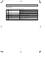
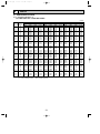
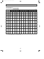
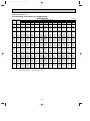
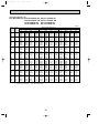
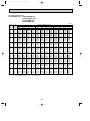
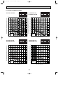
DATA
6-1. PERFORMANCE DATA
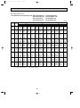
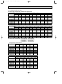
6-1-1. COOLING CAPACITY (1)
PLA-RP1.6AA.UK / PUHZ-RP1.6VHA
(230V)
Indoor Indoor
intake air intake air
D.B.(˚C) W.B.(˚C)
16
20
18
20
20
20
16
22
18
22
20
22
16
24
18
24
20
24
22
24
16
26
18
26
20
26
22
26
16
27
18
27
20
27
22
27
16
28
18
28
20
28
22
28
16
30
18
30
20
30
22
30
16
32
18
32
20
32
22
32
16
34
18
34
20
34
22
34
NOTE:
20
CA
3564
3816
4104
3564
3816
4104
3564
3816
4104
4374
3564
3816
4104
4374
3564
3816
4104
4374
3564
3816
4104
4374
3564
3816
4104
4374
3564
3816
4104
4374
3564
3816
4104
4374
SHC
2816
2557
2257
3101
2862
2586
3386
3167
2914
2581
3564
3473
3242
2931
3564
3625
3406
3106
3564
3778
3570
3281
3564
3816
3899
3630
3564
3816
4104
3980
3564
3816
4104
4330
CA : Capacity (W)
P.C.: Power consumption (kW)
SHF
0.79
0.67
0.55
0.87
0.75
0.63
0.95
0.83
0.71
0.59
1.00
0.91
0.79
0.67
1.00
0.95
0.83
0.71
1.00
0.99
0.87
0.75
1.00
1.00
0.95
0.83
1.00
1.00
1.00
0.91
1.00
1.00
1.00
0.99
P.C.
0.86
0.87
0.90
0.86
0.87
0.90
0.86
0.87
0.90
0.92
0.86
0.87
0.90
0.92
0.86
0.87
0.90
0.92
0.86
0.87
0.90
0.92
0.86
0.87
0.90
0.92
0.86
0.87
0.90
0.92
0.86
0.87
0.90
0.92
Outdoor intale air D.B.(˚C)
25
CA
SHC
SHF
P.C.
0.90
0.79
2730
3456
0.92
0.67
2484
3708
0.94
0.55
2208
4014
0.90
0.87
3007
3456
0.92
0.75
2781
3708
0.94
0.63
2529
4014
0.90
0.95
3283
3456
0.92
0.83
3078
3708
0.94
0.71
2850
4014
0.97
0.59
2528
4284
0.90
1.00
3456
3456
0.92
0.91
3374
3708
0.94
0.79
3171
4014
0.97
0.67
2870
4284
0.90
1.00
3456
3456
0.92
0.95
3523
3708
0.94
0.83
3332
4014
0.97
0.71
3042
4284
0.90
1.00
3456
3456
0.92
0.99
3671
3708
0.94
0.87
3492
4014
0.97
0.75
3213
4284
0.90
1.00
3456
3456
0.92
1.00
3708
3708
0.94
0.95
3813
4014
0.97
0.83
3556
4284
0.90
1.00
3456
3456
0.92
1.00
3708
3708
0.94
1.00
4014
4014
0.97
0.91
3898
4284
0.90
1.00
3456
3456
0.92
1.00
3708
3708
0.94
1.00
4014
4014
0.97
0.99
4241
4284
SHC: Sensible heat capacity (W)
SHF : Sensible heat factor
21
30
CA
3348
3582
3906
3348
3582
3906
3348
3582
3906
4176
3348
3582
3906
4176
3348
3582
3906
4176
3348
3582
3906
4176
3348
3582
3906
4176
3348
3582
3906
4176
3348
3582
3906
4176
SHC
2645
2400
2148
2913
2687
2461
3181
2973
2773
2464
3348
3260
3086
2798
3348
3403
3242
2965
3348
3546
3398
3132
3348
3582
3711
3466
3348
3582
3906
3800
3348
3582
3906
4134
SHF
0.79
0.67
0.55
0.87
0.75
0.63
0.95
0.83
0.71
0.59
1.00
0.91
0.79
0.67
1.00
0.95
0.83
0.71
1.00
0.99
0.87
0.75
1.00
1.00
0.95
0.83
1.00
1.00
1.00
0.91
1.00
1.00
1.00
0.99
P.C.
0.96
0.98
1.01
0.96
0.98
1.01
0.96
0.98
1.01
1.04
0.96
0.98
1.01
1.04
0.96
0.98
1.01
1.04
0.96
0.98
1.01
1.04
0.96
0.98
1.01
1.04
0.96
0.98
1.01
1.04
0.96
0.98
1.01
1.04
OC297-E-1.qxp
05.5.6 5:29 PM
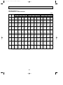
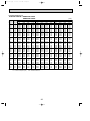
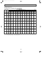
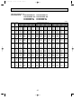
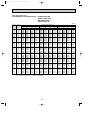
Page 22
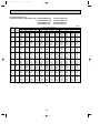
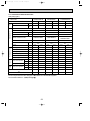
COOLING CAPACITY (2)
PLA-RP1.6AA.UK / PUHZ-RP1.6VHA
(230V)
Indoor Indoor
intake air intake air
D.B.(˚C) W.B.(˚C)
16
20
18
20
20
20
16
22
18
22
20
22
16
24
18
24
20
24
22
24
16
26
18
26
20
26
22
26
16
27
18
27
20
27
22
27
16
28
18
28
20
28
22
28
16
30
18
30
20
30
22
30
16
32
18
32
20
32
22
32
16
34
18
34
20
34
22
34
NOTE:
35
CA
3204
3456
3744
3204
3456
3744
3204
3456
3744
4032
3204
3456
3744
4032
3204
3456
3744
4032
3204
3456
3744
4032
3204
3456
3744
4032
3204
3456
3744
4032
3204
3456
3744
4032
SHC
2531
2316
2059
2787
2592
2359
3044
2868
2658
2379
3204
3145
2958
2701
3204
3283
3108
2863
3204
3421
3257
3024
3204
3456
3557
3347
3204
3456
3744
3669
3204
3456
3744
3992
CA : Capacity (W)
P.C.: Power consumption (kW)
SHF
0.79
0.67
0.55
0.87
0.75
0.63
0.95
0.83
0.71
0.59
1.00
0.91
0.79
0.67
1.00
0.95
0.83
0.71
1.00
0.99
0.87
0.75
1.00
1.00
0.95
0.83
1.00
1.00
1.00
0.91
1.00
1.00
1.00
0.99
P.C.
1.03
1.05
1.08
1.03
1.05
1.08
1.03
1.05
1.08
1.10
1.03
1.05
1.08
1.10
1.03
1.05
1.08
1.10
1.03
1.05
1.08
1.10
1.03
1.05
1.08
1.10
1.03
1.05
1.08
1.10
1.03
1.05
1.08
1.10
Outdoor intale air D.B.(˚C)
40
CA
SHC
SHF
P.C.
1.10
0.79
2417
3060
1.13
0.67
2243
3348
1.16
0.55
1980
3600
1.10
0.87
2662
3060
1.13
0.75
2511
3348
1.16
0.63
2268
3600
1.10
0.95
2907
3060
1.13
0.83
2779
3348
1.16
0.71
2556
3600
1.19
0.59
2294
3888
1.10
1.00
3060
3060
1.13
0.91
3047
3348
1.16
0.79
2844
3600
1.19
0.67
2605
3888
1.10
1.00
3060
3060
1.13
0.95
3181
3348
1.16
0.83
2988
3600
1.19
0.71
2760
3888
1.10
1.00
3060
3060
1.13
0.99
3315
3348
1.16
0.87
3132
3600
1.19
0.75
2916
3888
1.10
1.00
3060
3060
1.13
1.00
3348
3348
1.16
0.95
3420
3600
1.19
0.83
3227
3888
1.10
1.00
3060
3060
1.13
1.00
3348
3348
1.16
1.00
3600
3600
1.19
0.91
3538
3888
1.10
1.00
3060
3060
1.13
1.00
3348
3348
1.16
1.00
3600
3600
1.19
0.99
3849
3888
SHC: Sensible heat capacity (W)
SHF : Sensible heat factor
22
45
CA
2916
3132
3384
2916
3132
3384
2916
3132
3384
3672
2916
3132
3384
3672
2916
3132
3384
3672
2916
3132
3384
3672
2916
3132
3384
3672
2916
3132
3384
3672
2916
3132
3384
3672
SHC
2304
2098
1861
2537
2349
2132
2770
2600
2403
2166
2916
2850
2673
2460
2916
2975
2809
2607
2916
3101
2944
2754
2916
3132
3215
3048
2916
3132
3384
3342
2916
3132
3384
3635
SHF
0.79
0.67
0.55
0.87
0.75
0.63
0.95
0.83
0.71
0.59
1.00
0.91
0.79
0.67
1.00
0.95
0.83
0.71
1.00
0.99
0.87
0.75
1.00
1.00
0.95
0.83
1.00
1.00
1.00
0.91
1.00
1.00
1.00
0.99
P.C.
1.19
1.22
1.24
1.19
1.22
1.24
1.19
1.22
1.24
1.26
1.19
1.22
1.24
1.26
1.19
1.22
1.24
1.26
1.19
1.22
1.24
1.26
1.19
1.22
1.24
1.26
1.19
1.22
1.24
1.26
1.19
1.22
1.24
1.26
OC297-E-1.qxp
05.5.6 5:29 PM
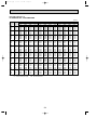
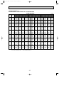
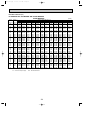
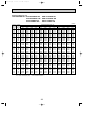
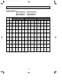
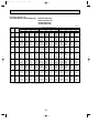
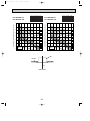
Page 23
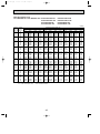
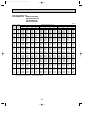
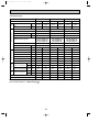
COOLING CAPACITY (3)
PLA-RP2AA.UK / PUHZ-RP2VHA
(230V)
Indoor Indoor
intake air intake air
D.B.(˚C) W.B.(˚C)
16
20
18
20
20
20
16
22
18
22
20
22
16
24
18
24
20
24
22
24
16
26
18
26
20
26
22
26
16
27
18
27
20
27
22
27
16
28
18
28
20
28
22
28
16
30
18
30
20
30
22
30
16
32
18
32
20
32
22
32
16
34
18
34
20
34
22
34
NOTE:
20
CA
4950
5300
5700
4950
5300
5700
4950
5300
5700
6075
4950
5300
5700
6075
4950
5300
5700
6075
4950
5300
5700
6075
4950
5300
5700
6075
4950
5300
5700
6075
4950
5300
5700
6075
SHC
3762
3392
2964
4158
3816
3420
4554
4240
3876
3402
4950
4664
4332
3888
4950
4876
4560
4131
4950
5088
4788
4374
4950
5300
5244
4860
4950
5300
5700
5346
4950
5300
5700
5832
CA : Capacity (W)
P.C.: Power consumption (kW)
SHF
0.76
0.64
0.52
0.84
0.72
0.60
0.92
0.80
0.68
0.56
1.00
0.88
0.76
0.64
1.00
0.92
0.80
0.68
1.00
0.96
0.84
0.72
1.00
1.00
0.92
0.80
1.00
1.00
1.00
0.88
1.00
1.00
1.00
0.96
P.C.
1.24
1.26
1.30
1.24
1.26
1.30
1.24
1.26
1.30
1.33
1.24
1.26
1.30
1.33
1.24
1.26
1.30
1.33
1.24
1.26
1.30
1.33
1.24
1.26
1.30
1.33
1.24
1.26
1.30
1.33
1.24
1.26
1.30
1.33
Outdoor intale air D.B.(˚C)
25
CA
SHC
SHF
P.C.
1.31
0.76
3648
4800
1.33
0.64
3296
5150
1.36
0.52
2899
5575
1.31
0.84
4032
4800
1.33
0.72
3708
5150
1.36
0.60
3345
5575
1.31
0.92
4416
4800
1.33
0.80
4120
5150
1.36
0.68
3791
5575
1.41
0.56
3332
5950
1.31
1.00
4800
4800
1.33
0.88
4532
5150
1.36
0.76
4237
5575
1.41
0.64
3808
5950
1.31
1.00
4800
4800
1.33
0.92
4738
5150
1.36
0.80
4460
5575
1.41
0.68
4046
5950
1.31
1.00
4800
4800
1.33
0.96
4944
5150
1.36
0.84
4683
5575
1.41
0.72
4284
5950
1.31
1.00
4800
4800
1.33
1.00
5150
5150
1.36
0.92
5129
5575
1.41
0.80
4760
5950
1.31
1.00
4800
4800
1.33
1.00
5150
5150
1.36
1.00
5575
5575
1.41
0.88
5236
5950
1.31
1.00
4800
4800
1.33
1.00
5150
5150
1.36
1.00
5575
5575
1.41
0.96
5712
5950
SHC: Sensible heat capacity (W)
SHF : Sensible heat factor
23
30
CA
4650
4975
5425
4650
4975
5425
4650
4975
5425
5800
4650
4975
5425
5800
4650
4975
5425
5800
4650
4975
5425
5800
4650
4975
5425
5800
4650
4975
5425
5800
4650
4975
5425
5800
SHC
3534
3184
2821
3906
3582
3255
4278
3980
3689
3248
4650
4378
4123
3712
4650
4577
4340
3944
4650
4776
4557
4176
4650
4975
4991
4640
4650
4975
5425
5104
4650
4975
5425
5568
SHF
0.76
0.64
0.52
0.84
0.72
0.60
0.92
0.80
0.68
0.56
1.00
0.88
0.76
0.64
1.00
0.92
0.80
0.68
1.00
0.96
0.84
0.72
1.00
1.00
0.92
0.80
1.00
1.00
1.00
0.88
1.00
1.00
1.00
0.96
P.C.
1.39
1.43
1.46
1.39
1.43
1.46
1.39
1.43
1.46
1.50
1.39
1.43
1.46
1.50
1.39
1.43
1.46
1.50
1.39
1.43
1.46
1.50
1.39
1.43
1.46
1.50
1.39
1.43
1.46
1.50
1.39
1.43
1.46
1.50
OC297-E-1.qxp
05.5.6 5:29 PM
Page 24
COOLING CAPACITY (4)
PLA-RP2AA.UK / PUHZ-RP2VHA
(230V)
Indoor Indoor
intake air intake air
D.B.(˚C) W.B.(˚C)
16
20
18
20
20
20
16
22
18
22
20
22
16
24
18
24
20
24
22
24
16
26
18
26
20
26
22
26
16
27
18
27
20
27
22
27
16
28
18
28
20
28
22
28
16
30
18
30
20
30
22
30
16
32
18
32
20
32
22
32
16
34
18
34
20
34
22
34
NOTE:
35
CA
4450
4800
5200
4450
4800
5200
4450
4800
5200
5600
4450
4800
5200
5600
4450
4800
5200
5600
4450
4800
5200
5600
4450
4800
5200
5600
4450
4800
5200
5600
4450
4800
5200
5600
SHC
3382
3072
2704
3738
3456
3120
4094
3840
3536
3136
4450
4224
3952
3584
4450
4416
4160
3808
4450
4608
4368
4032
4450
4800
4784
4480
4450
4800
5200
4928
4450
4800
5200
5376
CA : Capacity (W)
P.C.: Power consumption (kW)
SHF
0.76
0.64
0.52
0.84
0.72
0.60
0.92
0.80
0.68
0.56
1.00
0.88
0.76
0.64
1.00
0.92
0.80
0.68
1.00
0.96
0.84
0.72
1.00
1.00
0.92
0.80
1.00
1.00
1.00
0.88
1.00
1.00
1.00
0.96
P.C.
1.49
1.53
1.57
1.49
1.53
1.57
1.49
1.53
1.57
1.60
1.49
1.53
1.57
1.60
1.49
1.53
1.57
1.60
1.49
1.53
1.57
1.60
1.49
1.53
1.57
1.60
1.49
1.53
1.57
1.60
1.49
1.53
1.57
1.60
Outdoor intale air D.B.(˚C)
40
CA
SHC
SHF
P.C.
1.60
0.76
3230
4250
1.64
0.64
2976
4650
1.67
0.52
2600
5000
1.60
0.84
3570
4250
1.64
0.72
3348
4650
1.67
0.60
3000
5000
1.60
0.92
3910
4250
1.64
0.80
3720
4650
1.67
0.68
3400
5000
1.72
0.56
3024
5400
1.60
1.00
4250
4250
1.64
0.88
4092
4650
1.67
0.76
3800
5000
1.72
0.64
3456
5400
1.60
1.00
4250
4250
1.64
0.92
4278
4650
1.67
0.80
4000
5000
1.72
0.68
3672
5400
1.60
1.00
4250
4250
1.64
0.96
4464
4650
1.67
0.84
4200
5000
1.72
0.72
3888
5400
1.60
1.00
4250
4250
1.64
1.00
4650
4650
1.67
0.92
4600
5000
1.72
0.80
4320
5400
1.60
1.00
4250
4250
1.64
1.00
4650
4650
1.67
1.00
5000
5000
1.72
0.88
4752
5400
1.60
1.00
4250
4250
1.64
1.00
4650
4650
1.67
1.00
5000
5000
1.72
0.96
5184
5400
SHC: Sensible heat capacity (W)
SHF : Sensible heat factor
24
45
CA
4050
4350
4700
4050
4350
4700
4050
4350
4700
5100
4050
4350
4700
5100
4050
4350
4700
5100
4050
4350
4700
5100
4050
4350
4700
5100
4050
4350
4700
5100
4050
4350
4700
5100
SHC
3078
2784
2444
3402
3132
2820
3726
3480
3196
2856
4050
3828
3572
3264
4050
4002
3760
3468
4050
4176
3948
3672
4050
4350
4324
4080
4050
4350
4700
4488
4050
4350
4700
4896
SHF
0.76
0.64
0.52
0.84
0.72
0.60
0.92
0.80
0.68
0.56
1.00
0.88
0.76
0.64
1.00
0.92
0.80
0.68
1.00
0.96
0.84
0.72
1.00
1.00
0.92
0.80
1.00
1.00
1.00
0.88
1.00
1.00
1.00
0.96
P.C.
1.73
1.77
1.80
1.73
1.77
1.80
1.73
1.77
1.80
1.83
1.73
1.77
1.80
1.83
1.73
1.77
1.80
1.83
1.73
1.77
1.80
1.83
1.73
1.77
1.80
1.83
1.73
1.77
1.80
1.83
1.73
1.77
1.80
1.83
OC297-E-1.qxp
05.5.6 5:29 PM
Page 25
COOLING CAPACITY (5)
PLA-RP2.5AA.UK / PUHZ-RP2.5VHA
PUHZ-RP2.5VHA1
Indoor Indoor
intake air intake air
D.B.(˚C) W.B.(˚C)
16
20
18
20
20
20
16
22
18
22
20
22
16
24
18
24
20
24
22
24
16
26
18
26
20
26
22
26
16
27
18
27
20
27
22
27
16
28
18
28
20
28
22
28
16
30
18
30
20
30
22
30
16
32
18
32
20
32
22
32
16
34
18
34
20
34
22
34
NOTE:
20
CA
5940
6360
6840
5940
6360
6840
5940
6360
6840
7290
5940
6360
6840
7290
5940
6360
6840
7290
5940
6360
6840
7290
5940
6360
6840
7290
5940
6360
6840
7290
5940
6360
6840
7290
SHC
4039
3562
3010
4514
4070
3557
4990
4579
4104
3499
5465
5088
4651
4082
5702
5342
4925
4374
5940
5597
5198
4666
5940
6106
5746
5249
5940
6360
6293
5832
5940
6360
6840
6415
CA : Capacity (W)
P.C.: Power consumption (kW)
SHF
0.68
0.56
0.44
0.76
0.64
0.52
0.84
0.72
0.60
0.48
0.92
0.80
0.68
0.56
0.96
0.84
0.72
0.60
1.00
0.88
0.76
0.64
1.00
0.96
0.84
0.72
1.00
1.00
0.92
0.80
1.00
1.00
1.00
0.88
P.C.
1.32
1.34
1.39
1.32
1.34
1.39
1.32
1.34
1.39
1.42
1.32
1.34
1.39
1.42
1.32
1.34
1.39
1.42
1.32
1.34
1.39
1.42
1.32
1.34
1.39
1.42
1.32
1.34
1.39
1.42
1.32
1.34
1.39
1.42
(230V)
Outdoor intale air D.B.(˚C)
25
CA
SHC
SHF
P.C.
1.39
0.68
3917
5760
1.42
0.56
3461
6180
1.45
0.44
2944
6690
1.39
0.76
4378
5760
1.42
0.64
3955
6180
1.45
0.52
3479
6690
1.39
0.84
4838
5760
1.42
0.72
4450
6180
1.45
0.60
4014
6690
1.50
0.48
3427
7140
1.39
0.92
5299
5760
1.42
0.80
4944
6180
1.45
0.68
4549
6690
1.50
0.56
3998
7140
1.39
0.96
5530
5760
1.42
0.84
5191
6180
1.45
0.72
4817
6690
1.50
0.60
4284
7140
1.39
1.00
5760
5760
1.42
0.88
5438
6180
1.45
0.76
5084
6690
1.50
0.64
4570
7140
1.39
1.00
5760
5760
1.42
0.96
5933
6180
1.45
0.84
5620
6690
1.50
0.72
5141
7140
1.39
1.00
5760
5760
1.42
1.00
6180
6180
1.45
0.92
6155
6690
1.50
0.80
5712
7140
1.39
1.00
5760
5760
1.42
1.00
6180
6180
1.45
1.00
6690
6690
1.50
0.88
6283
7140
SHC: Sensible heat capacity (W)
SHF : Sensible heat factor
25
30
CA
5580
5970
6510
5580
5970
6510
5580
5970
6510
6960
5580
5970
6510
6960
5580
5970
6510
6960
5580
5970
6510
6960
5580
5970
6510
6960
5580
5970
6510
6960
5580
5970
6510
6960
SHC
3794
3343
2864
4241
3821
3385
4687
4298
3906
3341
5134
4776
4427
3898
5357
5015
4687
4176
5580
5254
4948
4454
5580
5731
5468
5011
5580
5970
5989
5568
5580
5970
6510
6125
SHF
0.68
0.56
0.44
0.76
0.64
0.52
0.84
0.72
0.60
0.48
0.92
0.80
0.68
0.56
0.96
0.84
0.72
0.60
1.00
0.88
0.76
0.64
1.00
0.96
0.84
0.72
1.00
1.00
0.92
0.80
1.00
1.00
1.00
0.88
P.C.
1.48
1.52
1.55
1.48
1.52
1.55
1.48
1.52
1.55
1.60
1.48
1.52
1.55
1.60
1.48
1.52
1.55
1.60
1.48
1.52
1.55
1.60
1.48
1.52
1.55
1.60
1.48
1.52
1.55
1.60
1.48
1.52
1.55
1.60
OC297-E-1.qxp
05.5.6 5:29 PM
Page 26
COOLING CAPACITY (6)
PLA-RP2.5AA.UK / PUHZ-RP2.5VHA
PUHZ-RP2.5VHA1
Indoor Indoor
intake air intake air
D.B.(˚C) W.B.(˚C)
16
20
18
20
20
20
16
22
18
22
20
22
16
24
18
24
20
24
22
24
16
26
18
26
20
26
22
26
16
27
18
27
20
27
22
27
16
28
18
28
20
28
22
28
16
30
18
30
20
30
22
30
16
32
18
32
20
32
22
32
16
34
18
34
20
34
22
34
NOTE:
35
CA
5340
5760
6240
5340
5760
6240
5340
5760
6240
6720
5340
5760
6240
6720
5340
5760
6240
6720
5340
5760
6240
6720
5340
5760
6240
6720
5340
5760
6240
6720
5340
5760
6240
6720
SHC
3631
3226
2746
4058
3686
3245
4486
4147
3744
3226
4913
4608
4243
3763
5126
4838
4493
4032
5340
5069
4742
4301
5340
5530
5242
4838
5340
5760
5741
5376
5340
5760
6240
5914
CA : Capacity (W)
P.C.: Power consumption (kW)
SHF
0.68
0.56
0.44
0.76
0.64
0.52
0.84
0.72
0.60
0.48
0.92
0.80
0.68
0.56
0.96
0.84
0.72
0.60
1.00
0.88
0.76
0.64
1.00
0.96
0.84
0.72
1.00
1.00
0.92
0.80
1.00
1.00
1.00
0.88
P.C.
1.58
1.63
1.67
1.58
1.63
1.67
1.58
1.63
1.67
1.70
1.58
1.63
1.67
1.70
1.58
1.63
1.67
1.70
1.58
1.63
1.67
1.70
1.58
1.63
1.67
1.70
1.58
1.63
1.67
1.70
1.58
1.63
1.67
1.70
(230V)
Outdoor intale air D.B.(˚C)
40
CA
SHC
SHF
P.C.
1.70
0.68
3468
5100
1.75
0.56
3125
5580
1.78
0.44
2640
6000
1.70
0.76
3876
5100
1.75
0.64
3571
5580
1.78
0.52
3120
6000
1.70
0.84
4284
5100
1.75
0.72
4018
5580
1.78
0.60
3600
6000
1.83
0.48
3110
6480
1.70
0.92
4692
5100
1.75
0.80
4464
5580
1.78
0.68
4080
6000
1.83
0.56
3629
6480
1.70
0.96
4896
5100
1.75
0.84
4687
5580
1.78
0.72
4320
6000
1.83
0.60
3888
6480
1.70
1.00
5100
5100
1.75
0.88
4910
5580
1.78
0.76
4560
6000
1.83
0.64
4147
6480
1.70
1.00
5100
5100
1.75
0.96
5357
5580
1.78
0.84
5040
6000
1.83
0.72
4666
6480
1.70
1.00
5100
5100
1.75
1.00
5580
5580
1.78
0.92
5520
6000
1.83
0.80
5184
6480
1.70
1.00
5100
5100
1.75
1.00
5580
5580
1.78
1.00
6000
6000
1.83
0.88
5702
6480
SHC: Sensible heat capacity (W)
SHF : Sensible heat factor
26
45
CA
4860
5220
5640
4860
5220
5640
4860
5220
5640
6120
4860
5220
5640
6120
4860
5220
5640
6120
4860
5220
5640
6120
4860
5220
5640
6120
4860
5220
5640
6120
4860
5220
5640
6120
SHC
3305
2923
2482
3694
3341
2933
4082
3758
3384
2938
4471
4176
3835
3427
4666
4385
4061
3672
4860
4594
4286
3917
4860
5011
4738
4406
4860
5220
5189
4896
4860
5220
5640
5386
SHF
0.68
0.56
0.44
0.76
0.64
0.52
0.84
0.72
0.60
0.48
0.92
0.80
0.68
0.56
0.96
0.84
0.72
0.60
1.00
0.88
0.76
0.64
1.00
0.96
0.84
0.72
1.00
1.00
0.92
0.80
1.00
1.00
1.00
0.88
P.C.
1.84
1.88
1.91
1.84
1.88
1.91
1.84
1.88
1.91
1.95
1.84
1.88
1.91
1.95
1.84
1.88
1.91
1.95
1.84
1.88
1.91
1.95
1.84
1.88
1.91
1.95
1.84
1.88
1.91
1.95
1.84
1.88
1.91
1.95
OC297-E-1.qxp
05.5.6 5:29 PM
Page 27
COOLING CAPACITY (7)
PLA-RP3AA.UK PLA-RP3AA1.UK / PUHZ-RP3VHA
PUHZ-RP3VHA1
Indoor Indoor
intake air intake air
D.B.(˚C) W.B.(˚C)
16
20
18
20
20
20
16
22
18
22
20
22
16
24
18
24
20
24
22
24
16
26
18
26
20
26
22
26
16
27
18
27
20
27
22
27
16
28
18
28
20
28
22
28
16
30
18
30
20
30
22
30
16
32
18
32
20
32
22
32
16
34
18
34
20
34
22
34
NOTE:
20
CA
7,029
7,526
8,094
7,029
7,526
8,094
7,029
7,526
8,094
8,627
7,029
7,526
8,094
8,627
7,029
7,526
8,094
8,627
7,029
7,526
8,094
8,627
7,029
7,526
8,094
8,627
7,029
7,526
8,094
8,627
7,029
7,526
8,094
8,627
SHC
4,499
3,914
3,238
5,061
4,516
3,885
5,623
5,118
4,533
3,796
6,186
5,720
5,180
4,486
6,467
6,021
5,504
4,831
6,748
6,322
5,828
5,176
7,029
6,924
6,475
5,866
7,029
7,526
7,123
6,556
7,029
7,526
7,770
7,246
CA : Capacity (W)
P.C.: Power consumption (kW)
SHF
0.64
0.52
0.40
0.72
0.60
0.48
0.80
0.68
0.56
0.44
0.88
0.76
0.64
0.52
0.92
0.80
0.68
0.56
0.96
0.84
0.72
0.60
1.00
0.92
0.80
0.68
1.00
1.00
0.88
0.76
1.00
1.00
0.96
0.84
P.C.
1.58
1.61
1.65
1.58
1.61
1.65
1.58
1.61
1.65
1.69
1.58
1.61
1.65
1.69
1.58
1.61
1.65
1.69
1.58
1.61
1.65
1.69
1.58
1.61
1.65
1.69
1.58
1.61
1.65
1.69
1.58
1.61
1.65
1.69
Outdoor intale air D.B.(˚C)
25
CA
SHC
SHF
P.C.
1.66
0.64
4,362
6,816
1.69
0.52
3,803
7,313
1.73
0.40
3,167
7,917
1.66
0.72
4,908
6,816
1.69
0.60
4,388
7,313
1.73
0.48
3,800
7,917
1.66
0.80
5,453
6,816
1.69
0.68
4,973
7,313
1.73
0.56
4,433
7,917
1.79
0.44
3,718
8,449
1.66
0.88
5,998
6,816
1.69
0.76
5,558
7,313
1.73
0.64
5,067
7,917
1.79
0.52
4,393
8,449
1.66
0.92
6,271
6,816
1.69
0.80
5,850
7,313
1.73
0.68
5,383
7,917
1.79
0.56
4,731
8,449
1.66
0.96
6,543
6,816
1.69
0.84
6,143
7,313
1.73
0.72
5,700
7,917
1.79
0.60
5,069
8,449
1.66
1.00
6,816
6,816
1.69
0.92
6,728
7,313
1.73
0.80
6,333
7,917
1.79
0.68
5,745
8,449
1.66
1.00
6,816
6,816
1.69
1.00
7,313
7,313
1.73
0.88
6,967
7,917
1.79
0.76
6,421
8,449
1.66
1.00
6,816
6,816
1.69
1.00
7,313
7,313
1.73
0.96
7,600
7,917
1.79
0.84
7,097
8,449
SHC: Sensible heat capacity (W)
SHF : Sensible heat factor
27
(230V)
30
CA
6,603
7,065
7,704
6,603
7,065
7,704
6,603
7,065
7,704
8,236
6,603
7,065
7,704
8,236
6,603
7,065
7,704
8,236
6,603
7,065
7,704
8,236
6,603
7,065
7,704
8,236
6,603
7,065
7,704
8,236
6,603
7,065
7,704
8,236
SHC
4,226
3,674
3,081
4,754
4,239
3,698
5,282
4,804
4,314
3,624
5,811
5,369
4,930
4,283
6,075
5,652
5,238
4,612
6,339
5,934
5,547
4,942
6,603
6,499
6,163
5,600
6,603
7,065
6,779
6,259
6,603
7,065
7,395
6,918
SHF
0.64
0.52
0.40
0.72
0.60
0.48
0.80
0.68
0.56
0.44
0.88
0.76
0.64
0.52
0.92
0.80
0.68
0.56
0.96
0.84
0.72
0.60
1.00
0.92
0.80
0.68
1.00
1.00
0.88
0.76
1.00
1.00
0.96
0.84
P.C.
1.76
1.81
1.85
1.76
1.81
1.85
1.76
1.81
1.85
1.91
1.76
1.81
1.85
1.91
1.76
1.81
1.85
1.91
1.76
1.81
1.85
1.91
1.76
1.81
1.85
1.91
1.76
1.81
1.85
1.91
1.76
1.81
1.85
1.91
OC297-E-1.qxp
05.5.6 5:29 PM
Page 28
COOLING CAPACITY (8)
PLA-RP3AA.UK PLA-RP3AA1.UK / PUHZ-RP3VHA
PUHZ-RP3VHA1
Indoor Indoor
intake air intake air
D.B.(˚C) W.B.(˚C)
16
20
18
20
20
20
16
22
18
22
20
22
16
24
18
24
20
24
22
24
16
26
18
26
20
26
22
26
16
27
18
27
20
27
22
27
16
28
18
28
20
28
22
28
16
30
18
30
20
30
22
30
16
32
18
32
20
32
22
32
16
34
18
34
20
34
22
34
NOTE:
35
CA
6,319
6,816
7,384
6,319
6,816
7,384
6,319
6,816
7,384
7,952
6,319
6,816
7,384
7,952
6,319
6,816
7,384
7,952
6,319
6,816
7,384
7,952
6,319
6,816
7,384
7,952
6,319
6,816
7,384
7,952
6,319
6,816
7,384
7,952
SHC
4,044
3,544
2,954
4,550
4,090
3,544
5,055
4,635
4,135
3,499
5,561
5,180
4,726
4,135
5,813
5,453
5,021
4,453
6,066
5,725
5,316
4,771
6,319
6,271
5,907
5,407
6,319
6,816
6,498
6,044
6,319
6,816
7,089
6,680
CA : Capacity (W)
P.C.: Power consumption (kW)
SHF
0.64
0.52
0.40
0.72
0.60
0.48
0.80
0.68
0.56
0.44
0.88
0.76
0.64
0.52
0.92
0.80
0.68
0.56
0.96
0.84
0.72
0.60
1.00
0.92
0.80
0.68
1.00
1.00
0.88
0.76
1.00
1.00
0.96
0.84
P.C.
1.89
1.94
1.99
1.89
1.94
1.99
1.89
1.94
1.99
2.03
1.89
1.94
1.99
2.03
1.89
1.94
1.99
2.03
1.89
1.94
1.99
2.03
1.89
1.94
1.99
2.03
1.89
1.94
1.99
2.03
1.89
1.94
1.99
2.03
Outdoor intale air D.B.(˚C)
40
CA
SHC
SHF
P.C.
2.03
0.64
3,862
6,035
2.09
0.52
3,434
6,603
2.13
0.40
2,840
7,100
2.03
0.72
4,345
6,035
2.09
0.60
3,962
6,603
2.13
0.48
3,408
7,100
2.03
0.80
4,828
6,035
2.09
0.68
4,490
6,603
2.13
0.56
3,976
7,100
2.19
0.44
3,374
7,668
2.03
0.88
5,311
6,035
2.09
0.76
5,018
6,603
2.13
0.64
4,544
7,100
2.19
0.52
3,987
7,668
2.03
0.92
5,552
6,035
2.09
0.80
5,282
6,603
2.13
0.68
4,828
7,100
2.19
0.56
4,294
7,668
2.03
0.96
5,794
6,035
2.09
0.84
5,547
6,603
2.13
0.72
5,112
7,100
2.19
0.60
4,601
7,668
2.03
1.00
6,035
6,035
2.09
0.92
6,075
6,603
2.13
0.80
5,680
7,100
2.19
0.68
5,214
7,668
2.03
1.00
6,035
6,035
2.09
1.00
6,603
6,603
2.13
0.88
6,248
7,100
2.19
0.76
5,828
7,668
2.03
1.00
6,035
6,035
2.09
1.00
6,603
6,603
2.13
0.96
6,816
7,100
2.19
0.84
6,441
7,668
SHC: Sensible heat capacity (W)
SHF : Sensible heat factor
28
(230V)
45
CA
5,751
6,177
6,674
5,751
6,177
6,674
5,751
6,177
6,674
7,242
5,751
6,177
6,674
7,242
5,751
6,177
6,674
7,242
5,751
6,177
6,674
7,242
5,751
6,177
6,674
7,242
5,751
6,177
6,674
7,242
5,751
6,177
6,674
7,242
SHC
3,681
3,212
2,670
4,141
3,706
3,204
4,601
4,200
3,737
3,186
5,061
4,695
4,271
3,766
5,291
4,942
4,538
4,056
5,521
5,189
4,805
4,345
5,751
5,683
5,339
4,925
5,751
6,177
5,873
5,504
5,751
6,177
6,407
6,083
SHF
0.64
0.52
0.40
0.72
0.60
0.48
0.80
0.68
0.56
0.44
0.88
0.76
0.64
0.52
0.92
0.80
0.68
0.56
0.96
0.84
0.72
0.60
1.00
0.92
0.80
0.68
1.00
1.00
0.88
0.76
1.00
1.00
0.96
0.84
P.C.
2.20
2.25
2.29
2.20
2.25
2.29
2.20
2.25
2.29
2.32
2.20
2.25
2.29
2.32
2.20
2.25
2.29
2.32
2.20
2.25
2.29
2.32
2.20
2.25
2.29
2.32
2.20
2.25
2.29
2.32
2.20
2.25
2.29
2.32
OC297-E-1.qxp
05.5.6 5:29 PM
Page 29
COOLING CAPACITY (9)
PLA-RP4AA.UK PLA-RP4AA1.UK / PUHZ-RP4VHA
PUHZ-RP4VHA1
Indoor Indoor
intake air intake air
D.B.(˚C) W.B.(˚C) CA
9,900
16
20
10,600
18
20
11,400
20
20
9,900
16
22
10,600
18
22
11,400
20
22
9,900
16
24
10,600
18
24
11,400
20
24
12,150
22
24
9,900
16
26
10,600
18
26
11,400
20
26
12,150
22
26
9,900
16
27
10,600
18
27
11,400
20
27
12,150
22
27
9,900
16
28
10,600
18
28
11,400
20
28
12,150
22
28
9,900
16
30
10,600
18
30
11,400
20
30
12,150
22
30
9,900
16
32
10,600
18
32
11,400
20
32
12,150
22
32
9,900
16
34
10,600
18
34
11,400
20
34
12,150
22
34
NOTE:
20
SHC
6,435
5,618
4,674
7,227
6,466
5,586
8,019
7,314
6,498
5,468
8,811
8,162
7,410
6,440
9,207
8,586
7,866
6,926
9,603
9,010
8,322
7,412
9,900
9,858
9,234
8,384
9,900
10,600
10,146
9,356
9,900
10,600
11,058
10,328
CA : Capacity (W)
P.C.: Power consumption (kW)
SHF
0.65
0.53
0.41
0.73
0.61
0.49
0.81
0.69
0.57
0.45
0.89
0.77
0.65
0.53
0.93
0.81
0.69
0.57
0.97
0.85
0.73
0.61
1.00
0.93
0.81
0.69
1.00
1.00
0.89
0.77
1.00
1.00
0.97
0.85
P.C.
2.42
2.47
2.55
2.42
2.47
2.55
2.42
2.47
2.55
2.61
2.42
2.47
2.55
2.61
2.42
2.47
2.55
2.61
2.42
2.47
2.55
2.61
2.42
2.47
2.55
2.61
2.42
2.47
2.55
2.61
2.42
2.47
2.55
2.61
Outdoor intale air D.B.(˚C)
25
CA
SHC
SHF
P.C.
2.56
0.65
6,240
9,600
2.61
0.53
10,300 5,459
2.67
0.41
11,150 4,572
2.56
0.73
7,008
9,600
2.61
0.61
10,300 6,283
2.67
0.49
11,150 5,464
2.56
0.81
7,776
9,600
2.61
0.69
10,300 7,107
2.67
0.57
11,150 6,356
2.76
0.45
11,900 5,355
2.56
0.89
8,544
9,600
2.61
0.77
10,300 7,931
2.67
0.65
11,150 7,248
2.76
0.53
11,900 6,307
2.56
0.93
8,928
9,600
2.61
0.81
10,300 8,343
2.67
0.69
11,150 7,694
2.76
0.57
11,900 6,783
2.56
0.97
9,312
9,600
2.61
0.85
10,300 8,755
2.67
0.73
11,150 8,140
2.76
0.61
11,900 7,259
2.56
1.00
9,600
9,600
2.61
0.93
10,300 9,579
2.67
0.81
11,150 9,032
2.76
0.69
11,900 8,211
2.56
1.00
9,600
9,600
2.61
1.00
10,300 10,300
2.67
0.89
11,150 9,924
2.76
0.77
11,900 9,163
2.56
1.00
9,600
9,600
2.61
1.00
10,300 10,300
2.67
0.97
11,150 10,816
2.76
0.85
11,900 10,115
SHC: Sensible heat capacity (W)
SHF : Sensible heat factor
29
(230V)
CA
9,300
9,950
10,850
9,300
9,950
10,850
9,300
9,950
10,850
11,600
9,300
9,950
10,850
11,600
9,300
9,950
10,850
11,600
9,300
9,950
10,850
11,600
9,300
9,950
10,850
11,600
9,300
9,950
10,850
11,600
9,300
9,950
10,850
11,600
30
SHC
6,045
5,274
4,449
6,789
6,070
5,317
7,533
6,866
6,185
5,220
8,277
7,662
7,053
6,148
8,649
8,060
7,487
6,612
9,021
8,458
7,921
7,076
9,300
9,254
8,789
8,004
9,300
9,950
9,657
8,932
9,300
9,950
10,525
9,860
SHF
0.65
0.53
0.41
0.73
0.61
0.49
0.81
0.69
0.57
0.45
0.89
0.77
0.65
0.53
0.93
0.81
0.69
0.57
0.97
0.85
0.73
0.61
1.00
0.93
0.81
0.69
1.00
1.00
0.89
0.77
1.00
1.00
0.97
0.85
P.C.
2.71
2.79
2.85
2.71
2.79
2.85
2.71
2.79
2.85
2.94
2.71
2.79
2.85
2.94
2.71
2.79
2.85
2.94
2.71
2.79
2.85
2.94
2.71
2.79
2.85
2.94
2.71
2.79
2.85
2.94
2.71
2.79
2.85
2.94
OC297-E-1.qxp
05.5.6 5:29 PM
Page 30
COOLING CAPACITY (10)
PLA-RP4AA.UK PLA-RP4AA1.UK / PUHZ-RP4VHA
PUHZ-RP4VHA1
Indoor Indoor
intake air intake air
D.B.(˚C) W.B.(˚C) CA
8,900
16
20
9,600
18
20
10,400
20
20
8,900
16
22
9,600
18
22
10,400
20
22
8,900
16
24
9,600
18
24
10,400
20
24
11,200
22
24
8,900
16
26
9,600
18
26
10,400
20
26
11,200
22
26
8,900
16
27
9,600
18
27
10,400
20
27
11,200
22
27
8,900
16
28
9,600
18
28
10,400
20
28
11,200
22
28
8,900
16
30
9,600
18
30
10,400
20
30
11,200
22
30
8,900
16
32
9,600
18
32
10,400
20
32
11,200
22
32
8,900
16
34
9,600
18
34
10,400
20
34
11,200
22
34
NOTE:
35
SHC
5,785
5,088
4,264
6,497
5,856
5,096
7,209
6,624
5,928
5,040
7,921
7,392
6,760
5,936
8,277
7,776
7,176
6,384
8,633
8,160
7,592
6,832
8,900
8,928
8,424
7,728
8,900
9,600
9,256
8,624
8,900
9,600
10,088
9,520
CA : Capacity (W)
P.C.: Power consumption (kW)
SHF
0.65
0.53
0.41
0.73
0.61
0.49
0.81
0.69
0.57
0.45
0.89
0.77
0.65
0.53
0.93
0.81
0.69
0.57
0.97
0.85
0.73
0.61
1.00
0.93
0.81
0.69
1.00
1.00
0.89
0.77
1.00
1.00
0.97
0.85
P.C.
2.91
2.98
3.06
2.91
2.98
3.06
2.91
2.98
3.06
3.12
2.91
2.98
3.06
3.12
2.91
2.98
3.06
3.12
2.91
2.98
3.06
3.12
2.91
2.98
3.06
3.12
2.91
2.98
3.06
3.12
2.91
2.98
3.06
3.12
Outdoor intale air D.B.(˚C)
40
CA
SHC
SHF
P.C.
3.12
0.65
5,525
8,500
3.21
0.53
4,929
9,300
3.27
0.41
10,000 4,100
3.12
0.73
6,205
8,500
3.21
0.61
5,673
9,300
3.27
0.49
10,000 4,900
3.12
0.81
6,885
8,500
3.21
0.69
6,417
9,300
3.27
0.57
10,000 5,700
3.36
0.45
10,800 4,860
3.12
0.89
7,565
8,500
3.21
0.77
7,161
9,300
3.27
0.65
10,000 6,500
3.36
0.53
10,800 5,724
3.12
0.93
7,905
8,500
3.21
0.81
7,533
9,300
3.27
0.69
10,000 6,900
3.36
0.57
10,800 6,156
3.12
0.97
8,245
8,500
3.21
0.85
7,905
9,300
3.27
0.73
10,000 7,300
3.36
0.61
10,800 6,588
3.12
1.00
8,500
8,500
3.21
0.93
8,649
9,300
3.27
0.81
10,000 8,100
3.36
0.69
10,800 7,452
3.12
1.00
8,500
8,500
3.21
1.00
9,300
9,300
3.27
0.89
10,000 8,900
3.36
0.77
10,800 8,316
3.12
1.00
8,500
8,500
3.21
1.00
9,300
9,300
3.27
0.97
10,000 9,700
3.36
0.85
10,800 9,180
SHC: Sensible heat capacity (W)
SHF : Sensible heat factor
30
(230V)
45
CA
8,100
8,700
9,400
8,100
8,700
9,400
8,100
8,700
9,400
10,200
8,100
8,700
9,400
10,200
8,100
8,700
9,400
10,200
8,100
8,700
9,400
10,200
8,100
8,700
9,400
10,200
8,100
8,700
9,400
10,200
8,100
8,700
9,400
10,200
SHC
5,265
4,611
3,854
5,913
5,307
4,606
6,561
6,003
5,358
4,590
7,209
6,699
6,110
5,406
7,533
7,047
6,486
5,814
7,857
7,395
6,862
6,222
8,100
8,091
7,614
7,038
8,100
8,700
8,366
7,854
8,100
8,700
9,118
8,670
SHF
0.65
0.53
0.41
0.73
0.61
0.49
0.81
0.69
0.57
0.45
0.89
0.77
0.65
0.53
0.93
0.81
0.69
0.57
0.97
0.85
0.73
0.61
1.00
0.93
0.81
0.69
1.00
1.00
0.89
0.77
1.00
1.00
0.97
0.85
P.C.
3.38
3.45
3.51
3.38
3.45
3.51
3.38
3.45
3.51
3.58
3.38
3.45
3.51
3.58
3.38
3.45
3.51
3.58
3.38
3.45
3.51
3.58
3.38
3.45
3.51
3.58
3.38
3.45
3.51
3.58
3.38
3.45
3.51
3.58
OC297-E-2.qxp
05.5.6 5:34 PM
Page 31
COOLING CAPACITY (11)
PLA-RP5AA.UK PLA-RP5AA1.UK / PUHZ-RP5VHA
PUHZ-RP5VHA1
Indoor Indoor
intake air intake air
D.B.(˚C) W.B.(˚C) CA
12,375
16
20
13,250
18
20
14,250
20
20
12,375
16
22
13,250
18
22
14,250
20
22
12,375
16
24
13,250
18
24
14,250
20
24
15,188
22
24
12,375
16
26
13,250
18
26
14,250
20
26
15,188
22
26
12,375
16
27
13,250
18
27
14,250
20
27
15,188
22
27
12,375
16
28
13,250
18
28
14,250
20
28
15,188
22
28
12,375
16
30
13,250
18
30
14,250
20
30
15,188
22
30
12,375
16
32
13,250
18
32
14,250
20
32
15,188
22
32
12,375
16
34
13,250
18
34
14,250
20
34
15,188
22
34
NOTE:
20
SHC
7,920
6,890
5,700
8,910
7,950
6,840
9,900
9,010
7,980
6,683
10,890
10,070
9,120
7,898
11,385
10,600
9,690
8,505
11,880
11,130
10,260
9,113
12,375
12,190
11,400
10,328
12,375
13,250
12,540
11,543
12,375
13,250
13,680
12,758
CA : Capacity (W)
P.C.: Power consumption (kW)
SHF
0.64
0.52
0.40
0.72
0.60
0.48
0.80
0.68
0.56
0.44
0.88
0.76
0.64
0.52
0.92
0.80
0.68
0.56
0.96
0.84
0.72
0.60
1.00
0.92
0.80
0.68
1.00
1.00
0.88
0.76
1.00
1.00
0.96
0.84
P.C.
3.11
3.17
3.27
3.11
3.17
3.27
3.11
3.17
3.27
3.35
3.11
3.17
3.27
3.35
3.11
3.17
3.27
3.35
3.11
3.17
3.27
3.35
3.11
3.17
3.27
3.35
3.11
3.17
3.27
3.35
3.11
3.17
3.27
3.35
Outdoor intale air D.B.(˚C)
25
CA
SHC
SHF
P.C.
3.29
0.64
12,000 7,680
3.35
0.52
12,875 6,695
3.42
0.40
13,938 5,575
3.29
0.72
12,000 8,640
3.35
0.60
12,875 7,725
3.42
0.48
13,938 6,690
3.29
0.80
12,000 9,600
3.35
0.68
12,875 8,755
3.42
0.56
13,938 7,805
3.54
0.44
14,875 6,545
3.29
0.88
12,000 10,560
3.35
0.76
12,875 9,785
3.42
0.64
13,938 8,920
3.54
0.52
14,875 7,735
3.29
0.92
12,000 11,040
3.35
0.80
12,875 10,300
3.42
0.68
13,938 9,478
3.54
0.56
14,875 8,330
3.29
0.96
12,000 11,520
3.35
0.84
12,875 10,815
3.42
0.72
13,938 10,035
3.54
0.60
14,875 8,925
3.29
1.00
12,000 12,000
3.35
0.92
12,875 11,845
3.42
0.80
13,938 11,150
3.54
0.68
14,875 10,115
3.29
1.00
12,000 12,000
3.35
1.00
12,875 12,875
3.42
0.88
13,938 12,265
3.54
0.76
14,875 11,305
3.29
1.00
12,000 12,000
3.35
1.00
12,875 12,875
3.42
0.96
13,938 13,380
3.54
0.84
14,875 12,495
SHC: Sensible heat capacity (W)
SHF : Sensible heat factor
31
(230V)
CA
11,625
12,438
13,563
11,625
12,438
13,563
11,625
12,438
13,563
14,500
11,625
12,438
13,563
14,500
11,625
12,438
13,563
14,500
11,625
12,438
13,563
14,500
11,625
12,438
13,563
14,500
11,625
12,438
13,563
14,500
11,625
12,438
13,563
14,500
30
SHC
7,440
6,468
5,425
8,370
7,463
6,510
9,300
8,458
7,595
6,380
10,230
9,453
8,680
7,540
10,695
9,950
9,223
8,120
11,160
10,448
9,765
8,700
11,625
11,443
10,850
9,860
11,625
12,438
11,935
11,020
11,625
12,438
13,020
12,180
SHF
0.64
0.52
0.40
0.72
0.60
0.48
0.80
0.68
0.56
0.44
0.88
0.76
0.64
0.52
0.92
0.80
0.68
0.56
0.96
0.84
0.72
0.60
1.00
0.92
0.80
0.68
1.00
1.00
0.88
0.76
1.00
1.00
0.96
0.84
P.C.
3.48
3.58
3.66
3.48
3.58
3.66
3.48
3.58
3.66
3.77
3.48
3.58
3.66
3.77
3.48
3.58
3.66
3.77
3.48
3.58
3.66
3.77
3.48
3.58
3.66
3.77
3.48
3.58
3.66
3.77
3.48
3.58
3.66
3.77
OC297-E-2.qxp
05.5.6 5:34 PM
Page 32
COOLING CAPACITY (12)
PLA-RP5AA.UK PLA-RP5AA1.UK / PUHZ-RP5VHA
PUHZ-RP5VHA1
Indoor Indoor
intake air intake air
D.B.(˚C) W.B.(˚C) CA
11,125
16
20
12,000
18
20
13,000
20
20
11,125
16
22
12,000
18
22
13,000
20
22
11,125
16
24
12,000
18
24
13,000
20
24
14,000
22
24
11,125
16
26
12,000
18
26
13,000
20
26
14,000
22
26
11,125
16
27
12,000
18
27
13,000
20
27
14,000
22
27
11,125
16
28
12,000
18
28
13,000
20
28
14,000
22
28
11,125
16
30
12,000
18
30
13,000
20
30
14,000
22
30
11,125
16
32
12,000
18
32
13,000
20
32
14,000
22
32
11,125
16
34
12,000
18
34
13,000
20
34
14,000
22
34
NOTE:
35
SHC
7,120
6,240
5,200
8,010
7,200
6,240
8,900
8,160
7,280
6,160
9,790
9,120
8,320
7,280
10,235
9,600
8,840
7,840
10,680
10,080
9,360
8,400
11,125
11,040
10,400
9,520
11,125
12,000
11,440
10,640
11,125
12,000
12,480
11,760
CA : Capacity (W)
P.C.: Power consumption (kW)
SHF
0.64
0.52
0.40
0.72
0.60
0.48
0.80
0.68
0.56
0.44
0.88
0.76
0.64
0.52
0.92
0.80
0.68
0.56
0.96
0.84
0.72
0.60
1.00
0.92
0.80
0.68
1.00
1.00
0.88
0.76
1.00
1.00
0.96
0.84
P.C.
3.73
3.83
3.93
3.73
3.83
3.93
3.73
3.83
3.93
4.01
3.73
3.83
3.93
4.01
3.73
3.83
3.93
4.01
3.73
3.83
3.93
4.01
3.73
3.83
3.93
4.01
3.73
3.83
3.93
4.01
3.73
3.83
3.93
4.01
Outdoor intale air D.B.(˚C)
40
CA
SHC
SHF
P.C.
4.01
0.64
10,625 6,800
4.12
0.52
11,625 6,045
4.20
0.40
12,500 5,000
4.01
0.72
10,625 7,650
4.12
0.60
11,625 6,975
4.20
0.48
12,500 6,000
4.01
0.80
10,625 8,500
4.12
0.68
11,625 7,905
4.20
0.56
12,500 7,000
4.32
0.44
13,500 5,940
4.01
0.88
10,625 9,350
4.12
0.76
11,625 8,835
4.20
0.64
12,500 8,000
4.32
0.52
13,500 7,020
4.01
0.92
10,625 9,775
4.12
0.80
11,625 9,300
4.20
0.68
12,500 8,500
4.32
0.56
13,500 7,560
4.01
0.96
10,625 10,200
4.12
0.84
11,625 9,765
4.20
0.72
12,500 9,000
4.32
0.60
13,500 8,100
4.01
1.00
10,625 10,625
4.12
0.92
11,625 10,695
4.20
0.80
12,500 10,000
4.32
0.68
13,500 9,180
4.01
1.00
10,625 10,625
4.12
1.00
11,625 11,625
4.20
0.88
12,500 11,000
4.32
0.76
13,500 10,260
4.01
1.00
10,625 10,625
4.12
1.00
11,625 11,625
4.20
0.96
12,500 12,000
4.32
0.84
13,500 11,340
SHC: Sensible heat capacity (W)
SHF : Sensible heat factor
32
(230V)
CA
10,125
10,875
11,750
10,125
10,875
11,750
10,125
10,875
11,750
12,750
10,125
10,875
11,750
12,750
10,125
10,875
11,750
12,750
10,125
10,875
11,750
12,750
10,125
10,875
11,750
12,750
10,125
10,875
11,750
12,750
10,125
10,875
11,750
12,750
45
SHC
6,480
5,655
4,700
7,290
6,525
5,640
8,100
7,395
6,580
5,610
8,910
8,265
7,520
6,630
9,315
8,700
7,990
7,140
9,720
9,135
8,460
7,650
10,125
10,005
9,400
8,670
10,125
10,875
10,340
9,690
10,125
10,875
11,280
10,710
SHF
0.64
0.52
0.40
0.72
0.60
0.48
0.80
0.68
0.56
0.44
0.88
0.76
0.64
0.52
0.92
0.80
0.68
0.56
0.96
0.84
0.72
0.60
1.00
0.92
0.80
0.68
1.00
1.00
0.88
0.76
1.00
1.00
0.96
0.84
P.C.
4.34
4.43
4.51
4.34
4.43
4.51
4.34
4.43
4.51
4.59
4.34
4.43
4.51
4.59
4.34
4.43
4.51
4.59
4.34
4.43
4.51
4.59
4.34
4.43
4.51
4.59
4.34
4.43
4.51
4.59
4.34
4.43
4.51
4.59
OC297-E-2.qxp
05.5.6 5:34 PM
Page 33
COOLING CAPACITY (13)
PLA-RP6AA.UK PLA-RP6AA1.UK / PUHZ-RP6VHA
PUHZ-RP6VHA1
Indoor Indoor
intake air intake air
D.B.(˚C) W.B.(˚C) CA
13,860
16
20
14,840
18
20
15,960
20
20
13,860
16
22
14,840
18
22
15,960
20
22
13,860
16
24
14,840
18
24
15,960
20
24
17,010
22
24
13,860
16
26
14,840
18
26
15,960
20
26
17,010
22
26
13,860
16
27
14,840
18
27
15,960
20
27
17,010
22
27
13,860
16
28
14,840
18
28
15,960
20
28
17,010
22
28
13,860
16
30
14,840
18
30
15,960
20
30
17,010
22
30
13,860
16
32
14,840
18
32
15,960
20
32
17,010
22
32
13,860
16
34
14,840
18
34
15,960
20
34
17,010
22
34
NOTE:
20
SHC
8,455
7,272
5,905
9,563
8,459
7,182
10,672
9,646
8,459
6,974
11,781
10,833
9,736
8,335
12,335
11,427
10,374
9,015
12,890
12,020
11,012
9,696
13,860
13,208
12,289
11,057
13,860
14,395
13,566
12,417
13,860
14,840
14,843
13,778
CA : Capacity (W)
P.C.: Power consumption (kW)
SHF
0.61
0.49
0.37
0.69
0.57
0.45
0.77
0.65
0.53
0.41
0.85
0.73
0.61
0.49
0.89
0.77
0.65
0.53
0.93
0.81
0.69
0.57
1.00
0.89
0.77
0.65
1.00
0.97
0.85
0.73
1.00
1.00
0.93
0.81
P.C.
3.99
4.07
4.19
3.99
4.07
4.19
3.99
4.07
4.19
4.29
3.99
4.07
4.19
4.29
3.99
4.07
4.19
4.29
3.99
4.07
4.19
4.29
3.99
4.07
4.19
4.29
3.99
4.07
4.19
4.29
3.99
4.07
4.19
4.29
Outdoor intale air D.B.(˚C)
25
CA
SHC
SHF
P.C.
4.22
0.61
13,440 8,198
4.29
0.49
14,420 7,066
4.39
0.37
15,610 5,776
4.22
0.69
13,440 9,274
4.29
0.57
14,420 8,219
4.39
0.45
15,610 7,025
4.22
0.77
13,440 10,349
4.29
0.65
14,420 9,373
4.39
0.53
15,610 8,273
4.54
0.41
16,660 6,831
4.22
0.85
13,440 11,424
4.29
0.73
14,420 10,527
4.39
0.61
15,610 9,522
4.54
0.49
16,660 8,163
4.22
0.89
13,440 11,962
4.29
0.77
14,420 11,103
4.39
0.65
15,610 10,147
4.54
0.53
16,660 8,830
4.22
0.93
13,440 12,499
4.29
0.81
14,420 11,680
4.39
0.69
15,610 10,771
4.54
0.57
16,660 9,496
4.22
1.00
13,440 13,440
4.29
0.89
14,420 12,834
4.39
0.77
15,610 12,020
4.54
0.65
16,660 10,829
4.22
1.00
13,440 13,440
4.29
0.97
14,420 13,987
4.39
0.85
15,610 13,269
4.54
0.73
16,660 12,162
4.22
1.00
13,440 13,440
4.29
1.00
14,420 14,420
4.39
0.93
15,610 14,517
4.54
0.81
16,660 13,495
SHC: Sensible heat capacity (W)
SHF : Sensible heat factor
33
(230V)
CA
13,020
13,930
15,190
13,020
13,930
15,190
13,020
13,930
15,190
16,240
13,020
13,930
15,190
16,240
13,020
13,930
15,190
16,240
13,020
13,930
15,190
16,240
13,020
13,930
15,190
16,240
13,020
13,930
15,190
16,240
13,020
13,930
15,190
16,240
30
SHC
7,942
6,826
5,620
8,984
7,940
6,836
10,025
9,055
8,051
6,658
11,067
10,169
9,266
7,958
11,588
10,726
9,874
8,607
12,109
11,283
10,481
9,257
13,020
12,398
11,696
10,556
13,020
13,512
12,912
11,855
13,020
13,930
14,127
13,154
SHF
0.61
0.49
0.37
0.69
0.57
0.45
0.77
0.65
0.53
0.41
0.85
0.73
0.61
0.49
0.89
0.77
0.65
0.53
0.93
0.81
0.69
0.57
1.00
0.89
0.77
0.65
1.00
0.97
0.85
0.73
1.00
1.00
0.93
0.81
P.C.
4.47
4.59
4.69
4.47
4.59
4.69
4.47
4.59
4.69
4.84
4.47
4.59
4.69
4.84
4.47
4.59
4.69
4.84
4.47
4.59
4.69
4.84
4.47
4.59
4.69
4.84
4.47
4.59
4.69
4.84
4.47
4.59
4.69
4.84
OC297-E-2.qxp
05.5.6 5:34 PM
Page 34
COOLING CAPACITY (14)
PLA-RP6AA.UK PLA-RP6AA1.UK / PUHZ-RP6VHA
PUHZ-RP6VHA1
Indoor Indoor
intake air intake air
D.B.(˚C) W.B.(˚C) CA
12,460
16
20
13,440
18
20
14,560
20
20
12,460
16
22
13,440
18
22
14,560
20
22
12,460
16
24
13,440
18
24
14,560
20
24
15,680
22
24
12,460
16
26
13,440
18
26
14,560
20
26
15,680
22
26
12,460
16
27
13,440
18
27
14,560
20
27
15,680
22
27
12,460
16
28
13,440
18
28
14,560
20
28
15,680
22
28
12,460
16
30
13,440
18
30
14,560
20
30
15,680
22
30
12,460
16
32
13,440
18
32
14,560
20
32
15,680
22
32
12,460
16
34
13,440
18
34
14,560
20
34
15,680
22
34
NOTE:
35
SHC
7,601
6,586
5,387
8,597
7,661
6,552
9,594
8,736
7,717
6,429
10,591
9,811
8,882
7,683
11,089
10,349
9,464
8,310
11,588
10,886
10,046
8,938
12,460
11,962
11,211
10,192
12,460
13,037
12,376
11,446
12,460
13,440
13,541
12,701
CA : Capacity (W)
P.C.: Power consumption (kW)
SHF
0.61
0.49
0.37
0.69
0.57
0.45
0.77
0.65
0.53
0.41
0.85
0.73
0.61
0.49
0.89
0.77
0.65
0.53
0.93
0.81
0.69
0.57
1.00
0.89
0.77
0.65
1.00
0.97
0.85
0.73
1.00
1.00
0.93
0.81
P.C.
4.79
4.92
5.04
4.79
4.92
5.04
4.79
4.92
5.04
5.14
4.79
4.92
5.04
5.14
4.79
4.92
5.04
5.14
4.79
4.92
5.04
5.14
4.79
4.92
5.04
5.14
4.79
4.92
5.04
5.14
4.79
4.92
5.04
5.14
Outdoor intale air D.B.(˚C)
40
CA
SHC
SHF
P.C.
5.14
0.61
11,900 7,259
5.29
0.49
13,020 6,380
5.39
0.37
14,000 5,180
5.14
0.69
11,900 8,211
5.29
0.57
13,020 7,421
5.39
0.45
14,000 6,300
5.14
0.77
11,900 9,163
5.29
0.65
13,020 8,463
5.39
0.53
14,000 7,420
5.54
0.41
15,120 6,199
5.14
0.85
11,900 10,115
5.29
0.73
13,020 9,505
5.39
0.61
14,000 8,540
5.54
0.49
15,120 7,409
5.14
0.89
11,900 10,591
5.29
0.77
13,020 10,025
5.39
0.65
14,000 9,100
5.54
0.53
15,120 8,014
5.14
0.93
11,900 11,067
5.29
0.81
13,020 10,546
5.39
0.69
14,000 9,660
5.54
0.57
15,120 8,618
5.14
1.00
11,900 11,900
5.29
0.89
13,020 11,588
5.39
0.77
14,000 10,780
5.54
0.65
15,120 9,828
5.14
1.00
11,900 11,900
5.29
0.97
13,020 12,629
5.39
0.85
14,000 11,900
5.54
0.73
15,120 11,038
5.14
1.00
11,900 11,900
5.29
1.00
13,020 13,020
5.39
0.93
14,000 13,020
5.54
0.81
15,120 12,247
SHC: Sensible heat capacity (W)
SHF : Sensible heat factor
34
(230V)
CA
11,340
12,180
13,160
11,340
12,180
13,160
11,340
12,180
13,160
14,280
11,340
12,180
13,160
14,280
11,340
12,180
13,160
14,280
11,340
12,180
13,160
14,280
11,340
12,180
13,160
14,280
11,340
12,180
13,160
14,280
11,340
12,180
13,160
14,280
45
SHC
6,917
5,968
4,869
7,825
6,943
5,922
8,732
7,917
6,975
5,855
9,639
8,891
8,028
6,997
10,093
9,379
8,554
7,568
10,546
9,866
9,080
8,140
11,340
10,840
10,133
9,282
11,340
11,815
11,186
10,424
11,340
12,180
12,239
11,567
SHF
0.61
0.49
0.37
0.69
0.57
0.45
0.77
0.65
0.53
0.41
0.85
0.73
0.61
0.49
0.89
0.77
0.65
0.53
0.93
0.81
0.69
0.57
1.00
0.89
0.77
0.65
1.00
0.97
0.85
0.73
1.00
1.00
0.93
0.81
P.C.
5.56
5.69
5.79
5.56
5.69
5.79
5.56
5.69
5.79
5.89
5.56
5.69
5.79
5.89
5.56
5.69
5.79
5.89
5.56
5.69
5.79
5.89
5.56
5.69
5.79
5.89
5.56
5.69
5.79
5.89
5.56
5.69
5.79
5.89
OC297-E-2.qxp
05.5.6 5:34 PM
Page 35
COOLING CAPACITY (15)
PLA-RP1.6AA.UK / PUH-P1.6VGAA.UK
PUH-P1.6VGAA1.UK
PU-P1.6VGAA.UK
PU-P1.6VGAA1.UK
PUH-P1.6YGAA.UK
PUH-P1.6YGAA1.UK
PU-P1.6YGAA.UK
PU-P1.6YGAA1.UK
(230V)
Indoor Indoor
intake air intake air
D.B.(˚C) W.B.(˚C)
16
20
18
20
20
20
16
22
18
22
20
22
16
24
18
24
20
24
22
24
16
26
18
26
20
26
22
26
16
27
18
27
20
27
22
27
16
28
18
28
20
28
22
28
16
30
18
30
20
30
22
30
16
32
18
32
20
32
22
32
16
34
18
34
20
34
22
34
NOTE:
20
CA
4455
4770
5130
4455
4770
5130
4455
4770
5130
5468
4455
4770
5130
5468
4455
4770
5130
5468
4455
4770
5130
5468
4455
4770
5130
5468
4455
4770
5130
5468
4455
4770
5130
5468
SHC
2896
2528
2103
3252
2910
2514
3609
3291
2924
2460
3965
3673
3335
2898
4143
3864
3540
3116
4321
4055
3745
3335
4455
4436
4155
3773
4455
4770
4566
4210
4455
4770
4976
4647
CA : Capacity (W)
P.C.: Power consumption (kW)
SHF
0.65
0.53
0.41
0.73
0.61
0.49
0.81
0.69
0.57
0.45
0.89
0.77
0.65
0.53
0.93
0.81
0.69
0.57
0.97
0.85
0.73
0.61
1.00
0.93
0.81
0.69
1.00
1.00
0.89
0.77
1.00
1.00
0.97
0.85
P.C.
1.38
1.40
1.44
1.38
1.40
1.44
1.38
1.40
1.44
1.48
1.38
1.40
1.44
1.48
1.38
1.40
1.44
1.48
1.38
1.40
1.44
1.48
1.38
1.40
1.44
1.48
1.38
1.40
1.44
1.48
1.38
1.40
1.44
1.48
Outdoor intale air D.B.(˚C)
25
CA
SHC
SHF
P.C.
1.45
0.65
2808
4320
1.48
0.53
2457
4635
1.51
0.41
2057
5018
1.45
0.73
3154
4320
1.48
0.61
2827
4635
1.51
0.49
2459
5018
1.45
0.81
3499
4320
1.48
0.69
3198
4635
1.51
0.57
2860
5018
1.57
0.45
2410
5355
1.45
0.89
3845
4320
1.48
0.77
3569
4635
1.51
0.65
3261
5018
1.57
0.53
2838
5355
1.45
0.93
4018
4320
1.48
0.81
3754
4635
1.51
0.69
3462
5018
1.57
0.57
3052
5355
1.45
0.97
4190
4320
1.48
0.85
3940
4635
1.51
0.73
3663
5018
1.57
0.61
3267
5355
1.45
1.00
4320
4320
1.48
0.93
4311
4635
1.51
0.81
4064
5018
1.57
0.69
3695
5355
1.45
1.00
4320
4320
1.48
1.00
4635
4635
1.51
0.89
4466
5018
1.57
0.77
4123
5355
1.45
1.00
4320
4320
1.48
1.00
4635
4635
1.51
0.97
4867
5018
1.57
0.85
4552
5355
SHC: Sensible heat capacity (W)
SHF : Sensible heat factor
35
30
CA
4185
4478
4883
4185
4478
4883
4185
4478
4883
5220
4185
4478
4883
5220
4185
4478
4883
5220
4185
4478
4883
5220
4185
4478
4883
5220
4185
4478
4883
5220
4185
4478
4883
5220
SHC
2720
2373
2002
3055
2731
2392
3390
3089
2783
2349
3725
3448
3174
2767
3892
3627
3369
2975
4059
3806
3564
3184
4185
4164
3955
3602
4185
4478
4345
4019
4185
4478
4736
4437
SHF
0.65
0.53
0.41
0.73
0.61
0.49
0.81
0.69
0.57
0.45
0.89
0.77
0.65
0.53
0.93
0.81
0.69
0.57
0.97
0.85
0.73
0.61
1.00
0.93
0.81
0.69
1.00
1.00
0.89
0.77
1.00
1.00
0.97
0.85
P.C.
1.54
1.58
1.62
1.54
1.58
1.62
1.54
1.58
1.62
1.67
1.54
1.58
1.62
1.67
1.54
1.58
1.62
1.67
1.54
1.58
1.62
1.67
1.54
1.58
1.62
1.67
1.54
1.58
1.62
1.67
1.54
1.58
1.62
1.67
OC297-E-2.qxp
05.5.6 5:34 PM
Page 36
COOLING CAPACITY (16)
PLA-RP1.6AA.UK / PUH-P1.6VGAA.UK
PUH-P1.6VGAA1.UK
PU-P1.6VGAA.UK
PU-P1.6VGAA1.UK
PUH-P1.6YGAA.UK
PUH-P1.6YGAA1.UK
PU-P1.6YGAA.UK
PU-P1.6YGAA1.UK
(230V)
Indoor Indoor
intake air intake air
D.B.(˚C) W.B.(˚C)
16
20
18
20
20
20
16
22
18
22
20
22
16
24
18
24
20
24
22
24
16
26
18
26
20
26
22
26
16
27
18
27
20
27
22
27
16
28
18
28
20
28
22
28
16
30
18
30
20
30
22
30
16
32
18
32
20
32
22
32
16
34
18
34
20
34
22
34
NOTE:
35
CA
4005
4320
4680
4005
4320
4680
4005
4320
4680
5040
4005
4320
4680
5040
4005
4320
4680
5040
4005
4320
4680
5040
4005
4320
4680
5040
4005
4320
4680
5040
4005
4320
4680
5040
SHC
2603
2290
1919
2924
2635
2293
3244
2981
2668
2268
3564
3326
3042
2671
3725
3499
3229
2873
3885
3672
3416
3074
4005
4018
3791
3478
4005
4320
4165
3881
4005
4320
4540
4284
CA : Capacity (W)
P.C.: Power consumption (kW)
SHF
0.65
0.53
0.41
0.73
0.61
0.49
0.81
0.69
0.57
0.45
0.89
0.77
0.65
0.53
0.93
0.81
0.69
0.57
0.97
0.85
0.73
0.61
1.00
0.93
0.81
0.69
1.00
1.00
0.89
0.77
1.00
1.00
0.97
0.85
P.C.
1.65
1.69
1.74
1.65
1.69
1.74
1.65
1.69
1.74
1.77
1.65
1.69
1.74
1.77
1.65
1.69
1.74
1.77
1.65
1.69
1.74
1.77
1.65
1.69
1.74
1.77
1.65
1.69
1.74
1.77
1.65
1.69
1.74
1.77
Outdoor intale air D.B.(˚C)
40
CA
SHC
SHF
P.C.
1.77
0.65
2486
3825
1.82
0.53
2218
4185
1.86
0.41
1845
4500
1.77
0.73
2792
3825
1.82
0.61
2553
4185
1.86
0.49
2205
4500
1.77
0.81
3098
3825
1.82
0.69
2888
4185
1.86
0.57
2565
4500
1.91
0.45
2187
4860
1.77
0.89
3404
3825
1.82
0.77
3222
4185
1.86
0.65
2925
4500
1.91
0.53
2576
4860
1.77
0.93
3557
3825
1.82
0.81
3390
4185
1.86
0.69
3105
4500
1.91
0.57
2770
4860
1.77
0.97
3710
3825
1.82
0.85
3557
4185
1.86
0.73
3285
4500
1.91
0.61
2965
4860
1.77
1.00
3825
3825
1.82
0.93
3892
4185
1.86
0.81
3645
4500
1.91
0.69
3353
4860
1.77
1.00
3825
3825
1.82
1.00
4185
4185
1.86
0.89
4005
4500
1.91
0.77
3742
4860
1.77
1.00
3825
3825
1.82
1.00
4185
4185
1.86
0.97
4365
4500
1.91
0.85
4131
4860
SHC: Sensible heat capacity (W)
SHF : Sensible heat factor
36
45
CA
3645
3915
4230
3645
3915
4230
3645
3915
4230
4590
3645
3915
4230
4590
3645
3915
4230
4590
3645
3915
4230
4590
3645
3915
4230
4590
3645
3915
4230
4590
3645
3915
4230
4590
SHC
2369
2075
1734
2661
2388
2073
2952
2701
2411
2066
3244
3015
2750
2433
3390
3171
2919
2616
3536
3328
3088
2800
3645
3641
3426
3167
3645
3915
3765
3534
3645
3915
4103
3902
SHF
0.65
0.53
0.41
0.73
0.61
0.49
0.81
0.69
0.57
0.45
0.89
0.77
0.65
0.53
0.93
0.81
0.69
0.57
0.97
0.85
0.73
0.61
1.00
0.93
0.81
0.69
1.00
1.00
0.89
0.77
1.00
1.00
0.97
0.85
P.C.
1.92
1.96
2.00
1.92
1.96
2.00
1.92
1.96
2.00
2.03
1.92
1.96
2.00
2.03
1.92
1.96
2.00
2.03
1.92
1.96
2.00
2.03
1.92
1.96
2.00
2.03
1.92
1.96
2.00
2.03
1.92
1.96
2.00
2.03
OC297-E-2.qxp
05.5.6 5:34 PM
Page 37
COOLING CAPACITY (17)
PLA-RP2AA.UK
/ PUH-P2VGAA.UK
PUH-P2VGAA1.UK
PU-P2VGAA.UK
PU-P2VGAA1.UK
PUH-P2YGAA.UK
PUH-P2YGAA1.UK
PU-P2YGAA.UK
PU-P2YGAA1.UK
(230V)
Indoor Indoor
intake air intake air
D.B.(˚C) W.B.(˚C)
16
20
18
20
20
20
16
22
18
22
20
22
16
24
18
24
20
24
22
24
16
26
18
26
20
26
22
26
16
27
18
27
20
27
22
27
16
28
18
28
20
28
22
28
16
30
18
30
20
30
22
30
16
32
18
32
20
32
22
32
16
34
18
34
20
34
22
34
NOTE:
20
CA
5544
5936
6384
5544
5936
6384
5544
5936
6384
6804
5544
5936
6384
6804
5544
5936
6384
6804
5544
5936
6384
6804
5544
5936
6384
6804
5544
5936
6384
6804
5544
5936
6384
6804
SHC
3992
3562
3064
4435
4036
3575
4879
4511
4086
3538
5322
4986
4596
4082
5544
5224
4852
4355
5544
5461
5107
4627
5544
5936
5618
5171
5544
5936
6129
5715
5544
5936
6384
6260
CA : Capacity (W)
P.C.: Power consumption (kW)
SHF
0.72
0.60
0.48
0.80
0.68
0.56
0.88
0.76
0.64
0.52
0.96
0.84
0.72
0.60
1.00
0.88
0.76
0.64
1.00
0.92
0.80
0.68
1.00
1.00
0.88
0.76
1.00
1.00
0.96
0.84
1.00
1.00
1.00
0.92
P.C.
2.02
2.06
2.13
2.02
2.06
2.13
2.02
2.06
2.13
2.18
2.02
2.06
2.13
2.18
2.02
2.06
2.13
2.18
2.02
2.06
2.13
2.18
2.02
2.06
2.13
2.18
2.02
2.06
2.13
2.18
2.02
2.06
2.13
2.18
Outdoor intale air D.B.(˚C)
25
CA
SHC
SHF
P.C.
2.14
0.72
3871
5376
2.18
0.60
3461
5768
2.23
0.48
2997
6244
2.14
0.80
4301
5376
2.18
0.68
3922
5768
2.23
0.56
3497
6244
2.14
0.88
4731
5376
2.18
0.76
4384
5768
2.23
0.64
3996
6244
2.30
0.52
3465
6664
2.14
0.96
5161
5376
2.18
0.84
4845
5768
2.23
0.72
4496
6244
2.30
0.60
3998
6664
2.14
1.00
5376
5376
2.18
0.88
5076
5768
2.23
0.76
4745
6244
2.30
0.64
4265
6664
2.14
1.00
5376
5376
2.18
0.92
5307
5768
2.23
0.80
4995
6244
2.30
0.68
4532
6664
2.14
1.00
5376
5376
2.18
1.00
5768
5768
2.23
0.88
5495
6244
2.30
0.76
5065
6664
2.14
1.00
5376
5376
2.18
1.00
5768
5768
2.23
0.96
5994
6244
2.30
0.84
5598
6664
2.14
1.00
5376
5376
2.18
1.00
5768
5768
2.23
1.00
6244
6244
2.30
0.92
6131
6664
SHC: Sensible heat capacity (W)
SHF : Sensible heat factor
37
30
CA
5208
5572
6076
5208
5572
6076
5208
5572
6076
6496
5208
5572
6076
6496
5208
5572
6076
6496
5208
5572
6076
6496
5208
5572
6076
6496
5208
5572
6076
6496
5208
5572
6076
6496
SHC
3750
3343
2916
4166
3789
3403
4583
4235
3889
3378
5000
4680
4375
3898
5208
4903
4618
4157
5208
5126
4861
4417
5208
5572
5347
4937
5208
5572
5833
5457
5208
5572
6076
5976
SHF
0.72
0.60
0.48
0.80
0.68
0.56
0.88
0.76
0.64
0.52
0.96
0.84
0.72
0.60
1.00
0.88
0.76
0.64
1.00
0.92
0.80
0.68
1.00
1.00
0.88
0.76
1.00
1.00
0.96
0.84
1.00
1.00
1.00
0.92
P.C.
2.26
2.33
2.38
2.26
2.33
2.38
2.26
2.33
2.38
2.45
2.26
2.33
2.38
2.45
2.26
2.33
2.38
2.45
2.26
2.33
2.38
2.45
2.26
2.33
2.38
2.45
2.26
2.33
2.38
2.45
2.26
2.33
2.38
2.45
OC297-E-2.qxp
05.5.6 5:34 PM
Page 38
COOLING CAPACITY (18)
PLA-RP2AA.UK
/ PUH-P2VGAA.UK
PUH-P2VGAA1.UK
PU-P2VGAA.UK
PU-P2VGAA1.UK
PUH-P2YGAA.UK
PUH-P2YGAA1.UK
PU-P2YGAA.UK
PU-P2YGAA1.UK
(230V)
Indoor Indoor
intake air intake air
D.B.(˚C) W.B.(˚C)
16
20
18
20
20
20
16
22
18
22
20
22
16
24
18
24
20
24
22
24
16
26
18
26
20
26
22
26
16
27
18
27
20
27
22
27
16
28
18
28
20
28
22
28
16
30
18
30
20
30
22
30
16
32
18
32
20
32
22
32
16
34
18
34
20
34
22
34
NOTE:
35
CA
4984
5376
5824
4984
5376
5824
4984
5376
5824
6272
4984
5376
5824
6272
4984
5376
5824
6272
4984
5376
5824
6272
4984
5376
5824
6272
4984
5376
5824
6272
4984
5376
5824
6272
SHC
3588
3226
2796
3987
3656
3261
4386
4086
3727
3261
4785
4516
4193
3763
4984
4731
4426
4014
4984
4946
4659
4265
4984
5376
5125
4767
4984
5376
5591
5268
4984
5376
5824
5770
CA : Capacity (W)
P.C.: Power consumption (kW)
SHF
0.72
0.60
0.48
0.80
0.68
0.56
0.88
0.76
0.64
0.52
0.96
0.84
0.72
0.60
1.00
0.88
0.76
0.64
1.00
0.92
0.80
0.68
1.00
1.00
0.88
0.76
1.00
1.00
0.96
0.84
1.00
1.00
1.00
0.92
P.C.
2.43
2.49
2.56
2.43
2.49
2.56
2.43
2.49
2.56
2.61
2.43
2.49
2.56
2.61
2.43
2.49
2.56
2.61
2.43
2.49
2.56
2.61
2.43
2.49
2.56
2.61
2.43
2.49
2.56
2.61
2.43
2.49
2.56
2.61
Outdoor intale air D.B.(˚C)
40
CA
SHC
SHF
P.C.
2.61
0.72
3427
4760
2.68
0.60
3125
5208
2.73
0.48
2688
5600
2.61
0.80
3808
4760
2.68
0.68
3541
5208
2.73
0.56
3136
5600
2.61
0.88
4189
4760
2.68
0.76
3958
5208
2.73
0.64
3584
5600
2.81
0.52
3145
6048
2.61
0.96
4570
4760
2.68
0.84
4375
5208
2.73
0.72
4032
5600
2.81
0.60
3629
6048
2.61
1.00
4760
4760
2.68
0.88
4583
5208
2.73
0.76
4256
5600
2.81
0.64
3871
6048
2.61
1.00
4760
4760
2.68
0.92
4791
5208
2.73
0.80
4480
5600
2.81
0.68
4113
6048
2.61
1.00
4760
4760
2.68
1.00
5208
5208
2.73
0.88
4928
5600
2.81
0.76
4596
6048
2.61
1.00
4760
4760
2.68
1.00
5208
5208
2.73
0.96
5376
5600
2.81
0.84
5080
6048
2.61
1.00
4760
4760
2.68
1.00
5208
5208
2.73
1.00
5600
5600
2.81
0.92
5564
6048
SHC: Sensible heat capacity (W)
SHF : Sensible heat factor
38
45
CA
4536
4872
5264
4536
4872
5264
4536
4872
5264
5712
4536
4872
5264
5712
4536
4872
5264
5712
4536
4872
5264
5712
4536
4872
5264
5712
4536
4872
5264
5712
4536
4872
5264
5712
SHC
3266
2923
2527
3629
3313
2948
3992
3703
3369
2970
4355
4092
3790
3427
4536
4287
4001
3656
4536
4482
4211
3884
4536
4872
4632
4341
4536
4872
5053
4798
4536
4872
5264
5255
SHF
0.72
0.60
0.48
0.80
0.68
0.56
0.88
0.76
0.64
0.52
0.96
0.84
0.72
0.60
1.00
0.88
0.76
0.64
1.00
0.92
0.80
0.68
1.00
1.00
0.88
0.76
1.00
1.00
0.96
0.84
1.00
1.00
1.00
0.92
P.C.
2.82
2.88
2.93
2.82
2.88
2.93
2.82
2.88
2.93
2.99
2.82
2.88
2.93
2.99
2.82
2.88
2.93
2.99
2.82
2.88
2.93
2.99
2.82
2.88
2.93
2.99
2.82
2.88
2.93
2.99
2.82
2.88
2.93
2.99
OC297-E-2.qxp
05.5.6 5:34 PM
Page 39
COOLING CAPACITY (19)
PLA-RP2.5AA.UK / PUH-P2.5VGAA.UK
PUH-P2.5VGAA1.UK
PU-P2.5VGAA.UK
PU-P2.5VGAA1.UK
PUH-P2.5YGAA.UK
PUH-P2.5YGAA1.UK
PU-P2.5YGAA.UK
PU-P2.5YGAA1.UK
(230V)
Indoor Indoor
intake air intake air
D.B.(˚C) W.B.(˚C)
16
20
18
20
20
20
16
22
18
22
20
22
16
24
18
24
20
24
22
24
16
26
18
26
20
26
22
26
16
27
18
27
20
27
22
27
16
28
18
28
20
28
22
28
16
30
18
30
20
30
22
30
16
32
18
32
20
32
22
32
16
34
18
34
20
34
22
34
NOTE:
20
CA
6633
7102
7638
6633
7102
7638
6633
7102
7638
8141
6633
7102
7638
8141
6633
7102
7638
8141
6633
7102
7638
8141
6633
7102
7638
8141
6633
7102
7638
8141
6633
7102
7638
8141
SHC
4112
3551
2902
4643
4119
3513
5174
4687
4125
3419
5704
5255
4736
4070
5970
5540
5041
4396
6235
5824
5347
4721
6633
6392
5958
5373
6633
6960
6569
6024
6633
7102
7180
6675
CA : Capacity (W)
P.C.: Power consumption (kW)
SHF
0.62
0.50
0.38
0.70
0.58
0.46
0.78
0.66
0.54
0.42
0.86
0.74
0.62
0.50
0.90
0.78
0.66
0.54
0.94
0.82
0.70
0.58
1.00
0.90
0.78
0.66
1.00
0.98
0.86
0.74
1.00
1.00
0.94
0.82
P.C.
2.06
2.09
2.16
2.06
2.09
2.16
2.06
2.09
2.16
2.21
2.06
2.09
2.16
2.21
2.06
2.09
2.16
2.21
2.06
2.09
2.16
2.21
2.06
2.09
2.16
2.21
2.06
2.09
2.16
2.21
2.06
2.09
2.16
2.21
Outdoor intale air D.B.(˚C)
25
CA
SHC
SHF
P.C.
2.17
0.62
3988
6432
2.21
0.50
3451
6901
2.26
0.38
2839
7471
2.17
0.70
4502
6432
2.21
0.58
4003
6901
2.26
0.46
3436
7471
2.17
0.78
5017
6432
2.21
0.66
4555
6901
2.26
0.54
4034
7471
2.34
0.42
3349
7973
2.17
0.86
5532
6432
2.21
0.74
5107
6901
2.26
0.62
4632
7471
2.34
0.50
3987
7973
2.17
0.90
5789
6432
2.21
0.78
5383
6901
2.26
0.66
4931
7471
2.34
0.54
4305
7973
2.17
0.94
6046
6432
2.21
0.82
5659
6901
2.26
0.70
5229
7471
2.34
0.58
4624
7973
2.17
1.00
6432
6432
2.21
0.90
6211
6901
2.26
0.78
5827
7471
2.34
0.66
5262
7973
2.17
1.00
6432
6432
2.21
0.98
6763
6901
2.26
0.86
6425
7471
2.34
0.74
5900
7973
2.17
1.00
6432
6432
2.21
1.00
6901
6901
2.26
0.94
7022
7471
2.34
0.82
6538
7973
SHC: Sensible heat capacity (W)
SHF : Sensible heat factor
39
30
CA
6231
6667
7270
6231
6667
7270
6231
6667
7270
7772
6231
6667
7270
7772
6231
6667
7270
7772
6231
6667
7270
7772
6231
6667
7270
7772
6231
6667
7270
7772
6231
6667
7270
7772
SHC
3863
3333
2762
4362
3867
3344
4860
4400
3926
3264
5359
4933
4507
3886
5608
5200
4798
4197
5857
5467
5089
4508
6231
6000
5670
5130
6231
6533
6252
5751
6231
6667
6833
6373
SHF
0.62
0.50
0.38
0.70
0.58
0.46
0.78
0.66
0.54
0.42
0.86
0.74
0.62
0.50
0.90
0.78
0.66
0.54
0.94
0.82
0.70
0.58
1.00
0.90
0.78
0.66
1.00
0.98
0.86
0.74
1.00
1.00
0.94
0.82
P.C.
2.30
2.36
2.42
2.30
2.36
2.42
2.30
2.36
2.42
2.49
2.30
2.36
2.42
2.49
2.30
2.36
2.42
2.49
2.30
2.36
2.42
2.49
2.30
2.36
2.42
2.49
2.30
2.36
2.42
2.49
2.30
2.36
2.42
2.49
OC297-E-2.qxp
05.5.6 5:34 PM
Page 40
COOLING CAPACITY (20)
PLA-RP2.5AA.UK / PUH-P2.5VGAA.UK
PUH-P2.5VGAA1.UK
PU-P2.5VGAA.UK
PU-P2.5VGAA1.UK
PUH-P2.5YGAA.UK
PUH-P2.5YGAA1.UK
PU-P2.5YGAA.UK
PU-P2.5YGAA1.UK
(230V)
Indoor Indoor
intake air intake air
D.B.(˚C) W.B.(˚C)
16
20
18
20
20
20
16
22
18
22
20
22
16
24
18
24
20
24
22
24
16
26
18
26
20
26
22
26
16
27
18
27
20
27
22
27
16
28
18
28
20
28
22
28
16
30
18
30
20
30
22
30
16
32
18
32
20
32
22
32
16
34
18
34
20
34
22
34
NOTE:
35
CA
5963
6432
6968
5963
6432
6968
5963
6432
6968
7504
5963
6432
6968
7504
5963
6432
6968
7504
5963
6432
6968
7504
5963
6432
6968
7504
5963
6432
6968
7504
5963
6432
6968
7504
SHC
3697
3216
2648
4174
3731
3205
4651
4245
3763
3152
5128
4760
4320
3752
5367
5017
4599
4052
5605
5274
4878
4352
5963
5789
5435
4953
5963
6303
5992
5553
5963
6432
6550
6153
CA : Capacity (W)
P.C.: Power consumption (kW)
SHF
0.62
0.50
0.38
0.70
0.58
0.46
0.78
0.66
0.54
0.42
0.86
0.74
0.62
0.50
0.90
0.78
0.66
0.54
0.94
0.82
0.70
0.58
1.00
0.90
0.78
0.66
1.00
0.98
0.86
0.74
1.00
1.00
0.94
0.82
P.C.
2.47
2.53
2.60
2.47
2.53
2.60
2.47
2.53
2.60
2.65
2.47
2.53
2.60
2.65
2.47
2.53
2.60
2.65
2.47
2.53
2.60
2.65
2.47
2.53
2.60
2.65
2.47
2.53
2.60
2.65
2.47
2.53
2.60
2.65
Outdoor intale air D.B.(˚C)
40
CA
SHC
SHF
P.C.
2.65
0.62
3531
5695
2.72
0.50
3116
6231
2.78
0.38
2546
6700
2.65
0.70
3987
5695
2.72
0.58
3614
6231
2.78
0.46
3082
6700
2.65
0.78
4442
5695
2.72
0.66
4112
6231
2.78
0.54
3618
6700
2.85
0.42
3039
7236
2.65
0.86
4898
5695
2.72
0.74
4611
6231
2.78
0.62
4154
6700
2.85
0.50
3618
7236
2.65
0.90
5126
5695
2.72
0.78
4860
6231
2.78
0.66
4422
6700
2.85
0.54
3907
7236
2.65
0.94
5353
5695
2.72
0.82
5109
6231
2.78
0.70
4690
6700
2.85
0.58
4197
7236
2.65
1.00
5695
5695
2.72
0.90
5608
6231
2.78
0.78
5226
6700
2.85
0.66
4776
7236
2.65
1.00
5695
5695
2.72
0.98
6106
6231
2.78
0.86
5762
6700
2.85
0.74
5355
7236
2.65
1.00
5695
5695
2.72
1.00
6231
6231
2.78
0.94
6298
6700
2.85
0.82
5934
7236
SHC: Sensible heat capacity (W)
SHF : Sensible heat factor
40
45
CA
5427
5829
6298
5427
5829
6298
5427
5829
6298
6834
5427
5829
6298
6834
5427
5829
6298
6834
5427
5829
6298
6834
5427
5829
6298
6834
5427
5829
6298
6834
5427
5829
6298
6834
SHC
3365
2915
2393
3799
3381
2897
4233
3847
3401
2870
4667
4313
3905
3417
4884
4547
4157
3690
5101
4780
4409
3964
5427
5246
4912
4510
5427
5712
5416
5057
5427
5829
5920
5604
SHF
0.62
0.50
0.38
0.70
0.58
0.46
0.78
0.66
0.54
0.42
0.86
0.74
0.62
0.50
0.90
0.78
0.66
0.54
0.94
0.82
0.70
0.58
1.00
0.90
0.78
0.66
1.00
0.98
0.86
0.74
1.00
1.00
0.94
0.82
P.C.
2.87
2.93
2.98
2.87
2.93
2.98
2.87
2.93
2.98
3.03
2.87
2.93
2.98
3.03
2.87
2.93
2.98
3.03
2.87
2.93
2.98
3.03
2.87
2.93
2.98
3.03
2.87
2.93
2.98
3.03
2.87
2.93
2.98
3.03
OC297-E-2.qxp
05.5.6 5:34 PM
Page 41
COOLING CAPACITY (21)
PLA-RP3AA.UK PLA-RP3AA1.UK / PUH-P3VGAA.UK
PUH-P3VGAA1.UK
PU-P3VGAA.UK
PU-P3VGAA1.UK
PUH-P3YGAA.UK
PUH-P3YGAA1.UK
PU-P3YGAA.UK
PU-P3YGAA1.UK
(230V)
Indoor Indoor
intake air intake air
D.B.(˚C) W.B.(˚C)
16
20
18
20
20
20
16
22
18
22
20
22
16
24
18
24
20
24
22
24
16
26
18
26
20
26
22
26
16
27
18
27
20
27
22
27
16
28
18
28
20
28
22
28
16
30
18
30
20
30
22
30
16
32
18
32
20
32
22
32
16
34
18
34
20
34
22
34
NOTE:
20
CA
7623
8162
8778
7623
8162
8778
7623
8162
8778
9356
7623
8162
8778
9356
7623
8162
8778
9356
7623
8162
8778
9356
7623
8162
8778
9356
7623
8162
8778
9356
7623
8162
8778
9356
SHC
4879
4244
3511
5489
4897
4213
6098
5550
4916
4116
6708
6203
5618
4865
7013
6530
5969
5239
7318
6856
6320
5613
7623
7509
7022
6362
7623
8162
7725
7110
7623
8162
8427
7859
CA : Capacity (W)
P.C.: Power consumption (kW)
SHF
0.64
0.52
0.40
0.72
0.60
0.48
0.80
0.68
0.56
0.44
0.88
0.76
0.64
0.52
0.92
0.80
0.68
0.56
0.96
0.84
0.72
0.60
1.00
0.92
0.80
0.68
1.00
1.00
0.88
0.76
1.00
1.00
0.96
0.84
P.C.
2.74
2.79
2.87
2.74
2.79
2.87
2.74
2.79
2.87
2.94
2.74
2.79
2.87
2.94
2.74
2.79
2.87
2.94
2.74
2.79
2.87
2.94
2.74
2.79
2.87
2.94
2.74
2.79
2.87
2.94
2.74
2.79
2.87
2.94
Outdoor intale air D.B.(˚C)
25
CA
SHC
SHF
P.C.
2.89
0.64
4731
7392
2.94
0.52
4124
7931
3.01
0.40
3434
8586
2.89
0.72
5322
7392
2.94
0.60
4759
7931
3.01
0.48
4121
8586
2.89
0.80
5914
7392
2.94
0.68
5393
7931
3.01
0.56
4808
8586
3.11
0.44
4032
9163
2.89
0.88
6505
7392
2.94
0.76
6028
7931
3.01
0.64
5495
8586
3.11
0.52
4765
9163
2.89
0.92
6801
7392
2.94
0.80
6345
7931
3.01
0.68
5838
8586
3.11
0.56
5131
9163
2.89
0.96
7096
7392
2.94
0.84
6662
7931
3.01
0.72
6182
8586
3.11
0.60
5498
9163
2.89
1.00
7392
7392
2.94
0.92
7297
7931
3.01
0.80
6868
8586
3.11
0.68
6231
9163
2.89
1.00
7392
7392
2.94
1.00
7931
7931
3.01
0.88
7555
8586
3.11
0.76
6964
9163
2.89
1.00
7392
7392
2.94
1.00
7931
7931
3.01
0.96
8242
8586
3.11
0.84
7697
9163
SHC: Sensible heat capacity (W)
SHF : Sensible heat factor
41
30
CA
7161
7662
8355
7161
7662
8355
7161
7662
8355
8932
7161
7662
8355
8932
7161
7662
8355
8932
7161
7662
8355
8932
7161
7662
8355
8932
7161
7662
8355
8932
7161
7662
8355
8932
SHC
4583
3984
3342
5156
4597
4010
5729
5210
4679
3930
6302
5823
5347
4645
6588
6129
5681
5002
6875
6436
6015
5359
7161
7049
6684
6074
7161
7662
7352
6788
7161
7662
8020
7503
SHF
0.64
0.52
0.40
0.72
0.60
0.48
0.80
0.68
0.56
0.44
0.88
0.76
0.64
0.52
0.92
0.80
0.68
0.56
0.96
0.84
0.72
0.60
1.00
0.92
0.80
0.68
1.00
1.00
0.88
0.76
1.00
1.00
0.96
0.84
P.C.
3.06
3.15
3.21
3.06
3.15
3.21
3.06
3.15
3.21
3.32
3.06
3.15
3.21
3.32
3.06
3.15
3.21
3.32
3.06
3.15
3.21
3.32
3.06
3.15
3.21
3.32
3.06
3.15
3.21
3.32
3.06
3.15
3.21
3.32
OC297-E-2.qxp
05.5.6 5:34 PM
Page 42
COOLING CAPACITY (22)
PLA-RP3AA.UK PLA-RP3AA1.UK / PUH-P3VGAA.UK
PUH-P3VGAA1.UK
PU-P3VGAA.UK
PU-P3VGAA1.UK
PUH-P3YGAA.UK
PUH-P3YGAA1.UK
PU-P3YGAA.UK
PU-P3YGAA1.UK
(230V)
Indoor Indoor
intake air intake air
D.B.(˚C) W.B.(˚C)
16
20
18
20
20
20
16
22
18
22
20
22
16
24
18
24
20
24
22
24
16
26
18
26
20
26
22
26
16
27
18
27
20
27
22
27
16
28
18
28
20
28
22
28
16
30
18
30
20
30
22
30
16
32
18
32
20
32
22
32
16
34
18
34
20
34
22
34
NOTE:
35
CA
6853
7392
8008
6853
7392
8008
6853
7392
8008
8624
6853
7392
8008
8624
6853
7392
8008
8624
6853
7392
8008
8624
6853
7392
8008
8624
6853
7392
8008
8624
6853
7392
8008
8624
SHC
4386
3844
3203
4934
4435
3844
5482
5027
4484
3795
6031
5618
5125
4484
6305
5914
5445
4829
6579
6209
5766
5174
6853
6801
6406
5864
6853
7392
7047
6554
6853
7392
7688
7244
CA : Capacity (W)
P.C.: Power consumption (kW)
SHF
0.64
0.52
0.40
0.72
0.60
0.48
0.80
0.68
0.56
0.44
0.88
0.76
0.64
0.52
0.92
0.80
0.68
0.56
0.96
0.84
0.72
0.60
1.00
0.92
0.80
0.68
1.00
1.00
0.88
0.76
1.00
1.00
0.96
0.84
P.C.
3.28
3.37
3.45
3.28
3.37
3.45
3.28
3.37
3.45
3.52
3.28
3.37
3.45
3.52
3.28
3.37
3.45
3.52
3.28
3.37
3.45
3.52
3.28
3.37
3.45
3.52
3.28
3.37
3.45
3.52
3.28
3.37
3.45
3.52
Outdoor intale air D.B.(˚C)
40
CA
SHC
SHF
P.C.
3.52
0.64
4189
6545
3.63
0.52
3724
7161
3.69
0.40
3080
7700
3.52
0.72
4712
6545
3.63
0.60
4297
7161
3.69
0.48
3696
7700
3.52
0.80
5236
6545
3.63
0.68
4869
7161
3.69
0.56
4312
7700
3.80
0.44
3659
8316
3.52
0.88
5760
6545
3.63
0.76
5442
7161
3.69
0.64
4928
7700
3.80
0.52
4324
8316
3.52
0.92
6021
6545
3.63
0.80
5729
7161
3.69
0.68
5236
7700
3.80
0.56
4657
8316
3.52
0.96
6283
6545
3.63
0.84
6015
7161
3.69
0.72
5544
7700
3.80
0.60
4990
8316
3.52
1.00
6545
6545
3.63
0.92
6588
7161
3.69
0.80
6160
7700
3.80
0.68
5655
8316
3.52
1.00
6545
6545
3.63
1.00
7161
7161
3.69
0.88
6776
7700
3.80
0.76
6320
8316
3.52
1.00
6545
6545
3.63
1.00
7161
7161
3.69
0.96
7392
7700
3.80
0.84
6985
8316
SHC: Sensible heat capacity (W)
SHF : Sensible heat factor
42
45
CA
6237
6699
7238
6237
6699
7238
6237
6699
7238
7854
6237
6699
7238
7854
6237
6699
7238
7854
6237
6699
7238
7854
6237
6699
7238
7854
6237
6699
7238
7854
6237
6699
7238
7854
SHC
3992
3483
2895
4491
4019
3474
4990
4555
4053
3456
5489
5091
4632
4084
5738
5359
4922
4398
5988
5627
5211
4712
6237
6163
5790
5341
6237
6699
6369
5969
6237
6699
6948
6597
SHF
0.64
0.52
0.40
0.72
0.60
0.48
0.80
0.68
0.56
0.44
0.88
0.76
0.64
0.52
0.92
0.80
0.68
0.56
0.96
0.84
0.72
0.60
1.00
0.92
0.80
0.68
1.00
1.00
0.88
0.76
1.00
1.00
0.96
0.84
P.C.
3.81
3.90
3.97
3.81
3.90
3.97
3.81
3.90
3.97
4.04
3.81
3.90
3.97
4.04
3.81
3.90
3.97
4.04
3.81
3.90
3.97
4.04
3.81
3.90
3.97
4.04
3.81
3.90
3.97
4.04
3.81
3.90
3.97
4.04
OC297-E-2.qxp
05.5.6 5:34 PM
Page 43
COOLING CAPACITY (23)
PLA-RP4AA.UK PLA-RP4AA1.UK / PUH-P4VGAA.UK
PUH-P4VGAA1.UK
PU-P4VGAA.UK
PU-P4VGAA1.UK
PUH-P4YGAA.UK
PUH-P4YGAA1.UK
PU-P4YGAA.UK
PU-P4YGAA1.UK
(230V)
Indoor Indoor
intake air intake air
D.B.(˚C) W.B.(˚C)
16
20
18
20
20
20
16
22
18
22
20
22
16
24
18
24
20
24
22
24
16
26
18
26
20
26
22
26
16
27
18
27
20
27
22
27
16
28
18
28
20
28
22
28
16
30
18
30
20
30
22
30
16
32
18
32
20
32
22
32
16
34
18
34
20
34
22
34
NOTE:
20
CA
9504
10176
10944
9504
10176
10944
9504
10176
10944
11664
9504
10176
10944
11664
9504
10176
10944
11664
9504
10176
10944
11664
9504
10176
10944
11664
9504
10176
10944
11664
9504
10176
10944
11664
SHC
6463
5699
4815
7223
6513
5691
7983
7327
6566
5599
8744
8141
7442
6532
9124
8548
7880
6998
9504
8955
8317
7465
9504
9769
9193
8398
9504
10176
10068
9331
9504
10176
10944
10264
CA : Capacity (W)
P.C.: Power consumption (kW)
SHF
0.68
0.56
0.44
0.76
0.64
0.52
0.84
0.72
0.60
0.48
0.92
0.80
0.68
0.56
0.96
0.84
0.72
0.60
1.00
0.88
0.76
0.64
1.00
0.96
0.84
0.72
1.00
1.00
0.92
0.80
1.00
1.00
1.00
0.88
P.C.
2.94
3.00
3.09
2.94
3.00
3.09
2.94
3.00
3.09
3.16
2.94
3.00
3.09
3.16
2.94
3.00
3.09
3.16
2.94
3.00
3.09
3.16
2.94
3.00
3.09
3.16
2.94
3.00
3.09
3.16
2.94
3.00
3.09
3.16
Outdoor intale air D.B.(˚C)
25
CA
SHC
SHF
P.C.
3.11
0.68
6267
9216
3.16
0.56
5537
9888
3.24
0.44
4710
10704
3.11
0.76
7004
9216
3.16
0.64
6328
9888
3.24
0.52
5566
10704
3.11
0.84
7741
9216
3.16
0.72
7119
9888
3.24
0.60
6422
10704
3.35
0.48
5484
11424
3.11
0.92
8479
9216
3.16
0.80
7910
9888
3.24
0.68
7279
10704
3.35
0.56
6397
11424
3.11
0.96
8847
9216
3.16
0.84
8306
9888
3.24
0.72
7707
10704
3.35
0.60
6854
11424
3.11
1.00
9216
9216
3.16
0.88
8701
9888
3.24
0.76
8135
10704
3.35
0.64
7311
11424
3.11
1.00
9216
9216
3.16
0.96
9492
9888
3.24
0.84
8991
10704
3.35
0.72
8225
11424
3.11
1.00
9216
9216
3.16
1.00
9888
9888
3.24
0.92
9848
10704
3.35
0.80
9139
11424
3.11
1.00
9216
9216
3.16
1.00
9888
9888
3.24
1.00
10704 10704
3.35
0.88
11424 10053
SHC: Sensible heat capacity (W)
SHF : Sensible heat factor
43
30
CA
8928
9552
10416
8928
9552
10416
8928
9552
10416
11136
8928
9552
10416
11136
8928
9552
10416
11136
8928
9552
10416
11136
8928
9552
10416
11136
8928
9552
10416
11136
8928
9552
10416
11136
SHC
6071
5349
4583
6785
6113
5416
7500
6877
6250
5345
8214
7642
7083
6236
8571
8024
7500
6682
8928
8406
7916
7127
8928
9170
8749
8018
8928
9552
9583
8909
8928
9552
10416
9800
SHF
0.68
0.56
0.44
0.76
0.64
0.52
0.84
0.72
0.60
0.48
0.92
0.80
0.68
0.56
0.96
0.84
0.72
0.60
1.00
0.88
0.76
0.64
1.00
0.96
0.84
0.72
1.00
1.00
0.92
0.80
1.00
1.00
1.00
0.88
P.C.
3.29
3.39
3.46
3.29
3.39
3.46
3.29
3.39
3.46
3.57
3.29
3.39
3.46
3.57
3.29
3.39
3.46
3.57
3.29
3.39
3.46
3.57
3.29
3.39
3.46
3.57
3.29
3.39
3.46
3.57
3.29
3.39
3.46
3.57
OC297-E-2.qxp
05.5.6 5:34 PM
Page 44
COOLING CAPACITY (24)
PLA-RP4AA.UK PLA-RP4AA1.UK / PUH-P4VGAA.UK
PUH-P4VGAA1.UK
PU-P4VGAA.UK
PU-P4VGAA1.UK
PUH-P4YGAA.UK
PUH-P4YGAA1.UK
PU-P4YGAA.UK
PU-P4YGAA1.UK
(230V)
Indoor Indoor
intake air intake air
D.B.(˚C) W.B.(˚C)
16
20
18
20
20
20
16
22
18
22
20
22
16
24
18
24
20
24
22
24
16
26
18
26
20
26
22
26
16
27
18
27
20
27
22
27
16
28
18
28
20
28
22
28
16
30
18
30
20
30
22
30
16
32
18
32
20
32
22
32
16
34
18
34
20
34
22
34
NOTE:
35
CA
8544
9216
9984
8544
9216
9984
8544
9216
9984
10752
8544
9216
9984
10752
8544
9216
9984
10752
8544
9216
9984
10752
8544
9216
9984
10752
8544
9216
9984
10752
8544
9216
9984
10752
SHC
5810
5161
4393
6493
5898
5192
7177
6636
5990
5161
7860
7373
6789
6021
8202
7741
7188
6451
8544
8110
7588
6881
8544
8847
8387
7741
8544
9216
9185
8602
8544
9216
9984
9462
CA : Capacity (W)
P.C.: Power consumption (kW)
SHF
0.68
0.56
0.44
0.76
0.64
0.52
0.84
0.72
0.60
0.48
0.92
0.80
0.68
0.56
0.96
0.84
0.72
0.60
1.00
0.88
0.76
0.64
1.00
0.96
0.84
0.72
1.00
1.00
0.92
0.80
1.00
1.00
1.00
0.88
P.C.
3.53
3.62
3.72
3.53
3.62
3.72
3.53
3.62
3.72
3.79
3.53
3.62
3.72
3.79
3.53
3.62
3.72
3.79
3.53
3.62
3.72
3.79
3.53
3.62
3.72
3.79
3.53
3.62
3.72
3.79
3.53
3.62
3.72
3.79
Outdoor intale air D.B.(˚C)
40
CA
SHC
SHF
P.C.
3.79
0.68
5549
8160
3.90
0.56
5000
8928
3.97
0.44
4224
9600
3.79
0.76
6202
8160
3.90
0.64
5714
8928
3.97
0.52
4992
9600
3.79
0.84
6854
8160
3.90
0.72
6428
8928
3.97
0.60
5760
9600
4.08
0.48
4977
10368
3.79
0.92
7507
8160
3.90
0.80
7142
8928
3.97
0.68
6528
9600
4.08
0.56
5806
10368
3.79
0.96
7834
8160
3.90
0.84
7500
8928
3.97
0.72
6912
9600
4.08
0.60
6221
10368
3.79
1.00
8160
8160
3.90
0.88
7857
8928
3.97
0.76
7296
9600
4.08
0.64
6636
10368
3.79
1.00
8160
8160
3.90
0.96
8571
8928
3.97
0.84
8064
9600
4.08
0.72
7465
10368
3.79
1.00
8160
8160
3.90
1.00
8928
8928
3.97
0.92
8832
9600
4.08
0.80
8294
10368
3.79
1.00
8160
8160
3.90
1.00
8928
8928
3.97
1.00
9600
9600
4.08
0.88
9124
10368
SHC: Sensible heat capacity (W)
SHF : Sensible heat factor
44
45
CA
7776
8352
9024
7776
8352
9024
7776
8352
9024
9792
7776
8352
9024
9792
7776
8352
9024
9792
7776
8352
9024
9792
7776
8352
9024
9792
7776
8352
9024
9792
7776
8352
9024
9792
SHC
5288
4677
3971
5910
5345
4692
6532
6013
5414
4700
7154
6682
6136
5484
7465
7016
6497
5875
7776
7350
6858
6267
7776
8018
7580
7050
7776
8352
8302
7834
7776
8352
9024
8617
SHF
0.68
0.56
0.44
0.76
0.64
0.52
0.84
0.72
0.60
0.48
0.92
0.80
0.68
0.56
0.96
0.84
0.72
0.60
1.00
0.88
0.76
0.64
1.00
0.96
0.84
0.72
1.00
1.00
0.92
0.80
1.00
1.00
1.00
0.88
P.C.
4.10
4.20
4.27
4.10
4.20
4.27
4.10
4.20
4.27
4.34
4.10
4.20
4.27
4.34
4.10
4.20
4.27
4.34
4.10
4.20
4.27
4.34
4.10
4.20
4.27
4.34
4.10
4.20
4.27
4.34
4.10
4.20
4.27
4.34
OC297-E-2.qxp
05.5.6 5:34 PM
Page 45
COOLING CAPACITY (25)
PLA-RP5AA1.UK / PUH-P5YGAA.UK
PUH-P5YGAA1.UK
PU-P5YGAA.UK
PU-P5YGAA1.UK
(230V)
Indoor Indoor
intake air intake air
D.B.(˚C) W.B.(˚C)
16
20
18
20
20
20
16
22
18
22
20
22
16
24
18
24
20
24
22
24
16
26
18
26
20
26
22
26
16
27
18
27
20
27
22
27
16
28
18
28
20
28
22
28
16
30
18
30
20
30
22
30
16
32
18
32
20
32
22
32
16
34
18
34
20
34
22
34
NOTE:
20
CA
13167
14098
15162
13167
14098
15162
13167
14098
15162
16160
13167
14098
15162
16160
13167
14098
15162
16160
13167
14098
15162
16160
13167
14098
15162
16160
13167
14098
15162
16160
13167
14098
15162
16160
SHC
8164
7049
5762
9217
8177
6975
10270
9305
8187
6787
11324
10433
9400
8080
11850
10996
10007
8726
12377
11560
10613
9373
13167
12688
11826
10665
13167
13816
13039
11958
13167
14098
14252
13251
CA : Capacity (W)
P.C.: Power consumption (kW)
SHF
0.62
0.50
0.38
0.70
0.58
0.46
0.78
0.66
0.54
0.42
0.86
0.74
0.62
0.50
0.90
0.78
0.66
0.54
0.94
0.82
0.70
0.58
1.00
0.90
0.78
0.66
1.00
0.98
0.86
0.74
1.00
1.00
0.94
0.82
P.C.
4.07
4.15
4.28
4.07
4.15
4.28
4.07
4.15
4.28
4.38
4.07
4.15
4.28
4.38
4.07
4.15
4.28
4.38
4.07
4.15
4.28
4.38
4.07
4.15
4.28
4.38
4.07
4.15
4.28
4.38
4.07
4.15
4.28
4.38
Outdoor intale air D.B.(˚C)
25
CA
SHC
SHF
P.C.
4.30
0.62
7916
12768
4.38
0.50
6850
13699
4.48
0.38
5635
14830
4.30
0.70
8938
12768
4.38
0.58
7945
13699
4.48
0.46
6822
14830
4.30
0.78
9959
12768
4.38
0.66
9041
13699
4.48
0.54
8008
14830
4.63
0.42
6647
15827
4.30
0.86
12768 10980
4.38
0.74
13699 10137
4.48
0.62
9194
14830
4.63
0.50
7914
15827
4.30
0.90
12768 11491
4.38
0.78
13699 10685
4.48
0.66
9787
14830
4.63
0.54
8547
15827
4.30
0.94
12768 12002
4.38
0.82
13699 11233
4.48
0.70
14830 10381
4.63
0.58
9180
15827
4.30
1.00
12768 12768
4.38
0.90
13699 12329
4.48
0.78
14830 11567
4.63
0.66
15827 10446
4.30
1.00
12768 12768
4.38
0.98
13699 13425
4.48
0.86
14830 12753
4.63
0.74
15827 11712
4.30
1.00
12768 12768
4.38
1.00
13699 13699
4.48
0.94
14830 13940
4.63
0.82
15827 12978
SHC: Sensible heat capacity (W)
SHF : Sensible heat factor
45
30
CA
12369
13234
14431
12369
13234
14431
12369
13234
14431
15428
12369
13234
14431
15428
12369
13234
14431
15428
12369
13234
14431
15428
12369
13234
14431
15428
12369
13234
14431
15428
12369
13234
14431
15428
SHC
7669
6617
5484
8658
7675
6638
9648
8734
7792
6480
10637
9793
8947
7714
11132
10322
9524
8331
11627
10851
10101
8948
12369
11910
11256
10182
12369
12969
12410
11417
12369
13234
13565
12651
SHF
0.62
0.50
0.38
0.70
0.58
0.46
0.78
0.66
0.54
0.42
0.86
0.74
0.62
0.50
0.90
0.78
0.66
0.54
0.94
0.82
0.70
0.58
1.00
0.90
0.78
0.66
1.00
0.98
0.86
0.74
1.00
1.00
0.94
0.82
P.C.
4.56
4.68
4.78
4.56
4.68
4.78
4.56
4.68
4.78
4.94
4.56
4.68
4.78
4.94
4.56
4.68
4.78
4.94
4.56
4.68
4.78
4.94
4.56
4.68
4.78
4.94
4.56
4.68
4.78
4.94
4.56
4.68
4.78
4.94
OC297-E-2.qxp
05.5.6 5:34 PM
Page 46
COOLING CAPACITY (26)
PLA-RP5AA1.UK / PUH-P5YGAA.UK
PUH-P5YGAA1.UK
PU-P5YGAA.UK
PU-P5YGAA1.UK
(230V)
Indoor Indoor
intake air intake air
D.B.(˚C) W.B.(˚C)
16
20
18
20
20
20
16
22
18
22
20
22
16
24
18
24
20
24
22
24
16
26
18
26
20
26
22
26
16
27
18
27
20
27
22
27
16
28
18
28
20
28
22
28
16
30
18
30
20
30
22
30
16
32
18
32
20
32
22
32
16
34
18
34
20
34
22
34
NOTE:
35
CA
11837
12768
13832
11837
12768
13832
11837
12768
13832
14896
11837
12768
13832
14896
11837
12768
13832
14896
11837
12768
13832
14896
11837
12768
13832
14896
11837
12768
13832
14896
11837
12768
13832
14896
SHC
7339
6384
5256
8286
7405
6363
9233
8427
7469
6256
10180
9448
8576
7448
10653
9959
9129
8044
11127
10470
9682
8640
11837
11491
10789
9831
11837
12513
11896
11023
11837
12768
13002
12215
CA : Capacity (W)
P.C.: Power consumption (kW)
SHF
0.62
0.50
0.38
0.70
0.58
0.46
0.78
0.66
0.54
0.42
0.86
0.74
0.62
0.50
0.90
0.78
0.66
0.54
0.94
0.82
0.70
0.58
1.00
0.90
0.78
0.66
1.00
0.98
0.86
0.74
1.00
1.00
0.94
0.82
P.C.
4.89
5.01
5.14
4.89
5.01
5.14
4.89
5.01
5.14
5.24
4.89
5.01
5.14
5.24
4.89
5.01
5.14
5.24
4.89
5.01
5.14
5.24
4.89
5.01
5.14
5.24
4.89
5.01
5.14
5.24
4.89
5.01
5.14
5.24
Outdoor intale air D.B.(˚C)
40
CA
SHC
SHF
P.C.
5.24
0.62
7009
11305
5.40
0.50
6185
12369
5.50
0.38
5054
13300
5.24
0.70
7914
11305
5.40
0.58
7174
12369
5.50
0.46
6118
13300
5.24
0.78
8818
11305
5.40
0.66
8164
12369
5.50
0.54
7182
13300
5.65
0.42
6033
14364
5.24
0.86
9722
11305
5.40
0.74
9153
12369
5.50
0.62
8246
13300
5.65
0.50
7182
14364
5.24
0.90
11305 10175
5.40
0.78
9648
12369
5.50
0.66
8778
13300
5.65
0.54
7757
14364
5.24
0.94
11305 10627
5.40
0.82
12369 10143
5.50
0.70
9310
13300
5.65
0.58
8331
14364
5.24
1.00
11305 11305
5.40
0.90
12369 11132
5.50
0.78
13300 10374
5.65
0.66
9480
14364
5.24
1.00
11305 11305
5.40
0.98
12369 12122
5.50
0.86
13300 11438
5.65
0.74
14364 10629
5.24
1.00
11305 11305
5.40
1.00
12369 12369
5.50
0.94
13300 12502
5.65
0.82
14364 11778
SHC: Sensible heat capacity (W)
SHF : Sensible heat factor
46
45
CA
10773
11571
12502
10773
11571
12502
10773
11571
12502
13566
10773
11571
12502
13566
10773
11571
12502
13566
10773
11571
12502
13566
10773
11571
12502
13566
10773
11571
12502
13566
10773
11571
12502
13566
SHC
6679
5786
4751
7541
6711
5751
8403
7637
6751
5698
9265
8563
7751
6783
9696
9025
8251
7326
10127
9488
8751
7868
10773
10414
9752
8954
10773
11340
10752
10039
10773
11571
11752
11124
SHF
0.62
0.50
0.38
0.70
0.58
0.46
0.78
0.66
0.54
0.42
0.86
0.74
0.62
0.50
0.90
0.78
0.66
0.54
0.94
0.82
0.70
0.58
1.00
0.90
0.78
0.66
1.00
0.98
0.86
0.74
1.00
1.00
0.94
0.82
P.C.
5.68
5.80
5.90
5.68
5.80
5.90
5.68
5.80
5.90
6.01
5.68
5.80
5.90
6.01
5.68
5.80
5.90
6.01
5.68
5.80
5.90
6.01
5.68
5.80
5.90
6.01
5.68
5.80
5.90
6.01
5.68
5.80
5.90
6.01
OC297-E-2.qxp
05.5.6 5:34 PM
Page 47
COOLING CAPACITY (27)
PLA-RP6AA.UK PLA-RP6AA1.UK / PUH-P6YGAA.UK
PUH-P6YGAA1.UK
PU-P6YGAA.UK
PU-P6YGAA1.UK
(230V)
Indoor Indoor
intake air intake air
D.B.(˚C) W.B.(˚C)
16
20
18
20
20
20
16
22
18
22
20
22
16
24
18
24
20
24
22
24
16
26
18
26
20
26
22
26
16
27
18
27
20
27
22
27
16
28
18
28
20
28
22
28
16
30
18
30
20
30
22
30
16
32
18
32
20
32
22
32
16
34
18
34
20
34
22
34
NOTE:
20
CA
14058
15052
16188
14058
15052
16188
14058
15052
16188
17253
14058
15052
16188
17253
14058
15052
16188
17253
14058
15052
16188
17253
14058
15052
16188
17253
14058
15052
16188
17253
14058
15052
16188
17253
SHC
8294
7074
5666
9419
8279
6961
10544
9483
8256
6729
11668
10687
9551
8109
12230
11289
10198
8799
12793
11891
10846
9489
13917
13095
12141
10869
14058
14299
13436
12250
14058
15052
14731
13630
CA : Capacity (W)
P.C.: Power consumption (kW)
SHF
0.59
0.47
0.35
0.67
0.55
0.43
0.75
0.63
0.51
0.39
0.83
0.71
0.59
0.47
0.87
0.75
0.63
0.51
0.91
0.79
0.67
0.55
0.99
0.87
0.75
0.63
1.00
0.95
0.83
0.71
1.00
1.00
0.91
0.79
P.C.
4.72
4.81
4.96
4.72
4.81
4.96
4.72
4.81
4.96
5.07
4.72
4.81
4.96
5.07
4.72
4.81
4.96
5.07
4.72
4.81
4.96
5.07
4.72
4.81
4.96
5.07
4.72
4.81
4.96
5.07
4.72
4.81
4.96
5.07
Outdoor intale air D.B.(˚C)
25
CA
SHC
SHF
P.C.
4.99
0.59
8043
13632
5.07
0.47
6874
14626
5.19
0.35
5542
15833
4.99
0.67
9133
13632
5.07
0.55
8044
14626
5.19
0.43
6808
15833
4.99
0.75
13632 10224
5.07
0.63
9214
14626
5.19
0.51
8075
15833
5.37
0.39
6590
16898
4.99
0.83
13632 11315
5.07
0.71
14626 10384
5.19
0.59
9341
15833
5.37
0.47
7942
16898
4.99
0.87
13632 11860
5.07
0.75
14626 10970
5.19
0.63
9975
15833
5.37
0.51
8618
16898
4.99
0.91
13632 12405
5.07
0.79
14626 11555
5.19
0.67
15833 10608
5.37
0.55
9294
16898
4.99
0.99
13632 13496
5.07
0.87
14626 12725
5.19
0.75
15833 11875
5.37
0.63
16898 10646
4.99
1.00
13632 13632
5.07
0.95
14626 13895
5.19
0.83
15833 13141
5.37
0.71
16898 11998
4.99
1.00
13632 13632
5.07
1.00
14626 14626
5.19
0.91
15833 14408
5.37
0.79
16898 13349
SHC: Sensible heat capacity (W)
SHF : Sensible heat factor
47
30
CA
13206
14129
15407
13206
14129
15407
13206
14129
15407
16472
13206
14129
15407
16472
13206
14129
15407
16472
13206
14129
15407
16472
13206
14129
15407
16472
13206
14129
15407
16472
13206
14129
15407
16472
SHC
7792
6641
5392
8848
7771
6625
9905
8901
7858
6424
10961
10032
9090
7742
11489
10597
9706
8401
12017
11162
10323
9060
13074
12292
11555
10377
13206
13423
12788
11695
13206
14129
14020
13013
SHF
0.59
0.47
0.35
0.67
0.55
0.43
0.75
0.63
0.51
0.39
0.83
0.71
0.59
0.47
0.87
0.75
0.63
0.51
0.91
0.79
0.67
0.55
0.99
0.87
0.75
0.63
1.00
0.95
0.83
0.71
1.00
1.00
0.91
0.79
P.C.
5.28
5.43
5.55
5.28
5.43
5.55
5.28
5.43
5.55
5.72
5.28
5.43
5.55
5.72
5.28
5.43
5.55
5.72
5.28
5.43
5.55
5.72
5.28
5.43
5.55
5.72
5.28
5.43
5.55
5.72
5.28
5.43
5.55
5.72
OC297-E-2.qxp
05.5.6 5:34 PM
Page 48
COOLING CAPACITY (28)
PLA-RP6AA.UK PLA-RP6AA1.UK / PUH-P6YGAA.UK
PUH-P6YGAA1.UK
PU-P6YGAA.UK
PU-P6YGAA1.UK
(230V)
Indoor Indoor
intake air intake air
D.B.(˚C) W.B.(˚C)
16
20
18
20
20
20
16
22
18
22
20
22
16
24
18
24
20
24
22
24
16
26
18
26
20
26
22
26
16
27
18
27
20
27
22
27
16
28
18
28
20
28
22
28
16
30
18
30
20
30
22
30
16
32
18
32
20
32
22
32
16
34
18
34
20
34
22
34
NOTE:
35
CA
12638
13632
14768
12638
13632
14768
12638
13632
14768
15904
12638
13632
14768
15904
12638
13632
14768
15904
12638
13632
14768
15904
12638
13632
14768
15904
12638
13632
14768
15904
12638
13632
14768
15904
SHC
7456
6407
5169
8467
7498
6350
9479
8588
7532
6203
10490
9679
8713
7475
10995
10224
9304
8111
11501
10769
9895
8747
12512
11860
11076
10020
12638
12950
12257
11292
12638
13632
13439
12564
CA : Capacity (W)
P.C.: Power consumption (kW)
SHF
0.59
0.47
0.35
0.67
0.55
0.43
0.75
0.63
0.51
0.39
0.83
0.71
0.59
0.47
0.87
0.75
0.63
0.51
0.91
0.79
0.67
0.55
0.99
0.87
0.75
0.63
1.00
0.95
0.83
0.71
1.00
1.00
0.91
0.79
P.C.
5.66
5.81
5.96
5.66
5.81
5.96
5.66
5.81
5.96
6.08
5.66
5.81
5.96
6.08
5.66
5.81
5.96
6.08
5.66
5.81
5.96
6.08
5.66
5.81
5.96
6.08
5.66
5.81
5.96
6.08
5.66
5.81
5.96
6.08
Outdoor intale air D.B.(˚C)
40
CA
SHC
SHF
P.C.
6.08
0.59
7121
12070
6.25
0.47
6207
13206
6.37
0.35
4970
14200
6.08
0.67
8087
12070
6.25
0.55
7263
13206
6.37
0.43
6106
14200
6.08
0.75
9053
12070
6.25
0.63
8320
13206
6.37
0.51
7242
14200
6.55
0.39
5981
15336
6.08
0.83
12070 10018
6.25
0.71
9376
13206
6.37
0.59
8378
14200
6.55
0.47
7208
15336
6.08
0.87
12070 10501
6.25
0.75
9905
13206
6.37
0.63
8946
14200
6.55
0.51
7821
15336
6.08
0.91
12070 10984
6.25
0.79
13206 10433
6.37
0.67
9514
14200
6.55
0.55
8435
15336
6.08
0.99
12070 11949
6.25
0.87
13206 11489
6.37
0.75
14200 10650
6.55
0.63
9662
15336
6.08
1.00
12070 12070
6.25
0.95
13206 12546
6.37
0.83
14200 11786
6.55
0.71
15336 10889
6.08
1.00
12070 12070
6.25
1.00
13206 13206
6.37
0.91
14200 12922
6.55
0.79
15336 12115
SHC: Sensible heat capacity (W)
SHF : Sensible heat factor
48
45
CA
11502
12354
13348
11502
12354
13348
11502
12354
13348
14484
11502
12354
13348
14484
11502
12354
13348
14484
11502
12354
13348
14484
11502
12354
13348
14484
11502
12354
13348
14484
11502
12354
13348
14484
SHC
6786
5806
4672
7706
6795
5740
8627
7783
6807
5649
9547
8771
7875
6807
10007
9266
8409
7387
10467
9760
8943
7966
11387
10748
10011
9125
11502
11736
11079
10284
11502
12354
12147
11442
SHF
0.59
0.47
0.35
0.67
0.55
0.43
0.75
0.63
0.51
0.39
0.83
0.71
0.59
0.47
0.87
0.75
0.63
0.51
0.91
0.79
0.67
0.55
0.99
0.87
0.75
0.63
1.00
0.95
0.83
0.71
1.00
1.00
0.91
0.79
P.C.
6.58
6.73
6.84
6.58
6.73
6.84
6.58
6.73
6.84
6.96
6.58
6.73
6.84
6.96
6.58
6.73
6.84
6.96
6.58
6.73
6.84
6.96
6.58
6.73
6.84
6.96
6.58
6.73
6.84
6.96
6.58
6.73
6.84
6.96
OC297-E-2.qxp
05.5.6 5:34 PM
Page 49
6-1-2. HEATING CAPACITY
PLA-RP•AA.UK PLA-RP•AA1.UK / PUHZ-RP•VHA PUHZ-RP•VHA1
(230V)
Indoor
Service Ref.
PLA-RP1.6AA.UK
PLA-RP2AA.UK
PLA-RP2.5AA.UK
PLA-RP3AA.UK
PLA-RP3AA1.UK
PLA-RP4AA.UK
PLA-RP4AA1.UK
PLA-RP5AA.UK
PLA-RP5AA1.UK
PLA-RP6AA.UK
PLA-RP6AA1.UK
NOTE:
intake are
D.B. (˚C)
15
20
25
15
20
25
15
20
25
15
20
25
15
20
25
15
20
25
15
20
25
CA: Capacity (W)
-10
CA
P.C.
2,604 0.66
2,501 0.72
2,419 0.76
3,810 0.96
3,660 1.04
3,540 1.10
4,445 1.09
4,270 1.18
4,130 1.26
5,080 1.38
4,880 1.50
4,720 1.59
7,112 2.00
6,832 2.17
6,608 2.31
8,890 2.52
8,540 2.73
8,260 2.90
10,160 2.90
9,760 3.14
9,440 3.34
-5
CA
2,829
2,706
2,624
4,140
3,960
3,840
4,830
4,620
4,480
5,520
5,280
5,120
7,728
7,392
7,168
9,660
9,240
8,960
11,040
10,560
10,240
P.C.
0.73
0.78
0.85
1.05
1.13
1.23
1.20
1.30
1.23
1.52
1.64
1.78
2.20
2.37
2.58
2.78
2.99
3.25
3.19
3.44
3.73
Outdoor intake air W.B. (:)
0
5
CA
P.C.
CA
P.C.
3,157 0.84 4,141 1.01
2,993 0.91 3,998 1.09
2,870 0.99 3,772 1.15
4,620 1.22 6,060 1.46
4,380 1.31 5,850 1.57
4,200 1.43 5,520 1.67
5,390 1.39 7,070 1.67
5,110 1.50 6,825 1.79
4,900 1.63 6,440 1.91
6,160 1.76 8,080 2.11
5,840 1.90 7,800 2.27
5,600 2.06 7,360 2.41
8,624 2.54 11,312 3.05
8,176 2.75 10,920 3.29
7,840 2.98 10,304 3.49
10,780 3.20 14,140 3.84
10,220 3.46 13,650 4.14
9,800 3.76 12,880 4.40
12,320 3.68 16,160 4.42
11,680 3.98 15,600 4.76
11,200 4.32 14,720 5.06
10
CA
P.C.
4,674 1.12
4,510 1.21
4,346 1.29
6,840 1.62
6,600 1.75
6,360 1.87
7,980 1.85
7,700 2.00
7,420 2.14
9,120 2.34
8,800 2.53
8,480 2.70
12,768 3.39
12,320 3.66
11,872 3.92
15,960 4.27
15,400 4.61
14,840 4.93
18,240 4.91
17,600 5.30
16,960 5.67
15
CA
P.C.
5,207 1.21
5,023 1.30
4,838 1.39
7,620 1.75
7,350 1.88
7,080 2.02
8,890 2.00
8,575 2.15
8,260 2.30
10,160 2.53
9,800 2.71
9,440 2.91
14,224 3.66
13,720 3.93
13,216 4.22
17,780 4.61
17,150 4.95
16,520 5.32
20,320 5.30
19,600 5.70
18,880 6.11
P.C.: Power consumption (kW)
PLA-RP•AA.UK PLA-RP•AA1.UK / PUH-P•VGAA.UK PUH-P•YGAA.UK
PUH-P•VGAA1.UK PUH-P•YGAA1.UK
(230V)
Indoor
Service Ref.
intake are
D.B. (˚C)
PLA-RP1.6AA.UK
PLA-RP2AA.UK
PLA-RP2.5AA.UK
PLA-RP3AA.UK
PLA-RP3AA1.UK
PLA-RP4AA.UK
PLA-RP4AA1.UK
PLA-RP5AA1.UK
PLA-RP6AA.UK
PLA-RP6AA1.UK
NOTE:
15
20
25
15
20
25
15
20
25
15
20
25
15
20
25
15
20
25
15
20
25
CA: Capacity (W)
-10
CA
3,143
3,020
2,921
4,032
3,874
3,747
4,636
4,453
4,307
5,842
5,612
5,428
6,668
6,405
6,195
9,906
9,516
9,204
10,795
10,370
10,030
-5
P.C.
1.00
1.09
1.16
1.30
1.41
1.50
1.42
1.54
1.63
2.05
2.23
2.37
2.31
2.50
2.66
3.27
3.55
3.77
3.75
4.06
4.32
CA
3,416
3,267
3,168
4,382
4,191
4,064
5,037
4,818
4,672
6,348
6,072
5,888
7,245
6,930
6,720
10,764
10,296
9,984
11,730
11,220
10,880
0
P.C.
1.11
1.19
1.29
1.43
1.54
1.67
1.56
1.68
1.82
2.26
2.44
2.64
2.54
2.74
2.97
3.60
3.88
4.21
4.13
4.45
4.83
P.C.: Power consumption (kW)
49
CA
3,812
3,614
3,465
4,890
4,636
4,445
5,621
5,329
5,110
7,084
6,716
6,440
8,085
7,665
7,350
12,012
11,388
10,920
13,090
12,410
11,900
5
P.C.
1.28
1.38
1.50
1.65
1.78
1.94
1.80
1.94
2.11
2.61
2.82
3.06
2.93
3.17
3.44
4.16
4.49
4.88
4.76
5.14
5.59
CA
5,000
4,826
4,554
6,414
6,191
5,842
7,373
7,118
6,716
9,292
8,970
8,464
10,605
10,238
9,660
15,756
15,210
14,352
17,170
16,575
15,640
10
P.C.
1.53
1.65
1.75
1.98
2.13
2.27
2.16
2.33
2.47
3.13
3.38
3.58
3.52
3.79
4.03
4.99
5.37
5.71
5.72
6.16
6.54
CA
5,643
5,445
5,247
7,239
6,985
6,731
8,322
8,030
7,738
10,488
10,120
9,752
11,970
11,550
11,130
17,784
17,160
16,536
19,380
18,700
18,020
15
P.C.
1.70
1.84
1.96
2.20
2.38
2.54
2.40
2.59
2.77
3.48
3.76
4.02
3.91
4.22
4.52
5.54
5.98
6.40
6.35
6.86
7.33
CA
6,287
6,064
5,841
8,065
7,779
7,493
9,271
8,943
8,614
11,684
11,270
10,856
13,335
12,863
12,390
19,812
19,110
18,408
21,590
20,825
20,060
P.C.
1.84
1.97
2.12
2.38
2.55
2.74
2.59
2.78
2.99
3.76
4.04
4.33
4.22
4.54
4.87
5.98
6.43
6.90
6.86
7.37
7.91
OC297-E-2.qxp
05.5.6 5:34 PM
Page 50
6-2. PERFORMANCE CURVE
PLA-RP•AA.UK PLA-RP•AA1.UK / PUHZ-RP•VHA PUHZ-RP•VHA1
Cooling performance curve(50Hz)
Heating performance curve(50Hz)
Correcting the capacity line influenced by frosting
Not correcting the capacity line influenced by frosting
1.4
INDOOR
W.B.(°C)
1.2
22
1.0
20
18
0.8
16
CAPACITY (RATIO)
CAPACITY (RATIO)
1.4
1.2
In some cases, heating operation
cannot be conducted with the maximum
frequency in the area below the slanting line.
15
20
25
INDOOR
D.B.(°C)
25
20
INDOOR
D.B.(°C)
1.0
0.8
0.6
22
20
18
16
0.4
INDOOR
W.B.(°C)
1.4
TOTAL INPUT (RATIO)
TOTAL INPUT (RATIO)
1.2
1.0
0.8
0.6
0.4
-5
0
10
20
30
40
1.2
In some cases, heating operation
cannot be conducted with the maximum
frequency in the area above the slanting line.
15
1.0
0.8
0.6
46
OUTDOOR D.B.(°C)
0.4
-12 -10
-5
0
5
10
15
OUTDOOR W.B.(°C)
PLA-RP•AA.UK PLA-RP•AA1.UK / PUH-P•VGAA.UK
PUH-P•VGAA1.UK
PU-P•VGAA.UK
PU-P•VGAA1.UK
PUH-P•YGAA.UK
PUH-P•YGAA1.UK
PU-P•YGAA.UK
PU-P•YGAA1.UK
Cooling performance curve(50Hz)
Heating performance curve(50Hz)
Correcting the capacity line influenced by frosting
Not correcting the capactiy line influenced by frosting
1.4
INDOOR
W.B.(°C)
1.2
22
1.0
20
18
0.8
16
CAPACITY (RATIO)
CAPACITY (RATIO)
1.4
1.2
15
20
25
INDOOR
D.B.(°C)
25
20
INDOOR
D.B.(°C)
1.0
0.8
0.6
0.4
22
20
18
16
INDOOR
W.B.(°C)
1.4
TOTAL INPUT (RATIO)
TOTAL INPUT (RATIO)
1.2
1.0
0.8
0.6
0.4
-5
0
10
20
30
40
1.2
15
1.0
0.8
0.6
46
OUTDOOR D.B.(°C)
0.4
-12 -10
50
-5
0
5
10
OUTDOOR W.B.(°C)
15
OC297-E-2.qxp
05.5.6 5:34 PM
Page 51
6-3. CORRECTION FACTRS
PLA-RP•AA.UK PLA-RP•AA1.UK / PUHZ-RP•VHA PUHZ-RP•VHA1
Cooling capacity correction factors
Service Ref.
Refrigerant piping length (one way)
30m
40m
50m
55m
5m
10m
20m
60m
70m
80m
PLA-RP1.6AA.UK
1.00
0.992
0.976
0.962
0.949
0.936
0.930
—
—
—
PLA-RP2AA.UK
1.00
0.985
0.957
0.931
0.908
0.886
0.876
—
—
—
PLA-RP2.5AA.UK
1.00
0.992
0.976
0.962
0.949
0.936
0.930
—
—
—
1.00
0.988
0.966
0.946
0.929
0.913
0.905
—
—
—
1.00
0.985
0.957
0.931
0.908
0.886
0.876
0.865
0.846
0.829
1.00
0.981
0.946
0.914
0.885
0.858
0.845
0.834
0.812
0.792
1.00
0.976
0.931
0.893
0.858
0.827
0.813
0.800
0.775
0.753
60m
70m
80m
PLA-RP3AA.UK
PLA-RP3AA1.UK
PLA-RP4AA.UK
PLA-RP4AA1.UK
PLA-RP5AA.UK
PLA-RP5AA1.UK
PLA-RP6AA.UK
PLA-RP6AA1.UK
Heating capacity correction factors
Service Ref.
Refrigerant piping length (one way)
30m
40m
50m
55m
5m
10m
20m
PLA-RP1.6AA.UK
1.00
0.997
0.991
0.985
0.979
0.973
0.970
—
—
—
PLA-RP2AA.UK
1.00
0.997
0.991
0.985
0.979
0.973
0.970
—
—
—
PLA-RP2.5AA.UK
1.00
0.997
0.991
0.985
0.979
0.973
0.970
—
—
—
1.00
0.997
0.991
0.985
0.979
0.973
0.970
—
—
—
1.00
0.997
0.991
0.985
0.979
0.973
0.970
0.967
0.961
0.955
1.00
0.997
0.991
0.985
0.979
0.973
0.970
0.967
0.961
0.955
1.00
0.997
0.991
0.985
0.979
0.973
0.970
0.967
0.961
0.955
PLA-RP3AA.UK
PLA-RP3AA1.UK
PLA-RP4AA.UK
PLA-RP4AA1.UK
PLA-RP5AA.UK
PLA-RP5AA1.UK
PLA-RP6AA.UK
PLA-RP6AA1.UK
PLA-RP•AA.UK PLA-RP•AA1.UK / PUH-P•VGAA.UK
PUH-P•VGAA1.UK
PU-P•VGAA.UK
PU-P•VGAA1.UK
PUH-P•YGAA.UK
PUH-P•YGAA1.UK
PU-P•YGAA.UK
PU-P•YGAA1.UK
Cooling capacity correction factors
Service Ref.
Refrigerant piping length(one way)
5m
10m
20m
30m
40m
50m
PLA-RP1.6AA.UK
1.00
0.993
0.978
0.961
0.948
—
PLA-RP2AA.UK
1.00
0.993
0.978
0.961
0.948
—
PLA-RP2.5AA.UK
1.00
0.989
0.970
0.950
0.930
0.910
1.00
0.981
0.952
0.925
0.900
0.874
PLA-RP3AA.UK
PLA-RP3AA1.UK
PLA-RP4AA.UK
PLA-RP4AA1.UK
1.00
0.989
0.970
0.950
0.930
0.910
PLA-RP5AA1.UK
1.00
0.981
0.952
0.925
0.900
0.874
PLA-RP6AA.UK
PLA-RP6AA1.UK
1.00
0.975
0.935
0.900
0.869
0.840
Heating capacity correction factors
Service Ref.
Refrigerant piping length(one way)
5m
10m
20m
30m
40m
50m
PLA-RP1.6AA.UK
1.00
0.998
0.993
0.988
0.983
—
PLA-RP2AA.UK
1.00
0.998
0.993
0.988
0.983
—
PLA-RP2.5AA.UK
1.00
0.998
0.993
0.988
0.983
0.978
1.00
0.998
0.993
0.988
0.983
0.978
1.00
0.998
0.993
0.988
0.983
0.978
PLA-RP5AA1.UK
1.00
0.998
0.993
0.988
0.983
0.978
PLA-RP6AA.UK
PLA-RP6AA1.UK
1.00
0.998
0.993
0.988
0.983
0.978
PLA-RP3AA.UK
PLA-RP3AA1.UK
PLA-RP4AA.UK
PLA-RP4AA1.UK
51
OC297-E-2.qxp
05.5.6 5:34 PM
Page 52
6-4. STANDARD OPERATION DATA
Heat pump type(1)
PLA-RP1.6AA.UK
Service Ref.
Total
Mode
Cooling
Heating
Cooling
Heating
Cooling
Heating
W
3,600
4,100
5,000
6,000
6,000
7,000
Input
kW
1.07
1.12
1.55
1.62
1.65
1.85
PLA-RP1.6AA.UK
PLA-RP2AA.UK
PLA-RP2.5AA.UK
1 , 50
1 , 50
1 , 50
Electrical circuit
Phase , Hz
Volts
V
230
230
230
Amperes
A
0.79
0.79
0.79
PUHZ-RP1.6VHA
PUHZ-RP2VHA
1 , 50
1 , 50
1 , 50
230
230
230
Outdoor unit Service Ref.
Phase , Hz
Refrigerant circuit
PLA-RP2.5AA.UK
Capacity
Indoor unit Service Ref.
Outdoor Indoor side
side
PLA-RP2AA.UK
PUHZ-RP2.5VHA
PUHZ-RP2.5VHA1
Volts
V
Current
A
4.01
4.23
6.16
6.47
6.61
7.50
Discharge pressure
MPa
2.70
2.69
2.91
2.76
2.60
2.63
Suction pressure
MPa
1.01
0.74
0.99
0.67
0.99
0.70
Discharge temperature
°C
70
71
73
77
65
81
Condensing temperature
°C
46
41
49
44
44
44
Suction temperature
°C
15
2
11
-1
12
8
Ref. pipe length
m
5
5
5
5
5
5
D.B.
°C
27
20
27
20
27
20
W.B.
°C
19
15
19
15
19
15
D.B.
°C
15.6
35.5
15.4
37.8
14.3
40.9
D.B.
°C
35
7
35
7
35
7
W.B.
°C
24
6
24
6
24
6
SHF
0.89
—
0.86
—
0.78
—
BF
0.11
—
0.14
—
0.14
—
Intake air temperature
Discharge air temperature
Intake air temperature
The unit of pressure has been changed to MPa based on international SI system.
f)
The conversion factor is : 1(MPa)=10.2(kgf/f
52
OC297-E-2.qxp
05.5.6 5:34 PM
Page 53
Service Ref.
Total
Mode
PLA-RP4AA.UK
PLA-RP4AA1.UK
PLA-RP5AA.UK
PLA-RP5AA1.UK
PLA-RP6AA.UK
PLA-RP6AA1.UK
Cooling
Heating
Cooling Heating
Cooling
Heating
Cooling
Heating
Capacity
W
7,100
8,000
10,000
11,200
12,500
14,000
14,000
16,000
Input
kW
1.97
2.34
3.03
3.39
3.89
4.27
4.99
4.91
Indoor unit Service Ref.
Phase , Hz
Electrical circuit
PLA-RP3AA.UK
PLA-RP3AA1.UK
PLA-RP3AA.UK
PLA-RP3AA1.UK
1 , 50
PLA-RP4AA.UK
PLA-RP4AA1.UK
PLA-RP5AA.UK
PLA-RP5AA1.UK
1 , 50
1 , 50
PLA-RP6AA.UK
PLA-RP6AA1.UK
1 , 50
Volts
V
230
230
230
230
Amperes
A
0.79
1.25
1.64
1.64
PUHZ-RP3VHA
PUHZ-RP4VHA
PUHZ-RP5VHA
PUHZ-RP6VHA
PUHZ-RP3VHA1
PUHZ-RP4VHA1
PUHZ-RP5VHA1
PUHZ-RP6VHA1
1 , 50
1 , 50
1 , 50
1 , 50
230
230
230
230
Outdoor unit Service Ref.
Outdoor Indoor side
side
Refrigerant circuit
Phase , Hz
Volts
V
Current
A
8.04
9.74
12.33
13.94
15.80
17.50
20.73
20.37
Discharge pressure
MPa
2.68
2.87
2.63
2.80
2.72
2.77
2.86
3.03
Suction pressure
MPa
0.94
0.73
0.92
0.72
0.89
0.71
0.80
0.69
Discharge temperature
°C
70
74
70
76
70
77
79
83
Condensing temperature
°C
46
48
45
48
46
47
48
51
Suction temperature
°C
10
1
11
3
8
1
8
1
Ref. pipe length
m
5
5
5
5
5
5
5
5
D.B.
°C
27
20
27
20
27
20
27
20
W.B.
°C
19
15
19
15
19
15
19
15
D.B.
°C
14.2
41.6
14.0
41.6
12.2
45.5
11.2
49.5
D.B.
°C
35
7
35
7
35
7
35
7
W.B.
°C
24
6
24
6
24
6
24
6
SHF
0.74
—
0.75
—
0.74
—
0.71
—
BF
0.18
—
0.15
—
0.06
—
0.06
—
Intake air temperature
Discharge air temperature
Intake air temperature
The unit of pressure has been changed to MPa based on international SI system.
f)
The conversion factor is : 1(MPa)=10.2(kgf/f
53
OC297-E-2.qxp
05.5.6 5:34 PM
Page 54
Heat pump type (2)
Service Ref.
PLA-RP1.6AA.UK
Total
Mode
Cooling
Heating
Cooling
Heating
Cooling
Heating
W
4,500
4,950
5,600
6,350
6,700
7,300
Input
kW
1.72
1.70
2.53
2.20
2.57
2.40
PLA-RP1.6AA.UK
PLA-RP2AA.UK
PLA-RP2.5AA.UK
1 , 50
1 , 50
1 , 50
230
Electrical circuit
Phase , Hz
Volts
V
230
230
Amperes
A
0.79
PUH-P1.6VGAA.UK
PUH-P1.6VGAA1.UK
PUH-P1.6YGAA.UK
PUH-P1.6YGAA1.UK
0.79
PUH-P2VGAA.UK
PUH-P2VGAA1.UK
PUH-P2YGAA.UK
PUH-P2YGAA1.UK
1/3 , 50
1/3 , 50
1/3 , 50
230/400
230/400
230/400
Outdoor unit Service Ref.
Phase , Hz
Refrigerant circuit
PLA-RP2.5AA.UK
Capacity
Indoor unit Service Ref.
Outdoor Indoor side
side
PLA-RP2AA.UK
0.79
PUH-P2.5VGAA.UK
PUH-P2.5VGAA1.UK
PUH-P2.5YGAA.UK
PUH-P2.5YGAA1.UK
Volts
V
Amperes
A
7.43/1.94
7.33/1.91
11.30/3.23
9.72/2.70
11.49/3.29
10.68/3.02
Discharge pressure
MPa
2.01
1.92
2.48
1.96
2.18
1.92
Suction pressure
MPa
0.59
0.37
0.59
0.38
0.54
0.38
Discharge temperature
°C
78
77
85
76
80
75
Condensing temperature
°C
48
48
55
45
51
47
Suction temperature
°C
11
1
10
0
9
1
Ref. pipe length
m
5
5
5
5
5
5
D.B.
°C
27
20
27
20
27
20
W.B.
°C
19
15
19
15
19
15
D.B.
°C
14.1
38.9
14.6
38.9
12.9
41.9
D.B.
°C
35
7
35
7
35
7
W.B.
°C
24
6
24
6
24
6
SHF
0.75
—
0.82
—
0.72
—
BF
0.16
—
0.12
—
0.14
—
Intake air temperature
Discharge air temperature
Intake air temperature
The unit of pressure has been changed to MPa based on international SI system.
f)
The conversion factor is : 1(MPa)=10.2(kgf/f
54
OC297-E-2.qxp
05.5.6 5:34 PM
Page 55
Service Ref.
Total
Mode
PLA-RP3AA.UK
PLA-RP3AA1.UK
PLA-RP4AA.UK
PLA-RP4AA1.UK
PLA-RP5AA1.UK
PLA-RP6AA.UK
PLA-RP6AA1.UK
Cooling
Heating
Cooling Heating
Cooling
Heating
Cooling
Heating
Capacity
W
7,700
9,200
9,600
10,500
13,300
15,600
14,200
17,000
Input
kW
3.42
3.48
3.68
3.91
5.09
5.54
5.90
6.35
PLA-RP3AA.UK
PLA-RP3AA1.UK
Indoor unit Service Ref.
Electrical circuit
Phase , Hz
Refrigerant circuit
1 , 50
1 , 50
230
230
230
230
Amperes
A
0.79
PUH-P3VGAA.UK
PUH-P3VGAA1.UK
PUH-P3YGAA.UK
PUH-P3YGAA1.UK
V
Amperes
A
1.25
1.64
1.64
PUH-P4VGAA.UK
PUH-P4VGAA1.UK PUH-P5YGAA.UK PUH-P6YGAA.UK
PUH-P4YGAA.UK PUH-P5YGAA1.UK PUH-P6YGAA1.UK
PUH-P4YGAA1.UK
1/3 , 50
1/3 , 50
3 , 50
3 , 50
230/400
230/400
400
400
Phase , Hz
Outdoor Indoor side
side
1 , 50
V
Volts
PLA-RP6AA.UK
PLA-RP6AA1.UK
1 , 50
Volts
Outdoor unit Service Ref.
PLA-RP4AA.UK
PLA-RP4AA1.UK PLA-RP5AA1.UK
15.55/4.64 15.84/4.74 16.33/4.59 17.43/4.96
6.44
7.16
7.73
8.44
Discharge pressure
MPa
2.30
2.38
1.98
2.12
2.11
2.39
2.27
2.36
Suction pressure
MPa
0.47
0.39
0.54
0.42
0.48
0.42
0.45
0.41
Discharge temperature
°C
81
88
71
75
71
79
81
84
Condensing temperature
°C
44
45
42
47
41
44
45
46
Suction temperature
°C
5
0
8
1
6
0
2
-1
Ref. pipe length
m
5
5
5
5
5
5
5
5
D.B.
°C
27
20
27
20
27
20
27
20
W.B.
°C
19
15
19
15
19
15
19
15
D.B.
°C
13.4
45.1
14.0
40.1
11.7
48.7
11.3
51.2
D.B.
°C
35
7
35
7
35
7
35
7
W.B.
°C
24
6
24
6
24
6
24
6
SHF
0.74
—
0.78
—
0.72
—
0.69
—
BF
0.13
—
0.12
—
0.06
—
0.09
—
Intake air temperature
Discharge air temperature
Intake air temperature
The unit of pressure has been changed to MPa based on international SI system.
f)
The conversion factor is : 1(MPa)=10.2(kgf/f
55
OC297-E-2.qxp
05.5.6 5:34 PM
Page 56
Cooling only type (3)
Service Ref.
Total
Mode
Electrical circuit
PLA-RP2.5AA.UK
Cooling
Cooling
Cooling
W
4,500
5,600
6,700
Input
kW
1.72
2.53
2.57
PLA-RP1.6AA.UK
Phase , Hz
Refrigerant circuit
PLA-RP2AA.UK
Capacity
Indoor unit Service Ref.
Outdoor Indoor side
side
PLA-RP1.6AA.UK
PLA-RP2AA.UK
PLA-RP2.5AA.UK
1 , 50
1 , 50
1 , 50
230
Volts
V
230
230
Amperes
A
0.79
0.79
PU-P1.6VGAA.UK
PU-P1.6VGAA1.UK
PU-P1.6YGAA.UK
PU-P1.6YGAA1.UK
PU-P2VGAA.UK
PU-P2VGAA1.UK
PU-P2YGAA.UK
PU-P2YGAA1.UK
1/3 , 50
1/3 , 50
1/3 , 50
Outdoor unit Service Ref.
Phase , Hz
0.79
PU-P2.5VGAA.UK
PU-P2.5VGAA1.UK
PU-P2.5YGAA.UK
PU-P2.5YGAA1.UK
Volts
V
230/400
230/400
230/400
Amperes
A
7.43/1.94
11.30/3.23
11.49/3.29
Discharge pressure
MPa
2.01
2.48
2.18
Suction pressure
MPa
0.59
0.59
0.54
Discharge temperature
°C
78
85
80
Condensing temperature
°C
48
55
51
Suction temperature
°C
11
10
9
Ref. pipe length
m
5
5
5
D.B.
°C
27
27
27
W.B.
°C
19
19
19
D.B.
°C
14.1
14.6
12.9
D.B.
°C
35
35
35
W.B.
°C
24
24
24
SHF
0.75
0.82
0.72
BF
0.16
0.12
0.14
Intake air temperature
Discharge air temperature
Intake air temperature
The unit of pressure has been changed to MPa based on international SI system.
f)
The conversion factor is : 1(MPa)=10.2(kgf/f
56
OC297-E-2.qxp
05.5.6 5:34 PM
Page 57
Service Ref.
Total
Mode
Electrical circuit
PLA-RP5AA1.UK
PLA-RP6AA.UK
PLA-RP6AA1.UK
Cooling
Cooling
Cooling
Cooling
W
7,700
9,200
13,300
14,200
Input
kW
3.42
3.68
5.09
5.90
PLA-RP3AA.UK
PLA-RP3AA1.UK
PLA-RP4AA.UK
PLA-RP4AA1.UK
PLA-RP5AA1.UK
PLA-RP6AA.UK
PLA-RP6AA1.UK
1 , 50
1 , 50
1 , 50
1 , 50
230
230
230
230
Phase , Hz
Refrigerant circuit
PLA-RP4AA.UK
PLA-RP4AA1.UK
Capacity
Indoor unit Service Ref.
Outdoor Indoor side
side
PLA-RP3AA.UK
PLA-RP3AA1.UK
Volts
V
Amperes
A
Outdoor unit Service Ref.
Phase , Hz
0.79
1.25
1.64
1.64
PU-P3VGAA.UK
PU-P3VGAA1.UK
PU-P3YGAA.UK
PU-P3YGAA1.UK
PU-P4VGAA.UK
PU-P4VGAA1.UK
PU-P4YGAA.UK
PU-P4YGAA1.UK
PU-P5YGAA.UK
PU-P5YGAA1.UK
PU-P6YGAA.UK
PU-P6YGAA1.UK
1/3 , 50
1/3 , 50
3 , 50
3 , 50
Volts
V
230/400
230/400
400
400
Amperes
A
15.55/4.64
16.33/4.59
6.44
7.73
Discharge pressure
MPa
2.30
1.98
2.11
2.27
Suction pressure
MPa
0.47
0.54
0.48
0.45
Discharge temperature
°C
81
71
71
81
Condensing temperature
°C
44
42
41
45
Suction temperature
°C
5
8
6
2
Ref. pipe length
m
5
5
5
5
D.B.
°C
27
27
27
27
W.B.
°C
19
19
19
19
D.B.
°C
13.4
14.0
11.7
11.3
D.B.
°C
35
35
35
35
W.B.
°C
24
24
24
24
SHF
0.74
0.78
0.72
0.69
BF
0.13
0.12
0.06
0.09
Intake air temperature
Discharge air temperature
Intake air temperature
The unit of pressure has been changed to MPa based on international SI system.
f)
The conversion factor is : 1(MPa)=10.2(kgf/f
6-5. OUTLET AIR SPEED AND COVERAGE RANGE
Air flow
Air speed
Coverage range
PLA-RP1.6AA.UK PLA-RP2AA.UK PLA-RP2.5AA.UK PLA-RP3AA.UK PLA-RP4AA.UK PLA-RP5AA.UK PLA-RP6AA.UK
PLA-RP3AA1.UK PLA-RP4AA1.UK PLA-RP5AA1.UK PLA-RP6AA1.UK
14
18
18
20
28
30
30
m3/min.
2.8
3.6
3.6
4.0
4.9
6.6
6.6
m/sec.
4.0
5.2
5.2
5.7
7.4
8.9
8.9
m
w The air coverage range is the value up to the position where the air speed is 0.25m/sec.
When air is blown out horizontally from the unit at the Hi notch position.
The coverage range should be used only as a general guideline since it varies according to the size of the room and the
furniture inside the room.
57
OC297-E-2.qxp
05.5.6 5:34 PM
Page 58
6-6. NOISE CRITERION CURVES
NOTCH SPL(dB)
High
31
Medium1
29
Medium2
28
Low
27
PLA-RP1.6AA.UK
LINE
PLA-RP2AA.UK
PLA-RP2.5AA.UK
80
70
NC-70
60
NC-60
50
NC-50
40
NC-40
30
NC-30
APPROXIMATE
THRESHOLD OF
HEARING FOR
CONTINUOUS
NOISE
63
125
80
70
NC-70
60
NC-60
50
NC-50
40
NC-40
30
NC-30
20
NC-20
10
250
500
1000
2000
4000
APPROXIMATE
THRESHOLD OF
HEARING FOR
CONTINUOUS
NOISE
63
125
500
LINE
1000
2000
4000
NOTCH SPL(dB)
High
41
Medium1
39
Medium2
36
Low
33
PLA-RP4AA.UK
PLA-RP4AA1.UK
90
8000
LINE
90
80
70
NC-70
60
NC-60
50
NC-50
40
NC-40
30
NC-30
APPROXIMATE
THRESHOLD OF
HEARING FOR
CONTINUOUS
NOISE
OCTAVE BAND SOUND PRESSURE LEVEL, dB (0 dB = 0.0002 µbar)
OCTAVE BAND SOUND PRESSURE LEVEL, dB (0 dB = 0.0002 µbar)
250
BAND CENTER FREQUENCIES, Hz
NOTCH SPL(dB)
High
34
Medium1
32
Medium2
30
Low
28
PLA-RP3AA.UK
PLA-RP3AA1.UK
NC-20
10
8000
BAND CENTER FREQUENCIES, Hz
20
LINE
90
OCTAVE BAND SOUND PRESSURE LEVEL, dB (0 dB = 0.0002 µbar)
OCTAVE BAND SOUND PRESSURE LEVEL, dB (0 dB = 0.0002 µbar)
90
20
NOTCH SPL(dB)
High
33
Medium1
31
Medium2
29
Low
28
125
70
NC-70
60
NC-60
50
NC-50
40
NC-40
30
NC-30
20
NC-20
10
63
80
250
500
1000
2000
4000
APPROXIMATE
THRESHOLD OF
HEARING FOR
CONTINUOUS
NOISE
NC-20
10
8000
63
BAND CENTER FREQUENCIES, Hz
125
250
500
1000
2000
BAND CENTER FREQUENCIES, Hz
58
4000
8000
OC297-E-2.qxp
05.5.6 5:34 PM
Page 59
NOTCH SPL(dB)
45
High
43
Medium1
40
Medium2
37
Low
PLA-RP5AA.UK
PLA-RP5AA1.UK
LINE
PLA-RP6AA.UK
PLA-RP6AA1.UK
LINE
90
OCTAVE BAND SOUND PRESSURE LEVEL, dB (0 dB = 0.0002 µbar)
OCTAVE BAND SOUND PRESSURE LEVEL, dB (0 dB = 0.0002 µbar)
90
80
70
NC-70
60
NC-60
50
NC-50
40
NC-40
30
NC-30
20
NOTCH SPL(dB)
45
High
43
Medium1
40
Medium2
37
Low
APPROXIMATE
THRESHOLD OF
HEARING FOR
CONTINUOUS
NOISE
NC-20
10
80
70
NC-70
60
NC-60
50
NC-50
40
NC-40
30
NC-30
20
APPROXIMATE
THRESHOLD OF
HEARING FOR
CONTINUOUS
NOISE
NC-20
10
63
125
250
500
1000
2000
4000
8000
63
BAND CENTER FREQUENCIES, Hz
125
250
500
1000
2000
BAND CENTER FREQUENCIES, Hz
UNIT
CEILING
1.5m
MICROPHONE
59
4000
8000
OC297-E-2.qxp
05.5.6 5:34 PM
Page 60
OUTLINES AND DIMENSIONS
PLA-RP1.6AA.UK PLA-RP2AA.UK
PLA-RP3AA.UK PLA-RP4AA.UK
PLA-RP3AA1.UK PLA-RP4AA1.UK
Ceiling hole
860 - 910
20 - 45
Branch duct hole
(Cut out hole)
20 - 45
810
Suspension bolt pitch
Fresh air intake
159
16
159
197
20 - 45
C
89
98
192
{150
159
840
Suspension bolt M10
or W3/8
1
Feeding hole
(Drain pump)
286
374
60
860 - 910
Ceiling hole
Terminal block
840
14 - {2.8
Burring hole
Suspension bolt pitch
605
Branch duct hole
350
Drain pipe
VP-25connection
(O.D.{32)
Power line entry
Control wire entry
Ceiling surface
B
135
Suspension bolt lower edge
17 +50
30
190
105
50 - 70
170
140
A
2
+5
0
High efficiency filter
& Fresh air intake casement (option)
577
Air intake hole
Air intake grille
17
Grille
Drain hole
M
A
M
Emergency operation switch (cooling)
Emergency operation switch (heating)
Auto vane
577
Air intake hole
(WIRELESS PANEL)
411
Air outlet hole
A
950
DEFROST/STAND BY lamp
M
Receiver
77
Operation lamp
M
Models
PLA-RP1.6,2AA
PLA-RP2.5,3AA
PLA-RP4,5,6AA
2
1
FOR PUHZ-RP type
Refrigerant pipe(6.35mm dia.)
flared connection 1/4F
FOR PUHZ-RP type
Refrigerant pipe(12.7mm dia.)
flared connection 1/2F
FOR PU(H)-P type
Refrigerant pipe(9.52mm dia.)
flared connection 3/8F
FOR PU(H)-P type
Refrigerant pipe(15.88mm dia.)
flared connection 5/8F
Refrigerant pipe(9.52mm dia.)
flared connection 3/8F
Refrigerant pipe(15.88mm dia.)
flared connection 5/8F
Refrigerant pipe(9.52mm dia.)
flared connection 3/8F
Vane motor
411
Air outlet hole
950
51
{175
167
155
159
130
70_
100
90 100 100 90
Unit : mm
PLA-RP2.5AA.UK
PLA-RP5AA.UK PLA-RP6AA.UK
PLA-RP5AA1.UK PLA-RP6AA1.UK
20 - 45
7
FOR PUHZ-RP type
Refrigerant pipe(15.88mm dia.)
flared connection 5/8F
FOR PU(H)-P type
Refrigerant pipe(19.05mm dia.)
flared connection 3/4F
60
77
51
A
B
C
241
258
80
281
298
84
Branch
duct hole
OC297-E-3.qxp
05.5.6 5:35 PM
Page 61
WIRING DIAGRAM
8
PLA-RP1.6AA.UK PLA-RP2AA.UK
PLA-RP3AA.UK PLA-RP4AA.UK
PLA-RP3AA1.UK PLA-RP4AA1.UK
PLA-RP2.5AA.UK
PLA-RP5AA.UK PLA-RP6AA.UK
PLA-RP5AA1.UK PLA-RP6AA1.UK
[LEGEND]
SYMBOL
P.B
F1
ZNR
I.B
CN2L
CN32
CN41
SW1
SW2
SWE
X1
X4
FC
LED1
LED2
LED3
C
MF
NAME
INDOOR POWER BOARD
FUSE (4A)
VARISTOR
INDOOR CONTROLLER BOARD
CONNECTOR (LOSSNAY)
CONNECTOR (REMOTE SWITCH)
CONNECTOR (HA TERMINAL-A)
JUMPER WIRE (MODEL SELECTION)
JUMPER WIRE (CAPACITY CORD)
SWITCH (EMERGENCY OPERATION)
RELAY (DRAIN PUMP)
RELAY (FAN MOTOR)
FAN PHASE CONTROL
POWER SUPPLY (I.B)
POWER SUPPLY (I.B)
TRANSMISSION (INDOOR-OUTDOOR)
CAPACITOR (FAN MOTOR)
FAN MOTOR
SYMBOL
MV
DP
DS
H2
TB4
TB5
TH1
TH2
TH5
R.B
CN2
TB6
SYMBOL
NAME
NAME
WIRELESS REMOTE CONTROLLER BOARD
W.B
VANE MOTOR
RECEIVING UNIT
DRAIN PUMP
RU
BUZZER
DRAIN SENSOR
BZ
DEW PREVENTION HEATER
LED1 LED (RUN INDICATOR)
TERMINAL BLOCK (INDOOR/OUTDOOR CONNECTING LINE)
LED2 LED (HOT ADJUST)
SW1 SWITCH (HEATING ON/OFF)
TERMINAL BLOCK (REMOTE CONTROLLER
TRANSMISSION LINE)
SW2 SWITCH (COOLING ON/OFF)
ROOM TEMPERATURE THERMISTOR
(0:/15kΩ, 25:/5.4kΩ DETECT)
PIPE TEMPERATURE THERMISTOR/LIQUID
(0:/15kΩ, 25:/5.4kΩ DETECT)
COND./EVA. TEMPERATURE THERMISTOR
(0:/15kΩ, 25:/5.4kΩ DETECT)
REMOTE CONTROLLER BOARD
CONNECTOR (PROGRAM TIMER)
TERMINAL BLOCK (REMOTE CONTROLLER
TRANSMISSION LINE)
GRILLE
CN2S(WHT)
2
DC14V
1
MV MV MV MV
5
DP
YLW
ORN
BRN
S1
S2
S3
TO OUTDOOR UNIT
X1
BLK
WHT
CN32
LED3 LED2 LED1
D.SENSOR INTAKE LIQUID
CN20 CN21
CN31
(RED) (WHT)
(WHT)
1 2 3 1 2 1 2
BLK
J15
J14
J13
J12
J11
DS
W.B
BZ
9
PIPE REMOCON
CN29 CN22
(BLK) (BLU) WIRELESS
1 2 1 2 CN90
(WHT)
LED2 LED1
RU
CNB
SW1
SW2
BLU
BLU
SW1
CN41 CN2L
BLK
BLK
SW2
X1
VANE
1 3 5 1 2 POWER
CN2D CN6V
POWER (WHT) (WHT)
CN03
(RED)
BLK
BLK
X4
D.HEATER 1 3
CNC (RED)
YLW
ORN
BRN
YLW
YLW
YLW
YLW
D.U.M
CNP 1 3
(BLU)
X4
J24
J23
J22
J21
ON
OFF
TB4
1
2
3
5
BLK
SWE
ZNR
3
2
1
CONTROLLER BOARD OUTDOOR UNIT
CN02 (WHT)
CN01 (BLU)
RED
WHT
BLK
FC
H2
1 2 3 6 7 4 8 9 5 10
1 2 3
C
FAN 1 3 5
(WHT)
5
5
1 2 3
I.B
5
5
MF
P.B
F1
TH1
TH5
TH2
NOTES:
1.Since the outdoor side electric wiring may change be sure to
check the outdoor unit electric wiring for servicing.
2.Indoor and outdoor connecting wires are made with polarities, make
wiring matching terminal numbers (S1,S2,S3).
3.Symbols used in wiring diagram above are,
:Connector,
:Terminal (block).
R.B
CN2
TB5
2
1
TRANSMISSION
WIRES DC12V
1 2
TB6
Please set the voltage using
the remote controller.
For the setting method, please
refer to the indoor unit Installation
Manual.
[Servicing]
Fasten terminal of the terminal board "TB4" equips lock system.
To remove the fastened terminal, pull it while pressing the protruding portion (locking lever) of
the terminal. The fastened terminal protruding portion should face upward.
SW1
MODELS
PLA-RP1.6,2,2.5AA.UK
PLA-RP3,4,5,6AA.UK
PLA-RP3,4,5,6AA1.UK
Manufacture
TB4
SW2
Service board
1 2 3 4 5
J11J12J13J14 J15
C
ON
OFF
MODELS
Manufacture
Service board
MODELS
Manufacture
ON
OFF
PLA-RP4AA.UK
PLA-RP4AA1.UK
J21J22J23 J24
ON
OFF
PLA-RP5AA.UK
1 2 3 4
PLA-RP1.6AA.UK
J21J22J23 J24
1 2 3 4
1 2 3 4
PLA-RP2AA.UK
J21J22J23 J24
ON
OFF
J21J22J23 J24
PLA-RP3AA.UK
PLA-RP3AA1.UK
1 2 3 4
J21J22J23 J24
61
ON
OFF
1 2 3 4
1 2 3 4
PLA-RP2.5AA.UK
Service board
ON
OFF
ON
OFF
J21J22J23 J24
PLA-RP5AA1.UK
PLA-RP6AA.UK
PLA-RP6AA1.UK
1 2 3 4
J21J22J23 J24
ON
OFF
OC297-E-3.qxp
9
05.5.6 5:35 PM
Page 62
REFRIGERANT SYSTEM DIAGRAM
PLA-RP1.6AA.UK PLA-RP2AA.UK
PLA-RP3AA.UK PLA-RP4AA.UK
PLA-RP3AA1.UK PLA-RP4AA1.UK
PLA-RP2.5AA.UK
PLA-RP5AA.UK PLA-RP6AA.UK
PLA-RP5AA1.UK PLA-RP6AA1.UK
Strainer(#50)
Heat exchanger
Refrigerant GAS pipe connection
(Flare)
Thermistor TH5
(Cond./Eva. temperature)
Refrigerant flow in cooling
Refrigerant flow in heating
Refrigerant LIQUID pipe connection
(Flare)
Distributor
with strainer(#50)
Thermistor TH1
(Room temperature)
Thermistor TH2
Pipe temperature (Liquid)
Strainer(#50)
62
OC297-E-3.qxp
05.5.6 5:35 PM
10
Page 63
TROUBLESHOOTING
10-1. TROUBLESHOOTING
<Error code display by self-diagnosis and actions to be taken for service (summary)>
Present and past error codes are logged and displayed on the wired remote controller and control board of outdoor unit.
Actions to be taken for service, which depends on whether or not the inferior phenomenon is reoccurring at service, are summarised in the table below. Check the contents below before investigating details.
Note : Refer to the manual of outdoor unit for malfunction-diagnosis method by remote controller.
Unit conditions at service
Error code
Actions to be taken for service (summary)
Displayed
Judge what is wrong and take a corrective action according to 10-2.“Self-diagnosis action table”.
Not displayed
Conduct trouble shooting and ascertain the cause of the
inferior phenomenon according to 10-3.“Trouble shooting
by inferior phenomena”.
Logged
1Consider the temporary defects such as the work of
protection devices in the refrigerant circuit including
compressor, poor connection of wiring, noise and etc.
Re-check the symptom, and check the installation environment, refrigerant amount, weather when the inferior phenomenon occurred, matters related to wiring
and etc.
2Reset error code logs and restart the unit after finishing
service.
3There is no abnormality concerning of parts such as
electrical component, controller board, remote controller and etc.
Not logged
1Recheck the abnormal symptom.
2Conduct trouble shooting and ascertain the cause of
the inferior phenomenon according to 10-3.“Trouble
shooting by inferior phenomena”.
3Continue to operate unit for the time being if the cause
is not ascertained.
4There is no abnormality concerning of parts such as electrical component, controller board, remote controller
and etc.
The inferior phenomenon is
reoccurring.
The inferior phenomenon is
not reoccurring.
63
OC297-E-3.qxp
05.5.6 5:35 PM
Page 64
10-2. SELF-DIAGNOSIS ACTION TABLE
Error Code Meaning of error code and detection method
Abnormality of room temperature
thermistor (TH1)
1 The unit is in three-minute resume
prevention mode if short/open of
thermistor is detected. Abnormal if the
unit does not reset normally after three
minutes. (The unit returns to normal
operation, if it has normally reset.)
2 Constantly detected during cooling,
drying, and heating operation.
Short: 90: or more
P1
Open: -40: or less
P2
P4
P5
Note: Refer to the manual of outdoor unit for the details of display
such as F, U, and other E.
Case
1 Defective thermistor
characteristics.
2 Contact failure of connector
(CN20) on the indoor controller
board. (Insert failure)
3 Breaking of wire or contact
failure of thermistor wiring.
4 Defective indoor controller
board.
Judgment and action
1–3 Check resistance value of thermistor.
0: ······15.0k"
10: ····9.6k"
20: ····6.3k"
30: ····4.3k"
40: ····3.0k"
If you put force on (draw or bend) the lead wire
with measuring resistance value of thermistor
breaking of wire or contact failure can be
detected.
2 Check contact failure of connector (CN20) on
the indoor controller board. Refer to 10-6-2.
Put the power on again and check restart
after inserting connector again.
4 Check room temperature display on remote
controller.
Replace indoor controller board if there is
abnormal difference with actual room
temperature.
There is no abnormality if none of above
comes within the unit.
Put the power off, and on again to operate.
Abnormality of pipe temperature
thermistor/Liquid (TH2)
1 The unit is in three-minute resume
prevention mode if short/open of
thermistor is detected. Abnormal if the
unit does not reset normally after three
minutes. (The unit returns to normal
operation, if it has normally reset.)
2 Constantly detected during cooling,
drying, and heating (except defrosting)
operation.
Short: 90: or more
Open: -40: or less
1 Defective thermistor
characteristics.
2 Contact failure of connector
(CN21) on the indoor controller
board. (Insert failure)
3 Breaking of wire or contact
failure of thermistor wiring.
4 Defective refrigerant circuit is
causing thermistor temperature
of 90: or more or -40: or
less.
5 Defective indoor controller board.
1–3 Check resistance value of thermistor.
For characteristics, refer to (P1) above.
2 Check contact failure of connector (CN21) on
the indoor controller board. Refer to 10-6-2.
Put the power on and check restart after
inserting connector again.
4 Check pipe <liquid> temperature with remote
controller in test run mode. If pipe <liquid>
temperature is exclusively low (in cooling
mode) or high (in heating mode), refrigerant
circuit may have defective.
5 Check pipe <liquid> temperature with remote
controller in test run mode. If there is exclusive
difference with actual pipe <liquid> temperature,
replace indoor controller board. There is no
abnormality if none of above comes within the
unit.
Put the power off, and on again to operate.
Abnormality of drain sensor (DS)
1 Suspensive abnormality, if short/open of
thermistor is detected for 30 seconds
continuously.
Put off compressor and indoor fan.
2 Short/open is detected for 30 seconds
continuously during suspensive
abnormality.
(The unit returns to normal operation,
if it has normally reset.)
3 Detect the following condition.
• During cooling and drying operation.
• In case that pipe <liquid> temperature
- room temperature <-10deg
(Except defrosting)
• When pipe <liquid> temperature or
room temperature is short/open
temperature.
• During drain pomp operation.
1 Defective thermistor
characteristics
2 Contact failure of connector
(CN31) on the indoor controller
board. (Insert failure).
3 Breaking of wire or contact
failure of drain sensor wiring.
4 Defective indoor controller board.
1–3 Check resistance value of thermistor.
0: ······6.0k"
10: ····3.9k"
20: ····2.6k"
30: ····1.8k"
40: ····1.3k"
2 Check contact failure of connector (CN31) on
the indoor controller board. Refer to 10-6-2.
Put the power on again and check restart
after inserting connector again.
4 Replace indoor controller board if drain
pump operates with the line of drain sensor
connector CN31-1 and 2 is short-circuited,
and abnormality reappears.
There is no abnormality if none of above
comes within the unit. Put the power off, and
on again to operate.
Malfunction of drain pump (DP)
1 Suspensive abnormality, if thermistor of
drain sensor is let heat itself and temperature rises slightly. Put off compressor and indoor fan.
2 Drain pomp is abnormal if the condition
above is detected during suspensive
abnormality.
3 Constantly detected during drain pomp
operation.
1 Malfunction of drain pump
2 Defective drain
Clogged drain pump
Clogged drain pipe
3 Attached drop of water at the
drain sensor
• Drops of drain trickles from
lead wire.
• Clogged filter is causing
wave of drain.
4 Defective indoor controller board.
1 Check if drain-up machine works.
2 Check drain function.
3 Check the setting of lead wire of drain sensor
and check clogs of the filter.
4 Replace indoor controller board if drain
pump operates with the line of drain sensor
connector CN31-1 and 2 is short-circuited
and abnormality reappears.
Refer to 10-6-2.
There is no abnormality if none of above
comes within the unit. Put the power off, and
on again to operate.
64
OC297-E-3.qxp
05.5.6 5:35 PM
Page 65
Error Code Meaning of error code and detection method
Freezing/overheating protection is
working
1 Freezing protection (Cooling mode)
The unit is in six-minute resume prevention
mode if pipe <liquid or condenser/evaporator> temperature stays under
-15: for three minutes, three minutes
after the compressor started. Abnormal
if it stays under -15: for three minutes
again within 16 minutes after six-minute
resume prevention mode.
2 Overheating protection (Heating mode)
The units is in six-minute resume
prevention mode if pipe <condenser /
evaporator> temperature is detected as
over 74: after the compressor started.
Abnormal if the temperature of over
74: is detected again within 10 minutes
after six-minute resume prevention
mode.
(Cooling or drying mode)
1 Clogged filter (reduced airflow)
2 Short cycle of air path
3 Low-load (low temperature)
operation beyond the tolerance
range
4 Defective indoor fan motor
• Fan motor is defective.
• Indoor controller board is
defective.
5 Overcharge of refrigerant
6 Defective refrigerant circuit
(clogs)
(Heating mode)
1 Clogged filter (reduced airflow)
2 Short cycle of air path
3 Over-load (high temperature)
operation beyond the tolerance
range
4 Defective indoor fan motor
• Fan motor is defective.
• Indoor controller board is
defective.
P6
5 Overcharge of refrigerant
6 Defective refrigerant circuit
(clogs)
7 Bypass circuit of outdoor unit
is defective.
P8
Judgment and action
Case
Abnormality of pipe temperature
1 Slight temperature difference
<Cooling mode>
between indoor room
Detected as abnormal when the pipe temtemperature and pipe <liquid
perature is not in the cooling range 3 minor condenser / evaporator>
utes later of compressor start and 6 mintemperature thermistor
utes later of the liquid or condenser/evapo• Shortage of refrigerant
rator pipe is out of cooling range.
• Disconnected holder of pipe
Note 1) It takes at least 9 min. to detect.
<liquid or condenser /
Note 2) Abnormality P8 is not detected in
evaporator> thermistor
drying mode.
• Defective refrigerant circuit
Cooling range : Indoor pipe temperature
2 Converse connection of
(TH2 or TH5) – intake temperature
extension pipe (on plural units
(TH1) [ -3 deg
connection)
TH: Lower temperature between: liquid
3 Converse wiring of indoor/
pipe temperature and condenser/
outdoor unit connecting wire
evaporator temperature
(on plural units connection)
4 Defective detection of indoor
<Heating mode>
room temperature and pipe
When 10 seconds have passed after the
<condenser / evaporator>
compressor starts operation and the hot
temperature thermistor
adjustment mode has finished, the unit is
5 Stop valve is not opened
detected as abnormal when
completely.
condenser/evaporator pipe temperature is
not in heating range within 20 minutes.
Note 3) It takes at least 27 minutes to
detect abnormality.
Note 4) It excludes the period of defrosting
(Detection restarts when defrosting
mode is over)
Heating range : 3 deg [ (Condenser/
Evaporator temperature(TH5) –
intake temperature(TH1))
65
(Cooling or drying mode)
1 Check clogs of the filter.
2 Remove shields.
4 Measure the resistance of fan motor's winding.
Measure the output voltage of fan's connector
(FAN) on the indoor controller board.
WThe indoor controller board should be
normal when voltage of AC 100~240V is
detected while fan motor is connected.
Refer to 10-6-2.
56 Check operating condition of refrigerant
circuit.
(Heating mode)
1 Check clogs of the filter.
2 Remove shields.
4 Measure the resistance of fan motor's
winding.
Measure the output voltage of fan's connector
(FAN) on the indoor controller board.
WThe indoor controller board should be
normal when voltage of AC 100~240V is
detected while fan motor is connected.
Refer to 10-6-2.
5~7Check operating condition of refrigerant
circuit.
1~4
(
Check pipe <liquid or condenser /
evaporator> temperature with room
temperature display on remote
controller and outdoor controller circuit
board.
Pipe <liquid or condenser / evaporator>
temperature display is indicated by
setting SW2 of outdoor controller circuit
board as follows.
Conduct temperature check with outdoor
controller circuit board after connecting
‘A-Control Service Tool(PAC-SK52ST)’.
)
Temperature display of indoor liquid pipe
Indoor 1
1
2
3
4
5
6
Temperature display of indoor condenser/
evaporator pipe Indoor 1
1
2
3
4
5
6
ON
ON
OFF
OFF
Temperature display of indoor liquid pipe
Indoor 2
1
2
3
4
5
6
Temperature display of indoor condenser/
evaporator pipe Indoor 2
1
2
3
4
5
6
ON
ON
OFF
OFF
A-Control Service Tool
SW2 setting
23Check converse connection of extension
pipe or converse wiring of indoor/outdoor
unit connecting wire.
OC297-E-3.qxp
05.5.6 5:35 PM
Page 66
Error Code Meaning of error code and detection method
Abnormality of pipe temperature thermistor / Condenser-Evaporator (TH5)
1 The unit is in three-minute resume protection mode if short/open of thermistor
is detected. Abnormal if the unit does
not get back to normal within three minutes. (The unit returns to normal operation, if it has normally reset.)
2 Constantly detected during cooling, drying, and heating operation (except
defrosting)
Short: 90: or more
Open: -40: or less
P9
Judgment and action
Case
1 Defective thermistor
1–3 Check resistance value of thermistor.
For characteristics, refer to (P1) above.
characteristics
2 Check contact failure of connector (CN29)
2 Contact failure of connector
on the indoor controller board.
(CN29) on the indoor controller
Refer to 10-6-2.
board. (Insert failure)
Put the power on and check restart after
3 Breaking of wire or contact
inserting connector again.
failure of thermistor wiring.
4 Operate in test run mode and check pipe
4 Temperature of thermistor is
<condenser / evaporator> temperature with
90: or more or -40: or less
outdoor controller circuit board. If pipe
caused by defective refrigerant
<condenser / evaporator> temperature is
circuit.
exclusively low (in cooling mode) or high (in
heating mode), refrigerant circuit may have
5 Defective indoor controller
defective.
board.
5 Operate in test run mode and check pipe
<condenser / evaporator> temperature with
outdoor control circuit board. If there is
exclusive difference with actual pipe
<condenser / evaporator> temperature
replace indoor controller board.
There is no abnormality if none of above
comes within the unit.
Put the power off and on again to operate.
In case of checking pipe temperature
with outdoor controller circuit board,
be sure to connect A-control service
tool (PAC-SK52ST).
)
(
Temperature display of indoor condenser/
evaporator pipe Indoor 1
1
2
3
4
5
Temperature display of indoor condenser/
evaporator pipe Indoor 2
6
1
2
3
E4
E5
E6
E7
5
6
OFF
OFF
A-Control Service Tool
4
ON
ON
SW2 setting
Remote controller signal receiving error 1 Contact failure at transmission 1 Check disconnection or looseness of indoor
unit or transmission wire of remote controller.
wire of remote controller
1 Abnormal if indoor controller board can
2 Set one of the remote controllers “main”.
not receive normally any data from
2 All remote controllers are set
If there is no problem with the action above.
remote controller or from other indoor
as “sub” remote controller. In
3 Diagnose remote controllers.
controller board for three minutes.
this case, E0 is displayed on
a) When “RC OK” is displayed,
remote controller, and E4 is
2 Indoor control board cannot receive any
Remote controllers have no problem.
displayed at LED (LED1, LED2)
signal from remote controller for two
Put the power off, and on again to check.
on the outdoor controller circuit
minutes.
If abnormality generates again, replace
board.
indoor controller board.
b) When “RC NG” is displayed,
3 Defective transmitting receiving
Replace remote controller.
circuit of remote controller
c) When “RC E3” is displayed,
4 Defective transmitting receiving
d) When “ERC 00-06” is displayed,
circuit of indoor controller board.
[ c),d)➜Noise may be causing abnormality. ]
5 Noise has entered into the
✽ If the unit is not normal after replacing
transmission wire of remote
indoor controller board in group control,
controller.
indoor controller board of address “0”
may be abnormal.
Remote controller transmitting error
1 Abnormal if indoor controller board cannot
check the blank of transmission path for
three minutes.
2 Abnormal if indoor controller board cannot
finish transmitting 30 times consecutively.
Indoor/outdoor unit communication
error (Signal receiving error)
1 Abnormal if indoor controller board
cannot receive any signal normally for
six minutes after putting the power on.
2 Abnormal if indoor controller board
cannot receive any signal normally for
three minutes.
3 Consider the unit abnormal under the
following condition: When two or more
indoor units are connected to one
outdoor unit, indoor controller board
cannot receive a signal for three minutes
from outdoor controller circuit board, a
signal which allows outdoor controller
circuit board to transmit signals.
1 Defective transmitting receiving 12 Put the power off, and on again to check.
circuit of indoor controller board.
If abnormality generates again, replace
indoor controller board.
2 Noise has entered into the
transmission wire of remote
controller.
1 Contact failure, short circuit or, ✽ Check LED display on the outdoor control
circuit board. (Connect A-control service tool,
mis-wiring (converse wiring) of
PAC-SK52ST.)
indoor/outdoor unit connecting
Refer to EA-EC item if LED displays EA-EC.
wire
1 Check disconnection or looseness of indoor/
2 Defective transmitting receiving
outdoor unit connecting wire of indoor unit or
circuit of indoor controller board
outdoor unit.
3 Defective transmitting receiving
Check all the units in case of twin triple
circuit of indoor controller board
indoor unit system.
4 Noise has entered into indoor/ 2-4 Put the power off, and on again to check.
If abnormality generates again, replace
outdoor unit connecting wire.
indoor controller board or outdoor
controller circuit board.
✽ Other indoor controller board may have
defective in case of twin triple indoor unit
system.
Indoor/outdoor unit communication
1 Defective transmitting receiving 1-3 Put the power off, and on again to check.
error (Transmitting error)
circuit of indoor controller board
If abnormality generates again, replace
Abnormal if “1” receiving is detected 30
indoor controller board.
2 Noise has entered into power
times continuously though indoor controller
supply.
board has transmitted “0”.
3 Noise has entered into outdoor
control wire.
66
OC297-E-3.qxp
05.5.6 5:35 PM
Page 67
10-3. TROUBLESHOOTING BY INFERIOR PHENOMENA
Note: Refer to the manual of outdoor unit for the detail of remote
controller.
Phenomena
(1)LED2 on indoor controller board
is off.
Factor
Countermeasure
• When LED1 on indoor controller board is also off.
1 Power supply of 220~240V is not supplied to outdoor 1 Check the voltage of outdoor power
supply terminal block (L, N)
unit.
• When AC 220~240V is not detected.
Check the power wiring to outdoor unit
and the breaker.
• When AC 220~240V is detected.
—Check 2 (below).
2 Defective outdoor controller circuit board.
2 Check the voltage between outdoor
terminal block S1 and S2.
• When AC 220~240V is not detected.
Check the fuse on outdoor controller
circuit board (10A).
Check the wiring connection.
• When AC 220~240V is detected.
—Check 3 (below).
3 Power supply of 220~240V is not supplied to indoor 3 Check the voltage between indoor terminal
block S1 and S2.
unit.
• When AC 220~240V is not detected.
Check indoor/outdoor unit connecting
wire for mis-wiring.
• When AC 220~240V is detected.
—Check 4 (below).
4 Check voltage output from CN2S on indoor
4 Defective indoor power board.
power board (DC14V). Refer to 10-6-1.
• When no voltage is output.
Check the fuse on indoor power board.
Check the wiring connection.
• When output voltage is between 12V
and 16V.
—Check 5 (below).
5 Check the wiring connection between
5 Defective indoor controller board.
indoor controller board and indoor power
board. If no problems are found, indoor
controller board is defective.
• When LED1 on indoor controller board is lit.
1 Mis-setting of refrigerant address for outdoor unit
(There is no unit corresponding to refrigerant
address “0”.)
(2)LED2 on indoor controller board
is blinking.
• When LED1 on indoor controller board is also blinking.
Connection failure of indoor/outdoor unit connecting
wire
• When LED1 is lit.
Mis-wiring of remote controller wires
Under twin triple indoor unit system, 2 or more indoor
units are wired together.
1 Refrigerant address for outdoor unit is wrong or not
set.
Under grouping control system, there are some units
whose refrigerant address is 0.
2 Short-cut of remote controller wires
3 Defective remote controller
(3)Upward/downward vane performance failure
1 The vane is not downward during defrosting and
heat preparation and when the thermostat is OFF in
HEAT mode. (Working of COOL protection function)
2 Vane motor does not rotate.
• Defective vane motor
• Breaking of wire or connection failure of connector
3 Upward/downward vane does not work.
• The vane is set to fixed position.
67
1 Reconfirm the setting of refrigerant
address for outdoor unit
Set the refrigerant address to “0”.
(For grouping control system under
which 2 or more outdoor units are
connected, set one of the units to “0”.)
Set refrigerant address using SW1
on outdoor controller circuit board.
Check indoor/outdoor unit connecting wire
for connection failure. Check the connection
of remote controller wires in case of twin
triple indoor unit system. When 2 or more
indoor units are wired in one refrigerant
system, connect remote controller wires to
one of those units.
1 Check the setting of refrigerant address
in case of grouping control system.
If there are some units whose refrigerant
addresses are 0 in one group, set one of
the units to 0 using SW1 on outdoor
controller circuit board.
23 Remove remote controller wires and
check LED2 on indoor controller board.
• When LED2 is blinking, check the
short-cut of remote controller wires.
• When LED2 is lit, connect remote
controller wires again and:
if LED2 is blinking, remote controller
is defective; if LED2 is lit, connection
failure of remote controller terminal
block etc. has returned to normal.
1 Normal operation (The vane is set to horizontal regardless of remote control.)
2 Check 2 (left).
• Check the vane motor. (Refer to “How
to check the parts”.)
• Check for breaking of wire or connection failure of connector.
3 Normal operation (Each connector on
vane motor side is disconnected.)
OC297-E-3.qxp
05.5.6 5:35 PM
Page 68
10-4. EMERGENCY OPERATION
10-4-1. When wireless remote controller troubles or its battery is exhausted
1. Emergency operation is available in such a case using emergency operation switch equipped next to the receiver of indoor
unit.
2. To start operation
• Cooling Operation·······Press
(Cooling) switch.
• Heating Operation·······Press
(Heating) switch.
wWhen the unit starts operating, the operation lamp is lit.
Emergency operation switch (cooling)
Emergency operation switch (heating)
Receiver
Operation lamp
wEmergency operation will be performed as follows.
Cooling
Mode
Set temperature
24:
Fan speed
High
Horizontal
(30deg)
Airflow direction
Heating
24:
High
Downward (70deg)
3. To stop operation
• Press either emergency operation switch (cooling/heating).
10-4-2. When wired remote controller or indoor unit micro computer troubles
1. If there is not any other wrong when trouble occurs, emergency operation starts as the indoor controller board switch (SWE)
is set to ON.
During the emergency operation the indoor unit is as follows;
(1) Indoor fan high speed operation
(2) Drain pump operation
2. When emergency operating for COOL or HEAT, setting of the switch (SWE) in the indoor controller board and outdoor unit
emergency operation are necessary.
3. Check items and notices as the emergency operation
(1) Emergency operation cannot be used as follows;
• When the outdoor unit is something wrong.
• When the indoor fan is something wrong.
• When drain over flow protected operation is detected during self-diagnosis. (Error code : P5)
(2) Emergency operation will be serial operation by the power supply ON/OFF.
ON/OFF or temperature, etc. adjustment is not operated by the remote controller.
(3) Do not operate for a long time as cold air is blown when the outdoor unit starts defrosting operation during heat emergency operation.
(4) Cool emergency operation must be within 10 hours at most. It may cause heat exchanger frosting in the indoor unit.
(5) After completing the emergency operation, return the switch setting, etc. in former state.
(6) Since vane does not work at emergency operation, position the vane manually and slowly.
68
OC297-E-3.qxp
05.5.6 5:35 PM
Page 69
10-5. HOW TO CHECK THE PARTS
PLA-RP1.6AA.UK
PLA-RP2AA.UK
PLA-RP2.5AA.UK
PLA-RP3AA.UK PLA-RP3AA1.UK
PLA-RP4AA.UK PLA-RP4AA1.UK
PLA-RP5AA.UK PLA-RP5AA1.UK
PLA-RP6AA.UK PLA-RP6AA1.UK
Parts name
Check points
Room temperature
thermistor
(TH1)
Pipe temperature
thermistor/liquid(TH2)
Condenser/Evaporator
temperature thermistor
(TH5)
Vane motor
Normal
Abnormal
4.3k"~9.6k"
Open or short
(Refer to the thermistor)
Measure the resistance between the terminals using a tester.
(Surrounding temperature20:)
Fan motor
Normal
Abnormal
15k"
Open or short
Measure the resistance between the terminals using a tester.
(Winding temperature 20:)
Relay connector
1
Disconnect the connector then measure the resistance using a tester.
(Surrounding temperature 10:~30:)
Red
2 White
3 Black
1
2
3
Normal
Motor terminal
or
PLA-RP1.6,2,2.5,3AA.UK PLA-RP4,5,6AA.UK
Relay connector PLA-RP3AA1.UK
PLA-RP4,5,6AA1.UK
Red-Black
87.2"
28.7"
White-Black
104.1"
41.6"
Abnormal
Open or short
Protector
OFF:130:
ON :80i20:
Drain pump
Measure the resistance between the terminals using a tester.
(Winding temperature 20:)
Red
1
Normal
Abnormal
2
290"
Open or short
Red
Drain sensor
1
2
3
Measure the resistance between the terminals using a tester.
Measure the resistance after 3 minutes have passed since the power supply was intercepted.
(Surrounding temperature 0:~60:)
Normal
Abnormal
0.6k"~6.0k"
Open or short
69
(Refer to the thermistor)
OC297-E-3.qxp
05.5.6 5:35 PM
Page 70
<Thermistor Characteristic graph>
Thermistor for
lower temperature
Room temperature thermistor(TH1)
Pipe temperature thermistor/liquid(TH2)
Condenser/evaporator temperature
thermistor(TH5)
< Thermistor for lower temperature >
50
Resistance (K")
40
Thermistor R0=15k' ± 3%
Fixed number of B=3480K ± 2%
Rt=15exp { 3480(
0:
10:
20:
25:
30:
40:
1
273+t
1
)}
273
15k'
9.6k'
6.3k'
5.4k'
4.3k'
3.0k'
30
20
10
0
Thermistor for
drain sensor
10
-20 -10 0 10 20 30 40 50
Temperature (:)
< Thermistor for drain sensor >
9
8
1
Rt= 6 exp { 3390(
273+t
0:
10:
20:
25:
30:
40:
Resistance (K")
Thermistor R0=6.0k' ±5%
Fixed number of B=3390K ±2%
1
)}
273
6.0k'
3.9k'
2.6k'
2.2k'
1.8k'
1.3k'
7
6
5
4
3
2
1
0
-20
70
0
20 40 60
Temperature (:)
80
OC297-E-3.qxp
05.5.6 5:35 PM
Page 71
10-6. TEST POINT DIAGRAM
10-6-1. Power board
PLA-RP1.6AA.UK
PLA-RP2AA.UK
PLA-RP2.5AA.UK
PLA-RP3AA.UK PLA-RP3AA1.UK
PLA-RP4AA.UK PLA-RP4AA1.UK
PLA-RP5AA.UK PLA-RP5AA1.UK
PLA-RP6AA.UK PLA-RP6AA1.UK
–
+
}
CN2S
Connect to the indoor controller
board (CN2D)
(12~16V DC)
CN02
Connect to the indoor
controller board (CN03)
+
Between 1 and 2 0~24V DC
–
(Indoor/Outdoor transmission)
Between 2 and 3 220~240V AC
}
+ –
}
Fuse 4A/250V
CN01
Connect to the Terminal Block (TB4)
(Indoor/outdoor connecting line)
Between 1 and 2 220~240V AC
Between 2 and 3 0~24V DC
(Indoor/outdoor transmission)
71
05.5.6 5:35 PM
Page 72
10-6-2. Controller board
PLA-RP1.6AA.UK
PLA-RP2AA.UK
PLA-RP2.5AA.UK
PLA-RP3AA.UK PLA-RP3AA1.UK
PLA-RP4AA.UK PLA-RP4AA1.UK
PLA-RP5AA.UK PLA-RP5AA1.UK
PLA-RP6AA.UK PLA-RP6AA1.UK
CN90
Connect to the wireless
remote controller board
(CNB)
CN2D
Connect to the indoor
power board (CN2S)
12~16V DC
}
CN32
Connector
CN6V
Vane motor output (Remote switch)
(MV)
+ –
LED1
Power supply (I.B)
CN22
Connect to the terminal block(TB5)
(Remote controller connecting wire)
(10~16V DC)
}
OC297-E-3.qxp
– +
CN21
Pipe temperature
thermistor/Liquid (TH2)
CN20
Room temperature
thermistor (TH1)
LED2
Power supply (R.B)
LED3
Transmission
(Indoor/outdoor)
CN2L
Connector (LOSSNAY)
CN41
Connector (HA terminal-A)
CN31
Drain sensor (DS)
CN29
Condenser/evaporator
temperature thermistor (TH5)
+
CN03
Connect to the indoor
–
power board (CN02)
Between 1 to 3 220~240V AC
Between 3 to 5 0~24V DC
(Indoor/outdoor transmission)
}
+
–
CNC
Dew prevention heater (H2)
Between 1 to 3 220~240V AC
}
CN25
Humidifier output
(12~16V DC)
CNP
Drain-up machine output (DP)
Between 1 to 3 220~240V AC
Jumper connector J11~J15
Unit setting
Jumper connector J21~J24
Capacity setting
SWE
Emergency operation
FAN
Fan motor output (MF)
Between 1 to 5 100~240V AC
72
OC297-E-3.qxp
05.5.6 5:35 PM
Page 73
10-7. FUNCTIONS OF JUMPER WIRE
Each function is controlled by the jumper wire on control p.c. board. For service parts, J11- J15 and J21-J24, DIP switches
(SW1 and SW2) are equipped with jumper wire.
(Marks in the table below)
Jumper wire
Functions
J11~J15
(SW1)
Model
settings
Open/short of jumper wire
J41
J42
Capacity
settings
Pair number
setting with
wireless
remote
controller
: Short
: ON
: Open)
: OFF)
Remarks
Models : PLA-RP1.6~6
J11 J12 J13 J14 J15
Heater-less
Models
J21~J24
(SW2)
Jumper wire (
DIP switch
(
J21 J22 J23 J24
RP1.6AA
RP2AA
RP2.5AA
RP3AA,AA1
RP4AA,AA1
RP5AA
RP5AA1
RP6AA,AA1
Wireless remote Control PCB setting
controller setting
J41
J42
0
1
2
3~9
73
<Settings at time of factory shipment>
Wireless remote controller: 0
Control PCB: (for both J41 and J42)
Four pair number settings are supported.
The pair number settings of the wireless remote
controller and indoor control PCB (J41/J42) are
given in the table on the left.
(' ' in the table indicates the jumper line is disconnected.)
OC297-E-3.qxp
11
05.5.6 5:36 PM
Page 74
DISASSEMBLY PROCEDURE
PLA-RP1.6AA.UK PLA-RP2AA.UK
PLA-RP3AA.UK PLA-RP4AA.UK
PLA-RP3AA1.UK PLA-RP4AA1.UK
PLA-RP2.5AA.UK
PLA-RP5AA.UK PLA-RP6AA.UK
PLA-RP5AA1.UK PLA-RP6AA1.UK
OPERATING PROCEDURE
Be careful on removing
heavy parts.
PHOTOS & ILLUSTRATIONS
1. Removing the air intake grille
(1) Slide the knob of air intake grille toward the arrow 1 to
open the air intake grille.
(2) Remove drop prevention hook from the panel.
(3) Slide the shaft in the hinge to the direction of the arrow 2
and remove the air intake grille.
Figure 1
Air intake grille
Grille
Air intake grille knob
2. Removing the fan guard
(1) Open the air intake grille.
(2) Remove the 3 screws of fan guard.
Photo 1
Screws
Fan guard
Air intake
grille
3. Removing the room temperature thermistor
(1)Remove the fan guard.(See photo 1)
(2) Remove the screw in the room temperature thermistor
holder to remove the holder and the room temperature
thermistor.
(3) Remove the 1 screw from the bell mouth, and unscrew the
other 2 screws (fix to the oval hole which has a different
diameter) to remove the bell mouth.
(4) Remove the holder claw, and remove the room temperature thermistor and holder.
(5) Disconnect the connector (red) from the indoor control
board.
Photo 2
4. Removing the electrical box
(1) Remove the fan guard.(See photo 1)
(2) Remove the lead wire of the vane motor from the clamp,
and disconnect the white connector (10P).
(3) Remove the room temperature thermistor with the holder.
(4) Remove the bell mouth.(See photo 2)
(5) Disconnect the relay connector in the electrical box.
Red (3P) for fan motor power supply
White (2P) for pipe temperature detecting thermistor
Black (2P) for condenser/evaporator pipe temperature
detecting thermistor
Blue (2P) for drain pump
White (3P) for drain sensor
(6) Remove the 3 screws of the electrical box and loosen the
other 2 screws to remove the box.
<Electrical parts in the electrical box>
Indoor controller board
Power supply board
Terminal block
Capacitor
Photo 3
Screws
Bell mouth
Room
temperature
thermistor
Air intake grille
Electrical box
Power supply
board
Turbo fan
Indoor
controller
board
Connector
Terminal
block
74
Capacitor
Nut
OC297-E-3.qxp
05.5.6 5:36 PM
Page 75
OPERATING PROCEDURE
PHOTOS & ILLUSTRATIONS
5. Removing the fan motor
(1) Remove the fan guard.(See photo 1)
(2) Remove the bell mouth.(See photo 2)
(3) Remove the electrical box.(See photo 3)
(4) Remove the turbo fan nut.
(5) Pull out the turbo fan.
(6) Disconnect the connector of the fan motor lead wire.
(7) Remove the 4 nuts of the fan motor.
Photo 4
Fan motor
Nut
Nut
6. Removing the pipe temperature thermistor
and condenser evaporator temperature thermistor
(1) Remove the fan guard.(See photo 1)
(2) Remove the bell mouth.(See photo 2)
(3) Remove the electrical box.(See photo 3)
(4) Remove the turbo fan.
(5) Remove the screw of the service panel.
(6) Remove the service panel.
(7) Remove the pipe temperature thermistor which are
inserted into the holder installed to the thin copper pipe.
(8) Disconnect the 2-pin white connector.
Photo 5
Connector
Pipe temperature thermistor
Service access
7. Removing the panel
(1) Remove the air intake grille.(See figure 1)
Corner panel (See figure 2)
(1) Remove the corner screw.
(2) Slide the corner panel to the direction of the arrow 3, and
remove the corner panel.
Panel (See photo 6)
(1) Disconnect the connector that connects with the unit.
(2) Remove the 2 screws from the panel and loosen another 2
screws, which fix to the oval holes, have different diameters.
(3) Rotate the panel a little to remove the panel.
Figure 2
Corner
Screw panel
Photo 6
Connector
Screws
8. Removing the drain pan
(1) Remove the panel. (See photo 6)
(2) Remove the drain plug (Larger one), drain the remaining
water in the drain pan.
(3) Remove the corner cover. (2 screws)
(4) Remove the bell mouth. (See photo 2)
(5) Remove the electrical box. (See photo 3)
(6) Remove the lead wire holder. (1 screw)
(7) Remove the 4 screws and pull out the drain pan.
w Pull out the left and right of the pan gradually.
Be careful not to crack or damage the pan.
Panel
Corner
panel
Screws
Panel
Photo 7
Screw
Screw
Drain pan
Screw
Screw
Lead
wire
holder
75
Drain plug(Larger)
Corner cover
OC297-E-3.qxp
05.5.6 5:36 PM
Page 76
PHOTOS & ILLUSTRATIONS
OPERATING PROCEDURE
9. Removing the drain pump and drain sensor
(1) Remove the panel. (See photo 6)
(2) Remove the fan guard. (See photo 1)
(3) Remove the bell mouth. (See photo 2)
(4) Remove the electrical box. (See photo 3)
(5) Remove the drain pan. (See photo 7)
(6) Remove the 3 screws of the drain pump.
(7) Cut the drain hose band, pull out the drain hose from the
drain pump.
(8) Pull out the drain pump.
(9) Remove the drain sensor and the holder.
Photo 8
Drain sensor
Screw
Drain hose
Fixing band
Screw
Drain pump
10. Removing the heat exchanger
(1) Remove the panel. (See photo 6)
(2) Remove the fan guard. (See photo 1)
(3) Remove the bell mouth. (See photo 2)
(4) Remove the electrical box. (See photo 3)
(5) Remove the drain pan. (See photo 7)
(6) Remove the turbo fan. (See photo 4)
(7) Remove the 3 screws of the piping cover, and pull out
piping cover.
(8) Remove the 4 screws of the outer wall cover, and pull out
the outer wall cover.
(9) Remove the screw of the coil support.
(10) Remove the 2 screws of the coil.
(11) Pull out the heat exchanger.
Photo 9
Coil support
Coil screws
Heat exchanger
Coil
support
Coil
support
Photo 10
Screw
Outer wall cover
76
Piping cover
Screws of
piping cover
OC297-E-3.qxp
05.5.6 5:36 PM
12
Page 77
PARTS LIST
PANEL PARTS
PLA-RP1.6AA.UK
PLA-RP2AA.UK
PLA-RP2.5AA.UK
PLA-RP3AA.UK PLA-RP3AA1.UK
PLA-RP4AA.UK PLA-RP4AA1.UK
PLA-RP5AA.UK PLA-RP5AA1.UK
PLA-RP6AA.UK PLA-RP6AA1.UK
GEAR
12
GEAR
(VANE)
11
VANE
BUSH
2
10
9
STEPPING
MOTOR
3
8
1
4
5
13
7
RECEIVER
14
6
CHECK TEST RUN
MODEL SELECT
˚C
AMPM
AMPM
NOT AVAILABLE
CENTRALLY CONTROLLED
ON
1Hr.
OFF
˚C
STAND BY
DEFROST
ERROR CODE
NOT AVAILABLE
TEMP.
No.
1
2
3
4
5
6
7
8
9
10
11
12
13
14
15
ON/OFF
FILTER
CHECK MODE
TEST RUN
FUNCTION
ON/OFF
Parts No.
S70
S70
S70
S70
S70
S70
S70
S70
S70
S70
S70
S70
S70
S70
S70
15
TEMP
˚C
CLOCK
CHECK
E10
E01
E01
E00
E00
E00
24K
E00
E00
E00
E00
E01
E13
E15
58A
003
002
638
638
500
691
658
317
223
063
040
040
713
714
246
Q'ty / set
Remarks Wiring RecomSpecifiPLA-RP1.6,2,2.5,3,4,5,6AA.UK
Diagram mended
Parts Name
(Drawing
cation PLA-RP3,4,5,6AA1.UK
No.) Symbol Q'ty
WIRED
WIRELESS
1
1
AIR OUTLET GRILLE
4
4
VANE ASSY
1
2
CORNER PANEL
3
2
CORNER PANEL
1
1
L.L FILTER-A
1
1
GRILLE ASSY
1
RECEVER
RU
1
WIRELESS ADAPTER
W.B
4
4
STEPPING MOTOR
MV
8
8
VANE BUSH
4
4
GEAR (VANE)
4
4
GEAR
1
REMOTE CONTROLLER ASSY PAR-20MAA-E
R.B
1
WIRELESS REMOTE CONTROLLER ASSY PAR-SL97A-E
CORD
1
1
77
Price
Unit
Amount
OC297-E-3.qxp
05.5.6 5:36 PM
Page 78
FUNCTIONAL PARTS
PLA-RP1.6AA.UK
PLA-RP2AA.UK
PLA-RP2.5AA.UK
15
14
13
12
1
2
2
3
11
4
5
10 MOTOR CAP
SPL WASHER 6
9 CONDENSER
EVAPORATOR
TEMPERATURE
THERMISTOR
7
8 PIPE TEMPERATURE
THERMISTOR
No.
1
2
3
4
5
6
7
8
9
10
11
12
13
14
15
Parts No.
S70
S70
S70
S70
S70
S70
S70
S70
S70
S70
S70
S70
S70
S70
S70
S70
003
E01
005
E00
E00
08K
R21
E40
17J
E20
E50
E00
E02
E06
A41
006
687
130
688
130
114
097
480
480
202
202
129
659
130
762
105
688
Parts Name
Q'ty / set
Remarks Wiring RecomSpecifi(Drawing Diagram mended
PLA-RP1.6AA.UK
cation
Symbol Q'ty
No.)
PLA-RP2AA.UK PLA-RP2.5AA.UK
BASE
LEG
DRUM 1 ASSY
LEG
TURBO FAN
SPL WASHER / NUT
HEAT EXCHANGER
HEAT EXCHANGER
PIPE TEMPERATURE THERMISTOR
CONDENSER EVAPORATOR TEMPERATURE THERMISTOR
MOTOR CAP
INNER COVER
LEG
FAN MOTOR
D17B6P70MS
MOTOR MOUNT
DRUM 2 ASSY
1
2
1
1
1
1
1
1
1
1
1
1
1
4
1
78
1
2
1
1
1
1
1
1
1
1
1
1
1
4
1
TH2
TH5
MF
Price
Unit
Amount
OC297-E-3.qxp
05.5.6 5:36 PM
Page 79
FUNCTIONAL PARTS
PLA-RP3AA.UK PLA-RP3AA1.UK
PLA-RP4AA.UK PLA-RP4AA1.UK
16
15
14
13
1
2
2
3
12
4
5
11 MOTOR CAP
SPL WASHER 6
10 CONDENSER
EVAPORATOR
TEMPERATURE
THERMISTOR
7
9 PIPE TEMPERATURE
THERMISTOR
8 FLARE NUT (Only R410A)
No.
Parts No.
1 S70 003
2 S70 E01
S70 005
3
S70 007
4 S70 E00
S70 E00
5
S70 E01
6 S70 08K
S70 E40
7
S70 E41
8 S70 E50
9 S70 17J
10 S70 E20
11 S70 E50
S70 E00
12
S70 E02
13 S70 E02
S70 E06
14
S70 E07
15 S70 A41
S70 006
16
S70 008
687
130
688
688
130
114
114
097
480
480
097
202
202
129
659
659
130
762
762
105
688
688
Parts Name
Q'ty / set
Remarks Wiring RecomSpecifiPLA-RP3AA.UK PLA-RP4AA.UK (Drawing Diagram mended
cation
Symbol Q'ty
No.)
PLA-RP3AA1.UK PLA-RP4AA1.UK
BASE
LEG
DRUM 1 ASSY
DRUM 1 ASSY
LEG
TURBO FAN
TURBO FAN
SPL WASHER / NUT
HEAT EXCHANGER
HEAT EXCHANGER
FLARE NUT
I.D. 5/8 O.D. 3/4
PIPE TEMPERATURE THERMISTOR
CONDENSER EVAPORATOR TEMPERATURE THERMISTOR
MOTOR CAP
INNER COVER
INNER COVER
LEG
FAN MOTOR
D17B6P70MS
FAN MOTOR
D176P120MS
MOTOR MOUNT
DRUM 2 ASSY
DRUM 2 ASSY
79
1
2
1
1
1
1
1
1
1
1
1
1
1
4
1
1
2
1
1
1
1
1
1
1
1
1
TH2
TH5
1
1
1
4
1
MF
MF
Price
Unit
Amount
OC297-E-3.qxp
05.5.6 5:36 PM
Page 80
FUNCTIONAL PARTS
PLA-RP5AA.UK PLA-RP5AA1.UK
PLA-RP6AA.UK PLA-RP6AA1.UK
15
14
16
13
1
2
2
3
12
4
5
11 MOTOR CAP
SPL WASHER 6
10 CONDENSER
EVAPORATOR
TEMPERATURE
THERMISTOR
7
9 PIPE TEMPERATURE
THERMISTOR
8 FLARE NUT (Only R410A)
No.
1
2
3
4
5
6
7
8
9
10
11
12
13
14
15
16
Parts No.
S70
S70
S70
S70
S70
S70
S70
S70
S70
S70
S70
S70
S70
S70
S70
S70
003
E01
007
E00
E01
08K
E42
E50
17J
E20
E50
E02
E02
E07
A41
008
687
130
688
130
114
097
480
097
202
202
129
659
130
762
105
688
Parts Name
Q'ty / set
Remarks Wiring RecomSpecifiPLA-RP5AA.UK PLA-RP6AA.UK (Drawing Diagram mended
cation
Symbol Q'ty
No.)
PLA-RP5AA1.UK PLA-RP6AA1.UK
BASE
LEG
DRUM 1 ASSY
LEG
TURBO FAN
SPL WASHER
HEAT EXCHANGER
FLARE NUT
I.D. 5/8 O.D. 3/4
PIPE TEMPERATURE THERMISTOR
CONDENSER EVAPORATOR TEMPERATURE THERMISTOR
MOTOR CAP
INNER COVER
LEG
FAN MOTOR
MOTOR MOUNT
D176P120MS
DRUM 2 ASSY
1
2
1
1
1
1
1
1
1
1
1
1
1
1
4
1
80
1
2
1
1
1
1
1
1
1
1
1
1
1
1
4
1
TH2
TH5
MF
Price
Unit
Amount
OC297-E-3.qxp
05.5.6 5:36 PM
Page 81
FUNCTIONAL PARTS
PLA-RP1.6AA.UK
PLA-RP2AA.UK
PLA-RP2.5AA.UK
1
2
17 DRAIN PLUG
16 DRAIN PLUG
3
15
4
14 CAPACITOR
5
6
13 TERMINAL BLOCK
7
12 TERMINAL BLOCK
8
11 ROOM
TEMPERATURE
THERMISTOR
9
10
Part numbers that is circled is not shown in the figure.
No.
1
2
3
4
5
6
7
8
9
10
11
12
13
14
15
16
17
18
Parts No.
S70
S70
S70
S70
S70
S70
S70
S70
S70
S70
S70
S70
S70
S70
S70
S70
S70
S70
E02
29H
E02
E00
31K
E20
E20
E45
003
E10
E00
512
E01
576
001
A48
A41
A41
529
523
355
266
241
501
313
310
503
675
202
716
716
255
663
524
524
523
Q'ty / set
Specification PLA-RP1.6AA.UK
Parts Name
PLA-RP2AA.UK
PLA-RP2.5AA.UK
1
DRAIN PAN
1
DRAIN SOCKET
1
DRAIN PUMP
1
DRAIN SENSOR
1
DRAIN SENSOR HOLDER
1
ELECTRICAL CONTROL BOX
1
POWER BOARD
1
INDOOR CONTROLLER BOARD
1
CONTROL COVER ASSY
1
FAN GUARD
1
ROOM TEMPERATURE THERMISTOR
2P (1, 2)
1
TERMINAL BLOCK
3P (S1, S2, S3)
1
TERMINAL BLOCK
3+ 440V
1
CAPACITOR
1
CORNER COVER
1
DRAIN PLUG
1
DRAIN PLUG
1
DRAIN HOSE ASSY
81
Remarks Wiring RecomDiagram mended
(Drawing No.) Symbol Q'ty
DP
DS
P.B
I.B
TH1
TB5
TB4
C
Price
Unit
Amount
OC297-E-3.qxp
05.5.6 5:36 PM
Page 82
FUNCTIONAL PARTS
PLA-RP3AA.UK PLA-RP3AA1.UK
PLA-RP4AA.UK PLA-RP4AA1.UK
1
2
17 DRAIN PLUG
16 DRAIN PLUG
3
15
4
14 CAPACITOR
5
6
13 TERMINAL BLOCK
7
12 TERMINAL BLOCK
8
11 ROOM
TEMPERATURE
THERMISTOR
9
10
Part numbers that is circled is not shown in
No.
1
2
3
4
5
6
7
8
9
10
11
12
13
14
15
16
17
18
Parts No.
S70
S70
S70
S70
S70
S70
S70
S70
S70
S70
S70
S70
S70
S70
S70
S70
S70
S70
S70
S70
E02
E00
29H
E02
E00
31K
E20
E20
R03
003
E10
E00
512
E01
17T
E02
001
A48
A41
A41
529
529
523
355
266
241
501
313
310
503
675
202
716
716
255
255
663
524
524
523
Parts Name
DRAIN PAN
DRAIN PAN
DRAIN SOCKET
DRAIN PUMP
DRAIN SENSOR
DRAIN SENSOR HOLDER
ELECTRICAL CONTROL BOX
POWER BOARD
INDOOR CONTROLLER BOARD
CONTROL COVER ASSY
FAN GUARD
ROOM TEMPERATURE THERMISTOR
TERMINAL BLOCK
TERMINAL BLOCK
CAPACITOR
CAPACITOR
CORNER COVER
DRAIN PLUG
DRAIN PLUG
DRAIN HOSE ASSY
Q'ty / set
Remarks Wiring RecomSpecifiPLA-RP3AA.UK PLA-RP4AA.UK (Drawing Diagram mended
cation
Symbol Q'ty
No.)
PLA-RP3AA1.UK PLA-RP4AA1.UK
1
2P (1, 2)
3P (S1, S2, S3)
3.5+ 440V
7.0+ 440V
1
1
1
1
1
1
1
1
1
1
1
1
1
1
1
1
1
82
1
1
1
1
1
1
1
1
1
1
1
1
1
1
1
1
1
1
DP
DS
P.B
I.B
TH1
TB5
TB4
C
C
Price
Unit
Amount
OC297-E-3.qxp
05.5.6 5:36 PM
Page 83
FUNCTIONAL PARTS
PLA-RP5AA.UK PLA-RP5AA1.UK
PLA-RP6AA.UK PLA-RP6AA1.UK
1
2
17 DRAIN PLUG
16 DRAIN PLUG
3
15
4
14 CAPACITOR
5
6
13 TERMINAL BLOCK
7
12 TERMINAL BLOCK
8
11 ROOM
TEMPERATURE
THERMISTOR
9
10
Part numbers that is circled is not shown in the figure.
No.
1
2
3
4
5
6
7
8
9
10
11
12
13
14
15
16
17
18
Parts No.
S70
S70
S70
S70
S70
S70
S70
S70
S70
S70
S70
S70
S70
S70
S70
S70
S70
S70
E01
29H
E02
E00
31K
E20
E20
R03
003
E10
E00
512
E01
E02
001
A48
A41
A41
529
523
355
266
241
501
313
310
503
675
202
716
716
255
663
524
524
523
Parts Name
Q'ty / set
Remarks
SpecifiPLA-RP5AA.UK PLA-RP6AA.UK (Drawing
cation
No.)
PLA-RP5AA1.UK PLA-RP6AA1.UK
DRAIN PAN
DRAIN SOCKET
DRAIN PUMP
DRAIN SENSOR
DRAIN SENSOR HOLDER
ELECTRICAL CONTROL BOX
POWER BOARD
INDOOR CONTROLLER BOARD
CONTROL COVER ASSY
FAN GUARD
ROOM TEMPERATURE THERMISTOR
2P (1, 2)
TERMINAL BLOCK
3P (S1,S2, S3)
TERMINAL BLOCK
7.0+ 440V
CAPACITOR
CORNER COVER
DRAIN PLUG
DRAIN PLUG
DRAIN HOSE ASSY
83
1
1
1
1
1
1
1
1
1
1
1
1
1
1
1
1
1
1
1
1
1
1
1
1
1
1
1
1
1
1
1
1
1
1
1
1
Wiring RecomDiagram mended
Symbol Q'ty
DP
DS
P.B
I.B
TH1
TB5
TB4
C
Price
Unit
Amount
OC297-E-3.qxp
13
05.5.6 5:36 PM
Page 84
OPTIONAL PARTS
13-1. PROGRAM TIMER
Part No.
PAC-YT32PTA
13-1-1. Names and functions
<PAC-YT32PTA>
A
B
CD
EF
G
MODE A MODE B
S
SET
MONITOR
M
T
W
T
F
S
0
3
6
9
12
12
15
18
21
24
SET BACK
SET/MONITOR
MODE A/B/OFF
DAY
SET BACK
WEEKLY SETTING
1
2
A SET/MONITOR DISPLAY:
When SET is displayed, clock adjustment,
change of day, and daily and weekly timer
settings can be performed. When MONITOR is displayed, all switches except SET/
MONITOR SW are invalidated. This is normal status.
B WEEKLY TIMER SETTING DISPL AY:
Used to select whether the operation pattern set using the PATTERN SETTING can
be applied to different days of the week.
C CURRENT DA Y DISPLAY:
Indicates the current day.
D CURRENT TIMEDISPLAY:
During MONITOR status, current time is
display.
During daily timer setting, a time desire
for timer setting is displayed.
E OPERATION MODE DISPL AY:
Indicates the operation mode.
F DAILY TIMER SETTING DISPLAY :
24 hours is divided into 48 blocks and each
block is expressed in 30 minutes .
The block display consists of 3 patterns.
G SET BACK DISPLAY
Indicates the set back value.
3
MODE A/B
ON/OFF/SET BACK
TODAY
CLOCK
PAC-YT32PTA
DAILY TIMER
4
5
DAILY SETTING
6 7
89
1 SET/MONITOR Button
Using this switch, select “MONITOR” or “SET” Mode.
“MONITOR”: Indicates the current timer setting. All switches expect
MODE SELECTOR SW are invalidated then. This is the
normal status.
“SET”:
Set to “SET” mode for clock adjustment, change of day
and daily and weekly timer settings .
2 MODE A/B/OFF Button
Used for setting timer in day of week unit.
3 CLOCK ADJUSTMENT Button
Used for adjustment of the current time.
Push [ ] SW to advance the time. Each time the button is pushed
the time advances by 1 minute, pushing continuously advances by
1 minute at 0.5 second intervals, and when the lower digit of the
minute becomes “0” the time advances in 10 minute units.
[ ] SW is used for reversing the time. Each time the button is
pushed the time reverses by 1 minute, pushing continuously reverses the time by 1 minute at 0.5 second inter vals, and when the
lower digit of the minute becomes “0” the time reverses in 10 minute
units.
4 DAY SETTING Button
Used when setting the day.
5 WEEK DAY SETTING Button
Used for week day setting.
Pushing [ ] SW moves the week day light display in order of S M
T W ... enabling to set the week day.
6 SET BACK SETTING Button
Used for set back setting.
Set back can be done in the range of 1, 2, 4, 6 and 8 C (2, 4, 8, 12 and
16 F).
7 ON/OFF/SET BACK Button
Used to specify the time setting pattern.
8 DAILY TIMER Button
Used for timer setting in 30 minute units.
9 MODE A/B Button
Used to set A Mode or B Mode when specifying the oper ation time.
84
OC297-E-3.qxp
05.5.6 5:36 PM
Page 85
13-2. MULTI-FUNCTIONAL CASEMENT
Part No.
PAC-SG03TM-E
PLA-RP1.6,2,2.5,3,4,5,6AA.UK
PLA-RP3,4,5,6AA1.UK
Applied Service Ref.
13-3. HIGH-EFFICIENCY FILTER ELEMENT (13-2. MULTI-FUNCTIONAL CASEMENT is needed.)
Part No.
PAC-SG01KF
PLA-RP1.6,2,2.5,3,4,5,6AA.UK
PLA-RP3,4,5,6AA1.UK
Applied Service Ref.
13-4. GRILLE + WIRELESS REMOTE CONTROLLER
Part No.
PLP-6AALM
PLA-RP1.6,2,2.5,3,4,5,6AA.UK
PLA-RP3,4,5,6AA1.UK
Applied Service Ref.
13-5. GRILLE + WIRED REMOTE CONTROLLER
Part No.
PLP-6AAM
PLA-RP1.6,2,2.5,3,4,5,6AA.UK
PLA-RP3,4,5,6AA1.UK
Applied Service Ref.
13-6. REMOTE SENSOR
Part No.
PAC-SE41TS-E
PLA-RP1.6,2,2.5,3,4,5,6AA.UK
PLA-RP3,4,5,6AA1.UK
Applied Service Ref.
13-7. REMOTE OPERATION ADAPTER
Part No.
PAC-SF40RM-E
PLA-RP1.6,2,2.5,3,4,5,6AA.UK
PLA-RP3,4,5,6AA1.UK
Applied Service Ref.
13-8. REMOTE ON/OFF ADAPTER
Part No.
PAC-SE55RA-E
PLA-RP1.6,2,2.5,3,4,5,6AA.UK
PLA-RP3,4,5,6AA1.UK
Applied Service Ref.
13-9. AIR OUTLET SHUTTER PLATE (20 SET, 2 PCS/SET)
Part No.
PAC-SG06SP-E
PLA-RP1.6,2,2.5,3,4,5,6AA.UK
PLA-RP3,4,5,6AA1.UK
Applied Service Ref.
85
OC297-E-3.qxp
05.5.6 5:36 PM
Page 86
HEAD OFFICE : MITSUBISHI DENKI BLDG., 2-2-3 MARUNOUCHI CHIYODA-KU , TOKYO 100-8310 , JAPAN
cCopyright 2003 MITSUBISHI ELECTRIC ENGINEERING CO., LTD.
Distributed in May 2005 No. OC297 REVISED EDITION-E PDF 8
Distributed in Feb. 2005 No. OC297 REVISED EDITION-D PDF 8
Distributed in Jul. 2004 No. OC297 REVISED EDITION-C PDF 8
Distributed in Jun. 2004 No. OC297 REVISED EDITION-B PDF 8
Distributed in Dec. 2003 No. OC297 REVISED EDITION-A PDF 8
Distributed in Jun. 2003 No. OC297
Made in Japan
New publication, effective May 2005.
Specifications subject to change without notice