1
model
V.I.N.
purchase date
_
warranty expiry date
To be completed by dealer at time of sale
DEALER IMPRINT AREA
Text by:
The T,",lIr".,,~~ are trademarks of Bombardier
Technical Publication
After Sales Service Department
Bombardier l.irnitee
Valcourt, Quebec
Canada, JOE 2LO
BOMBARDIER EVEREST
SKI-DOO
CITATION
ALPINE
OLYMPIQUE
BLIZZARD
TNT
CARRY-BOOSE
ELAN
ELITE
GRAND PRIX SPECIAL
MOTO-SKI
FUTURA
SPIRIT
NUVIK
MIRAGE
SUPER SONIC
ULTRA SONIC
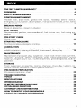
INDEX
THE 1981 ULIMITED WARRANTY"
FOREWORD
0
0
•••••
0
.
•••••••••
SAFETY IN MAINTENANCE ..
0
•
0
••
•
, ..
.
0
• • •
.4
0 . . . . . . . . . . . . . . . . . . . . . . .
•••••
0
2
•••••••••••••••••••••••••••
5
CONTROLS/INSTRUMENTS
Throttle lever, brake
ignition/light switch, headlamp dimmer switch,
emergency cut-out switch,
manual starter handle, primer, tether
cut -out switch. .. .
,... , . . . .
,
, . . ..
6
0
BREAK-IN PERIOD
Break-in, inspection, inspection checklist
FUEL MIXING
Recommended
cedure . . . . . . . . . . . ..
0
0. . . . .
•••
.
08
recommended oil, fuel mixture ratio, fuel mixing pro10
••••••••••••••••
0.
0
•••••
0
••••••••••••••••••••
PRE-START CHECK
Check points
.
•
..11
STARTING PROCEDURE
Starting procedure, emergency starting ..
0
0
•••
0
•••••••
0
••••
0
•••••••••••
LUBRICATION
Frequency, console removal, pulley guard removal, drive belt
wheel suspension, steering mechanism, chaincase oil, drive pulley
•
12
boggie
..... .13
MAINTENANCE
Maintenance chart, spark plug, suspension, track, track tension and alignment,
carburetor, drive belt,
mechanism,
steering adjustment, engine
head nuts, engine mount nuts, muffler attachment, general inspection, bulb re16
o
'0'
• • • • • • • • •
.,
•••••
,
••••••••••
STORAGE
Track, suspension, ski assembly, controls, chaincase, drive pulley, fuel tank, carburetor, cylinder lubrication, chassis,
inspection .....
20
0
PRE-SEASON PREPARATION
Pre-season preparation, chart,
0
0
•••
0
•
•
•
••••
0
0
•
•
TROUBLE SHOOTING .
TOOLS ..
SPECIFICATIONS . . . . . . . .
..........,.....
WIRING DIAGRAM ....
SI METRIC INFORMATION GUIDE
OFTEN ASKED QUESTIONS . . . . .
LISTING OF AREA DISTRIBUTORS . . .
HOW TO IDENTIFY YOUR SNOWMOBILE .
CHANGE OF ADDRESS OR OWNERSHIP . . . .
0
o.
0
•
•
•
•
•
•
•••
0
•••
0
•
••
•
•
•
••
•
•
0
•••
. , .
0
•••
.,
0
•
•
0
•••••••••
0
,
•••
•
0
••
0
0
,
,
o.
•
•
•
•
o.
•
0
0
••
••
0
0
0
••
0
•
•
•
•
•
•
•
•
•
••
0
•••
0
•
•
•
•
•
•
•
•
•
•
•••
0
0
••••••••••
0
0
•••
0
••
•
•
•
•
•
•
0
•
•
•
•
•
•
•
•
0
0
••
••••••
•
••
••••••••••
0
0
0
023
.24
26
27
28
29
30
•••••••••••••••••
0
0
0
•
••••••
0
••
•
•
,
•••
•••
•
•
32
••
0
••••••••••
• • • • • • • • • • • • • • •
,
•
• • • • • • •
33
35
LIMITED WARRANTY 1981 SKI-DOO® SNOWMOBILES
1 - PERIOD
BOMBARDIER Lirnitee as manufacturer, warrants FROM THE DATE OF FIRST
CONSUMER SALES, every 1981 Ski-Doo® snowmobile, sold as NEW AND UNUSED, by an authorized Ski-Doo dealer, for periods of:
ELlTE®, ALPINE®
• 12 months for ELAN® , CITATION*, EVEREST®,
models .
• 90 consecutive days for BLiZZARD® 5500, 7500, 9500 models subject to the
following:
1. If delivery is made after the 31st day of March of a given year and before the 1st
day of December of the same year, the above 90 day warranty will start on December 1st.
2. If delivery is made on/or after the 2nd day of January of a given year but before
the 31st day of March of the same year, all the unused portion of the 90 day period will be carried over to the next winter and start again on the 1st day of
December of the same year.
2 - WHAT BOMBARDIER WILL DO
BOMBARDIER will repair and/or replace, at its option, components defective in
material and/or workmanship (under normal use and service,) with a genuine
BOMBARDIER component without charge for parts or labour, at any authorized
Ski-Doo dealer during said warranty period.
3 - CONDITION TO HAVE WARRANTY WORK PERFORMED
Present to the servicing dealer, the hard copy of the BOMBARDIER Customer Registration card received by the customer from the selling dealer at time of purchase.
4 - WARRANTY TRANSFER
This warranty is transferable to subsequent ownertsl for remainder of warranty period from original date of sale.
5 - EXCLUSIONS - ARE NOT WARRANTED
• Normal wear on all items such as, but not limited to:
- drive belts
slider shoes
spark plugs
- breaker points
runners on skis
• A sulphated battery.
• Replacement parts and/or accessories which are not genuine Bombardier parts
and/or accessories.
• Damage resulting from installation of parts other than genuine BOMBARDIER
parts.
• Damage caused by failure to provide proper maintenance as detailed in the
Operator Manual. The labour, parts and lubricants costs of all maintenance services, including tune-ups and adjustments will be charged to the owner.
2
• Vehicles used for racing purposes.
• All optional accessories installed on the vehicle.
(The normal warranty policy for parts and accessories, if any, applies).
• Damage resulting from accident, fire or other casualty, misuse, abuse or neglect.
• Damage resulting from modification to the snowmobile not approved in writing
by BOMBARDIER.
• Losses incurred by the snowmobile owner other than parts and labour,
such as, but not limited to, transportation, towing, telephone calls, taxis, or
any other incidental or consequential damages.
Some states or provinces do not allow the exclusion or limitation of incidental or
consequential damages, so the above limitation or exclusion may not apply.
6 - EXPRESSED OR IMPLIED WARRANTIES
This warranty gives you specific rights, and you may also have other legal
rights which may vary from state to state, or province to province. Where applicable this warranty is expressly in lieu of all other expressed or implied
warranties of BOMBARDIER, its distributors and the selling dealer, including
any warranty of merchantability of fitness for any particular purpose; otherwise the implied warranty is limited to the duration of this warranty.
However, some states or provinces do not allow limitations on how long an
implied warranty lasts, so the above limitation may not apply.
Neither the distributor, the selling dealer, nor any other person has been
authorized to make any affirmation, representation or warranty other than
those contained in this warranty, and if made, such affirmation, representation or warranty shall not be enforceable against BOMBARDIER or any other
person.
7· CONSUMER ASSISTANCE
If a servicing problem or other difficulty occurs, we suggest the following:
1. Try to resolve the problem at the dealership with the Service Manager or
Owner.
2. If this fails, contact your area distributor listed in the Operator Manual.
3. Then if your grievance still remains unsolved, you may write to us:
BOMBARDIER L1MITEE
Customer Relations
Recreational Product Division
Valcourt, Quebec, Canada, JOE 2LO
BOMBARDIER LIMITEE RESERVES THE RIGHT TO MODIFY ITS WARRANTY POLICY AT ANY TIME, BEING UNDERSTOOD THAT SUCH MODIFICATION WILL NOT ALTER THE WARRANTY CONDITIONS APPLICABLE TO
VEHICLES SOLD WHILE THE ABOVE WARRANTY IS IN EFFECT.
October 1979
Bombardier Limitee
Valcourt, Quebec, Canada, JOE 2LO
®
"Trademarks of Bombardier Limltee
3
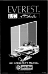
FOREWORD
The operator manual and the Snowmobile Safety handbook have been
prepared to acquaint the owner I operator of a new snowmobile with the various vehicle controls, maintenance and
safe
instructions. Each is indispensable
the proper use of the
product, and should be kept with the
vehicle at all times.
Should you have any questions pertaining to the warranty and its application, please consult the "Often Asked
Question" section of this manual, or
your selling dealer.
4
This manual uses the following symbols.
A
T
WARNING: Identifies and instruction which, if not followed,
could cause personal injury.
. . . CAUTION: Denotes an instruc.... tion which, if not followed, could
severely damage vehicle components.
O
NOTE: Indicates supplementary
information needed to fully coman instruction.
Although the mere reading of such information does not eliminate the hazard, your understanding of the information will promote its correct use.
SAFETY IN MAINTENANCE
Observe the following
precautions:
• Throttle mechanism should be
checked for free movement before
starting engine.
• Engine should be running only when
pulley guard is secured in place.
• Never run engine without drive belt
installed. Running an unloaded encan prove to be dangerous.
• Installation of other than standard
equipment, including ski-spreaders,
bumpers, pack racks, etc.. could
SA\/AnAI\I affect the stability and safety of your vehicle. Avoid adding on
accessories that alter the basic vehicle configuration.
• The snowmobile engine can be
stooced by activating the emergency cut-out switch, tether switch or
by turning off the key.
•
Never run the engine when the track
is raised off the grou nd.
• It can be dangerous to run
with the cab removed.
• Whenever the vehicle is parked outdoors. overnight or for a long
period, it is suggested to protect it
against the inclemency of the
weather with a snowmobile cover.
• Gasoline is flammable and explosive
under certain conditions. Always
manipulate in a well ventilated area.
Do not smoke or allow open flames
or sparks in the vicinity. If gasoline
fumes are noticed while driving; the
cause should be determined and
corrected without delay.
• Do not lubricate throttle and/or
brake cables and housings.
•
Please read and understand all warnings and cautions in this manual and
on the vehicle.
• Maintain your vehicle in top mechanical condition at all times.
• Your snowmobile is not designed to
be driven or operated on black top;
bare earth, or other abrasive surfaces. On such surfaces abnormal
and excessive wear of critical parts
is inevitable.
THIS MANUAL SHOULD REMAIN WITH THE VEHICLE AT THE
TIME OF RESALE.
5
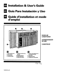
CONTROLS I INSTRUMENTS
AJ
B)
CJ
D)
EJ
FJ
GJ
HJ
I)
Throttle Control Lever
Brake Control Lever
Ignition / Light Switch
Head/amp Dimmer Switch
Emergencv Cut-Out Switch
Decompressor
Manual Starter Handle
Primer
Tether Cut-Out Switch
C) Ignition I Light Switch
OFF
,.,.ON
A) Throttle Control Lever
Located on the right side of the
handlebar. When compressed, it controls the engine speed and the engagement of the transmission. When released, engine speed returns automatically to idle.
B) Brake Control Lever
Located on the left side of the handlebar. When compressed, the brake is
applied. When released, it automatically returns to its original position. Braking effect is proportionate to the pressure applied on the lever.
6
Key operated, 2 position switch. To
start the engine, first turn the key
clockwise to ON position. To stop the
engine, turn the key counter-clockwise
to 0 FF position.
The lights are automatically ON whenever the engine is running.
D) Headlamp Dimmer Switch
Located on left side of handlebar, flick
switch to high or low beam.
E) Emergency Cut-Out Switch
A 3 position switch located on the right
side of the handlebar. To stop the engine in an emergency ,flick the lever to
either upper or lower "OFF" position.
To start engine, lever must be in middle "ON" position.
The driver of this vehicle should
familiarize himself with the function of
this device by using it several times on
the first outing, thereby being mentally
prepared for emergency situations requiring its use.
.... WARNING: If the switch has
~ been used in an emergency situation the source of malfunction should
be determined and corrected before restarting the engine.
f) Decompressor
Two position (OFF / ON), push-pull
knob. To engage, pull the decompressor knob fully out.
. . CAUTION: The decompressor'
•
provides easier starting by reducing engine compression. However,
leaving the decompressor engaged
while running will damage your engine.
Always disengage after the engine has
started.
0) Manual Starter Handle
Auto rewind type located on the right
hand side of vehicle. To engage
mechanism, pull handle.
If emergency engine "shut-off" is required completely pull cap from safety
switch and engine power will automatically shut "off'.
O
NOTE: The cap must be installed
on the safety switch at all times in
order to operate the vehicle .
.... WARNING: If the switch is used
~ in an emergency situation the
source of malfunction should be determined and corrected before restarting engine.
Hood Opening
Unlock latches on both sides where the
hood meets the frame.
NOTE: Always lift the hood gently
up until stopped by the restraining rope.
.... WARNING: It is dangerous to run
~ engine with hood opened, off or
unfastened. Personal injury could result .
O
ToolBox
Located under the hood. To gain access, tilt the hood. Ideal location for
spare plugs, belt, rope, etc.
Fuel Gauge
The tank is translucent and fuel level
can be checked by opening hood and
glancing at tank.
.... WARNING: Never use a lit match
~ or open flame to check fuel level.
H) Primer
A push-pull button. Pull and push button (2-3 times) to activate primer. The
primer should always be used for cold
engine starts. After engine is warm
however, it is not necessary to use. primer when starting.
I)
Tether Cut-Out Switch
Attach tether cord to wrist or other
convenient location then snap tether
cut-out cap over receptacle before
starting engine.
7
BREAK-IN PERIOD
With Bombardier-Rotax snowmobile
engines, a break-in period is required
before funning the vehicle at full throttle. Engine manufacturer recommedation is 10 to 15
hours. During this period, a richer mixture is
needed (i.e. 40 parts of gas for 1 part of
50/1 Bombardier oill. Maximum throttle should not exceed 3/4, however,
brief full acceleration and speed variations contribute to a good break-in.
Continued wide open throttle accelerations, prolonged cruising speeds. and
lugging are detrimental durinq the
break-in period.
O
NOTE: A new drive belt
a break-in period of 15-25 km (1015 miles)
8
10 Hour Inspection
As with any precision piece of mechaical equipment, we suggest that after
the first 10 hours of
or 30
days after the purchase. whichever
comes
that your vehicle be checked by your
This inspection will
give you the opportunity to discuss the
unanswered questions you may have
encountered during the first hours of
operation. Remember that it is easier
to remedy at this time than ~o allow .the
snowmobile to
until a possible
failure occurs.
The 10 hour inspection is at the expense of the vehicle owner.
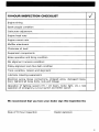
10·HOUR INSPECTION CHECKLIST
Engine timing
Spark plug(s) condition
'"
Carburetor adjustment
Engine head nuts
Engine mount nuts
Muffler attachment
Chaincase oil level
Suspension components
Brake operation and lining condition
Ski alignment (runners condition)
Pulley alignment and drive belt condition
Track condition, tension and alignment
Lubricate (steering suspension)
Electrical wiring (loose connections, stripped wires, damaged insulation). tightend all loose bolts, nuts and linkage
Operation of lighting system (H I / LO beam, brake light, etc.I, test
operation of emergency cut-out switch and tether switch
We recommend that you have your dealer sign this inspection list.
Date of 10 hour inspection
Dealer signature
9
FUEL MIXING
Oil must be added to the gasoline in
pre-measured amounts then both oil
and gasoline should be thoroughly
mixed together before fueling the tank.
Recommended Gasoline
Use regular leaded gasoline available
from an service stations.
. . , CAUTION: Never experiment
... with different fuel or fuel ratios.
Never use naphtha, methanol or similar
products.
Recommended Oil
Use concentrated Bombardier snowmobile oil available from your dealer.
This type of oil has specially formulated oil bases to meet the lubrication requirements of the BombardierRotax engine.
If Bombardier snowmobile 011 is unavailable, substitute with a high-quality
2 cycle snowmobile oil. The oil/gas
mix must meet the vehicle requirements. See oil manufacturer recommendations on the container .
. . , CAUTION: Never use outboard
... or straight mineral oils.
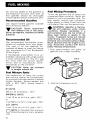
Fuel Mixing Procedure
To mix the gasoline and oil always use
a separate clean container. Never mix
directly in your snowmobile tank. For
best
acquire two containers,
either plastic or metal. Draw from one
until empty then use the second one.
..... WARNING: Gasoline is flammaT ble and explosive under certain
conditions. Always manipulate in a
well ventilated area. Do not smoke or
allow open flames or sparks in the
vicinity. If gasoline fumes are noticed
while driving, the cause should be determined and corrected without delay.
Never add fuel while the engine is running. Avoid skin contact with fuel at
below freezing temperatures.
1. Pour approximately one gallon of
gasoline into a clean container.
Fuel Mixture Ratio
The importance of using the correct
fuel mixture cannot be overstressed.
An incorrect fuel ratio results in serious
engine damage. Recommended fuel
ratio is 50/1 (40/1 during break-in
period)
Sl UNITS
500 mL oil to 25 liters
=
50/1
IMPERIAL UNITS
1 can 16 oz oil to 5 imp. gals 50/1
or
1 can 500 mL oil to 51/2 imp. gals 50/1
U.S. UNITS
1 can 12 oz oil to 5 U.S. gals
O
ture.
10
50/1
NOTE: To facilitate fuel mixing oil
should be kept at room tempera-
2. Add the full amount of oil.
PRE-START CHECK
3. Replace the container cap and
shake the container thoroughly.
Check Points
• Activate the throttle control lever
several times to check that it operates easily and smoothly. The throttle control lever must return to idle
position when released.
• Check fuel level.
• Check that the ski and the tracks are
not frozen to the ground or snow
surface and that the steering operates freely.
•
4. Add the remainder of the gasoline.
5. Once again thoroughly agitate the
containe. Then using a funnel with a
fine mesh screen to prevent the entry of water and foreign particles,
pour the mixture into the snowmobile tank.
Activate the brake control lever and
make sure the brake fully applies before the brake control lever touches
the handlebar qrip.
• Verify that the path ahead of the vehicle is clear of bystanders and
obstacles.
+
W A RN ING: Only start your
snowmobile once all components
are checked and functioning properly.
O
NOTE: When using pre-mixed
fuel, always shake the container
thoroughly as the oil has a tendency to
settle.
+
WARNING: Never 'top up' the
gas tank before placing the vehicle in a warm area. At certain temperatures, gasoline will expand and overflow. Always wipe off any gasoline
spillage from the snowmobile.
11
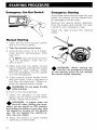
STARTING PROCEDURE
Emergency Cut-Out Switch
Emergency Starting
Should the rewind starter rope fray and
break, the engine can be started with
an emergency starter rope.
Remove the rewind starter assembly
from the engine and transfer the rope
handle to your emergency rope.
Wind the rope around the starting
pulley.
Manual Starting
1. Insert the key in the ignition switch
and turn to ON position.
2. Test the throttle control lever.
3. Activate the primer (2 to 3 times).
(Also pull the decompressor knob
fully out.).
O
NOTE: The use of the primer is
not necessary when the engine is warm.
4. Make sure that the tether cut-out
cap is in position and that the cord is
attached to your clothing. Check
that the emergency cut-out switch
is in the ON position.
5. Grasp manual starter handle firmly
and pull slowly until a resistance is
felt then pull vigorously. Slowly release the rewind starter handle .
WARNING: Do not apply throttle
while starting.
•
6. Push in the decompressor
7. Check the operation of the emergency cut-out switch and the tether
switch. Restart the engine .
WARNING: If engine does not
shut-off when flicking the emer•
gency cut-out switch to OFF position
and pulling the tether cut-out cap, stop
the engine by turning off the ignition
key. Do not operate the vehicle further, see your dealer.
8. Allow the engine to warm before
operating at full throttle.
12
WARNING: When starting the
vehicle in an emergency situation
•
by the starting pulley do not reinstall
the rewind starter assembly.
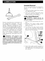
LUBRICATION
Console Removal
For any procedure that may
re·moval of the console, proceed as
follows:
1. Unlock the latch where the console
and dashpanel meet.
2. Push the console downward then
tilt away from the engine. To reinstall, reverse the procedure.
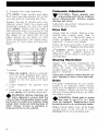
Pulley Guard Removal
...... WARNING: Engine should be
T running only when pulley guard is
secured in place.
Routine maintenance is necessary for
all mechanized products, and the
snowmobile is no
. A weekly
vehicle inspection contributes to the
life span of the snowmobile as well as
retai ns safe and dependable operation.
It is recommended that the steering
system and suspension be lubricated
monthly or every 40 hours of operation. If the vehicle is operated in wet
snow or in severe conditions these
items should be lubricated more frequently .
...... WARNING: Only perform such
T procedures as detailed in this
manual. It is recommended that dealer
assistance be periodically obtained on
other components / systems not covered in this manual. Unless otherwise
.. specified, engine should be turned OFF
for all lubrication and maintenance pro-
1. Tilt the hood and remove the console.
2. Remove the driven pulley guard
(front) by unlocking it from it's attaching points.
3. To remove the drive pulley guard,
pullout the retaining clip (A) and
pull on the spring (B) to disengage
the pin from the bracket.
cedures.
4. Push the pulley guard forward to
disengage the front attachment (C)
from the frame. Lift the guard from
the vehicle.
13
Drive Belt Removal
+
WA RNING: Never start or run
the engine without the drive belt
installed. Running an unloaded engine
is dangerous.
4. Slip the belt out from the drive pulley and remove completely form the
vehicle. To install the drive belt,
reverse the procedure.
1. Tilt the hood and remove the pulley
guard.
2. Open the driven pulley by twisting
and pushing the sliding half. Hold in
fully open position.
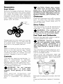
Bogie Wheel Suspension
3. Slip the belt over the top edge of the
sliding half.
Lubricate the suspension bogie wheels
using low temperature grease. Pump
through the grease fitting at the center
of each wheel until new grease appears
at the joint of the inner side of the
shaft.
Lubricate the rear axle with low temperature grease. Pump through the
rear axle fittings .
. . , CAUTION: Always use a low
... pressure grease gun when lubricating rear axle.
14
Steering Mechanism
Drive pulley
..... WARNING: Do not lubricate
throttle and / or brake cable and
housings.
The drive pulley requires lubrication bimonthly or every 20 hours of operation .
..... WARNING: The lubrication of
the drive pulley should be performed only by an authorized dealer. A
disassembly, cleaning, inspection and
lubrication where applicable should
also be performed by the dealer every
50 operating hours or at the end of
each season, whichever occurs first.
T
Lubricate the ski
tings until new
joints. Oil the
at the grease fitappears at the
coupler bolts.
T
Chaincase oil level
Remove the tool box then check the oil
level by removing the oil level inspection plug. Oil should be at the bottom
lip of the hole. Replenish as necessary
by removing the filler cap using a spark
plug socket.
Filler cap
Oil level
Inspection plug
15
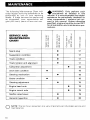
MAINTENANCE
The following Maintenance Chart indicates regular servicing schedules to be
performed by you or your servicing
dealer. If these services are performed
as suggested, your snowmobile will
give you many years of low-cost use.
SERVICE AND
MAINTENANCE
CHART
.&
WARNING: Only perform such
.... procedures as detailed in this
manual. It is recommended that dealer
assistance be periodically obtained on
other components / systems not covered in this manual. Unless otherwise
specified, engine should be turned OFF
for all lubrication and maintenance procedures.
>--
~ E
(1)0
l-LD
(1)0
..... 0
o~
OLD
~E
~~
::
E
:::~
§8
';;:::'00
(1)0
s~
>-
•
•
•
•
Spark plug
Suspension condition
Track condition
Track tension and alignment
Carburetor adjustment
Drive belt condition
•
Steering adjustment
o
16
>-
03 E
ro>~
Q) Q)
g 8
~
o
17
17
17
17
•
18
18
•
18
•
Engine mount nuts
General inspection
l-
m>-~
18
Engine head nuts
Muffler attachment
a
•
Steering mechanism
Brake condition
E
80
>-
03> E
•
•
19
•
•
19
19
19
20
NOTE: The ten hour inspection is a very important part of proper service and
maintenance.
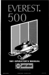
Spark Plug
Track Condition
Disconnect the spark plug wire and remove the spark plug.
Lift the rear of vehicle and support it
off the ground. With the engine off
rotate the track by hand, and inspect.
If worn, cut or the track fiber is exposed or missing or defective inserts or
guides are noted, contact your dealer.
Check condition of plug.
• A brownish tip reflects ideal conditions. (Correct carburetor, spark
plug heat range; etc.).
• A black insulator tip indicates fouling caused by; carburetor idle speed
mixture and / or high speed mixture
too rich, incorrect fuel mixture ratio,
wrong type of spark plug (heat
range), or excessive idling.
• A light grey insulator tip indicates a
lean mixture caused by; carburetor
high speed mixture adjusted too
lean, wrong spark plug heat range,
incorrect fuel mixture ratio, or a
leaking seal or gasket.
Overheated
\light grey)
I
.... WARNING: Do not operate a
T snowmobile with a cut, torn or
damaged track.
Track Tension and
Alignment
Lift the rear of the vehicle and support
it off the ground. Using a rule, check
the track tension from the middle set of
bogie wheels.
The distance between the top inside
edge of the track and the bottom of the
footboard should be 35 mm (1 3/8").
Fouled
(black)
. . . CAUTION: If spark plug condi... tion is not ideal, contact your authorized dealer.
Check the spark plug gap using a wire
feeler gauge.
Reinstall the plug and connect the wire.
Suspension Condition
Visually inspect suspension springs.
Replace any weak or broken spring.
Check for wear or looseness. Correct
as required.
If the track tension is too
the
track will have a tendency to thump. If
too tight, performance will be affected.
If necessary to adjust.
1. Using a wrench loosen both track
adjusters by unscrewing the lock
nuts situated on the inner side of the
suspension springs.
I
2. Adjust to proper tension by turning
adjuster bolts clockwise to tighten
counter-clockwise to slacken. Adjust both side equally.
17
3. Proceed with track alignment.
Carburetor Adjustment
O
. . . CAUTION: Never operate your
.... snowmobile with the air intake silencer disconnected. Serious engine
damage will occur.
NOTE: Track tension and alignment are inter-related. Do not adjust one without checking the other.
Support the rear of vehicle with a mechanical stand. Start the engine and
accelerate slightly so that the track
turns slowly. Check that the track is
well centered and turns evenly on the
rear sprockets. The distance between
the edges of the track and the link
plates should be the same on both
sides. Misalignment can cause excessive wear of track edges and sprocket
teeth.
Carburetor adjustment should be performed by your dealer.
Drive Belt
Inspect belt for cracks, fraying or abnormal wear (uneven wear, wear on
one side, etc.) If abnormal wear is
noted, probable cause is pulley misalignment. Contact your dealer.
Check the drive belt width, if less than
2.7 cm (1 1/16"). Replace the drive belt.
O
NOTE: When installing a new
drive belt,
break-in period of
15-25 km (10-15 miles) is strongly recommended
Steering Mechanism
Equal distance
To adjust:
1. Stop the engine. Using a wrench,
turn the track adjuster bolt clockwise on the side where the track is
closest to the link plate until track
aligns.
2. Firmly retighten the adjuster lock
nuts.
3. Restart the engine and rotate the
track slowly and recheck alignment.
.... WARNING: Before checking the
track alignment, ensure that the
track is free of all particles which could
be thrown out while it is rotating. Keep
hands, feet, tools and clothing clear of
track. Ensure no-one is standing in
close proximity to the vehicle.
T
18
Inspect the steering mechanism for
tightness of components (steering
arms, tie rods, ball joints, spring
coupler bolts, etc.). If necessary, replace or retighten.
Check the condition of skis and ski runners. Replace if worn more than half.
Brake
The brake mechanism on your snowmobile is an essential safety device.
this mechanism in proper working condition. Above all, do not oper- ..
ate your snowmobile without an effective brake
C'\'C'TnrY\
.... WARNING: Brake pad or pucks
less than 5 mm (3/16 in.) thick
must be replaced. Replacement must
be performed by an authorized dealer.
T
Brake should apply fully while brake
control lever is still 2.5 cm (1 inch)
minimum from the handlebar grip.
If a minor adjustment is indicated,
slack off the cable housing nut (AJ and
tighten the nut (B) to increase the lever
clearance.
If necessary to adjust:
Loosen the lock nuts of the longer tie
rod. Turn the tie rod manually until the
skis are properly aligned. Firmly retighten the lock nuts.
Handlebar should also be horizontal
when the skis are pointed toward the
front. To adjust; loosen the lock nuts
of the shorter tie rod. Turn the tie rod
manually until the handlebar is horizontal. Retighten the lock nuts firmly.
Check tightness of the steering arm
locking bolts and the wear of the ball
joints .
Once minor adjustment is completed,
firmly tighten the nuts (A and B)
against the bracket. If correct brake
control lever clearance is unobtainable,
proceed with major adjustment as
follows:
..... WARNING: The cut off section
. . . of the ball joint must run parallel
with the steering arm. When tightening lock nuts, restrain ball joint with appropriate size wrench. Ensure at least
half of the ball joint threads are inserted into the tie rod.
Slacken off the nut retaining the brake
cable to the lower brake lever. Adjust
the cable to required length by lengthening or shortening the brake cable.
Retighten the nut. Ensure that minor
adjustment nuts are located approximately half way on the adjuster
threads.
..... WARNING: Always check the
. . . stop .Iight to see if it functions after performing brake adjustment.
Steering Adjustment
Skis should have a toe out of 3 mm (1/8
in. I. To check measure distance between skis at front and rear of leaf
springs.
I
~
===
==
Incorrect
--:~
Engine Head Nuts
With the engine cold, check that the
engine head nuts are tight and equally
torqued to 22 N.m (16 tt-lbsl
IMPORTANT: The engine head nut
torque should be checked after the first
5 hours of operation.
Engine Mount Nuts
Check the engine mount nuts for tightness. Retighten if necessary.
Muffler Attachment
The engine / muffler attaching parts
are vital toward efficient muffler function. Check all attachments.
and / or tighten if necessary.
19
STORAGE
General Inspection
Check electrical wiring and cOf!1ponents, retighten loose connections.
~heck. for stripped wires or damaged
insulation. Thoroughly inspect the vehicle and tighten loose bolts, nuts and
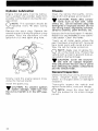
Bulb Replacement
If the headlamp is burnt, tilt hood and
unplug the connector from the headlamp. Remove the rubber boot and unfasten the bulb retainer
Detach
the bulb and
If
taillight
bulb. is burnt, expose the bulb by
moving the red plastic lens. (Two (2)
Phillips head screws). Verify all lights
after replacement.
.... WARNING: Only perform such
T procedures as detailed in this
manual. It is recommended that dealer
assistance be periodically obtained on
other components / systems not covered in this manual. Unless otherwise
specified, engine should be turned OFF
for all lubrication and maintenance procedures.
Track
the track for wear, cuts, missing track guides and broken rods.
Make any necessary replacement.
.... WARNING: Do not operate a
snowmobile with a cut, torn or
damage track.
T
Lift the rear of the vehicle until the
track is clear of the ground, then support it with a brace or trestle. The
snowmobile should be stored in such a
way that the track does not stay in
contact with the ground.
O
NOTE: The track should be rotated periodically (every 40 days).
Do not release track tension .
I
. . CAUTION: To prevent track
. . damage, temperature in the storage area must not exceed 38° C
(lOO°F).
20
Suspension
Bogie Wheels
Remove the bogie wheel sets. Remove
the cross shaft from each
wheel
set. Clean the bogie wheel assembly
and shaft of dirt and rust. Check the
condition of the cross shaft, replace if
worn. Apply a coat of low temperature
grease over the shaft.
. , CAUTION: Plastic alloy compo... nents such as fuel tank, windshield, etc., can be cleaned using mild
detergents or isopropyl alcohol. Do not
use strong soaps, degreasing solvents,
abrasive cleaners, paint thinners, etc.
Chaincase
Drain the chaincase and refill to proper
level. To drain the chaincase remove
the access plug (lower plug) and tilt
vehicle hard left.
Drive Pulley
The drive pulley should be cleaned and
inspected. It also requires lubrication .
. . .WARNING: The lubrication of
.... the drive pulley should be performed only by an authorized dealer.
Fuel Tank and Carburetor
Remove the cap then using a syphon,
remove gasoline from tank.
Grease each set then spray the springs
with metal protector, or wipe with an
oil soaked cloth. Assemble and install
each set in the proper position.
Ski
Wash or brush all dirt or rust accumulation on the skis and springs. Grease
the ski leg
fittings. Check the
condition
skis, ski runners and leaf
springs.
if worn or weak.
Controls
Lubricate the steering mechanism. Inspect all components for tightness,
(spring
bolts, steering arm
locking bolts, tie rods, ball joints, etc.I.
Tighten jf necessary. Oil
joints
of the brake mechanism .
. . . WARNING: Gasoline is flarnma.... ble and explosive under certain
conditions. Always manipulate in a
well ventilated area. Do not smoke or
allow open flames or sparks in the vicinity.
The carburetor must be dried out completely to prevent gum formation during the storage period.
Assure that the carburetor inlet fuel
line is disconnected. Remove the plug
of the float chamber. Drain carburetor
into a container.
. . . WARNING: Do not lubricate
.... throttle and / or brake cable
housing. Avoid getting oil on brake
pads.
Coat electrical connections and
switches with a greaseless metal protector. If unavailable. use petroleum
jelly.
Reinstall the plug and connect the fuel
line.
Check all fuel lines,
if necessa-
ry.
21
Cylinder Lubrication
Chassis
Engine internal
must be lubricated to protect
cylinder walls from
possible rust formation during the storage period.
Clean the vehicle thoroughly, removing all dirt and grease accumulation.
O
NOTE: This operation should be
repeated every 40 days during
storage.
Remove the spark plug. Operate the
rewind starter to bring the piston at top
position. Pour the equivalent of one
spoonful of air into spark plug hole.
. . CAUTION: Plastic alloy cornpo... nents such as fuel tank, windshield, etc., can be cleaned using mild
detergents or isopropyl alcohol. Do not
use strong soaps, degreasing solvents,
abrasive cleaners, paint thinners, etc.
Inspect the hood and repair if needed.
Repair kits are available at your authorized dealer. Clean the frame.
Touch up all metal spots where the
paint has been scratched off. Spray all
bare metal parts with metal protector.
Wax the cab for better protection.
O
NOTE: Apply wax on glossy finish of the hood only. Protect the
vehicle with a cover to prevent dust accumulation during
. . CAUTION: Cover the snowmo... bile with an opaque tarpaulin.
This will prevent the sun rays or grime
from affecting the plastic components
and the vehicle finish.
General Inspection
Slowly crank the engine several times
using the manual starter.
Install the spark plug.
. . CAUTION: To prevent ignition
... system damage, make sure that
the cut-out switch is in the OFF position.
22
Check the electrical wiring and components,
loose connections.
Check for stripped wires or damaged
insulation.
Thoroughly inspect the vehicle and
tighten loose bolts, nuts and linkage .
O
NOTE: Leave the drive belt off
the pulleys for the entire
period.
,JlV"
U\..{V
PRE-SEASON PREPARATION
To simplify the pre-season preparation
we have drawn up a small chart. The
chart indicates servicing points to be
performed by you and your servicing
dealer. If these services are performed
as
your vehicle will
you many hours of fun and low cost
use.
IMPORTANT: Observe all Warnings
and Cautions mentioned throughout
this manual which are pertinent to the
item being checked. When component
conditions seem less than satisfactory
with genuine Bombardier parts
or suitable equivalents.
I
PRE-SEASON
PREPARATION CHART
•
To be performed by dealer.
To be performed by owner.
0
Change spark plug.
0
0
Check chaincase oil level.
•
•
Check pulleys, verify components and
clean. Lubricate.
Check steering alignment and ski runner
condition.
0
Check track tension and alignment.
Lubricate suspension.
a
Inspect drive belt and install.
0
Check throttle cable for damage and
free operation.
a
Inspect brake condition and operation.
Inspect oil seals for possible cuts or leaks.
Set engine timing, if necessary replace
breaker points.
Check electrical wiring (broken wire,
damaged insulation).
Inspect condition of starting rope.
Check tightness of all bolts, nuts and
linkage.
Refill gas tank.
Adjust carburetor.
•a
•
a
~a
•
23
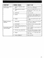
TROUBLE SHOOTING
SYMPTOMS
POSSIBLE CAUSES
WHAT TO DO
Engine turns over but
fails to start or starts
with difficulty
1. No fuel to the engine
Check the tank level and fill up with correct
gas-oil mixture. Check for possible clogging of
fuel line, item 5.
2. Flooded engine
Remove wet spark plug, turn ignition to OFF
and crank engine several times. Install clean
dry spark plug. Start engine following usual
starting procedure. If engine continues to
flood, see your dealer.
3. Spark plug/faulty ignition
Check for fouled or defective spark plug.
Disconnect spark plug wire, unscrew plug
and remove from cylinder head. Reconnect
wire and ground exposed plug on engine
cowl, being careful to hold away from spark
plug hole. Follow engine starting procedure
and check for spark. If no sparks appear, re
place spark plug. If trouble persists.contact
your dealer.
4. Clogged fuel line (water or
dirt)
Check condition and connections of fuel lines.
Check the cleanliness of fuel tank.
5. Incorrect carburetor adjustment
Contact your dealer for repair.
Engine will not turn
manually
24
6. Too much oil in fuel
Drain the fuel tank and refill with the correct
gasloil mixture.
7. Engine timing
Engine timing may be defective or out of adjustment. Contact your dealer.
8. Poor engine compression
Running witha lean fuel mixture may produce
excessive engine wear resulting in poor engine
compression. If this occurs, contact your
dealer at once.
1. Seized engine
In the case of a seized engine contact your
dealer.
SYMPTOMS
POSSIBLE CAUSES
WHAT TO DO
Engine lacks acceleration or power
1. Fouled or defective spark
Check item 3 of "Engine turns over but fails
to start or starts with difficulty"
plug
2. Clogged fuel line (water or
dirt)
Engine continually
backfires
Snowmobile cannot
reach full speed
Check fuel line condition. ISee item 5 of "Engine turns over but fails to start or starts
with difficulty"l.
3. Carburetor
Contact your dealer.
4. Ignition
First check item 2 and 3 of "Engine turns over
but fails to start orstarts with difficulty". If the
ignition system still seems faulty, contact your
dealer.
5. Engine
If unable to locate specific symptoms, contact
your dealer.
1. Spark plug
Check item 3 of "Engine turns over but fails to
start or starts with difficulty".
2. Overheated
Carburetor set too lean. Contact your dealer.
3. Engine timing incorrectly set
Contact your dealer.
1. Drive Belt
Check for damaged or worn drive belt. Replace if necessary.
2. Incorrect track adjustment
Check track tension and alignment. Readjust
to specifications. ISee Maintenance Sactionl
3. Engine
Check item 1 to 5 of "Engine lacks acceler
ation or power.".
4. Pulley misaligned
Contact your dealer.
25
TOOLS
As standard equipment, each new
snowmobile is supplied with a basic
tool kit such as screwdriver, wrenches,
emergency starter rope, etc ..
Standard Tools
A
c
D
A. Screwdriver
B. Socket 21 / 26 mm
C. Socket 10 / 13 mm
D.
Socket handle
E. Angular wrench 10 / 13 mm
F.
26
Starter rope
E
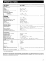
SPECIFICATIONS
1981 ELAN
250 (single)
ENGINE
No. of cylinders
Bore
Stroke
Displacement
Compression ratio (corrected)
Carburetor type
Carburetor adjustment
air screw
idle speed
Engine head nuts (torque)
5:6
Mikuni VM 28-242
1
turn
1100-1300 R.P.M.
N.m (16 ft-lbs)
CHASSIS
Overall length
Overall width
Overall height
Ski stance (center to center)
Ski alignment (toe out)
Weight
Bearing area
Ground pressure
m (88
77,5 em (30112")
1
em (42")
64.8 em (25 112")
3 mm (1/8
129.2
6904
1.813 kPa
11
)
POWER TRAIN
Track dimensions
Track tension
1 em (15") x
35 mm - 3 (1
Track alignment
Std. gear ratio
Chaincase oil capacity
Drive belt (minimum width)
200 mL (7 oz.l
2.7 em (1
in.)
118")
between top
and the bottom of the footboard
distance between
of tracks and link
of
ELECTRICAL
Lighting system (output)
Headlarnp bulb
Tail/stop light
Spark plug (Bosch)
Breaker point gap
Spark plug (gap)
Advanced ignition timing
12
75/23 W
W
M-175 T-1 (M7A)
0,35 0040 mm (,014"
0.50 mm (,020
.016")
fl
)
3,73-4,24 mm (,147"
167") B,T.D.C. (direct)
FUEL
Tank capacity -
S.I.*
Imp.
- U.S.
Gasoline
Gas/oil ratio
BRAKE
Brake type
Brake adjustment (control level)
Brake shoe (minimum thickness)
Drum
(1") minimum distance from handlebar grip when tulIyapplied
5 mm
in.l
2.5
* International Standard
Bombardier Limitee reserves the right to make changes in design and specifications and/or to make additions to, or improvements in its product without imposing any obligation upon itself to install them on
its product previously manufactured.
27
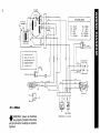
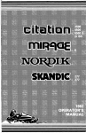
N
MAGNETO
00
COLOUR CODE
~
~
BK
WH
OR/WH
Q.!U.BK
BLACK
WHITE
GN
GY
RD - RED
~
GREEN
GREY
VI- ViOLET
OR - ORANGE
SR
BROWN
Bl - BLUE
Yl
YELLOW
.E:!.!5.
IGNITlON COIL'
BK
I
I
VI
GN/BK
CD
CD
CD
o
®
LIGHTING COIL 175 WI
J:
BRAKE LIGHT COIL (23 W)
~
BRAKE LIGHT SWITCH
~
~
~
c:l
WH
--:::l-
BK
BK
___
VI
OR/BK
0
GYIVI
OR/WH
®~~DYL
TAILLIGHT
:.::
~
o
HEADlAMP 60/60 W
TAILLAMP (5-21 WI
115
;;:
IGNITION GENERATOR COIL
,
I
YL
wH--ri~l
[2 31)_BK
BR-iI
247 cc SINGLE
.& WARNING:
Ensure all terminals
.... are properly crimped on the wires
and all connector housings are properly
fastened.
OFF ON OFF
DIMMER SWITCH
KILL SWITCH
IGNITION SWITCH
,i
Ii
51* METRIC INFORMATION GUIDE
BASE UNITS
DESCRIPTION
UNIT
SYMBOL
length
mass
liquid
temperature
pressure
torque
meter
kilogram
liter
celsius
speed
kilometer per hour
m
L
°C
kPa
Newton meter
N-m
km/h
PREFIXES
PREFIX
kilo
centi
milli
SYMBOL
MEANING
VALUE
k
one thousand
one hundredth of a
one thousandth of a
1
0.01
0.001
c
m
*THE INTERNATIONAL SYSTEM OF UNITS (SYSTEME INTERNATIONAL)
ABREVIATES "Si" IN ALL LANGUAGES.
29
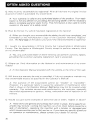
OFTEN ASKED QUESTIONS
Q: Why must my snowmobile be registered? After all I do have my original invoice
as proof of when I purchased my snowmobile.
A: Your warranty is valid at any authorized dealer of the product. Your
tration is the key element in providing the servicing dealer with the necessary
data to complete warranty claim forms. This information is also used to notify
owners in the event of a safety recall.
Q: How do I know my vehicle has been
FonllC't,ClForl
at the factory?
A: When you bought
the dealer should have
and
forwarded us the manufacturer's copy of the Customer Warranty Registration. The hard copy of the card is
that the snowmobile is reotsterea.
Q: I
my snowmobile in 0'
County but I snowmobile in Washington
County. Can the dealer in \/\/:::lC:rlJnl""ltrin County accept to
warranty work
on my snowmobile?
A:
any authorized dealer in North America can
warranty
providing the customer warranty
card is oresentett
Iv~'UII'u.
Q: Where can l find information on the lubrication and maintenance of my snowmobile?
A: In this
JJ.Y':Y..J(,[l[(Jr
Manual
nrovtaeo
with the vehicle at the time of first sale.
Q: Will the entire warranty be void or cancelled, if I do not operate or maintain my
new snowmobile
as specified in the
Manual?
A: The warranty of the snowmobile cannot be "Voided" or "Cencelled".
if a
failure is caused by
or maintenance other
than is shown in the
that failure may not be covered under
warranty. This includes service work
by the customer, especially
the critical
to
timing, carburetion and oil
ad
mixture.
Q: Would you
some
r.v·..,mnlr\C'
of abnormal use or strain "'I"'\'...
I
l n '....1-
or abuse?
A:
terms are general and overlap each other in areas. Some specific examples may include: running the machine out of oil, chain failure caused by a
lack of lubrication, operating the machine with a broken or damaged part
which causes another part to fail, and so on. If you have any specific questions
on operation or maintenance, please contact your dealer for advice.
30
Q: What costs are my responsibility during the warranty period?
A: The customer's responsibility includes all costs of normal maintenance sernon-warranty
accidents and collision
as well as
and
Q: Are "Genuine" Bombardier replacement parts used in warranty
by warranty?
covered
A: Yes. When installed by an authorized
any
Bombardier
part used in warranty
assumes the rarnsnrurtrt warranty that
on
the machine.
Q: What is Bombardier's
a
A: It is not Bombardier's
to extend warranty. Bombardier has selected a
warranty
to
use of the mechine to
allow for concealed menurectunna defects to occur.
Q: Manufacturer does not accept warranty work on seized, scored or melted
why?
fat/ures can
be
A: From
and exoenence we know that such
which are directly related to the follow..
caused
detonation or
ing factors and
are beyond the manufacturer's control.
thL)YDtnYD
•
•
•
•
mixture (too little or too much oil).
Poor
outboard or
mineral oils.
Removal of intake silencer.
Hot
plug (s)
heat
Q: If I sell my snowmobile within the warranty period, will the new owner qualify
for the balance of the warranty?
A: Yes, provided the unit has already been registered with the manufacturer.
Note that the change of ownership card in this manual should be completed
and sent to Bombardier Limitee.
31
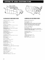
LISTING OF AREA DISTRIBUTORS
CANADIAN DISTRIBUTORS
AMERICAN DISTRIBUTORS
LIMITED
N:;~~~~~:~~i~~a~J~~;hJ~~r~~:~:
P,
"'P'.M '"''''''''\I
Connecticut, Rhode Island,
Maryland, Delaware, District of
Ohio.
DISTRIBUTICIN DIVISION
lAl
BOMBARDIER LIMITE:!:
DISTRIBUTION DIVISION
"V"JU1Lr'\i".'
MJl,CHINF:S INC
03584
Franklin District & Keewatin
32
HOW TO IDENTIFY YOUR SNOWMOBILE
The main components of your snowmobile (engine, track and frame) are
identified by different serial numbers. It
may sometimes become necessary to
locate these numbers for warranty purposes or to trace your snowmobile in
the event of theft.
ENGINE
SERIAL
NUMBER
TRACK
SERIAL
NUMBER
NOTE: We strongly recommend that you take note of all the serial numbers
on your vehicle and supply them to your insurance company. It will surely
help in the event a snowmobile is stolen.
33
NOTES
NOTES
NOTES
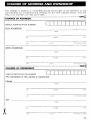
CHANGE OF ADDRESS AND OWNERSHIP
Any change in address or ownership should be brought to the attention of the
manufacturer by completing and sending out the card supplied below. This will
help us to maintain our files up-to-date .
~
: CHANGE OF ADDRESS
...
: VEHICLE IDENTIFICATION NUMBER
: OLD ADDRESS:
·
·
NAME
··
···
. -----------------------------: NEW ADDRESS:
··
···
··
NO
ZIP I
CITY
NAME
NO
··
:
ZIP I POST AL CODE
CITY
~
: CHANGE OF OWNERSHIP
:-----------------------------: VEHICLE IDENTIFICATION NUMBER
: The ownership of this vehicle is transferred
: FROM:
·
··
····
··
··: TO:
_
NAME
NO
STREET
APT
CITY
NAME
NO
APT.
CITY
35
................................................................................:
···
··
···
···
BOMBARDIER LIMITEE
ATT.: WARRANTY DEPARTMENT
·
VALCQURT,QUEBEC
····
CANADA, JOE 2LO
···
···
···
··
..................................................................................···
···
··
BOMBARDIER LIMITEE
ATT.: WARRANTY DEPARTMENT
VALCQURT,QUEBEC
CANADA, JOE 2LO
36
··
··
·
·
··
····
·