1
model
V.I.N.
purchase date
_
warranty expiry date
To be completed by dealer at time of sale.
DEALER IMPRINT AREA
TECHNICAL PUBLICATIONS
AFTER SALES SERVICE DEPARTMENT
BOMBARDIER L1MITEE
VALCOURT,OUEBEC
CANADA, JOE 2LO
The following are trademarks of Bombardier Limitee.
BOMBARDIER EVEREST
SKI-DOO
CITATION
ALPINE
OLYMPIOUE
BLIZZARD
TNT
CARRY-BOOSE
ELAN
ELITE
GRAND PRIX SPECIAL
MOTO-SKI
FUTURA
SPIRIT
NUVIK
MIRAGE
SUPER SONIC
ULTRA SONIC
INDEX
2
3
4
6
8
9
FOREWORD
SAFETY IN MAINTENANCE "
THE 1981 "LIMITED WARRANTY" . . . . .. .. .
OFTEN ASKED QUESTIONS
LISTING OF AREA DISTRIBUTORS
HOW TO IDENTIFY YOUR SNOWMOBILE . .
CONTROLS/INSTRUMENTS
Throttle lever, brake lever, ignition switch, light switch, high beam indicator,
emergency cut-out switch, headlamp dimmer switch, rewind starter, primer, tachometer, speedometer, temperature gauge, tether cut-out switch, adjustable
10
steering handle, mirror, hood opening, tool box, fuel gauge, fuse holder
BREAK-IN PERIOD
Inspection, inspection checklist
14
FUEL
Recommended gasoline, recommended injection oil
16
PRE·START CHECK
Check poi nts . . . . . . . . . . . . . . . . . . . . . . . . . . . . . . . . ..
.
16
STARTING PROCEDURE. . . . . . . . . . . . . . . . . . . . .. ..
.
EMERGENCY STARTING
17
17
DRIVE BELT AND GUARD REMOVAL . . . . . . . . . . . . ..
.. .
18
LUBRICATION
Steering mechanism, chaincase oil level, suspension, rotary valve system, injection oil system
,
.. .19
MAINTENANCE
Spark pluqs, battery suspension condition track, suspension adjustment, track
tension and alignment, carburetor adjustment, drive belt, steering mechanism,
brake, steering, engine head nuts, engine mount nuts, exhaust system, cooling
20
system, general inspection, bulb replacement
I
I
STORAGE
Cooling system, track, suspension, ski assembly, fuel tank, carburetor, cylinder
lubrication, drive pulley, chaincase, controls, battery, chassis, general inspection
27
PRE·SEASON PREPARATION
Pre-season preparation chart . . . . . . . ..
TROUBLE SHOOTING GUIDE
TOOLS
SPECIFICATIONS
WIRING DIAGRAM
SI METRIC INFORMATION GUIDE
CHANGE OF ADDRESS OR OWNERSHIP
.
30
31
33
34
35
36
37
FOREWORD
The Operator Manual and the Snowmobile Safety handbook have been
prepared to acquaint the owner / operator of a new snowmobile with the various vehicle controls maintenance and
safe operating instructions. Each is
indispensable for the proper use of the
product, and should be kept with the
vehicle at all times.
Should you have any
pertaining to the warranty and its application, please consult the "Often Asked
Question" section of this manual, or
your
dealer.
2
This manual uses the following symbols:
. . . WARNING: Identifies an instruc~ tion which, if not followed, could
cause personal injury.
. . , CAUTION: Denotes an instruc. . tion which, if not followed, could
severely damage vehicle components.
O
NOTE: Indicates supplementary
information needed to fully coman instruction.
Although the mere reading of such information does not eliminate the hazard, your understanding of the infor-.
mation will promote its correct use.
SAFETY IN MAINTENANCE
Observe the following
precautions:
• Installation of other than standard
equipment, including ski-spreaders,
bumpers,
racks, etc. could
severely
the stability and safety of your vehicle. Avoid adding on
accessories that alter the basic vehicle configuration.
I
• Throttle mechanism should be
checked for free movement before
starting engine.
• The snowmobile engine can be
stopped by activati ng the emergency cut-out or tether switches or turning off the key.
•
Engine should be running only when
pulley guard is secured in place.
• Never run the engine without drive
belt installed. Running an unloaded
engine can prove to be dangerous.
• Never run the
when the track
is raised off the ground.
• Whenever the vehicle is parked outdoors, overnight or for a long period, it is suggested to protect it
against the inclemency of the
wheather with a snowmobile cover.
• Do not lubricate throttle and/or
brake cables and housings.
Please read and understand all other
warnings contained elsewhere.
• It can be dangerous to run engine
with the cab removed.
• Gasoline is flammable and explosive
under certain conditions. Always
manipulate in a well ventilated area.
Do not smoke or allow open flames
or sparks in the vicinity. If gasoline
fumes are noticed while driving, the
cause should be determined and
corrected without delay.
• Maintain your vehicle in top mechanical condition at all times.
• Your snowmobile is not designed to
be driven or
on black top,
bare earth, or other abrasive surfaces. On such surfaces abnormal
and excessive wear of critical parts
is inevita ble.
THIS MANUAL SHOULD REMAIN WITH THE VEHICLE AT
THE TIME OF RESALE.
3
LIMITED WARRANTY 1981
SKI·DOO~)
SNOWMOBILES
1 . PERIOD
BOMBARDIER Limitee as manufacturer, warrants FROM THE DATE OF FIRST
CONSUMER SALES, every 1981 Ski-Doo® snowmobile, sold as NEW AND UNUSED, by an authorized Ski-Doo dealer, for periods of:
• 12 consecutive months for ELAN® , CITATION*, EVEREST®,
ALPINE® models.
ELlTE®
• 90 consecutive days for BLIZZARD® 5500, 7500, 9500 models subject to the
following:
1. If delivery is made after the 31st day of March of a given year and before the 1st
day of December of the same year, the above 90 day warranty will start on December 1st.
2. If delivery is made on/or after the 2nd day of January of a given year but before
the 31st day of March of the same year, all the unused portion of the 90 day period will be carried over to the next winter and start again on the 1st day of
December of the same year.
2· WHAT BOMBARDIER WILL DO
BOMBARDIER will repair and/or replace, at its option, components defective in
material and/or workmanship (under normal use and service,) with a genuine
BOMBARDIER component without charge for parts or labour, at any authofized
Ski-Doo dealer during said warranty period.
3 - CONDITION TO HAVE WARRANTY WORK PERFORMED
Present to the servicing dealer, the hard copy of the BOMBARDIER Customer Registration card received by the customer from the selling dealer at time of purchase.
4· WARRANTY TRANSFER
This warranty is transferable to subsequent ownerts) for remainder of warranty period from original date of sale.
6· EXCLUSIONS - ARE NOT WARRANTED
• Normal wear on all items such as, but not limited to:
- drive belts
- slider shoes
spark plugs
- breaker points
- runners on skis
• A sulphated battery.
• Replacement parts and/or accessories which are not genuine Bombardier parts
and/or accessories.
•
Damage resulting from installation of parts other than genuine BOMBARDIER
parts.
• Damage caused by failure to provide proper maintenance as detailed in the
Operator Manual. The labour, parts and lubricants costs of all maintenance services, including tune-ups and adjustments will be charged to the owner.
4
• Vehicles used for racing purposes.
• All optional accessories installed on the vehicle.
(The normal warranty policy for parts and accessories, if any, applies).
• Damage resulting from accident, fire or other casualty, misuse, abuse or neglect.
• Damage resulting from modification to the snowmobile not approved in writing
by BOMBARDIER.
• Losses incurred by the snowmobile owner other than parts and labour,
such as, but not limited to, transportation, towing, telephone calls, taxis, or
any other incidental or consequential damages.
Some states or provinces do not allow the exclusion or limitation of incidental or consequential damages, so the above limitation or exclusion may not
apply.
I .. EXPRESSED OR IMPLIED WARRANTIES
This warranty gives you specific rights, and you may also have other legal
rights which may vary from state to state, or province to province. Where applicable this warranty is expressly in lieu of all other expressed or implied
warranties of BOMBARDIER, its distributors and the selling dealer, including
any warranty of merchantability of fitness for any particular purpose; otherwise the implied warranty is limited to the duration of this warranty.
However, some states or provinces do not allow limitations on how long.an
implied warranty lasts, so the above limitation may not apply.
Neither the distributor, the selling dealer, nor any other person has been
authorized to make any affirmation, representation or warranty other than
those contained in this warranty, and if made, such affirmation, representation or warranty shall not be enforceable against BOMBARDIER or any other
person.
7 .. CONSUMER ASSISTANCE
If a servicing problem or other difficulty occurs, we suggest the following:
1. Try to resolve the problem at the dealership with the Service Manager or
Owner.
2. If this fails, contact your area distributor listed in the Operator Manual.
3. Then if your grievance still remains unsolved, you may write to us:
BOMBARDIER L1MITEE
Customer Relations
Recreational Products
Valcourt, Quebec, Canada, JOE 2LO
BOMBARDIER LIMITEE RESERVES THE RIGHT TO MODIFY ITS WARRANTY POLICY AT ANY TIME, BEING UNDERSTOOD THAT SUCH MODIFICATION WILL NOT ALTER THE WARRANTY CONDITIONS APPLICABLE TO
VEHICLES SOLD WHILE THE ABOVE WARRANTY IS IN EFFECT.
October 1979
Bombardier Limitee
Valcourt, Quebec, Canada, JOE 2LO
"Trademarks of Bombardier l.irnitee
5
OFTEN ASKED QUESTIONS
Q: Why must my snowmobile be registered? After alii do have my original invoice
as proof of when I purchased my snowmobile.
A: The information provided by the Customer Warranty Registration card is
computerized, and a/l warranty claims thereafter, are processed by the computer. Without this valuable information on the Warranty Registration Card,
we cannot acknowledge warranty or notify owners of a possible safety recall.
Q: How do I know my vehicle has been registered at the factory?
A: When you bought your snowmobile the dealer should have completed, and
forwarded us the manufacturer's copy of the Customer Warranty Registration. The hard copy of the card is your proof that the snowmobile is registered.
Q: I bought my snowmobile in O'King County but I snowmobile in Washington
County. Can the dealer in Washington County accept warranty work on my
snowmobile?
A: Yes, any authorized dealer in North America can perform warranty repairs,
providing the customer warranty registration card is presented.
Q: Where can I find information on the lubrication and maintenance of my snowmobile?
A: In this Operator Manual provided with the vehicle at the time of first sale.
Q: Will the entire warranty be void or cancelled, if I do not operate or maintain my
new snowmobile exactly as specified in the Operator's Manual?
A: Your warranty is valid at any authorized dealer of the product. Your registration is the key element in providing the servicing dealer with the necessary
data to complete warranty claim forms. This information is also used to notify
owners in the event of a safety recall.
Q: Would you give some examples of abnormal use or strain, neglect or abuse?
A: These terms are
overlap each other in areas. Some
examples may include: running the machine out of oil, chain failure caused by a
lack of lubrication, operating the machine with a broken or damaged part
which causes another part to fail, and so on. If you have any specific questions
on operation or maintenance, please contact your dealer for advice.
6
Q: What costs are my responsibility during the warranty period?
A: The customer's responstbilitv includes all costs of normal maintenance services/ non-warranty repairs, accidents and collision damage/ as well as oils,
and spark plugs/ and incidental or consequential damages costs as explained
in the warranty.
Q: Are "Genuine" Bombardier replacement parts used in warranty repairs covered
by warranty?
A. Yes. When installed by an authorized dealer, any "qenuine" Bombardier
part used in warranty
assumes the remaining warranty that exists on
the machine.
Q: Manufacturer does not accept warranty work on
scored or melted
pistons, why?
A: From testing and experience/ we know that such piston faNures can only be
caused by detonation or pre-ignition, which are directly related to the fa/lowing factors and therefore, are beyond the manufacturer's control.
•
•
•
•
Incorrect oil/gas mixture (too little or too much oil).
Poor quality, outboard or straight mineral oils.
Removal of intake silencer.
Hot spark pluqts) (improper heat range).
Q: If I sell my snowmobile within the warranty period, will the new owner qualify
for the balance of the warranty?
A: Yes, provided the unit has already been registered with the manufacturer.
Note that the change of ownership card in this manual should be completed
and sent to Bombardier i.imitee.
7
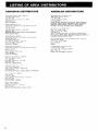
LISTING OF AREA DISTRIBUTORS
CANADIAN DISTRIBUTORS
I\LF)INI~ DISTRIElllTORS LIMITED
AMERICAN DISTRIBUTORS
BOMBARDIER CORPORATION
4505 West Superior Street
P,O, Box 6106
VlT 6M2
Duluth, Minnesota 55806
(218) 628-2881
DISTRIBUTICIN DIVISION
North Dakota, Minnesota, Wisconsin, Illinois, Missouri,
Michigan, Indiana, Ohio (less eastern half), Tennessee,
Kentucky, West Virginia, Virginia, Northern Idaho,
Northern Wyoming, Montana, Iowa, Washington
Maseachusetts, Connecticut, Rhode Island,
Pennsylvania,
Maryland, Delaware, District of
Ohio.
DISTRllBUTIOiN DIVISION
AND RECREATIONAL
IIVI("E:I'tLM"LJ
I nl,DUI lUI'
MACHINE,S INC
DIVISION
Vermont
LTD,
M4W lAB
Franklin District E:t Keewatin
8
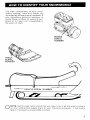
HOW TO IDENTIFY YOUR SNOWMOBILE
The main components of your snowmobile (engine, track and frame) are
identified by different serial numbers. It
may sometimes become necessary to
locate these numbers for warranty purposes or to trace your snowmobile in
the event of theft.
ENGINE
SERIAL
NUMBER
O
NOTE: We strongly recommend that you take note of all the serial numbers
on your vehicle and supply them to your insurance company. It will surely
help in the event a snowmobile is stolen.
9
A)
BJ
CJ
DJ
EJ
FJ
GJ
HJ
Throttle Lever
Brake Lever
Ignition Switch
Light Switch
High Beam Indicator
Emergencv Cut-Out Switch
Headlamp Dimmer Switch
Rewind Starter Handle
A) Throttle Lever
Located on right side of handlebar.
When compressed, it controls the engine speed and the engagement of the
transmission. When released, engine
speed returns automaticalfy to idle.
B) Brake Lever
Located on the left side of handlebar.
When compressed, the brake is applied. When released, it automatically
returns to its original position. Braking
effect is proportionate to the pressure
applied on the lever.
O
NOTE:Compressing the brake
lever will light up the injection oil
level indicator bulb. If bulbs does not
light up, replace with a new one.
10
I}
J)
K)
L)
M)
N)
0)
P)
Primer
Tachometer
Speedometer
Temperature Gauge
Tether Cut -out Switch
Injection oil level indicator
Mirror
Adjustable steering handle
C) Ignition Switch
OFF
START
Key operated, 3 position switch . To
start engine, turn key fully clockwise to
5T ART position and hold. Return key
to ON position immediately after
engine has started. To stop engine,
turn key counter clockwise to 0 FF
position
D) Light Switch
I) Primer
A push pull switch type, to illuminate
headlamp and taillight, pull switch
knob. (Ignition switch must be turned
to ON position).
A push-pull button located alongside
manual starter handle. Pull and push
button (2-3 times) to activate primer.
The primer should always be used for
cold engine starts. After engine is
warm however, it is not necessary to
use primer when starting.
E) High Beam Indicator
Lights up when headlamp is on high
beam.
F) Emergency Cut-Out Switch
A 3 position switch located on the right
side of the handlebar. To stop the
engine in an emergency, flick the lever
jo either upper or lower "OFF" position. To start engine, lever must be
middle "ON" position.
J) Tachometer
The tachometer registers the impulses
of magneto. Direct-reading dial indicates the number of revolutions per
minute (RPM) of the engine.
. . . CAUTION: The tachometer is
... protected bya fuse, if tachometer stops operating check fuse condition and if necessary replace. The fuse
is 0.1 amp. Do not use a higher rated
fuse as this can cause severe damage
to the tachometer.
The driver of this vehicle should familiarize himself with the function of this
device by using it several times on first
outing. Thereby being mentally prepared for emergency situations requiring
its use.
K) Speedometer
..... WARNING: If the switch has
.... been used in an emergency situation the source of malfunction should
be determined and corrected before restarting engine.
The speedometer is linked directly to
the drive axle. Direct-reading dial indicates the speed of the vehicle. Odometer records the total distance travelled.
G) Headlamp Dimmer Switch
U Temperature Gauge
The dimmer switch, located on left side of handlebar, allows; correct selection of headlamp beam. To obtain high
or low beam simply flick the switch.
H) Rewind Starter Handle
Auto rewind type located on right hand
side of vehicle. To engage mechanism,
pull handle.
The gauge indicates engine coolant
temperature. Normal operating temperature is 50°C (120°FL However,
coolant temperature can vary depending on driving condition. If coolant
temperature exceeds 95°C (200°F) reduce speed and run vehicle in loose
snow or stop engine immediately.
..... WARNING: To remove coolant
.... tank cap, place a cloth over the
cap and unscrew it to the first step to
release the pressureo If this notice is
disregarded loss of fluid and possible
severe burns cou Id occu r.
11
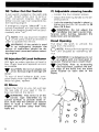
M) Tether Cut-Out Switch
P) Adjustable steering handle
A pull switch located on the right side
of cab. Attach tether cord to wrist or
other convenient location then snap
tether cut-out cap over receptacle before starting engine.
- Adjust the steering handle to the desired position.
If emergency engine "shut off" is required completely pull cap from safety
switch and engine power will be automatica Ily shut r off" .
t
O
NOTE: The cap must be installed
on the safety switch at all times in
order to operate the vehicle.
•
WARNING: If the switch is used
..... in an emergency situation the
source of malfuntion should be determined and corrected before restarting engine.
N) Injection Oil Level Indicator
WlIl light up when injection oil level is
low. Check level and replenish as soon
as possible.
. . CAUTION: Do not run engine out
•
of oil. Serious engine damage will
occur.
To test oil level indicator bulb, compress brake lever (ignition ON). If light
does not glow r replace.
- Loosen the four retainer screws.
Lock the steering handle in place by
tightening the four (4) screws to 26
N-m (19 ft-lbsl,
•
WARNING: Do not adjust the
..... handlebar too high to avoid interference when turning, between the
brake lever and windshield.
Hood Opening
Pull down the latch to unhook the
hood from the anchor .
NOTE: Always lift hood gently up
until stopped by restraining device .
O
•
WARNING: It is dangerous to run
..... an engine with the hood open or
removed. Personal injury could result.
. . CAUTION: Prior to re-securing
•
the hood latch, position the bottom edge of the hood into the hood
guide located on each side of the
frame.
0) Mirror
Adjust the mirror so you can just see
the rear side of your seat in the inboard portion of the mirror.
•
WARNING: This mirror is of the
.....convex type (identified by its
curved surface) to provide wider vision. Note that the vehicles or objects
seen in such a mirror will appear
smaller and farther away than they
really are.
0
0
0
0
o
12
0
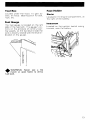
ToolBox
Fuse Holder
Located under the hood. To gain access, tilt hood. Ideal location for belt,
rope, etc.
Starter
Located in the engine compartment, at
the right of the battery.
Fuel Gauge
The fuel gauge is located on the left
side of the fuel tank. The gauge f~nc
tions on the principle of con:m~nlcat
ing vessels, so the fuel I.evel inside t.he
tank is directly related with the level indicated on the gauge .
Instrument
Located on the ignition switch wiring
near the battery.
.... WARNING: Never use a lite
. . . match or open flame to check
fuel level.
13
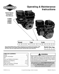
BREAK-IN PERIOD
With Bombardier-Rotax snowmobile
engines, a break-in pe.riod is required
before running the vehicle at full throttle. Engine's manufacturer recommendation is 10 to 15 operating hours. During this period, maximum throttle
should not exceed 3/4, however, brief
full acceleration and speed variations
contribute to a good break-in. Continued wide open throttle accelerations, prolonged cruising speeds, and
lugging are detrimental during the
break-in period.
a
NOTE: For the break-in period
only, 1 (16 oz) can of Bombardier
50/1 engine oil should be added to t.he
first full fuel tank filling, at a 70/1 ratio.
This will assure additionnal protection
during the initial
break-in .
. . CAUTION: Remove and clean
•
spark plugs after engine break-in.
a
NOTE: A new drive belt requires
a break-in period of 15-25 km (1015 miles).
14
10-Hour Inspection
As with any precision piece of mechanical equipernent, we suggest that after
the first 10 hours of operation or 30
days after the purchase, whichever
comes first, your vehicle be checked
by your dealer. This inspection will give
you the opportunity to discuss the unanswered questions you may have encountered during the first hours of
operation. Remember that it is easier
to remedy at this time than to allow the
snowmobile to operate until a possible
failure occurs.
The 10 hours inspection is at the expense of the vehicle owner.
10-HOUR INSPECTION CHECK LIST
I
Engine timing
Spark plug(s) condition: Remove and clean
Carburetor adjustment
Engine head nuts
Engine mount nuts
Muffler attachment
Chaincase, rotary valve and injection oil level
Coolant level
Battery electrolyte level
Brake operation and lining condition
Skis alignment (runnerscondition)
Pulley alignment and drive belt condition
Oil injection pump adjustment
Track condition, tension and alignment
Lubrication (steering, suspension)
Electrical wiring (loose connections, stripped wires, damaged insulation), tighten all loose bolts, nuts and linkage
Operation of lighting system (HI / LO beam, brake light, etc.), test
operation of emergency cut-out switch and tether cut-out switch
We recommend that you have your dealer sign this inspection.
Date of 10 hour inspection
Dealer signature
15
FUEL
PRE-START CHECK
e
Recommended Gasoline
Check Points
Use regular leaded gasoline available
from all service stations.
. . CAUTION: Never experiment
'Y with different fuel or fuel ratios.
Never use naphtha, methanol or similar
products.
•
Activate the throttle control lever
several times to check that it operates
and smoothly. The throttle
lever must return to idle
position when released.
•
Check that the skis and the track are
not frozen to the ground or snow
surface and that
operates
freely.
O
NOTE: For the break-in period
only, 1 (16 oz) can of Bombardier
snowmovile oil should be added to the
first full fuel tank filling, at a 70/1 ratio.
This will assure additional protection
during the initial
break-in.
A. WARNING: Never "top up" the
T gas tank before placing the vehicle in a warm area. At certain temperatures, gasoline will expand and overflow.
Recommended Injection Oil
Use concentrated Bombardier snowmobile oil available from your dealer.
16
• Activate the brake control lever and
make sure the brake fully applies before the brake control lever touches
the handlebar
• Check coolant level.
•
Check fuel level.
•
Check injection oil level
• Verify that the path ahead of the vehicle is clear of bystanders and
obstacles.
A. WARNING: Only start your
T snowmobile once all components
are checked and functioning properly.
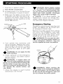
STARTING PROCEDURE
1. Insert key in ignition switch.
2. Test throttle control lever.
3. Activate primer (2 or 3 times) .Primer
is not necessary if engine is warm.
4. Make sure the tether cut-out cap is
in position and that the cord is attached to you r body. Check that the
emergency cut-out switch is in the
center ON position.
. . . CAUTION: Since engine cooling
•
is in effect only when the vehicle
is in motion, it is recommended that
you do not allow the engine to idle for
more than brief periods. Prolonged
idling may cause engine damage.
O
NOTE: If for some reasons, the
vehicle cannot be started electrically, place ignition key to ON position and start engine manually.
Emergency Starting
Should the rewind starter rope fray and
break, the engine can be started with
an emergency starter rope.
Remove the pulley guard from vehicle
and wind the emergency rope tight
around the drive pulley between the
sliding half and the roller guard. Start
engine as per usual manual
OFF
5. Turn ignition
clockwise until
starter engages.
key immediately engine has started. If
does not start on first
must
be turned fully back to
each
time .
..... WARNING: Do not apply throttle
T while starting.
..... WARNING: Do not start the vehicle by the drive pulley unless it is
a true emergency situation, have the
vehicle repaired as soon as possible.
T
/
6. Check operation of the emergency
cut-out
and tether switch.
Restart engine .
..... WARNING: If engine does not
shut-off when applying the emergency cut-out switch and or when pulling the tether cut-out cap, stop the engine by turning off the ignition key. Do
not operate the vehicle further, see
you r dealer.
T
7. Allow the engine to warm before
operating at full throttle.
..... WARNING: When starting the
T vehicle in an emergency situation
by the drive pulley, do not make a knot
at the end of the emergency rope and
do not reinstall the pulley guard.
17
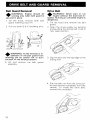
DRIVE BELT AND GUARD REMOVAL
Belt Guard Removal
Drive Belt
. . . WARNING: Engine should be
.... running only when belt guard is
secured in place.
. . . WARNING: Never start or run
.... engine without the drive belt installed. Running an unloaded engine is
dangerous.
1. Tilt the hood, remove both belt
guard retaining dips (A).
2. Pullout both B & C retaining pins.
. . . WARNING: At the removal or in.... stallation of the belt guard front
retaining pin be careful not to burn
yourself on the exhaust system.
3. Lift and remove the
1. Tilt the hood and remove the belt
guard.
2. Open the driven pulley by twisting
and pushing the sliding half. Hold in
fully open position .
3. Slip the belt over the top edge of the
sliding half.
belt guard
4. Slip the belt out from the drive pulley and remove completely from the
vehicle. To install the drive belt,
reverse the orocedure.
18
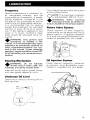
LUBRICATION
Frequency
Routine maintenance is necessary for
all mechanized products, and the
snowmobile is no exception. A weekly
vehicle inspection contributes to the
life span of the snowmobile as well as
retains safe and dependable operation.
It is recommended that the steering
system and suspension be lubricated
monthly or every 40 hours of operation. If the vehicle is operated in wet
snow or in severe conditions these
items should be lubricated more frequently.
A
WARNING: Only perform such
.... procedures as detailed in this
manual. It is recommended that dealer
assistance be periodically obtained on
other components/systems not covered in this manual. Unless otherwise
specified, engine should be turned OFF
for all lubrication and maintenance procedures.
The oil should be level with the bottom
of the oil level orifice.
O
NOTE: The chaincase oil capacity
is approximately 200 mL (7 oz.).
AWARNING: When checking
.... chaincase oil level, be careful not
to burn yourself on the exhaust system.
Rotary Valve System
Check reservoir oil level frequently.
Level should not be below level line of
plastic reservoir. If necessary replenish
to oil level line using Bombardier snowmobile oil available from your dealer.
Steering Mechanism
Oil Injection System
A
WARNING: Do not lubricate
.... throttle and/or brake cable and
housings, and spring coupler bolts.
Check reservoir frequently. Replenish
as required, using Bombardier snowmobile
available from your dealer.
Lubricate the ski legs at grease fittings
until new grease appears at joints.
Chaincase Oil Level
Check the oil level by removing the oil
level cap plug.
Filler
plug
Oil level
19
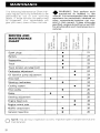
MAINTENANCE
.... WARNING: Only perform such
T procedures as detailed in this
manual. It is recommended that dealer
assistance be periodically obtained on
other components/systems not covered in this manual. Unless otherwise
specified, engine shou Id be tu rned 0 FF
for all lubrication and maintenance procedures.
The following Maintenance Chart indicates
schedules to be
you or your
If these services are . . . r\,.+" .'........ r'rl
as suggested, your snowmobile will
you many years of low-cost use.
SERVICE AND
MAINTENANCE
CHART
•
•
•
•
•
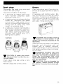
Spark plugs
Battery
Suspension
Track
Track tension and alignment
Carburetor adjustment
Oil injection pump adjustment
•
Drive belt
Steering mechanism
•
Cooling system
Drive pulley
•
Brake
Steering adjustment
•
•
Engine head nuts
Engine mount nuts
•
Muffler attachment
General inspection
O
20
NO.TE: The ten hour
maintenance.
•
IJf../vvl,IV' I
is a very
21
21
22
22
22
•
•
24
24
24
24
•
24
25
25
25
•
•
26
26
26
26
part of proper service and
Spark plugs
Battery
Disconnect the spark plug wires and
remove the spark plugs.
Check electrolyte level. Electrolyte level must be at upper level line on battery
Check the condition of the plugs.
•
A brownish tip reflects ideal conditions. (Correct carburetor, spark
plug heat range; etc.):
• A black insulator
indicates fouling
caused
carburetor idle speed
mixture
high speed mixture
too rich, incorrect fuel mixture
wrong type of spark plug (heat
range), or excessive idling.
If necessary add distilled water. Battery connections must also be free of
corrosion. If cleaning is
remove corrosion
a stiff brush
clean with a solution of baking soda
and water. Rinse and dry well.
• A light grey insulator tip indicates a
lean mixture caused by; carburetor
high speed mixture adjusted too
lean, wrong spark plug heat range,
incorrect fuel mixture
or a
leaking seal or '-"_"JI"'-'~.
Overheated
(light grey)
Fouled
(black)
~
CAUTION: Do not allow cleaning
... solution to enter battery. It will
destroy the chemical properties of the
electrolyte.
After reconnecting
coat battery
terminals and connectors with petroleum jelly to prevent corrosion.
Check that battery is well secured and
that
overflow tube is not blocked or
.& WARNING:
Overflow tube must
be free and open. A kinked or
bent tube will restrict ventilation and
create gas accumulation that could
result in an explosion. Avoid skin contact with electrolyte.
T
~ CAUTION: If spark plug condi-
... tion is not ideal, contact your authorized dealer.
Check spark plug gap using a wire
feeler gauge.
Reinstall plugs and connect wires.
. . . CAUTION: Prior to charging the
... battery, always remove it from
the vehicle to prevent electrolyte spillage.
21
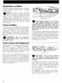
Suspension condition
Visually inspect all suspension components including slider shoes, springs,
wheels, etc ...
.... NOTE: During normal driving,
..... snow will act as a lubricant and
coolant for the slider shoes. Extensive
riding on ice or sanded snow, (not to
mention dirt, asphalt, etc. never recommended) will create excessive heat
build-up and cause premature slider
shoe wear.
Track condition
Lift the rear of the vehicle and support
it off the ground. With the engine off,
rotate the track by hand, and inspect
condition. If worn, cut or track fibers
are exposed or missing or defective inserts or guides are noted, contact your
dealer.
.... WARNING: Do not operate a
..... snowmobile with a cut, torn or
damaged track.
Adjuster blocks
. . , CAUTION: Always turn the left
. . side adjuster blocks in a clockwise direction, the right side blocks in a
counter-clockwise direction. Left and
right adjuster blocks of each adjustment must always be set at the same
elevation.
Lift the rear of vehicle and support with
a mechanical stand. Allow the slide to
extend normally. Check the gap 13 mm
(1 /z") between the slider shoe and the
bottom inside of the track. If the track
tension is too
the track will have
a tendency to thump.
Track Tension and Alignment
The
is adjustable. The front
adjustment is for surface condition,
use the suspension adjustment key.
The rear adjustment is for driver's
weight and should be adjusted using
the 21 mm socket and handle.
13 mm (1/2")
When the front adjuster blocks are at
the lowest elevation more weight is
distributed on the skis. At the highest
position the weight is transferred from
the skis to the track. The rear adjuster
blocks should be adjusted to suit the
driver's preference.
. . , CAUTION: Too much tension
. . will result in power loss and excessive stresses on suspension components.
If necessary to adjust. Loosen the rear
idler wheel retaining screw and then
loosen or tighten adjuster bolts located
on inner side of rear idler wheels. If
correct tension is unattainable. Contact your dealer.
O
NOTE: Track tension and
ment are inter-related. Do not
just one without the other.
22
Start the engine and accelerate slightly
so that track turns slowly. Check that
track is well centered. Equal distance
on both sides between edges of track
guides and slider shoes.
To correct, stop engine loosen the rear
idler wheels retaining screws then loos-en the lock nuts and tighten the adjuster bolt on side where the slider shoe is
the furthest to the track insert guides.
Tighten lock nuts and recheck alignment. Ensure to retighten the idler
wheel retaining screws.
Guides
/ ' Slider'
/
,.
shoes "
~
•
WARNING: Before checking
. . . track alignment, ensure that the
track is free of all particles which could
be thrown out while track is rotating.
Keep hands, tools, feet and clothing
clear of track. Ensure rio-one is standing in close proximity to the vehicle.
23
Carburetor Adjustment
Drive Belt
. . CAUTION: Never operate your
"
snowmobile with the air intake
silencer disconnected. Serious engine
damage wiU occur if this notice is disregarded.
Inspect the belt for cracks, fraying or
abnormal wear (uneven wear, wear on
one
etc.) If abnormal wear is notprobable cause is pulley
ment. Contact your dealer.
Carburetor adjustment shoutd be performed by your dealer.
Check the drive belt width, if less than
3 cm (1 3/16 replace.
OiIIt_tion Pump Adjustment
NOTE: When installing a new
drive belt, a break-in period of 1525 km (10-15 miles) is strongly recommended.
. . CAUTtON: The carburetor must
~ be adjusted before adjusting the
oil injection pump.
Injection pump should be adjusted by
your dealer.
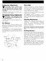
Air Silencer
The air intake silencer elbow must
always be tu rned to the front of the vehicle when
in cold or warm
temperature.
If the vehicle is to be operated in deep
powdered snow it is recommended to
turn the elbow towards the rear of the
vehicle.
Front of
vehicle
11
)
O
Steering Mechanism
Inspect the
mechanism for
tightness of components (steering
arms, tie rods, ball joints, spring
coupler bolts, etc.). If necessary, rear retighten.
Check the condition of the skis and the
ski runners. Replace if worn more than
half.
Cooling System
Place a cloth over the cap and release it
to the first step to check that the cap
the
if not, install a
new 13 Ib cap.
not exceed 13 Ib of
pressure. Using a hydrometer check
that the anti-freeze solution is strong
enough for the temperature in which
the vehicle is operated.
O
NOTE: Should the coolant temperature be above recommended
range 50°-80°C (120°-180°F), hose off
grime from the heat exchanger (underneath the frame above the track).
24
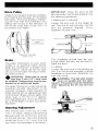
Drive Pulley
Inspect the Duralon
condition
by checking the free-play
the
half pulley. This is achieved by restraining the inner half and checking if the
sliding half moves in the direction of
the arrows more than 3 mm (1/8"). If
so contact your dealer.
IMPORTANT: Close the front of the
skis manually to eliminate all slack from
the steering mechanism.
If adjustment is required:
Loosen the lock nuts of the longer tie
rod. Turn the tie rod manually until the
skis are properly aligned. Firmly
retighten the lock nuts.
Mark reference
on
Maximum
3 mm
halves
11
)
"pe'_"':';1\/
Brake
The brake mechanism on your snowmobile is an essential safety device.
this mechanism in proper working condition. Above all, do not operate your snowmobile without an effective brake system.
.&. WARNING: Brake pad or pucks
.... less than 3 mm (118") thick must
be replaced. Replacement must be performed by an authorized dealer.
The brake mechanism is self-adjusting,
therefore, periodic adjustment is not
required. However, check operation of
brake mechanism by
brake
control level. Brake should
when lever is 13 mm (1
approx.
from handlebar grip. If not, do not tamper with the brake, contact your servicing dealer.
Steering Adjustment
Skis should have a toe out of 3 mm
To check, measure the distance
between each ski at the front and rear
of the leaf
The front distance
should be 3 mm (118") more than the
rear when the handlebar is horizontal.
(1/8").
3 mm (1!8
toe out
The handlebar should also be horizontal when the skis are pointed toward the front.
To
Loosen the lock nuts of the shorter tie
rod. Turn the tie rod manually until the
handlebar is horizontal. Retighten the
lock nuts firmly .
.&. WARNING: The ball joint socket
.... must run parallel with the steering arm. The socket must be restrained
when tightening the tie rod end lock
nuts.
Engine Head Nuts
MuHler Attachment
With the engine cold, check that the
engine head nuts are tight and equally
torqued to 22'N·m (16 ft -lbs).
The engine/exhaust system parts are
vital toward efficient muffler function.
Check all attachments. Replace the
springs and/or tighten if necessary .
. . , CAUTION: Do not operate vehi. . clewith muffler disconnected
otherwise serious engine damage will
occur.
fI
e
G1
I
I
~
Q
9
d
IMPORTANT: The engine head nut
torque should be checked after the first
5 hours of operation.
Engine Mount Nuts
Check the enqine mount nuts for tightness. Retighten if necessary.
26
General Inspection
II
Check the electrical wiring and components, retighten loose connections.
Check for stripped wires or damaged
insulation. Thoroughly inspect the vehicle and tighten
bolts, nuts and
linkage. Inspect skis and ski runners for
wear.
Bulb Replacement
If the headlarnp bulb is burnt, tilt hood,
unplug the connector from the headlamp. Remove the rubber boot and unfasten bulb retainer clips. Detach the
bulb and
If taillight bulb is
burnt, expose the bulb by removing
the red plastic lens. To remove, unscrew the two (2) Phillips head screws.
Verify all lights after replacement
STORAGE
.... WARNING: Only perform such
..... procedures as detailed in this
manual. It is recommended that dealer
assistance be periodically obtained on
other" components/systems not covered in this manual. Unless otherwise
specified, engine should be turned OFF
for all lubrication and maintenance procedures.
When the coolant level is low enough,
remove the engine filler plug.
. . , CAUTION: To prevent rust for... marion in the cooling system, always replenish the system with the
recommended solution (600/0 antifreeze 40 % water).
To refill the cooling system:
Remove
Cooling System
filler plug.
The complete engine cooling system
should be drained and refilled with a
new coolant mixture .
...... WARNING: Never drain or refill
..... the cooling system when the engine is hot.
To drain the
system, siphon
the coolant mixture
the coolant
tank, using a primer pump and a length
of plastic hose and steel tubing inserted as
as possible into the
lower hose of
tank.
.... WARNING: Use a primer pump
.....to siphon the coolant mixture. Do
not siphon with your mouth. The
coolant mixture is poison and can be
fatal if swallowed.
-
Refill tank until coolant overfills at
filler hole .
-
Reinstall filler plug.
Continue to pour the liquid in the
coolant tank until level reaches 2.5 mm
(1 fI) below filler neck.
Reinstall tank cap and start
let
engine run until it reaches its operating
temperature and thermostat opens. Allow it to run a few minutes more
engine and
coolant level, refill as
necessary .
!I....--Primer
pump
.... WARNING: Before removing the
..... cap place a cloth over the coolant
tank and release the cap to the first
step to release the pressure. Loss of
fluid and possibility of severe burns
could occur, if this notice is disregarded.
Track
Ski
Inspect the track for wear, cuts, missing track guides and broken rods.
Make any necessary replacement.
Wash or brush all dirt or rust accumlation from the skis and springs.
Grease the ski legs at the grease fittings. Check the condition of the skis,
ski runners and leaf springs. Replace if
weak or worn more than half.
+
WARNING: Do not operate a
snowmobile with a cut, torn or
damage track.
Lift the rear of vehicle until track is
clear of the ground then support with a
brace or trestle. The snowmobile
should be stored in such a way that the
track does not
in contact with the
cement floor or bare ground.
O
NOTE: The track should be rotated periodicallv. (every 40 days).
Do not release track tension.
. . , CAUTION: To prevent track
.... damage, temperatu re in the storage area must not exceed 38°C (100°F).
Slide Suspension
Remove any dirt or rust. Replace worn
slider shoes.
Grease front idler wheels.
Ski runner
Controls
Lubricate the steering mechanism. Inspect all components for tightness,
(spring coupler bolts, steering arm
locking bolts, tie rods, ball joints, etc.).
Tighten if necessary. Oil moving joints
of the brake mechanism.
...... WARNING: Do not lubricate the
~ throttle and/or brake cable and
housing. Avoid getting oil on the brake
pads.
Coat all electrical connections and
switches with a greaseless metal protector. If unavailable, use petroleum
jelly.
Chaincase
Drain the chaincase and refill to proper
level, using fresh chaincase oil. To
drain, remove the chaincase cover.
Fuel Tank
Remove the cap then using a syphon,
remove the gasoline from tank .
..&. WARNING:
Gasoline is flamma~ ble and explosive under certain
conditions. Always manipulate in a
well ventilated area. Do not smoke or
allow open flames or sparks in the vicinity.
28
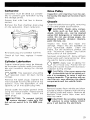
Carburetor
Drive Pulley
Carburetor must be dried out completely to prevent gum formation during
the
period.
Inspection and cleaning must be performed by the dealer at the end of each
season.
Assure that inlet fuel line is disconnected.
Chassis
Remove the float chamber drain plug
on the carburetor. Drain carburetor.
Re-install plug and connect fuel line.
Check all fuel
sary.
if neces-
Cylinder Lubrication
Engine internal parts must be lubrica~
ed to protect cylinder walls from pOSSIble rust formation during the storaoe
period.
O
NOTE: This operation should be
repeated every 40 days during
Remove the spark plugs.
the
rewind starter to bring the piston at top
position. Pour the equivalent of one
of oil into
plug hole.
Slowly crank the engine several times
the manual starter.
above
steps for other cylinder.
the
spark plugs.
. . . CAUTION: To prevent ignition
'Y system damage, make sure that
the cut-out switch is in the OFF position.
Clean the vehicle thoroughly, removing
all dirt and grease accumulation.
. . . CAUTION: Plastic alloy compo... nents such as fuel tank, windshield, controls, etc., can be cleaned
using mild detergents or isopropyl alcohol. Do not use strong soaps, degreasing solvents, abrasive cleaners,
paint thinners, etc.
the hood and repair any
damage. Repair kits are available at
your authorized dealer. Clean the
frame. For the aluminum portion use
only Aluminum cleaner" and follow
instructions on the container.
/I
has been scratched off, Spray allbare
metal parts with metal protector. Wax
the cab for better protection,
O
NOTE: Apply wax on glossy finish of hood only. Protect the vehicle with a cover to prevent dust accumulation during storage.
. . . CAUTION: If for some reason the
... snowmobile has to be stored outside it is necessary to cover it with an
opaque tarpaulin. This caution will prevent the sun rays affecting the plastic
components and the vehicle finish.
Battery
Remove battery from vehicle and dean
outside surface of battery with solution
of baking soda and water, Remove all
deposits from posts then rinse with
clear tap water .
. . , CAUTION: Do not allow cleaning
... solution to enter battery interior
since it will destroy the electrolyte.
29
Check electrolyte level. Refill if necessary with distilled water. Fully charge
battery. (A stored battery should be recharged at least every 40 days).
. . . CAUTION: Prior to charging the
, . battery, always remove it from
the vehicle to prevent electrolyte spillage.
. . . WARNING: Gases given off by a
. . . battery being charged are highly
explosive. Always charge in a well ventilated area. Keep battery away from
cigarettes or open flames. Avoid skin
contact with electrolyte.
Coat battery terminals with petroleum
jelly and store unit in a cool, dry place.
General Inspection
Check the electrical wiri ng and comporetighten loose connections.
for stripped wires or damaged
insu lation.
PREMSEASON
PREPARATION CHART
To be performed by dealer
To be performed by owner
Change spark plugs
Check chaincase oil level
Check drive pulley condition
and clean
Clean fuel filter
Connect fuel lines and check
attaching points
Check
condition, tension
and alignment
Check coolant condition and level
Inspect drive belt and install
Check throttle cable for damage
and free operation
O
Inspect brake condition and operation
Inspect seals for possible cuts or leaks
Check engine timing
PRE-SEASON
PREPARATION
•
Lubricate suspension
Thoroughly inspect the vehicle and
tighten loose bolts, nuts and linkage.
NOTE: Leave the drive belt off
the pulleys for the entire storage
period.
•
Check electrical wiring (broken wire,
damaged insulation)
•
•
•
Inspect condition of starting rope
To simplify the pre-season preparation
we have drawn up a small chart. The
chart indicates servicing points to be
performed by you and your servicing
dealer. If these services are performed
as
your vehicle will give
you many hours of fun and low cost
use.
IMPORTANT: Observe all Warnings
and Cautions mentioned throughout
this manual which are pertinent to the
item being checked. When component
conditions seem less than satisfactory,
with genuine Bombardier parts
or suitable equivalents.
30
Check tightness of all bolts, nuts and
linkage
Refill gas tank
Adjust carburetor and injection pump
Check oil level of rotary valve
reservoir, injector oil reservoir
•
TROUBLE SHOOTING
SYMPTOMS
POSSIBLE CAUSES
WHAT TO DO
Engine turns over but
fails to start or starts
with difficulty
1. No fuel to the engine
Check the tank level and fill up with correct
gas-oil mixture. Check for possible clogging of
fuel line, item 4.
2. Flooded engine
Remove wet
plugs, turn ignition to OFF
and crank
several times. Install clean
dry spark plugs. Start engine following usual
starting procedure. If engine continues to
flood, see your dealer.
3. Spark plug/ignition
Check for fouled or defective spark plug. Disconnect spark plug wire, unscrew plug and remove from cylinder head. Reconnect wire and
ground exposed plug on engine cowl, being
careful to hold away from spark plug hole.
Follow
procedure and check
for spark. no
appear, replace spark
plug. If trouble persists, contact your dealer.
4. Clogged fuel line (water or
dirt)
Remove and clean the fuel filter. Change filter
cartridge if necessary. Check condition and
connections offuel lines. Check the cleanliness
of fuel tank.
Engine will not turn
manually
5.
Incorrect carburetor
adjustment
Contact your dealer.
6.
Incorrect injection
pump adjustment
See your dealer.
7. Engine timing
Engine timing may be defective or out of ad
justment. Contact your dealer.
8. Poor engine compression
Running with a lean fuel mixture may produce
excessive engine wear resulting in poor engine
compression. If this occurs, contact your
dealer at once.
1. Seized engine
In the case of a seized engine contact your
dealer.
31
SYMPTOMS
POSSIBLE CAUSES
WHAT TO DO
Engine lacks acceleration or power
1. Fouled or defective spark
Check item 3 of "Engine turns over but fails
to start or starts with difficulty"
plug
2. Clogged fuel line (water or
dirt)
Engine continually
backfires
Snowmobile cannot
reach full speed
Check fuel line condition. ISee item 4 of "Engine turns over but fails to start or starts
with difficulty"l.
3. Carburetor
Contact your dealer.
4. Ignition
First check item 3 of "Engine turns over but
fails to start or starts with difficulty". If the
ignition system still seems faulty, contact your
dealer.
5. Engine
If unable to locate specific symptoms, contact
your dealer.
1. Spark plug
Check Item 3 of "Engine turns over but fails to
start or starts with difficulty"
2. Overheated
Coolant level too low, refill. Carburetor too
your dealer.
3. Engine timing incorrectly set
Contact your dealer.
1. Drive Belt
Check for damaged or worn drive belt. Replace if necessary.
2. Incorrect track adjustment
Check track tension and alignment. Readjust
specifications. (See Maintenance Section).
to
32
3. Engine
Check item 1 to 5 of "Engine lacks accaler
ation or power."
4. Pulley misaligned
Contact your dealer.
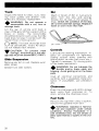
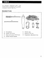
TOOLS
As standard equipment each new
snowmobile is supplied with a basic
tool kit such as screwdriver, ,(\,r,,,,,,,,>hr\C'
emergency starter rope, etc ...
Standard Tools
G
A
CfSS4UD
0
D
()
B
0i
G
A. Screwdriver
E.
Starter rope
B.
F.
Socket 17/21 mm
Socket 10/13 mm
C. Open end wrench 10/13 mm
C
G. Suspension adjustment key
D. Socket wrench handle
33
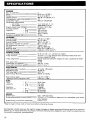
SPECIFICATIONS
ENGINE
No. of cylinders
Bore
Stroke
Displacement
Compression ratio (corrected)
Carburetor type
Carburetor adjustment
- air screw
idle speed
Engine head nuts
Cooling system
capacity
2
69.5 mm (2.736")
61 mm (2.401")
462.8 cm3 (28.24 in. 3 )
7:1
Mikuni VM 34-227
Thermostat
Radiator pressure cap
1 112 turn out ± 1/8
1800-2000 R.P.M.
22 N.m (16 tt-lbs)
4.54 liters
160 ounces
154 ounces
43°C (110°F)
13 Ibs
CHASSIS
Overalliength
Overall width
Overall height
Ski stance (center to
Ski alignment (toe out)
Weight
Bearing area
Ground pressure
276.8 cm (109")
99 cm (39")
106.7 em (42")
85.1 cm (33 1/2")
3 mm (1/8")
229 kg (505 Ibs)
8710 cm2 (1350 in. 2 )
2.58 kPa (.374 Ibs/in2 )
POWER TRAIN
Track dimensions
Track tension
Std. gear ratio
Chaincase oil capacity
Drive belt (minimum width)
41.9 cm (16 1/2") x 314.9 cm (124")
13 mm (112") gap should exist between slide shoe and
bottom inside of track
Equal distance between edges of track guides and slider
shoes
17/34
200 mL (7 ozl
3 em (1 3/16")
ELECTRICAL
Lighting system (output)
Headlamp bulb
Tail/stop light
Spark plug (Bosch)
12 volts, 140 watts
45/45 W
5/21 W
W275 T2 (W3C)
Track alignment
Spark plug (gap)
0.4 mm (.016")
*Ignition timing (e-n-g""":i-ne-c-o:-'Id:":"")--- 2.52 mm 1.099")
FUEL
Tank
capacity
Gasoline
Injection oil
S 1*
Imp.
U.S.
S 1*
Imp.
- U.S.
29.5 liters
6.5 gals
7.8 gals
Regular
2.36 liters
80 ounces
76 ounces
BRAKE
Brake type
Disc, self-adjusting
Brake adjustment (control lever) _ _ 13 mm (112") minimum distance from handlebar grip when
fully applied
Brake lining (minimum thickness) __ 3 mm (1/8")
*Warm engine must cool of one hour before checking timing
Bombardier Limitee reserves the right to make changes in design and specifications and/or to make additions to, or improvements in its product without imposing any obligation upon itself to install them on
its product previously manufactured.
34
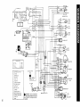
OFF
ON
I
MU/'''.
~ START
SWITCH
KILL
SWITCH
DIMMER
SWITCH
.~D/WH
~
I
OIL LEVEL LIGHT
GN
RD
OIL LEVEL SWITCH
RD/WH
TEMPERATURE
AI
GAUGE
FUSE
HEADLAMP (4S/45WI
TAILLAMP
LIGHT (SWl
BATTERY
STARTER
A.l
SOLENOID SWITCH
REGULATOR RECTIFIER
TEMPERATURE SENSOR
W
01
LIGHT 12WI
DIODE
BRAKE LIGHT SWITCH
81* METRIC INFORMATION GUIDE
BASE UNITS
SYMBOL
DESCRIPTION
UNIT
mass
liquid
temperature
pressure
torque
meter
kilogram
liter
celsius
kilopascal
Newton meter
kilometer per hour
speed
m
kg
L
°C
kPa
N·m
km/h
PREFIXES
PREFIX
kilo
centi
rnilli
SYMBOL
MEANING
VALUE
k
c
m
one thousand
one hundredth of a
one thousandth of a
1,000
0.01
0.001
*THE INTERNATIONAL SYSTEM OF UNITS (SYSTEME INTERNATIONAL)
ABREVIATES -sr: IN ALL LANGUAGES.
36
CHANGE OF ADDRESS AND OWNERSHIP
Any change in address or ownership should be brought to the attention of the
manufacturer by completing and sending out the card supplied below.
~
:
: CHANGE OF ADDRESS
.----------------------------: VEHICLE tDENTIFICAnON NUMBER
: OLD ADDRESS:
NAME
NO
: NEW ADDRESS:
··
·
•
NAME
NO
•
CITY
:
ZIP /
~
: CHANGE OF OWNERSHIP
: VEHICLE IDENTIFICATION NUMBER
·: The ownership of this vehicle is transferred
·: FROM:
·
··
·
·
·
_
NAME
NO
/ POSTAL CODE
TO:
NAME
NO
ZIP /
37
.................................................................................
····
·
···
·
···
BOMBARDIER LIMITEE
ATT.: WARRANTY DEPARTMENT
····
···
VALCOURT,OUEBEC
CANADA, JOE 2LO
·
··
··
··
·
·
.................................................................................
···
·
·
·
·
BOMBARDIER LIMITEE
·
ATT.: WARRANTY DEPARTMENT
·
VALCOURT,OUEBEC
CANADA, JOE 2LO
·
···
·
···
·
··
·
··
38