1
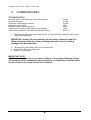
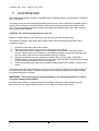
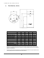
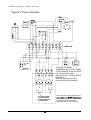
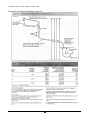
smart line E
SLE 130 – 300
IMPORTANT!
DO NOT UNDER ANY CIRCUMSTANCES SWITCH ON THE
IMMERSION HEATER BEFORE THE PRIMARY TANK IS FILLED.
INDEX
INTRODUCTION
1
Intended users of these instructions
Warnings
1
1
1. Operation
2
2. Construction
3
3. Installation
Domestic
4
Wiring the thermostats
5
Primary
5
Immersion Heater
6
4. Commissioning
7
5. Maintenance
8
6. Technical Data
9
7. Performance
10
8. System Schematics
Typical un-vented
Typical open vented
Typical ‘S-Plan’ electrical
Typical ‘Y-Plan’ electrical
9. Discharge Pipe
Extract of ‘Building reg. G3’
11
11
12
13
14
15
10. Parts List
16
11. Technical Assistance & Order Info.
16
T E C H N I C A L
A N D
I N S T A L L A T I O N
INTRODUCTION
Intended users of these instructions:
-
The specifying engineer.
The installation engineer.
The owner or user.
The service engineer.
Warnings.
THE INSTALLER MUST READ AND UNDERSTAND THIS MANUAL BEFORE FITTING
THIS APPLIANCE.
IMPORTANT: Do not under any circumstances switch on the immersion heater
before the primary tank is filled.
Serious damage may result to the heater in addition to danger of personal injury
and damage to property if the heater is switched on when dry.
IMPORTANT: Always isolate electrical supplies and if necessary the water supply
before working on the unit.
IMPORTANT: Always fill and pressurise the secondary (domestic) tank first, filling
and pressurising the primary (heating) tank may result in crushing damage to the
domestic tank.
IMPORTANT: ACV recommends the use of a corrosion inhibitor in the primary
(heating) system. The warranty will be invalidated if upon inspection it is found
that a tank has failed due to corrosion caused by the lack of an inhibitor.
These instructions form an integral part of the equipment to which they refer and the user
must be provided with a copy.
The product must be installed and serviced by qualified engineers, in compliance with
current standards.
ACV cannot accept liability for any damage resulting from incorrect installation or from
the use of components or fittings not specified by ACV.
Any failure to follow the instructions regarding tests and test procedures may result in
personal injury.
ACV reserves the right to change the technical specifications and components of its
products without prior notice.
1
T E C H N I C A L
A N D
I N S T A L L A T I O N
1. OPERATION
A = Stainless steel internal tank
B = STW 22 carbon steel exterior tank
C = High density polyurethane foam insulation
D = Heating fluid entry point
E = Heating fluid outlet point
F = Sanitary hot water outlet
G = T & P relief valve connection
H = Cold water inlet
I = Control thermostat
K = Control thermostat pocket
L = Primary air vent
M = Co-polymer polypropylene top cover
N = Co-polymer polypropylene jacket
Principle:
ACV Tanks (tank in tank) comprise of two concentric water cylinders. Tank (A) is manufactured in
solid stainless steel and contains the domestic water for use at the sanitary hot water outlets. The
exterior tank (B) is manufactured from STW 22 carbon steel, this tank holds the primary heating
fluid which is circulated from the boiler, as the primary fluid passes between the two tanks the
heat is transferred to the domestic water.
Operation:
When the thermostat (I) calls for heat the primary pump is activated (or motorised valve is
opened) and primary fluid is circulated in the outer tank and transfers its heat to the domestic
water. Once the thermostat set temperature is achieved it will open and deactivate the primary
pump (or close the motorised valve). Initial heating from cold will take between 10 and 20 minutes
(depending on tank size and boiler output) – when operating temperature is achieved the
recovery becomes faster.
Operational Cycle:
2
T E C H N I C A L
2.
A N D
I N S T A L L A T I O N
CONSTRUCTION
Internal tank:
This tank is the heart of the assembly; it has to withstand the corrosive nature of mains water and the
temperature variations of stored water whilst working at high pressures. It is manufactured from solid
stainless steel and welded in an inert Argon atmosphere (Argon Arc). Before being assembled the tank
material is subjected to a rigorous cleaning and passivation process to increase its resistance to
corrosion. The inner tank is also corrugated which allows it to freely expand and contract with
temperature and pressure variations, shrugging off any lime scale deposits. Due to this, the tank does
not require an inspection cover to facilitate the removal of lime.
Insulation:
High density injected polyurethane foam – 50mm thick. Containing no CFC’s.
Jacket:
The tank is covered in a co-polymer polypropylene jacket, this is a plastic material that offers a high
resistance to impact and is also aesthetically pleasing.
Controls:
The tanks come complete with a control and high limit thermostat built into the top cover of the jacket.
Thermostat control:
The control is graduated from 1 to 5, 1 is minimum = 60°C and 5 is maximum = 90°C.
In the case of a prolonged absence precautions must be taken to ensure there is no risk of freezing.
The tank is delivered with the thermostat pre-set to a minimum of 65°C to eliminate the risk of legionella
bacteria forming and complies with the recommendations of the World Health Organisation. The
thermostat control dial can be removed to allow lower temperature settings, see sketch and description
below.
Modifying the IMIT thermostat:
1. Remove the control dial.
2. Take out the metal spring stop.
3. Replace the control dial.
3
T E C H N I C A L
3.
A N D
I N S T A L L A T I O N
INSTALLATION (130 to 300 Smart Paks)
Domestic:
Parts List.
1. Pressure control valve 3.5bar.
2. Expansion vessel 3.5bar.
3. Check/Expansion valve assembly 6bar.
4. Thermostatic mixing valve.
5. Temperature & pressure relief valve 7bar.
6. Tundish.
1 in No. 22mm equal tee.
1 in No. 22mm elbow.
2 in No. 22mm x 3/4" FI BSP Adaptors.
5 lengths 22mm Copper tube (A to C on drawing).
Note: Secondary return pipework and fittings are not included in
the kit.
Guidance for Installation.
1. Connect 22mm x 3/4" FI BSP adaptors to cold water inlet (blue) and hot
water outlet (red) connections on tank.
installed correctly, cold/hot inlet ports are marked on body, i.e. hot to H cold
to C outlet to MIX.
Note:- discharge pipework to tundish is not supplied.
3. Orientate mixing valve hot water outlet to desired position and tighten.
4. Connect Check/Expansion valve to cold water inlet pipe (A) and orientate
Expansion vessel connection to suit installation.
5. Connect Pressure Reducing Valve to Check/Expansion valve (a light
smear of jointing compound to PTFE ring will ease assembly) and orientate
to ensure balanced cold water take-off faces either front or rear (blank
supplied if take-off is not to be used).
6. Remove 3/4" black plastic plug from Check/Expansion valve and fit
Expansion Vessel (seal with PTFE tape).
7. Connect Temperature and Pressure relief valve to 1/2" connection and
orientate into position. Do not run drain discharge pipework across top of
tank.
8. Connect both Temperature and Pressure relief valve/Expansion valve
discharge pipework across top of tank.
9. Install Tundish outlet pipework as per Building regulation G3 (for further
guidance refer to controls installation and maintenance instructions).
Flush pipework and commission.
4
T E C H N I C A L
A N D
I N S T A L L A T I O N
Wiring the thermostat:
To comply with ‘The Building Regulation 1991 G3.6’ the manual reset high limit thermostat must be
wired to a self-closing motorised valve or some other suitable device to shut off the primary flow to the
cylinder.
The thermostatic controller should be used to regulate the temperature of the tank by controlling the
heating pump or zone valve supplying the unit (note that a spring return valve must be connected to the
high limit stat for normal operation, i.e. the valve will be energised to open by the thermostat and then
spring closed when the circuit is broken). The switch wire from the pump or valve can be wired to the
tank controls via the 6 pin plug. See diagram below.
Thermostat wiring schematic.
High Limit Stat
Thermostat
Factory Wired
Installer Wired
Please note N is a switched LIVE not NEUTRAL.
(Typical ‘S & Y-plan’ wiring schematics are on pages 12 &13).
ACV recommend that the cylinder is electrically cross bonded to earth.
Primary system connections:
The primary flow and return connections to the tank should be made using the appropriate sized fittings
with a male BSP component that will allow the disconnection and removal of the unit. A self-closing
motorised valve or some other suitable device must be fitted to shut off the primary flow to the cylinder.
Care must be taken to ensure that the connections are watertight to avoid any leakage that may go
undetected and cause external corrosion damage to the tank.
Distribution Pressure
The mains water supply must be fed to the unit via the supplied mains kit, this will maintain a
maximum distribution pressure of 3.5 Bar.
Purging
After filling and before using it will be necessary to purge air from both the primary (heating) and
secondary (domestic) tanks. The domestic can be purged by opening a hot outlet at the highest
point (or by venting the temperature and pressure relief valve), the primary (heating) tank can be
vented using the air vent located on the top of the tank (ensure vent is tightened after use).
5
T E C H N I C A L
A N D
I N S T A L L A T I O N
Immersion Heater
The SmartLineE range of tanks have the facility for fitting a 3kW immersion heater for back-up
emergency use when the primary heating fails not as a permanent form of summer time
heating, this heater must be wired to its own 13 Amp fused spur and as described in the
installation instructions for Thermtec immersion heaters.
Installation Instructions for Thermtec Immersion Heaters Series AF, BF, CF, DF, AD, BD, CD, DD.
1. Ensure mains voltage corresponds to the voltage rating of the heater as shown on the
rating label on the terminal cover.
2. Install the heater into the water tank, using the gasket or ‘O’ ring supplied (the use of
sealing compounds is not recommended). Use a shaped spanner to tighten (stillsons
should not be used).
3. It is essential that water fully covers the heating element to a depth of at least 100mm.
Under no circumstances must the heater be permitted to run dry – serious damage may
result to the heater in addition to danger of personal injury and damage to property.
4. Check for possible leakage before wiring.
5. Wire the heater in accordance with the diagram below. The heater should be wired
through a double pole isolating switch or controller, having contact separation of at least
3mm using 1.5sqmm flexible cable, 85°C rubber insulated HOFR sheathed, complying
with BS6141 Table 8. It must be fully earthed. Ensure all terminals are securely made,
however do not use excessive force when tightening.
6. BEAB approval will only apply to this heater if the following thermostats are used:
Series AD, BD, CD, DD control thermostat – Diamond H WT Series or Sunvik VKL
Series. Re-settable master thermostat – Sunvik Series VKL and Thermtec SK. Series
AF, BF, CF, DF. Thermowatt type RTS-3 thermostat.
7. In the event of the manually resettable cut out operating, isolate the heater from the
mains, investigate and identify the cause of cut out, rectify before resetting and then reenergise the heater. Replace the terminal cover securely before re-energizing.
8. All heaters conform to EEC directive 76/889 for radio interference and comply with BS
800:1977.
BEAB
APPROVED
Heater Series
AD, BD, CD, DD
Heater Series
AF, BF, CF, DF
WARNING!
UNDER NO CIRCUMSTANCES CAN THE IMMERSION HEATER BE
SWITCHED ON BEFORE THE PRIMARY TANK IS FILLED.
SERIOUS DAMAGE MAY RESULT TO THE HEATER IN ADDITION TO
DANGER OF PERSONAL INJURY AND DAMAGE TO PROPERTY IF
HEATER IS SWITCHED ON WHEN DRY.
6
T E C H N I C A L
4.
A N D
I N S T A L L A T I O N
COMMISSIONING
Characteristics:
Maximum water supply pressure to the reducing valve
Operating pressure
Expansion vessel charge pressure
Expansion valve setting
Maximum primary working pressure
Temperature & pressure relief valve pressure setting
Temperature & pressure relief valve temperature setting
16 Bar
3.5 Bar
3.5 Bar
6 Bar
3 Bar
7 Bar
92-95 °C
1. Flush the tank with fresh mains water then fill, vent and pressurise domestic water circuit
as previously described.
IMPORTANT: Always fill and pressurise the secondary (domestic) tank first,
filling and pressurising the primary (heating) tank may result in crushing
damage to the domestic tank.
2. Fill the primary circuit taking care not to exceed 2 Bar.
3. Purge the air from the primary tank.
4. Switch on and operate.
IMPORTANT NOTE:
ACV recommends the use of a corrosion inhibitor in the primary (heating) system.
The warranty will be invalidated if upon inspection it is found that a tank has failed
due to corrosion caused by the lack of an inhibitor.
7
T E C H N I C A L
5.
A N D
I N S T A L L A T I O N
MAINTENANCE
ACV recommend that the cylinder is maintained by a competent person, this should be carried out
every 12 months.
The safety valves must be manually operated at least once a year to check their operation and reseating. Allow cylinder to cool before slowly twisting open the temperature and pressure relief
valve. The water should flow freely through the tundish and discharge pipe work, check that the
valve reseats when released.
CAUTION: The water discharged may be very hot.
Repeat the steps above for the expansion relief valve on the cold inlet pipe work.
The pressure reducing valve (PRV) has a strainer that can be removed for inspection and if
necessary cleaning.
i.
ii.
iii.
iv.
v.
vi.
Isolate the cold water inlet to the cylinder.
Open the lowest hot tap to remove the pressure from the system.
The black plastic PRV cartridge can be unscrewed from the brass valve body, loosen
using a suitable spanner (not stilsons or pump pliers) unscrew and pull the cartridge from
the valve body, the strainer will be withdrawn with the cartridge.
Remove the strainer from the cartridge and clean under running water if necessary.
Replace strainer and push cartridge into valve body, take care when screwing the cartridge
in not to damage the threads. Do not over tighten.
Close hot tap and slowly open the cold water isolating valve to the cylinder, check for any
leaks.
The primary tank should be checked for a build up of air, this can be purged using the primary air
vent on the top of the cylinder. Check the primary system pressure gauge on the boiler or filling
loop and recharge as necessary.
IMPORTANT: If the primary system is being topped up on a regular basis there is a risk of
corrosion damage to the cylinder.
The tank must be fitted by means of screwed couplings or flanges to allow dismantling and
removal of the unit. These should be fitted in such a way as to allow easy access.
8
T E C H N I C A L
6.
A N D
I N S T A L L A T I O N
TECHNICAL DATA
Type
Code
Unvented Kit
Total Capacity (ltrs)
Heating Fluid Capacity (ltrs)
Domestic Water Capacity (ltrs)
Primary press. drop (mbar)
Immersion heater connection
Primary fluid connections
Domestic water connections
Dimension: A (mm)
B (mm)
C (mm)*
Weight empty (kg)
Weight full (kg)
Heating surface (m²)
Primary fluid flow (ltrs/hr)
Absorbed Power (kW)**
Start-up time from 10 to 85°C(min)
SLE 130
06604801
130
55
75
17
1½” BSP
1” BSP
¾” BSP
525
960
1460
55
185
1.03
2100
23
22
SLE 160
SLE 210
06604901
06605001
Smart Pak1 (12ltr)
161
203
62
77
99
126
22
37
1½” BSP
1½” BSP
1” BSP
1” BSP
¾” BSP
¾” BSP
725
997
1160
1435
1660
1935
65
75
226
278
1.26
1.54
2600
3500
31
39
22
20
SLE 240
06605101
242
78
164
45
1½” BSP
1” BSP
¾” BSP
1244
1680
2180
87
329
1.94
4200
53
20
SLE 300
06605201
SP2 (18ltr)
293
93
200
51
1½” BSP
1” BSP
¾” BSP
1550
1988
2488
102
395
2.29
5300
66
20
*
Dimension C is the approximate total height with mains kit fitted including expansion, please be aware
that this kit is adaptable should there be a restriction on the height. Please contact ACV UK Ltd technical
support for any assistance.
**
The boiler outputs shown are the minimum to provide the domestic performance figures detailed. Should
a lower capacity boiler be used the performance will be reduced.
9
T E C H N I C A L
7.
A N D
I N S T A L L A T I O N
PERFORMANCE
Performances
Type
1st hour output
(ltrs/60min)
Peak output
(l/10min)
40°C
236
321
406
547
700
SLE 130
SLE 160
SLE 210
SLE 240
SLE 300
45°C
202
275
348
469
600
60°C
117
161
209
272
337
Operating conditions:
*
40°C
784
1063
1349
1820
2319
45°C
672
911
1156
1560
1988
60°C
384
549
689
913
1165
primary fluid
cold inlet
Continuous output
(ltrs/hr)
40°C
658
890
1132
1527
1943
45°C
564
763
970
1309
1665
60°C
320
465
576
769
994
Boiler
Output
(kW)*
Primary
flow rate
(ltrs/hr)
Heat up time
10°C–85°C
(min)
23
31
39
53
66
2100
2600
3500
4200
5300
22
22
20
20
20
85°C
10°C
The boiler outputs shown are the minimum to provide the domestic performance figures
detailed. Should a lower capacity boiler be used the performance will be reduced.
10
T E C H N I C A L
8.
A N D
I N S T A L L A T I O N
SYSTEM SCHEMATICS
Typical un-vented application.
Typical open vented application.
11
T E C H N I C A L
A N D
I N S T A L L A T I O N
Typical ‘S-Plan’ schematic.
CONTROL TERMINAL
NUMBERING MAY DIFFER FROM
THOSE SHOWN. ALWAYS REFER
TO THE INSTRUCTIONS
SUPPLIED WITH YOUR CONTROL
PACKAGE.
ACV 6 PIN SOCKET
FACTORY WIRED
N IS SWITCHED LIVE
NOT NEUTRAL
12
THIS DIAGRAM IS FOR GUIDANCE ONLY.
ACV ACCEPT NO LIABILITY FOR DAMAGE
TO EQUIPMENT ARISING FROM ERRORS
OR OMISSIONS INADVERTENTLY
CONTAINED WITHIN THIS DIAGRAM.
T E C H N I C A L
A N D
I N S T A L L A T I O N
Typical ‘Y-Plan’ schematic.
CONTROL TERMINAL
NUMBERING MAY DIFFER FROM
THOSE SHOWN. ALWAYS REFER
TO THE INSTRUCTIONS
SUPPLIED WITH YOUR CONTROL
PACKAGE.
SWITCH WIRES ON 2 PORT
VALVE ARE NOT REQUIRED.
ACV 6 PIN SOCKET
FACTORY WIRED
N IS SWITCHED LIVE
NOT NEUTRAL
13
THIS DIAGRAM IS FOR GUIDANCE ONLY.
TO EQUIPMENT ARISING FROM ERRORS
OR OMISSIONS INADVERTENTLY
CONTAINED WITHIN THIS DIAGRAM.
T E C H N I C A L
9.
A N D
I N S T A L L A T I O N
DISCHARGE PIPE
The discharge pipe (D2) from the tundish should terminate in a safe place where there is no
risk to persons in the vicinity of the discharge, be of metal and:
a. be at least one size larger than the nominal outlet size of the safety device unless its
total equivalent hydraulic resistance exceeds that of a straight pipe 9m long i.e.
discharge pipes between 9 and 18m equivalent resistance length should be at least
two sizes larger than the nominal outlet size of the safety device, between 18 and 27m
at least 3 sizes larger, and so on. Bends must be taken into account in calculating the
flow of resistance. Refer to Diagram 1, Table 1 and the worked example overleaf.
b. have a vertical section of pipe at least 300mm long, below the tundish before any
elbows or bends in the pipework.
c. be installed with a continuous fall.
d. have discharges visible at both the tundish and the final point of discharge but where
this is not possible or is practically difficult there should be clear visibility at one or
other of these locations. Examples of acceptable discharge arrangements are:
i.
ideally below a fixed grating and above the water seal in a trapped gully.
ii.
downward discharges at low level; i.e. up to 100mm above external surfaces
such as car parks, hard standings, grassed areas etc. are acceptable providing
that where children may play or otherwise come into contact with discharges a
wire cage or similar guard is positioned to prevent contact, whilst maintaining
visibility.
iii.
discharges at high level; e.g. into a metal hopper and metal down pipe with the
end of the discharge pipe clearly visible (tundish visible or not) or onto a roof
capable of withstanding high temperature discharges of water and 3m away
from plastic guttering system that would collect such discharges (tundish
visible).
iv.
where a single pipe serves a number of discharges, such as in blocks of flats,
the number served should be limited to not more than 6 systems so that any
installation discharging can be traced reasonably easily. The single common
discharge pipe should be at least one pipe size larger than the largest
individual discharge pipe (D2) to be connected. If un-vented hot water storage
systems are installed where discharges from safety devices may not be
apparent i.e. in dwellings occupied by blind, infirm or disabled people,
consideration should be given to the installation of an electronically operated
device to warn when discharge takes place.
Note: The discharge will consist of scalding water and steam. Asphalt, roofing felt and nonmetallic rainwater goods may be damaged by such discharges.
14
T E C H N I C A L
A N D
I N S T A L L A T I O N
Extract from ‘The Building Regulations 1991 G3’
15
T E C H N I C A L
A N D
I N S T A L L A T I O N
10. PARTS LIST
Description
300mm Immersion Heater 11/2" BSP 3KW
Thermostat pocket
Manual air vent
Control thermostat
Manual reset high limit thermostat 90°C
Sparge pipe Ø19.5mm, length 700mm Smart 130
Sparge pipe Ø19.5mm, length 870mm Smart 160
Sparge pipe Ø19.5mm, length 1070mm Smart 210
Sparge pipe Ø19.5mm, length 1340mm Smart 240
Sparge pipe Ø19.5mm, length 1590mm Smart 300
11. TECHNICAL ASSISTANCE &
ORDER INFORMATION
Telephone: 01383 820 100
Fax: 01383 820 180
e-mail: [email protected]
web address: www.acv-uk.com
ACV UK Ltd.
St. Davids Business Park
Dalgety Bay
Fife
KY11 9PF
Scotland
Manufactured at:
ACV International
Kerkplein 39
B – 1601 Ruisbroek
Belgium
Telephone: 0032 237 81235
e-mail: [email protected]
web address: www.acv.com
16
Code
OI300
438027
445006
54442045
54764020
497b0003
49410116
49410170
49410043
49410169