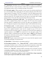
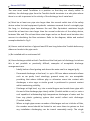
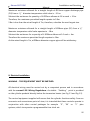
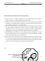
1
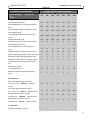
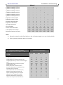
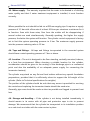
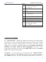
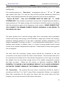
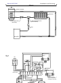
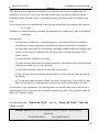
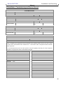
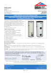
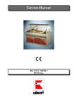
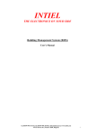
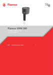
Schuco SS-TC/SC Cylinders Installation, User and Service Manual Domestic Hot Water Cylinder Storage Capacities 90, 125, 150, 170, 200, 250 & 300, Litres Twin Coil, Storage Capacities 150, 200, 250 300, Litres Installation and Servicing Schuco SS-TC/SC Manual Important -This Manual should be left with the Cylinder after Installation Schueco UK Ltd: Solar Division, Whitehall Avenue, Kingston, Milton Keynes, MK10 0AL Tel (01908) 282111 Fax (01908) 289123 www.schueco.co.uk 4140-42-C Schuco SS-TC/SC, Direct, Indirect & Twin Coil Cylinder Range Installation, User and Service Manual Index Section Page 1 Introduction 2 2 Technical specifications 3 3 Check list 3 4 General requirements 4 5 Primary circuit installation 6 6 Secondary circuit installation 12 7 Discharge arrangement 14 8 Electrical Installation 17 9 Filling and commissioning 19 2 Installation and Servicing Schuco SS-TC/SC Manual 10 Servicing and maintenance 20 11 Fault finding 21 12 User instructions 22 13 Warranty 22 14 Installation, commissioning and service record 23 1. Introduction The “Schuco SS-TC/SC” is a high quality stainless steel hot water cylinder suitable for use on “unvented” or “open vented” hot water systems. The indirect heat exchange surfaces are designed to provide a rapid heat up. The indirect unit incorporates a 3kW electric immersion heater as a “backup” or for summer use. When the unit is supplied for unvented applications, it comes complete with all the necessary safety equipment to comply with legislation governing the installation of such systems. The temperature and pressure relief valve is factory fitted. The “Schuco SS-TC/SC” twin coil range has a second coil that can be used for fuel sources such as Solar, Biomass (wood burning stoves), range cookers and heat pumps. All the installation, user and service instructions given for the “Schuco SS-TC/SC” range also apply to the “Schuco SS-TC/SC” range unless otherwise stated. 3 Installation and Servicing Schuco SS-TC/SC Manual 2. Technical specifications Model Number Schuco SS- Single Coil & Direct Cylinders 90 125 150 170 200 250 300 Storage capacity (litres) 90 125 150 170 200 250 300 Overall diameter (mm) 533 533 533 533 533 533 533 595 595 595 595 595 595 595 755 980 1105 1255 1455 1755 2065 1083 1308 1433 1583 1816 2167 2477 120 159 188 212 246 299 353 22 22 22 22 22 22 22 - - - - - - Yes 22 22 22 22 22 22 28 Maximum water supply pressure (bar) 12 12 12 12 12 12 12 System operating pressure (pre-set) (bar) 3 3 3 3 3 3 3 Expansion vessel charge pressure (bar) 3 3 3 3 3 3 3 Expansion relief valve set pressure (bar) 6 6 6 6 6 6 6 Lift pressure (bar) 7 7 7 7 7 7 7 Lift temperature (ºC) 90 90 90 90 90 90 90 3 3 3 3 3 3 3 26 36 37 36 33 35 40 52 72 86 98 108 144 202 18 25 26 25 24 25 29 27 37 45 51 63 75 136 1 - - - - - - TC/SC Overall diameter incl. immersion heater mm Overall height with exp. vessel on cold feed supply (mm)1 Overall height with exp vessel on top (mm)1 Weight when full (kg) Primary flow/return connections (mm) Secondary return (mm) Cold feed/hot draw off connections (mm) Temperature and pressure relief valve set: Maximum primary working pressure (bar) Performance: Hot water generation time from 15 to 65 ºC for ‘Indirect’ cylinder (min) Hot water generation time from 15 to 65 ºC for ‘Direct’ cylinder (min) Regeneration time for 70% of Contents for ‘Indirect’ cylinder (min) Regeneration time for 70% of Contents for ‘Direct’ cylinder (min) 3. Check list Cylinder assembly 90 litre 4 Installation and Servicing Schuco SS-TC/SC Manual Cylinder assembly 125 litre - 1 - - - - - Cylinder assembly 150 litre - - 1 - - - - Cylinder assembly 170 litre - - - 1 - - - Cylinder assembly 200 litre - - - - 1 - - Cylinder assembly 250 litre - - - - - 1 - Cylinder assembly 300 litre - - - - - - 1 Expansion vessel 12 litre 1 1 1 1 1 - - Expansion vessel 19 litre - - - - - 1 1 Pressure reducing valve 1 1 1 1 1 1 1 Expansion relief valve 1 1 1 1 1 1 1 T/P valve, pre fitted 1 1 1 1 1 1 1 15/22 Tundish 1 1 1 1 1 1 1 1(0) 1(0) 1(0) 1(0) 1(0) 1(0) 1(0) Control/limit thermostat2 1(0) 1(0) 1(0) 1(0) 1(0) 1(0) 1(0) Immersion heater not fitted2 1(1) 1(2) 1(2) 1(2) 1(2) 1(2) 2(2) 22mm motorised valve2 Note: 1. Expansion vessels can be fitted either on the cold water supply or on top of the cylinder. 2. Direct cylinder quantities shown in brackets. 2B. Technical specifications Model Number Schuco SS- Twin Coil Cylinders 150 TC 200 TC 250 TC 300 TC Storage capacity (litres) 150 200 250 300 Overall diameter (mm) 533 533 533 533 Overall diameter incl. immersion heater mm 595 595 595 595 1105 1455 1755 2065 Overall height with exp vessel on top (mm)1 1433 1816 2167 2477 Weight when full (kg) 188 249 299 356 Primary flow/return connections (mm) 22 22 22 22 Dual fuel coil flow/return connections (mm) 22 22 22 22 Secondary return connection Yes Yes Yes Yes Cold feed/hot draw off connections (mm) 22 22 22 28 Maximum water supply pressure (bar) 12 12 12 12 System operating pressure (pre-set) (bar) 3 3 3 3 Expansion vessel charge pressure (bar) 3 3 3 3 Expansion relief valve set pressure (bar) 6 6 6 6 Temperature and pressure relief valve set: 7 7 7 7 TC/SC Overall height with exp. vessel on cold feed supply (mm)1 5 Installation and Servicing Schuco SS-TC/SC Manual Lift pressure (bar) Lift temperature (ºC) 90 90 90 90 Maximum primary working pressure (bar) 3 3 3 3 Maximum lower primary working pressure (bar) 3 3 3 3 37 - 35 - 86 - 144 - 26 - 25 - 45 - 75 - - Performance: Hot water generation time from 15 to 65 ºC for ‘Indirect’ cylinder (min) Hot water generation time from 15 to 65 ºC for ‘Direct’ cylinder (min) Regeneration time for 70% of Contents for ‘Indirect’ cylinder (min) Regeneration time for 70% of Contents for ‘Direct’ cylinder (min) 3. Check list Cylinder assembly 150 ltr 1 Cylinder assembly 200 ltr - 1 - Cylinder assembly 250 ltr - - 1 - Cylinder assembly 300 ltr - - - 1 Expansion vessel 12 ltr – 150 Ltr & 200 Ltr 1 1 - - Expansion vessel 19 ltr – 250 Ltr & 300 Ltr - - 1 1 Monoblock 1 1 1 1 T/P valve, pre fitted 1 1 1 1 15/22 Tundish 1 1 1 1 22mm motorised valve2 1 1 1 1 1 1 1 1 1 1 1 1 Control/limit thermostat2 Immersion heater Note: 1. Expansion vessels can be fitted either on the cold water supply or on top of the cylinder. 4. General requirements 4.1. The “Schuco SS-TC/SC” domestic hot water cylinder MUST be installed by a competent person in accordance with section G3 of the current Building Regulations. 4.2. Important - It is important that the installer reads and understands these instructions, unpacks and familiarises themselves with the equipment before commencing the installation. Failure to observe these installation instructions could invalidate the warranty. 6 Installation and Servicing Schuco SS-TC/SC Manual 4.3. Water supply - The warranty requires that the water to be heated is of drinking water quality and that if water treatment equipment is installed, it must function correctly. Where possible the unit should be fed via a Ø22mm supply pipe. It requires a supply pressure of 1.5 bar with a flow rate of at least 20 litres per minute as a minimum for it to function. Even with these rates, flow from the outlets will be disappointing if several outlets are used simultaneously. Generally speaking, the higher the supply pressure, the better the system will function. The cylinder control equipment is factory set to limit the system operating pressure to 3 bar. The maximum supply pressure into the pressure-reducing valve is 12 bar. 4.4. Taps and fittings - All taps and fittings incorporated in the unvented system should have a rated operating pressure of 7 bar or above. 4.5. Location – The unit is designed to be floor standing, vertically mounted, indoors, in a frost-free environment. When choosing a suitable location for the cylinder, consideration should be given to the routing of the discharge pipe to a convenient point and also the availability of an adequate power supply for connecting the immersion heater(s). The cylinder may stand on any flat and level surface without any special foundation preparations, provided that it is sufficiently robust to support the full weight of the cylinder. (Refer to Technical specifications for weights). The position of the cylinder should be such that easy access is provided for servicing the controls and replacing the immersion heater should the need arise. Generally, pipe runs should be made as short as possible and lagged to prevent heat loss. 4.6. Storage and handling – If the cylinder is not being installed immediately, it should remain in its carton with all pipe end protective caps in situ to prevent damage. We recommend that the cylinder be transported to its installation position on a sack truck or similar with the outer carton in place. 7 Installation and Servicing Schuco SS-TC/SC Manual 4.7. Pipe work connections – All Pipe work connections to the cylinder MUST be made in accordance with Fig 1.1 or Fig 1.2. 4.8 “Schuco SS-TC/SC” pipe work connections. A Fig 1.1 C B KEY ITEM G A EXPANSION VESSEL (OPTIONAL) B HOT WATER OUTLET C TEMPERATURE AND PRESSURE RELIEF E H F D DESCRIPTION VALVE D HEATING WATER RETURN E THERMOSTAT POCKET F IMMERSION HEATER G HEATING WATER FLOW H COLD WATER INLET 4.9 “Schuco SS-TC/SC” Twin Coil pipe work connections. Fig 1.2 A KEY C B E H ITEM A DESCRIPTION EXPANSION VESSEL (OPTIONAL) F 8 D Installation and Servicing Schuco SS-TC/SC Manual HOT WATER OUTLET: B 150L, 200L & 250L = Ø22mm 300L = Ø28 mm C D TEMPERATURE AND PRESSURE RELIEF VALVE HEATING WATER RETURN SECONDARY RETURN: E ALL = Ø28 mm Stub F THERMOSTAT POCKET G IMMERSION HEATER H HEATING WATER FLOW I SOLAR COIL FLOW COLD WATER INLET: J 150L, 200L & 250L = Ø22mm 300L = Ø28MM K SOLAR COIL RETURN 5. Primary circuit installation 5.1. “Schuco SS-TC/SC” cylinders are suitable for connecting to most fully pumped domestic gas or oil fired central heating boilers working on an open vented or sealed system having a maximum working pressure of 3 bar and a maximum working temperature of 90 degrees centigrade. If you are in any doubt concerning the suitability of the boiler, consult the boiler manufacturer. Solid fuel or wood burning boilers, and gravity circulation systems MUST NOT be used on the primary circuit of an unvented hot water system. 5.2. Systems - For the best results we recommend that the “Schuco SS-TC/SC” cylinder be connected to a “W” plan type system that gives priority to domestic hot water (DHW) production. (See Fig 2) This particular system allows all the boiler’s 9 Installation and Servicing Schuco SS-TC/SC Manual energy to go into satisfying the hot water demand before switching over on to central heating duty. If an existing system is a “flow share” arrangement such as a “S” or “Y” plan type system, (see Figs 3, 4.1 and 4.2) they will also provide satisfactory results, but during central heating demands, hot water production will not be as responsive. “Schuco SS-TC/SC” Twin Coil CYLINDERS MUST BE USED ON “S” PLAN SYSTEMS ONLY. This cylinder incorporates a second coil, situated below the boiler or upper primary coil. The upper primary coil connections should be made in accordance with the instructions given at the beginning of this section. PLEASE ENSURE THAT YOU CONNECT THE PRIMARY ENERGY SOURCE, NORMALLY A GAS BOILER, TO THE UPPER COIL ONLY. The lower primary coil is used for energy input from a secondary source (examples include solar arrays, heat pumps, solid fuel boilers, range style cookers etc) having a maximum working pressure of 3 bar and a maximum working temperature of 90 degrees centigrade. The lower coil has it’s own temperature sensing point – this is a stainless steel pocket. In addition there is a further sensing pocket should overall control of the cylinder temperature be required. Thermostats for these sensing points are not supplied. The flow from the secondary energy source should be connected to the top connection on the lower coil and the return to the bottom. The motorised valve must be connected to the high limit on the cylinder thermostat in such a way as to isolate the cylinder from the secondary energy source if the cylinder temperature exceeds the high set point. Please see the section on electrical installation. THIS IS ESSENTIAL TO ENSURE A SAFE WORKING PRODUCT & TO AVOID EXCESSIVELY HOT WATER. CORRECT WIRING OF THE THERMAL CUTOUT MUST BE ENSURED. 5.3. Connections - The primary flow and return connections should be made in accordance with Fig 1.1 or Fig 1.2 using 22mm compression fittings, (not supplied). Note, that connections for the boiler are shown with the return above the flow, however, you can also connect the flow above the return. 10 Installation and Servicing Schuco SS-TC/SC Manual 5.4. The 2 port valve - To prevent gravity circulation when the boiler switches off, the 2 port motorised valve supplied with the unvented hot water kit, MUST be fitted in the primary flow pipe to the cylinder and wired in accordance with Figs 2,3, 4.1 or 4.2 (depending on system design) to comply with current legislation. 5.5. Hard water areas - If the cylinder is to be used in a hard water area, we recommend that the primary flow temperature be limited to 75 degrees centigrade. This will help reduce the migration of suspended solids in the water and help prevent the build up of lime scale. “W” Plan wiring layout and system schematic. 11 Installation and Servicing Schuco SS-TC/SC Manual WATER CYLINDER RADIATOR 3 PORT DIVERTER VALVE (NOT SUPPLIED). 2 PORT ZONE VALVE (SUPPLIED) PUMP B OILER BLUE Fig 2 G/YELLOW BROWN 230V 50Hz L N THREE PORT DIVERT VALVE E 2 1 3 2 1 2 CONTROL 1 HIGH LIMIT C C CYLINDER STAT BLUE BROWN JUNCTION BOX 1 2 3 4 5 6 7 8 9 10 TWO PORT ZONE VALVE (SUPPLIED) N OTE: ORANGE AND GREY WIRES NOT REQUIRED ELECTRICALLY ISOLATE 12 NEL Installation and Servicing Schuco SS-TC/SC Manual “Y” Plan wiring layout and system schematic. WATER CYLINDER RADIATOR 2 PORT ZONE VALVE (SUPPLIED) 3 PORT MID POSITION VALVE (NOT SUPPLIED). PUMP B OILER 13 Installation and Servicing Schuco SS-TC/SC Manual Fig.3 BLUE BLUE BROWN G/YELLOW WHITE GREY TWO PORT ZONE VALVE (SUPPLIED) ORANGE 230V 50Hz L N MID POSITION ZONE VALVE E 2 1 N OTE: ORANGE AND GREY WIRES NOT REQUIRED ELECTRICALLY ISOLATE 3 2 1 CONTROL 2 1 HIGH LIMIT C C CYLINDER STAT JUNCTION BOX 1 2 3 4 5 6 7 8 9 10 NEL N E L PUMP BOILER “S” Plan wiring layout and system schematic. WATER CYLINDER 14 Installation and Servicing Schuco SS-TC/SC N ORANGE ORANGE ZONE VALVE HTG G/YELLOW G/YELLOW BROWN BLUE 230V 50Hz L BLUE BROWN GREY Fig.4.1 GREY Manual ZONE VALVE DHW E 2 1 3 2 1 CONTROL 2 1 HIGH LIMIT C C CYLINDER STAT 1 2 3 4 5 6 7 8 9 10 15 NEL HW HTG Installation and Servicing Schuco SS-TC/SC Manual “S” Plan wiring layout and system schematic for “Schuco SS-TC/SC” Twin Coil. SOLAR C OLLEC TOR WATER CYLINDER RADIATOR 2 PORT ZONE VALVE (NOT SUPPLIED) 2 PORT ZONE VALVE (SUPPLIED) PUMP PUMP B OILER 16 Installation and Servicing Schuco SS-TC/SC Manual N ZONE VALVE DHW G/YELLOW BLUE BROWN ORANGE ORANGE ZONE VALVE HTG G/YELLOW 230V 50Hz L BLUE BROWN G/YELLOW BROWN BLUE GREY GREY GREY Fig.4.2 ORANGE ZONE VALVE SECONDARY ENERGY SOURCE SWITCH OFF SOLAR PUMP E SOLAR CONTROLLER SWITCHING RELAY 2 1 3 2 1 CONTROL 2 1 HIGH LIMIT C C CYLINDER STAT 1 2 3 4 5 6 7 8 9 10 N E L N L PUMP L E BOILER HW HTG N 6. Secondary circuit installation. 17 Installation and Servicing Schuco SS-TC/SC Manual 6.1. Connections. Secondary circuit connections MUST be made to the cylinder in accordance with Fig 1.1, Fig 1.2 and Fig 5. A drain cock (not supplied) should be fitted in the position shown in Fig 5 to facilitate draining of the cylinder. 6.2. Cold water supply – Where possible, for best results, the cylinder should be fed by an uninterrupted 22mm supply pipe into the pressure reducing valve (PRV) with a supply pressure of between 3 and 12 bar maximum. In the UK supply pressures this high are not always available. However the system will still work satisfactorily with pressures below this. The cylinder should not be used on any system with a supply pressure below 1.5 bar and a flow rate of less than 20 litres per minute. 6.3. Temperature and pressure relief valve – The temperature and pressure relief valve (TPV) is supplied factory fitted to the cylinder. The TPV must not be removed from the cylinder or tampered with in any way. The valve is pre calibrated to lift at 7 bar or 90 degrees centigrade and any attempt to adjust it will invalidate the warranty. 6.4. Expansion vessel – A suitable expansion vessel with a pre-charge pressure of 3 bar is supplied for fitting to all cylinders. For cylinders up to and including 200 litres capacity the supplied expansion vessel can be screwed on top of the unit or connected into the cold water supply. For cylinders of 250 and 300 litres capacity the supplied expansion vessel MUST be connected into the cold water supply. If the expansion vessel is connected into the cold water supply, it MUST be fitted between the expansion relief valve and the cylinder. The expansion vessel MUST be positioned with the entry point at the bottom. IMPORTANT: Regular checks must be carried out to ensure that the expansion vessel is correctly pressurised to 3 bar at all times. 6.5. Monoblock – Fit Monoblock in accordance with Fig 5. 6.6. Secondary circulation – If the “Schuco SS-TC/SC” cylinder installation requires a secondary circulation circuit, a 15mm return leg, which incorporates a check valve should be connected via the cold feed using a 22 x 22 x 15 swept tee (see Fig 5). However, the “Twin Coil” cylinder provides a secondary return connection to which a secondary circulation circuit, 15mm leg incorporating a check valve, should be connected (see Fig 1.2 for position of secondary return). IMPORTANT: If a secondary circulation circuit is installed then a larger expansion vessel may be required to handle the increase in volume. 18 Installation and Servicing Schuco SS-TC/SC Manual 6.7. Tundish – The tundish must not be positioned above or in close proximity of any electrical current carrying devices or wiring. Secondary circuit arrangement for “Schuco SS-TC/SC” Cylinder Fig 5 1 16 2 14 15 19 11 17 13 18 16 300 MIN 12 6 10 SOLAR PROBE 8 7 100 MAX 9 WHEN REQUIRED, SECONDARY CIRCULATION TO BE RETURNED TO HERE VIA NONE RETURN VALVE AND SWEPT TEE. 19 Installation and Servicing Schuco SS-TC/SC Manual ITE DESCRIPTION M 1 MAINS COLD WATER SUPPLY 2 STOP COCK (NOT SUPPLIED) 3 MANIFOLD (3 BAR PRV – 6 BAR SRV, CHECK VALVE) 6 DISCHARGE PIPE Ø22mm (SEE SECTION 7) 7 DRAIN COCK 8 IMMERSION HEATER 230v – 3Kw – 50Hz 9 COLD WATER INLET Ø22mm EXCEPT 300L = Ø28mm 10 SOLAR COIL RETURN (TWIN COIL ONLY) 11 THERMOSTAT POCKET 12 SOLAR COIL FLOW (TWIN COIL ONLY) 13 TUNDISH 15 TO 22mm 14 TEMPERATURE AND PRESSURE RELIEF VALVE SET AT 7 BAR & 90ºC 15 HOT WATER OUTLET: Ø22mm EXCEPT 300L = Ø28mm 16 17 EXPANSION VESSEL – EITHER ON THE COLD WATER SUPPLY OR ON TOP OF THE UNIT SECONDARY RETURN: INDIRECT Ø22mm - 300L ONLY TWIN COIL ALL = Ø28mm Stub 18 HEATING WATER RETURN 19 HEATING WATER FLOW 7. Discharge arrangement. 20 Installation and Servicing Schuco SS-TC/SC Manual The user must install Tundishes in a position so that they are clearly visible. In addition, the discharge pipe from the Tundish should terminate in a safe place where there is no risk to persons in the vicinity of the discharge, be of metal and: (a) Must be at least one pipe size larger than the normal outlet size of the safety device unless its total equipment hydraulic resistance exceeds that of a straight pipe 9m long, i.e. discharge pipes between 9m and 18m. Equivalent resistance length should be at least two sizes larger than the normal outlet size of the safety device, between 18m and 27m at least three sizes larger and so on. Bends must be taken into account in calculating the flow resistance. Refer to the diagram, tables and worked example detailed in Fig 6. (b) Have a vertical section of pipe at least 300 mm long below the Tundish before any elbows or bends in the pipe work. (c) Be installed with a continuous fall (d) Have discharges visible at both Tundish and the final point of discharge, but where this is not possible or practically difficult, examples of acceptable discharge arrangements are: - Ideally below a fixed grating and above the water seal in a trapped gully - Downward discharge at low level, i.e. up to 100 mm above external surfaces such as car parks, hard standings, grassed areas, etc. are acceptable providing that where children play or otherwise come into contact with discharges, a wire cage or similar guard is positioned to prevent contact whilst maintaining visibility. - Discharge at high level, e.g. into a metal hopper and metal down pipe with the end of the discharge pipe clearly visible (Tundish visible or not) or onto a roof capable of withstanding high temperature discharges of water and 3m from any plastic guttering system that would collect such discharges (Tundish visible). - Where a single pipe serves a number of discharges such as in blocks of flats, the number served should be limited to not more than six systems so that any installation discharging can be traced reasonably easily. The single 21 Installation and Servicing Schuco SS-TC/SC Manual common discharge pipe should be at least one pipe size larger than the largest individual discharge pipe to be connected. If unvented hot water stored systems are installed where discharges from safety devices may not be apparent i.e. in dwellings occupied by blind, or disabled people, consideration should be given to the installation of an electrically operated device to warn when discharge takes place. Warning Notice – The discharge will consist of scalding water and steam. Asphalt, roofing felt and non-metallic rainwater goods may be damaged by such discharges. Typical discharge pipe arrangement. Fig 6 SAFETY DEVICE. (E.G. TEMPERATURE RELIEF VALVE). METAL DISCHARGE PIPE FROM TEMPERATURE RELIEF VALVE TO TUNDISH. 500mm MAX. TUNDISH. . 22 Installation and Servicing Schuco SS-TC/SC Manual 23 Installation and Servicing Schuco SS-TC/SC Manual Sizing of copper discharge pipe “D2” for common temperature relief valve outlet sizes Valve outlet Min size of Min size of Max resistance Resistance size, diameter in discharge pipe discharge pipe allowed, created by each ‘inches’ D1 in ‘mm’ D2 from tundish expressed as a elbow or bend in ‘mm’ length of in ‘m’ straight pipe, i.e. no elbows or bends. 1/2 3/4 1 15 22 28 22 Up to 9 0.8 28 Up to 18 1.0 35 Up to 27 1.4 28 Up to 9 ----- 35 Up to 18 ----- 42 Up to 27 1.7 35 Up to 9 1.4 42 Up to 18 1.7 54 Up to 27 2.3 Worked example The example below is for a ½”diameter temperature relief valve with a discharge pipe (D2) having 4 No elbows and a length of 7 m from the tundish to the point of discharge. From 24 Installation and Servicing Schuco SS-TC/SC Manual Maximum resistance allowed for a straight length of Ø22mm copper discharge pipe (D2) from a ½” diameter temperature relief valve is - 9.0 m. Subtract the resistance for quantity of 4 Ø22mm elbows at 0.8 m each = 3.2m. Therefore, the maximum permitted length equates to 5.8m. 5.8m is less than the actual length of 7m, therefore, calculate the next largest size. Maximum resistance allowed for a straight length of Ø28mm-pipe (D2) from a ½” diameter temperature relief valve equates to - 18m. Subtract the resistance for a quantity of 4 Ø28mm elbows at 1.0 each = 4m. Therefore the maximum permitted length equates to 14m. As the actual length is 7m, a Ø28mm diameter copper pipe will be satisfactory. 8. Electrical installation WARNING - THIS EQUIPMENT MUST BE EARTHED. All electrical wiring must be carried out by a competent person and in accordance with the current I.E.E. Wiring Regulations. A suitable “Earthing” point is provided on the cylinder pedestal directly below the immersion heater (see Fig 1.1 and Fig 1.2). The control equipment supplied will ensure that the cylinder functions safely. From an economic and convenience point of view, it is intended that these controls operate in conjunction with other control packages for example “S”,“W” or “Y” plan systems, which incorporate a programmable time clock etc. 25 Installation and Servicing Schuco SS-TC/SC Manual 8.1.The immersion heater - A 3kW 230v 50Hz-immersion heater is pre fitted to the cylinder at the factory. It should be wired in accordance with the instructions given in Fig 7. The cable MUST be routed through the strain relief bush. We recommend that the control thermostat is set at 60C, the high limit trip is factory set at 85C. The immersion heater conforms with EEC Directive 76/889 for radio interference and complies with BS 800:1977. WARNING - Never fit an immersion heater without a thermal cut out. 8.2.The indirect temperature controller - The control and high limit thermostat for use with indirect systems is supplied separately with the unvented hot water safety kit. It should be fitted into the sensor pocket in the cylinder (see Fig 1 for position). The control thermostat has an adjustment range between 30C and 90C, however it is recommended this it be set to 60C WARNING: The manual re-set high limit thermostat MUST NOT under any circumstances be bypassed. This is pre-set to 80C and to prevent nuisance tripping the control thermostat should always be at least 15C below this. 8.3. The 2 port valve - To prevent gravity circulation when the boiler switches off, the 2 port motorised valve supplied with the unvented hot water kit MUST be fitted in the primary flow pipe to the cylinder and wired in accordance with Figs 2, 3, 4.1 or 4.2 (depending on system design), to comply with current legislation. 26 Installation and Servicing Schuco SS-TC/SC Manual Immersion heater installation and wiring instructions a) Ensure the main’s voltage corresponds to the voltage rating of the immersion heater as shown on the rating label on the terminal cover. b) Install the immersion heater into the domestic hot water cylinder using the gasket provided. Use a shaped spanner, Stillsons or pipe grips should not be used. The use of sealing compound is not recommended. c) Wire the immersion heater in accordance with the wiring diagram below. It should be wired through a double pole isolator switch or controller, having contact separation of at least 3 mm, using 1.5mm sq. flexible cable, 85C rubber insulated HOFR sheathed, to comply with BS 6141 table 8 and must be fully earthed. d) The BEAB approval certification on this immersion heater only applies if rod type thermostats, types Sunvic VKL or Cotherm SHD are used. The temperature setting of the control thermostat must not exceed 60C. e) In the event of the manual reset cut-out operating, isolate the immersion heater from the mains supply, investigate and identify the cause of the operation of this cut-out, rectify the fault before manually resetting the cut-out via the reset button on the cut-out. Finally switch the mains electricity supply back on. Fig 7 E EARTH (GREEN/YELLOW) LIVE (BROWN) CONTROL STAT NEUTRAL (BLUE) N RESET 27 Installation and Servicing Schuco SS-TC/SC Manual WARNING: THIS APPLIANCE MUST BE EARTHED. 9. Filling and commissioning9.1. Check that the expansion vessel charge pressure is 3 bar. 9.2. Check that all connections are made tight including the immersion heater. 9.3. Open the main stopcock and fill the secondary system first. Open successive taps (hot and cold) starting with the tap furthest from the cylinder. Leave each tap open for a few moments to allow all air and possibly debris from the system to exit. Manually lift (by rotating the knob) both the expansion relief (EV) and the 28 Installation and Servicing Schuco SS-TC/SC Manual temperature and pressure relief valve (TPV) for a short period to remove trapped air from behind the valve seating and to prove the correct function of the discharge arrangement. 9.4. Check all joints for leaks and rectify as necessary. 9.5. Check that the control and high limit settings for the indirect system and the immersion heater are as required. 9.6. Fill the primary side, (note: it will be necessary to manually open the 2 port valve whilst filling the system, this is achieved by moving the lever on the valve head sideways). Check for leaks and rectify as necessary. Vent all heat emitters of air and following the manufacturers lighting instructions ignite the boiler. 9.7. Check that while the cylinder is heating up, no water issues from either the expansion relief or the temperature and pressure relief valve and when the cylinder reaches temperature, that the 2 port valve closes. 29 Installation and Servicing Schuco SS-TC/SC Manual 10. Servicing and maintenance. 10.1. Servicing and maintenance must only be carried out by a competent unvented hot water installer. 10.2. Before any work whatsoever is carried out on the installation, it MUST first be isolated from the main’s electricity supply. 10.3. WARNING: both the primary and secondary systems will contain very hot water that will scald, therefore care should be taken when opening any joints, seals or valves. 10.4. Only use spare parts authorised by Schueco UK Ltd. The use of unscheduled spare parts will invalidate the warranty. 10.5. Drain the cylinder – When draining the cylinder, always switch off the boiler and the immersion heater first. Turn off the water supply at the stopcock (see Fig 5). Connect a hose pipe to the drain cock (see Fig 5) and route it to a convenient gully. Open the drain cock and all hot taps that are served by the cylinder. The cylinder may take several minutes to empty completely. 10.6. In hard water areas it may be necessary from time to time to remove and descale the immersion heater element. Replace the gasket each time it is removed. 10.7. Remove the cartridge from the pressure-reducing valve (PRV). Check the strainer and if necessary remove any debris from in front of it. Replace the cartridge. 30 Installation and Servicing Schuco SS-TC/SC Manual 10.8. Check the charge pressure in the expansion vessel and top up as necessary. The charge pressure should be 3.0 bar. 10.9. Whilst the hose pipe is connected, the drain cock open and with the immersion heater removed, the cylinder may be flushed out to remove any debris, sand or lime scale particles that may have collected in the bottom by using a further hose pipe connected to the cold water main. 10.10. Close the drain cock, disconnect the hose, refit the immersion heater and close all hot water taps before reopening the stopcock. Allow the cylinder time to fill whilst checking for any leaks. Release any air from the system by opening each hot water tap individually, starting with the one furthest from the cylinder. 10.11. Manually lift the expansion relief and temperature and pressure relief valve one at a time, every 12 months (more frequently in hard water areas) to prevent debris from building up behind the valve seat. Whilst carrying out this operation, check that the discharge to waste is unobstructed. Check that each valve seals correctly when released. As the valves are pre-calibrated, they require no further maintenance. 10.12. Finally switch on the mains electricity supply to the immersion heater and the boiler. As the system heats up, check again for any leaks and rectify as necessary. 11. Fault finding. Notice: Disconnect electrical supply before removing any electrical equipment cover. Fault Possible cause Remedy 31 Installation and Servicing Schuco SS-TC/SC Manual No hot water 1. Mains supply off 1. Open stopcock 2. Strainer blocked 2. Turn water supply off, remove strainer and clean. (see 10.6) 3. Pressure reducing valve 3. Re-fit correctly (PRV) incorrectly fitted Water from hot taps is cold 1. Programmer set to heating 1. Set programmer to call only or not switched on 2. Central heating boiler malfunction for hot water 2. Check boiler operation if faulty consult your boiler manufacturers instructions 3. High limit thermostat has 3. Check and re-set tripped 4. Motorised valve malfunction 4. Check wiring and/or plumbing connections to motorised valve Intermittent water discharge 1. Expansion vessel has lost its 1. Turn off stopcock charge pressure open a hot water tap check vessel charge pressure and recharge to 3 bar Continuous water discharge (PRV) 1. Pressure reducing valve 1. Check pressure from working PRV if greater than 3 bar replace cartridge 2. Expansion relief valve not 2. Manually lift the valve 32 Installation and Servicing Schuco SS-TC/SC Manual seating correctly once or twice to clear any debris from the seat otherwise replace valve 3. Temperature and pressure 3. Same remedy as above relief valve not seating correctly 12. Users instructions. 12.1 Your “Schuco SS-TC/SC” unvented hot water cylinder has been deigned to give many years of trouble-free service and is made from hygienic high grade stainless steel. It includes a 3 kW electric immersion heater for times when your central heating is switched off, during the summer for instance. 12.2. The flow temperature of the hot water can be set to your requirements on the immersion heater up to 60C and the indirect side thermostat up to 65C. These temperatures should not be set any higher otherwise nuisance tripping of the high limit thermostat will occur. If you are in any doubt, these adjustments should be best left to a qualified electrician 12.3. When a hot tap is turned on there may be a short surge of water, this is quite normal with unvented systems and does not mean there is a fault. 12.4. When you first fill a basin the water may sometimes appear milky. This is due to very tiny air bubbles in the water, which will clear very quickly. 12.5. WARNING: If water issues from the temperature and pressure relief valve (TPV) or from the expansion relief valve (EV) seek expert advice immediately. 13. Warranty 33 Installation and Servicing Schuco SS-TC/SC Manual 13.1. Schueco UK Ltd guarantee all electrical and mechanical controls supplied with the cylinder for a period of 2 years from the date of purchase provided that they have been installed for their intended use by a competent person and have not been modified in any way. The material used in the manufacture of the cylinder and sockets is guaranteed for a period of 25 years. The labour and manufacturing processes are guaranteed for a period of 2 years from date of installation. Provided that: (a) It has been installed by a competent person in accordance with this installation manual and all current regulations and codes of practice at the time of installation. (b) It has been used solely for the purpose of heating potable water that complies with current (at the time of installation) EU standards and is not fed with water from a private source. (c) It has not been modified in any way. (d) It has not been subjected to excessive pressure or electrolytic action from dissimilar materials, or attack from any salt deposits. (e) It has been installed indoors in a frost-free environment. (f) The warranty card is completed and returned to Schueco UK Ltd within 90 days of installation. (g) The stainless steel hot water cylinder has been serviced every 12 months from the date of installation by a competent person and the service record details recorded. This warranty is not transferable. This warranty does not include claims due to frost or lime scale damage. Proof of purchase will be required against any claim. This guarantee does not affect your statutory rights. For help about the “Schuco SS-TC/SC” and the “Schuco SS-TC/SC” Twin Coil please contact: Schueco UK Ltd: Solar Division, Whitehall Avenue, Kingston, Milton Keynes, MK10 0AL Tel (01908) 282111 Fax (01908) 289123 www.schueco.co.uk 34 Installation and Servicing Schuco SS-TC/SC Manual 14.Installation, Commissioning and Service Record CUSTOMER DETAILS NAME ADDRESS TEL No. INSTALLER DETAILS COMPANY NAME DATE ADDRESS TEL No. REGISTRATION INSTALLER NAME No. COMMISSIONING ENGINEER (IF DIFFERENT) COMPANY NAME DATE ADDRESS TEL No. REGISTRATION INSTALLER NAME No. CYLINDER DETAILS MODEL CAPACITY LITRES SERIAL NO. SERVICE RECORD DETAILS Before completing the appropriate Service Interval Record below, please ensure you have carried out the service as described in the manufacturer’s instructions and in compliance with all relevant codes of practice. It is recommended that your hot water system is serviced regularly and that your service engineer completes the appropriate Service Interval Record below. SERVICE 1 DATE: SERVICE 2 DATE: ENGINEER/COMPANY ENGINEER/COMPANY TEL NO. TEL NO. COMMENTS COMMENTS SIGNATURE SIGNATURE SERVICE 3 DATE: SERVICE 4 DATE: ENGINEER/COMPANY ENGINEER/COMPANY TEL NO. TEL NO. COMMENTS COMMENTS SIGNATURE SIGNATURE SERVICE 5 DATE: SERVICE 6 DATE: ENGINEER/COMPANY ENGINEER/COMPANY TEL NO. TEL NO. COMMENTS COMMENTS 35 Installation and Servicing Schuco SS-TC/SC Manual SIGNATURE SERVICE 7 SIGNATURE DATE: SERVICE 8 DATE: ENGINEER/COMPANY ENGINEER/COMPANY TEL NO. TEL NO. COMMENTS COMMENTS SIGNATURE SIGNATURE SERVICE 9 DATE: SERVICE 10 DATE: ENGINEER/COMPANY ENGINEER/COMPANY TEL NO. TEL NO. COMMENTS COMMENTS SIGNATURE SIGNATURE Schuco UK Ltd. Solar Division 36 Installation and Servicing Schuco SS-TC/SC Manual Whitehall Avenue Kingston Milton Keynes MK10 0AL Tel: (01908) 282111 Fax: (01908) 289123 www.schueco.co.uk 37