1
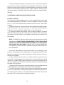
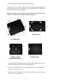
TransVision 4
™
TransVision™ 4
1.0
Printed in USA
Table of Contents
Safety Instructions .......................................................................................... 2
Introduction ..................................................................................................... 5
Processor Front Panel Controls ..................................................................... 6
Processor Rear Panel—Connections and Installation.................................. 7
Programming URC-100 Remote Control to Operate TransVision™ 4 ........ 11
Quick Reference Remote Control Operation .............................................. 12
Navigating The Control Menus ................................................................... 14
Information Menu..................................................................................... 14
Main Menu ............................................................................................... 14
Input Option. ............................................................................................ 15
Format Option .......................................................................................... 15
Video Control Menu ................................................................................. 16
Setup Options .......................................................................................... 17
Menu Timeout ................................................................................. 17
Menu Position.................................................................................. 17
Num Buttons ................................................................................... 18
Lamp Mode ..................................................................................... 18
Rename Inputs ................................................................................ 18
Rename Formats ............................................................................. 19
Screen Setup ................................................................................... 19
Image Setup .................................................................................... 19
Custom Format ................................................................................ 20
Relay Setup...................................................................................... 21
Lamp Hours ..................................................................................... 21
Projector Installation ................................................................................... 22
Physical Dimensions ................................................................................... 31
TransVision™ 4 RS-232 Control ................................................................... 32
Specifications ............................................................................................... 33
Lamp Replacement Procedure. ................................................................... 35
Warranty . ...................................................................................................... 36
1
Safety Instructions
WARNING
HAZARDOUS VOLTAGE
DO NOT OPEN
ATTENTION
COURANT ELECTRIQUE
NE PAS OUYRIR
!
CAN SHOCK, BURN OR CAUSE SEVERE INJURY OR DEATH. DO NOT
REMOVE THE TOP COVER. REFER SERVICING TO QUALIFIED PERSONNEL.
.
1. Read and apply all of the safety and operating instructions with your
video equipment.
2. Keep all safety and operating instruction for future reference.
3. Unplug this video equipment from the wall outlet before cleaning. Never
use liquid or aerosol cleaners. Use only a damp cloth for cleaning.
4. Do not use any attachments or accessories not recommended by the
manufacturer as they may cause hazards.
5. Do not use this video equipment near water. Avoid placing it near a
bathtub, kitchen sink, or laundry tub, in a wet basement, or near a swimming pool.
6. Do not place this video equipment on an unstable cart, stand, or table.
The video equipment may fall, causing serious injury to a child or adult
and serious damage to the appliance. Use only with a cart or stand recommended by the manufacturer. Wall or shelf mounting should follow
the manufacturer’s instructions, and should use a mounting kit approved
by the manufacturer.
6.1 Move any appliance and cart combination with care. Quick stops,
excessive force, and uneven surfaces may cause the appliance and a
cart to overturn.
7. Side, Top and Bottom openings in the cabinet are provided for ventilation, and to insure reliable operation of the video equipment and protect
it from overheating. These openings must not be blocked or covered.
Never place the video equipment on a bed, sofa, rug, or other similar
surface that may block ventilation openings. Never place this product
near or over a radiator or heat register. Do not place this product in a
built-in installation such as a bookcase or rack unless proper ventilation
is provided.
8. Operate only from the type of power source indicated on the marking
label. If you are not sure of the type of power supply to your home, consult your appliance dealer or local power company.
9. This unit is equipped with a three conductor polarized alternating-current
line plug. This plug will fit into the power outlet only one way. This is a
safety feature. If you are unable to insert the plug fully into the outlet,
contact your electrician to replace your obsolete outlet. Do not defeat
2
the safety purpose of the polarized plug.
10. Route power supply cords so that they will not be walked on or pinched
by items placed on or against them. Pay particular attention to cords
at plugs, convenience receptacles, and the points where they exit the
products.
11. Protect your video equipment from lightning during a storm or when it
is left unattended and unused for long periods of time, unplug it from
the wall outlet. This will prevent damage to the unit due to lightning
and power-line surges.
12. Do not overload wall outlets and extension cords as this can result in
fire or electric shock.
13. Never push objects of any kind into this video equipment through cabinet slots as they may touch dangerous voltage points or short out parts
that could results in a fire or electric shock. Never spill liquid of any kind
on the video equipment.
14. Do not attempt to service this unit yourself as opening or removing cover may
expose you to dangerous voltages or other hazards. Refer all servicing to
qualified service personnel.
15. Unplug this video equipment from the wall outlet, and refer servicing
to quali-fied service personnel under the following conditions:
15.1 When the power cord or plug is damaged or frayed.
15.2 If liquid has been spilled into the video equipment.
15.3 If the video equipment has been exposed to rain or water.
15.4 If the video equipment does not operate normally by following the
operating instructions.
15.5 Adjust only those controls that are covered by the operating instructions
as improper adjustment of other controls may result in damage and
will often require extensive work by a qualified technician to restore
the video equipment to normal operation.
15.6 If the video equipment has been dropped or the cabinet has been
damaged.
15.7 When the video equipment exhibits a distinct change in performance.
16. When replacement parts are required, be sure the service technician
has used replacement parts specified by the manufacturer that have the
same characteristics as the original part. Unauthorized substitutions
may result in fire, electric shock, or other hazards.
17. Upon completion of any service or repairs to this video equipment, ask
the service technician to perform routine safety checks to determine
that the system is in safe operating condition.
18. Do not place anything on the video equipment. Heavy objects placed
on any part of this system will cause damage.
19. WARNING: To prevent fire or shock hazard, do not expose this appliance
to rain or moisture. To prevent electric shock do not use this (polarized)
plug with an extension cord, receptacle or other outlet unless the blades
can be fully inserted to prevent blade exposure.
3
NOTE: This equipment is designed to operate in the USA, Canada and other
countries where the broadcasting system and AC house current is exactly
the same as in the USA and Canada.
IMPORTANT INFORMATION FOR THE USER/FCC STATEMENT
This equipment has been tested and found to comply with the limits for a
Class B digital device, pursuant to Part 15 of the FCC Rules. The limits are
designed to provide reasonable protection against harmful interference in a
commercial environment. This equipment generates, uses and can radiate
radio frequency energy and, if not installed and used in accordance with
the instructions, may cause harmful interference to radio communication.
However, there is no guarantee that harmful interference will not occur in
a particular installation. If this equipment does cause harmful interference
to radio or television reception, which can be determined by turning the
equipment off and on, the user is encouraged to try to correct the interference by one or more of the following measures:
• Reorient or relocate the receiving antenna.
• Increase the separation between the equipment and receiver.
• Connect the equipment into an outlet on a circuit different from that to
which the receiver is connected.
• Consult the dealer or and experienced radio/TV technician for help.
4
Introduction
TransVision™ 4 is a High Definition Digital Video Projection system comprising
of two complementary components: a High Definition Video Projector featuring
Dark Chip™ 2 Digital Light Processing (DLP™) technology from Texas Instruments and a Digital Video Processor. The TransVision™ 4 offers an outstanding
progressive scan HDTV images with 16:9 aspect ratio and 1280 x 720 (720P)
native resolution.
The TransVision™ Projector may be floor or ceiling mounted and configured
for front or rear projection.
The Digital Video Processor is designed to be located at the video sources.
It accepts a total of 10 video inputs, provides source switching, digital video
processing of analog and digital video sources and delivers a 720p digital
output to the Projector via a proprietary DVI cable.
The ten video inputs include: two HDCP compliant DVI-D; two RGB; two
Component Video; two S-Video and two Composite.
Signal connections between the Digital Video Processor and the Projector
are made through a proprietary DVI cable with a Control Signal. The Control
Signal is used to transmit bi-directional control signals (on, off, lamp status…)
between the Projector and the Processor.
An infrared learning wireless remote control with on-screen graphics selects
the input source and adjusts all of the operating controls. The system may also
be controlled from the front panel or from a RS-232 serial port.
IR sensors on both the Projector and the Processor allow the system to be
controlled from either unit.
Video and image settings for each individual video input may be adjusted
and stored separately in the system’s memory. These settings are recalled for
each input and video type when selected.
The TransVision™ 4 determines the video signal type by measuring horizontal and vertical scanning frequencies. If the video signal matches a predefined
video source, the TransVision™ 4 selects video and image settings from the
system’s memory. The predefined video sources include: 480i, 480p, 580i, 580p,
1080i, 540p, and 720p and computer sources VGA, SVGA, XGA, SXGA.
In addition to predefined video sources, the TransVision™ 4 allows the user
to create up to three new video source memory locations per video input.
For more details on how to create memory location for new video sources
refer to the “Image Setup Menu.”
Two programmable 12 volt screen trigger outputs are also provided to trigger a relay in an electric screen, projector lift, or other relay activated device.
5
Processor Front Panel Controls
The TransVision™ 4 Processor front panel controls include:
• A POWER button to turn the system On or Off.
• An indicator light (LED) which is lit when the unit is turned on and blinks when
a valid IR command is received.
— When the LED is DARK the AC power to the unit is turned off.
— When the LED is flashing On and Off, power is connected and the unit is
in the standby mode.
— When the LED is on the unit is powered on.
— When the LED is flashing fast, this indicates that the lamp failed to ignite.
If the lamp failed to ignite, the lamp may either be burned or hot. In case
the lamp is hot, wait approximately 1 minute to turn the unit on.
• An IR Receiver Window
• A MENU button to display the Main menu or to return to the previous
menu.
• Up ▲ and down ▼ FUNCTION buttons to sequences through the on-screen
menu options.
• Left ◀ and right
menu.
▶ VALUE buttons to adjust values or to move to a sub-
6
Processor Rear Panel — Connections and Installation
1
2
9
3
4
5
1. DVI/HDCP Output to Display
6
7
8
DVI-D
2. DVI/HDCP Inputs
(DVI 1, DVI 2)
DVI-D
3. Switched +12 VDC Outputs
(RY1, RY2)
2.5mm DC Plug
4. RGBS Computer/HDTV Inputs
(RGB1, RGB2)
D-sub 15 pin Socket
5. RS-232 Computer Input
(RS-232)
D-sub 9 pin Socket
6. S-Video Inputs
(S1, S2)
4 pin Mini-Din
7. Composite Video Inputs
(V1, V2)
RCA Type
8. Component Video Inputs
(Y1, R1, B1)
RCA Type
(Y2, R2, B2)
RCA Type
(AC IN)
3 Prong Receptacle
9. AC Power Receptacle
7
1. DIGITAL OUTPUT (DVI )
Connect the digital video output from the processor to the projector using
DWIN’s DVI-D cable.
Special Note about In-Wall Installations and Cable Lengths:
A standard rectangular DVI connector is fairly large in size (approximately 2”
wide) making it difficult to run through the walls. DWIN’s solution is to terminate one end of the DVI cable with a .75” circular connector that can easily run
through a 1” conduit (figure 1).
DWIN offers a series of unique (DVI-D-xx) cables in six different lengths: 25,
30, 35, 40, 45, and 50 feet. Part numbers for these cables are DVI-D-xx, the “xx”
refers to the length of the cable. Part numbers for these cables are DVI-D-xx,
the “xx” refers to the length of the cable. For cable lengths longer than 50 feet,
use DWIN’s Cable Extender. The cable extender operates with DVI-R-xx cables
and are available in 25, 35, and 50 Feet lengths
Connects to the Processor
Connects to the Projector
Fig. 1: DVI Cable with Circular Connector
2. DVI-D INPUTS
The DVI 1 and DVI 2 inputs are HDCP compliant for High-Definition (480p,
580p, 720p, 1080i) sources or computer graphics with VGA, SVGA, XGA, and
WXGA resolutions. For computer graphics with VGA, SVGA, XGA, or WXGA
it is recommended to set the computer to 60 Hz vertical frequency.
If your computer video card has DVI output, connect the DVI cable to the DVI
1 or DVI 2 inputs of the Digital Processor. Select the corresponding DVI input by
pressing “9” or “0” on the remote control, then activate the DVI output from
the computer by using computer’s display set-up menu.
8
The following are the pin assignments for the DVI-D connectors:
Pin No.
Signal Name
Pin No.
Signal Name
Pin No.
Signal Name
1
Data 2-
10
Data 1+
18
Data 0+
2
Data 2+
11
Data 1 / Shield
19
Data 0 / Shield
3
Data 2 / Shield
14
+5V Power
22
Clock Shield
6
DDC Clock
15
Ground
23
Clock+
7
DDC Data
16
Hot Plug Detect 24
Clock-
9
Data 1-
17
Data 0-
3. SWITCHED +12 VDC OUTPUTS
The TransVision™ 4 Processor has two switched +12 VDC outlets (2.5 mm DC
plug) labeled as RY1 and RY2. These outlets may be used to trigger a relay in
an electric device. Each output provides 100 ma DC current. See Relay Setup
menu for more details.
4. RGB INPUTS
The RGBS1 and RGBS2 inputs (D-sub 15) are provided for High-Definition (480p,
580p, 720p, 1080i) sources and computer graphics with VGA, SVGA, XGA, and
WXGA resolution. For computer graphics with VGA, SVGA, XGA, or WXGA it
is recommended to set the computer to 60 Hz vertical frequency.
The following are the pin assignments for the D-sub 15 pin connector:
Pin No.
Signal Name
Pin No.
Signal Name
Pin No.
Signal Name
1
Red
6
Ground
11
2
Green
7
Ground
12
3
Blue
8
Ground
13
Horz. SYNC
4
9
Ground
14
Vert. SYNC
5
10
15
5. RS-232 COMPUTER INPUT
The RS-232C serial interface is provided for external control of the TransVision™
4 from a central controller, such as a Home Theater control computer, Smart
Home automation system, etc.
For D-sub 9 pin connector pin-out and RS-232 command list, please refer
to “TransVision™ 4 RS-232 Control” section.
6. S-VIDEO INPUTS (S1, S2)
The S1 and S2 inputs are provided for NTSC (480i) or PAL (580i) video sources,
such as off-air tuners, satellite systems, cable boxes, SVHS VCR and DVD players. S-Video inputs, instead of composite video inputs, are recommended for
use with DVD players and satellite systems.
9
7. COMPOSITE VIDEO INPUTS (V1, V2)
The V1 and V2 inputs are provided for NTSC (480i) or PAL (580i) video sources,
such as off-air tuners, satellite systems, cable boxes, VCR and DVD players.
8. COMPONENT VIDEO INPUTS (Y1, Y2, Y3)
Two component video Y, Cr, Cb or Y, Pr, Pb inputs are provided for interlaced
video signals from regular DVD players (480i, 580i), progressive component
video signals from progressive DVD players (480p, 580p), and progressive or
interlaced HD signals (480p, 540p, 720p, 1080i) from HD sources. The TransVision™ 4 Processor automatically detects the resolution and configuration of the
component video signal applied to its input and processes it accordingly.
9. AC POWER RECEPTACLE
The AC power receptacle should be connected to a non-switched 120 VAC outlet
using the power cord provided with the TransVision™ 4 system.
DWIN strongly recommends that the TransVision™ 4 Projector and Processor both be connected to the same AC line circuit using a high quality surge
protector or power line conditioner.
10
Programming URC-100 Remote Control
to Operate the TransVision™ 4 Processor
The TransVision™ 4 System is shipped with a factory pre-programmed remote
control.
1.Press the TV device button.
2. Press and hold both the SHIFT and ENTER buttons for 3 seconds. The display
will blink “Set” and then “DWIN.”
3.Enter the TransVision™ 4 brand code: 177
4.Press the LIGHT button on the right hand side to complete the programming.
To operate other audio and video devices refer to the URC-100 Operating
Manual.
11
Quick Reference Remote Control Operation
DWIN
AUD
CD
DVD
AUX
SAT
TV
VCR
CBL
OFF
ON
SHIFT
PREV
CH
MUTE
VOL
CH
TV
VCR
GUIDE
INFO
MENU
EXIT
=
SELECT
1
2
3
4
5
6
7
8
9
+10
0
ENT
MODE SUB
CTR
12
REAR
LIGHT
The remote control provided with the TransVision™ 4 is a universal remote
control capable of controlling 8 different devices.
1. Select TV device to control the TransVision™ 4 System.
2. Press ON to turn the TransVision™ 4 ON.
3. Press OFF to turn the TransVision™ 4 OFF.
4. Press MENU to display the Main menu or to return to the previous menu.
5. Use the numbered buttons for direct switching of inputs.
To select a specific input, press a numbered button.
For
Press
Composite Video Inputs
1 or 2
S-Video Inputs
3 or 4
Component Inputs
5 or 6
RGB Inputs
7 or 8
DVI Inputs
9 or 0
6. Press up▲or down▼to sequence through the on-screen menu options.
7. Press left ◀ or right ▶ to adjust values or to navigate to sub-menus.
8. Press SEL to advance to a sub-menu.
9. Press EXIT to clear the on-screen menus.
10. Press ENTER to perform a selected function.
11. Press INFO to display the system status.
12. Press GUIDE to sequence through format options. Or press CTR up ▲
followed by a numbered buttons 1-4 to select format.
Numeric Button
Standard Format
HD Format
1
2
3
4
Standard
Anamorphic
Letterbox
Custom
HD
Custom
The brand code for TransVision™ 4 is 177.
13
Navigating the Control Menus
Information Menu
The Information menu reports the current status for input video source and
lamp hours used. The Information menu may be accessed when no other menu
is displayed on the screen.
Information
Input
DVI 1
Format
HD
Video Type
720p
Lamp Hours
58
1. To display the Information Menu, press INFO button on the remote control.
2. Press EXIT on the remote to clear the screen immediately.
Main Menu
The Main menu offers a choice of Input selection or Format selection, and
navigation options to Video controls and Setup functions.
DWIN TransVision™
Input
DVI 1
Format
HD
Video
Setup
1. Press MENU to display the Main menu.
2. Scroll up ▲ or down ▼ the list to highlight the desired option.
3. Press left ◀ or right ▶ to adjust values or navigate to sub-menus.
4. Press EXIT on the remote to clear the screen immediately.
The Time Out feature will automatically clear the screen unless another button
on the remote or front panel is pressed.
14
Input Option
All 10 video inputs may be selected either directly or through Input menu. To
select a video input directly, press the numeric buttons on the remote control
that corresponds to the desired input:
• For composite video inputs, press 1 or 2
• For S-Video inputs, press 3 or 4
• For component video inputs, press 5 or 6
• For RGB inputs, press 7 or 8
• For DVI inputs, press 9 or 0
Numeric Button
Input
1
2
3
4
5
6
7
8
9
0
Video 1 (composite)
Video 2 (composite)
S-Video 1
S-Video 2
Component 1
Component 2
RGB1
RGB2
DVI 1
DVI 2
To select a video input through the menu:
1. From the Main menu scroll up
option.
▲
or down
▼
to highlight the Input
2. Use the left ◀ or right ▶ buttons to sequentially select the input sources.
3. Or while the Input option is highlighted use the numbered buttons 1 through
0 on the remote control for direct switching of inputs.
Format Option
The Format option refers to the aspect ratio of the recorded video. For example,
a DVD player which is connected to the component input may be used to
playback Standard (4:3), Anamorphic or Letterbox format. Format selection is
provided for 480i, 480p, 580i and 580p video sources. For 540p, 720p and 1080i
signals, the system will automatically select HD (16:9) aspect ratio. In addition
to predefined formats, a Custom format selection is provided.
To adjust the custom format, see the Custom Format section in the
Setup menu.
DWIN TransVision™
Input
Video 1
Format
Standard
Video
Setup
Numeric Button
Standard Format
HD Format
1
2
3
4
Standard
Anamorphic
Letterbox
Custom
HD
Custom
15
1. From the Main menu scroll up ▲ or down ▼ to highlight the Format option.
This enables to select the aspect ratio.
2. Use the left ◀ or right ▶ buttons to sequentially select the aspect ratio.
3. Or use buttons 1-4 on the remote control for direct selection of Formats.
4. To change formats without entering the Main menu, Press the GUIDE button.
To access the format option directly (bypassing the Main menu), press the
GUIDE button followed by the corresponding number buttons: 1, 2, 3 or 4.
Format settings for each video input are stored separately in the system’s memory.
These settings are recalled for each input and video type when selected.
Video Control Menu
1. From the Main menu scroll up▲or down▼to highlight the Video option.
2. Use the left ◀, right ▶ or SEL buttons to advance to the Video Control
menu.
3. To access Video menu directly bypassing the Main menu, press either the
up ▲ or down ▼ button.
DWIN TransVision™
Input
Video 1
Format
Standard
Video
Setup
4. Use the up▲or down▼buttons to select the desired Video Control option.
5. Use the left ◀ or right ▶ buttons to adjust video settings.
Contrast
Video Controls
Contrast
50
Brightness
50
Color
50
Tint
50
Sharpness
5
50
Once you press the left ◀ or right ▶ buttons this menu will be replaced with
a single line. This allows you to see the picture while adjusting the control
settings.
16
6. To restore the full Video menu , press MENU, up ▲ or down ▼ buttons.
Picture setting changes made with the Video menu are saved in memory for
each of the ten video inputs. Many video sources are different enough to require this fine-adjusting and these settings will be recalled each time a video
input is selected.
Setup Options
1. From the Main menu scroll up ▲or down▼ to highlight the Setup option.
2. Use the left◀, right ▶ or SEL buttons to advance to the Setup Options menu.
Setup Options
Menu Timeout
30 sec
Menu Position
Norm
Num Buttons
Input
Lamp Mode
Std
Rename Inputs
Rename Formats
Screen Setup
Image Setup
Custom Format
Relay Setup
Lamp Hours
Menu Timeout
This feature selects the length of time before the on-screen menus are removed
from the screen.
1. Use the left ◀ or right ▶ buttons to select 15, 30, 45 or 60 seconds.
Menu Position
This feature is provided to adjust the menu location of the Digital Video Processor so that it won’t obscure the on-screen menus from your other video input
devices (DVD, cable, satellite).
DWIN TransVision™
Menu Position
1. Use all four arrow buttons ( left ◀, right ▶, up ▲, down ▼) to adjust the
menu position on the screen.
17
2. After adjusting to a desired menu position, press MENU button on the remote
to go back to the Setup menu or press EXIT button to clear the screen.
Num Buttons
This feature selects between “Inputs” and “Power On” option.
1. When “Input” is selected, use the numbered buttons 0-9 for direct switching of inputs.
2. When “Power On” is selected, use the numbered buttons 0-9 to turn the
power on and select the corresponding input.
Lamp Mode
This feature allows you to select between Standard (Std) or Low lamp operating modes.
1. When Standard (Std) is selected, the lamp will operate at full power. Select
Standard (Std) for screen sizes larger than 100” diagonal or with rooms with
high ambient light.
2. When low is selected, the lamp will operate at reduced power. Select Low for
screen sizes smaller than 100” diagonal and/or with light controlled rooms.
Rename Inputs
This feature allows you to change the names of all ten video input sources
which appear on the Main menu. A default name is provided for each input
such as Video 1.
Rename Input
Video 1
Video 1
1. Scroll up ▲ or down ▼ the default list to highlight a desired input.
2. Scroll the right ▶ cursor key to the first character in the highlighted (right
column) listing.
3. When the first character is highlighted (as shown), use the up ▲ or down
▼ cursors to scroll through the alpha numeric options.
Scrolling up ▲ starts with the letter “A” and continues to the end of the alphabet followed by numbers and punctuation marks. Scrolling down
the process in exactly the opposite order.
4. Choose a character for the first space.
5. Then scroll right ▶ again and select the next character.
18
▼ repeats
Each input name can be of 11 characters long.
6. When you have completed renaming the first input, scroll left ◀ to exit the
right column.
7. Scroll up ▲ or down ▼ the default list to repeat the process for all of the
inputs you wish to rename.
Rename Formats
A default name is provided for each format such as Standard, Letterbox,
Anamorphic, HD or Custom. To enter a different name, use the cursor to highlight Rename Formats and follow the same instructions as in the Rename
Inputs menu.
Rename Formats
Standard
Standard
Screen Setup
The Screen Setup menu is used during projector installation to position the
projected image with the screen and to select the projection mounting configuration.
1. Use the left ◀ or right ▶ button to select from the Front Floor, Front Ceiling, Rear Floor, or Rear Ceiling configurations.
The selection process has a built-in delay to perform the function, so it may
appear to be slow during executing your selections.
Screen Setup
Mounting
Front Floor
Image Setup
The Image Setup menu allows you to position and adjust the video input image size. Video image parameters vary from different video sources and may
require adjustment to properly fit the screen.
To Adjust the Video Image Size and Position:
1. Select either the H-Position, H-size, V-Position or V-size option in the Image
Setup menu.
2. Use the up▲ or down▼ buttons to set the desired image size or position.
H-Position and V-Position functions move the picture up/down or left/right
without changing the image size. H-size and V-size functions expand (or shrink)
the image size to fit on the screen.
19
Image Setup
H-Position
230
H-Size
1280
V-Position
20
V-size
535
Special Note for DVI Inputs:
DVI video signals contain image size and position information and generally
do not require adjustments. Occasionally certain DVI input sources may contain extra lines or unwanted non-picture information, typically appearing as
white horizontal lines along the top of the picture. To eliminate this unwanted
information, you should use the Image Setup function to adjust the image
position or size to remove these lines.
1. In the Image Setup menu, select the Adjust option = On and adjust the image as described in the Image Setup menu.
Unless you have this specific unwanted non-picture information with DVI
sources, DWIN recommends leaving Adjust option OFF.
Image Setup
Adjust
Off
Image Setup
Adjust
On
H-Position
230
H-Size
1280
V-Position
20
V-size
535
Custom Format
The Digital Video Processor gives you Standard, Letterbox and Anamorphic
preset formats for 480i, 480p, 580i and 580p video sources and HD (16:9) preset
format for 540p, 720p and 1080i video sources.
Video sources recorded in a 4:3 aspect ratio will appear with black bars
along the left and right sides on the screen. To reduce or eliminate these black
bars, you can use the Custom Format function. The H-Size function allows you
to stretch the picture width to fill the entire display. The V-Size function allows
you to expand the top and bottom of picture to maintain the proper aspect
ratio of the picture.
HD video sources recorded in a 2.35:1 aspect ratio will appear with black
bars along the top and bottom of the screen. To reduce or eliminate these black
bars, you can use the Custom Format function. The V-Size function allows you
to stretch the picture height to fill the entire display. The H-size expands the left
20
and right sides of picture to maintain the proper aspect ratio of the picture.
For Custom Format Menu:
1. Scroll down to select ‘H-Size’ or ‘V-Size’.
2. Use the left ◀ or right ▶ buttons to set the desired image size.
Custom Format
H-size
1365
V-size
180
Relay Setup
The Relay Setup allows you to assign the TransVision™ 4’s RY1 and RY2 screen
trigger outputs to particular aspect ratio for to activate various accessories or
controls in a home theater.
Relay Setup
Relay 1
Off
Relay 2
Off
Off
Power
4:3
16:9
Relay is off.
Relay is on when the unit is on.
Relay is on when 4:3 Aspect Ratio is selected.
Relay is on when Anamorphic, LetterBox or HD Aspect Ratios
are selected.
Lamp Hours
The Lamp Hours must be set to 0 when a bulb is replaced.
To Reset the Lamp Hours:
1. Scroll down
▼ to highlight the Reset Tool option.
2. Use the left ◀ or right ▶ buttons to advance to the Reset Lamp Hours
menu.
3. 2. Use the left ◀ or right ▶ buttons to highlight “Yes.”
4. Press ENTER
Reset Lamp Hours
Lamp Hours
Total Hours
Highlight “Yes” and press
0
“Enter” to reset
Reset Total
No
21
Yes
Projector Installation — Introduction
Physical and electrical installation of the TransVision™ 4 must be performed
only by a trained professional who is knowledgeable about both the specifics
of the TransVision™ 4 and the requirements of the local building and electrical
codes.
Physical installation of the TransVision™ 4 may be divided into 3 steps:
(1) Pre-installation planning, which includes plotting the projector-to-screen
distance. This requires knowledge of the screen size and placement. From
this step you will determine where the projector is located.
For throw distance calculation and physical mounting dimensions, please
refer to the customer support section at www. dwin.com.
(2) Preparation and Installation of the ceiling mount bracket, including
drilling holes, securing the bracket to the ceiling and assembling the
mounting hardware.
(3) Final Adjustments.
Once the physical installation is complete, the unit should be properly
adjusted.
Focus: Use the front ring of the lens.
Positioning: Use three dimensional physical adjustments made possible
by the mounting hardware.
Size: Use the zoom ring of the lens;
Vertical Offset: The vertical offset is fixed and may be calculated from the
following formula: Offset = .081 x W +4.5”. The calculation includes DWIN’s
2 inch Ceiling Mount Bracket. Please refer to the “projector calculator” section under “customer support” at www. dwin.com.
(1) PRE-INSTALLATION PLANNING
A. Screen Considerations
Although the following advice is no substitute for a dealer’s recommendation
for your home, here are a few guidelines for creating a front projection home
theater that should be helpful to your early planning:
A1. Screen Color and Material:
Because the superior design and quality of DWIN’s proprietary optical system
results in excellent contrast and black levels, images will look best when
projected on a matte white screen from a reputable manufacturer. Many
competing projector companies recommend gray screens but a properly
projected picture will always look better when colors are balanced for white,
just like in a movie theater.
22
Projectors with fixed-pixel imaging arrays, such as DLP or LCD, are not
recommended for use with perforated screens. Perforated screens have
highly regular microscopic patterns that conflict with the equally uniform
pattern in the digital image array. This creates interference, a visual artifact
called a “moiré” pattern, which compromises picture quality.
To eliminate light spill, a black felt border is also recommended to enhance
the viewing experience.
A2. Screen “Gain”:
Projection screens do not generate light; they only reflect projected light.
Therefore screen gain refers to relative reflectance to a reference standard.
The most common reference standard is Magnesium Carbonate (MgCO3).
DWIN recommends a screen “gain” of 1 to 1.3.
A3. Screen Dimensions and Position
You should consult your authorized DWIN dealer or professional installer for
his or her recommendation. Most screen manufacturers and theater designers agree that screens should be installed to create a comfortable viewing
angle from a SEATED position. Here are some general guidelines:
• A screen should be wide enough to allow viewers to immerse themselves
in the program without having to move their heads from side to side. As
a rule of thumb, the viewing distance should not be less than two times
the screen width. For example, if your home theater has a 100-inch wide
screen you should have your seats installed no closer than 200-inches
from the screen.
• When specifying screen width, remember to allow enough space on the
wall for left and right front speakers, and for the screen to blend with
the aesthetics of your theater environment. Choose a dark, neutral color
(and matte, non-reflective) background wall surface. Bright wall colors or
reflective decorations can be distracting and could alter the appearance
of the image.
• A screen should be installed high enough to allow a comfortable viewing angle for people sitting in the front row. Eye level (from the seated
position) should be approximately 1/3 of the screen’s height measured
from the bottom of the screen.
• Your Authorized DWIN Dealer or Custom Installer should be able to consider
all your home theater design needs and provide you with professional
recommendations to enhance your investment.
23
B. Mounting and Throw Distance Calculation
Before starting the installation you will need to calculate the projector throw
distance and the ceiling to top-of-picture offset. The throw distance and the
precise center of the screen are then used to determine the exact location for
the physical installation of the projector.
��������������
�
�
������
������
�
������
The TransVision™’s zoom lens allows for a wide range of throw distance options — the distance from the projector to the screen. For maximum flexibility
in adjustment we recommend that, where possible, the projector be installed in
the middle range of the possible distances. However, the unit may be installed
at any point within the allowable range.
• To obtain the minimum throw distance, multiply the screen width by 1.65.
• To obtain the maximum throw distance, multiply the screen width by 2.08.
C. Screen Offset
Screen offset is the distance between the top of the picture area of the screen
and the ceiling. This distance is important and it should be calculated before
the screen is installed to ensure proper positioning of the projector in relation
to the screen. Incorrect screen offset may cause image keystone distortion and
cannot be compensated either with the mounting system or electronically.
The TransVision™ 4 is a 16:9 Projector and is designed to be used with a 16:9
screen.
• The screen offset is fixed and may be calculated from the following
formula: Offset = .081 x W +4.5”. The calculation includes DWIN’s 2 inch
Ceiling Mount Bracket.
• Please refer to our TransVision™ 4 Calculator, under the Customer Support section at www.dwin.com for assistance with calculating these
dimensions.
NOTE: The ceiling mounting system enables you to make small adjustments
to the vertical tilt without introducing visible keystone distortion.
24
For floor-mounted installations the picture offset is the distance between
the mounting surface of the projector and the bottom of the picture. In order
to deliver pictures that are free of keystone distortion, be certain to calculate
the offset distance before ordering screens and/or cabinetry. Although some
adjustment range is available in floor mounted systems by using the adjustable feet.
(2) PREPARING FOR CEILING MOUNT INSTALLATION
2A. Cable Installation
The TransVision™ 4 digital video processor sends a high definition video signal
via a DWIN-proprietary DVI-D cable. For easy installation in walls, the cable
has a ¾” inch round connector that connects to the front (lens side) of the
projector.
DVI cables (with the ¾” round connector) are available from DWIN in lengths
of 25-feet to 50-feet in five-foot increments. A separately sold DVI Cable Extender box is also available to support cable runs of up to 100-feet.
In new home theater construction, many installers choose to install the
DWIN DVI cable during the pre-wiring phase when beams and crawl spaces
are readily accessible. Cables can be ordered several months in advance for
this purpose.
NOTE: The DWIN DVI cable must be used to connect the projector and the
video processor. DWIN STRONGLY RECOMMENDS TO RUN THE DVI CABLES
THROUGH A 1-INCH OR LARGER DIAMETER CONDUIT. A CONVENTIONAL
DVD-D CABLE WILL NOT WORK. FURTHER, DUE TO SIGNAL-DEGRADATION ISSUES, A CONVENTIONAL ‘GENDER CHANGER’ ADAPTOR IS NOT
RECOMMENDED.
Do not coil, tightly bend or crimp the DVI cable; it may damage or short
the wires and compromise the shielding. Do not straddle staple the DVI cable.
Doing so may puncture the cable, damaging or shorting the wires and compromise the shielding.
During installation inside walls, care should be taken to avoid excessive
strain which may damage to internal cable wires. When the DVI cable is being
“pulled” or “snaked” DWIN recommends that the snake be connected as far
down the length of the DVI cable as possible to prevent stretching damage to
the cable or the connector.
Further, the DVI-D connector is extremely delicate. Care should be taken to
avoid dropping the connector on hard surfaces to avoid damage.
To prevent interference, DWIN strongly recommends that the DVI cable not
be run in close proximity or tied to any AC power lines! DWIN strongly recommends that the DVI cable be run through a dedicated (DVI cable only) conduit
that meets NEC or local electrical code requirements.
25
2B. Ceiling Mount Preparation
Once the throw distance has been calculated and the screen installed, the
next step in the installation is to locate the precise mounting position of the
projector.
The ceiling mount bracket must be aligned to the middle of the screen and
located as close as possible to an electrical source AND a support beam. If
the projector is not located properly, it is not possible to compensate for any
resulting “keystone” distortion in the projected image.
IMPORTANT NOTES:
1. Before proceeding further with the installation, make certain that video signal/
control wiring and AC power have been run to the projector location. Keep
in mind that the connections to the projector are at the back of the unit.
2. In rooms where the projector is mounted near a rear wall, be sure to allow
adequate clearance for proper ventilation. Allow at least 24” of rear-facing
clearance. (See Figure 2). Improper ventilation is a cause the TransVision
projector to overheat, shortening lamp life and reducing the reliability of
electronic components. Projector failures due to overheating will invalidate
the manufacturer’s warranty.
Mounting Close to the Back Wall
CEILING
EXHAUST
BACK WALL
DIGITAL INPUT
120 VAC
INTAKE
24” MIN
Figure 2
3.When the unit is mounted inside a cabinet, be certain that an exhaust vent is
provided so that the hot air generated by the projector may be safely removed
from the cabinet. DO NOT RECIRCULATE AIR FROM WITHIN THE CABINET.
Failure to properly design an enclosure will cause projector overheating,
resulting in premature lamp failure and wear of electronic components. See
Figure 3
Enclosed Ceiling Mount
EXHAUST FANS
DIGITAL INPUT
120 VAC
INTAKE
ENCLOSURE
Figure 3
26
2C. Ceiling Mount Installation and Projector Mounting
The optional ceiling mount kit (CMB) consists of three parts. Before beginning
the installation process, first identify each of the three parts of the mounting
system as shown in the pictures below.
NOTE: The ceiling must be capable of safely supporting the weight of the
projector and mount, which is approximately 25 pounds.
B2
C2
A2
B1
A1
Ceiling Bracket A
C1
Ceiling Mount Kit
Ceiling Bracket B
Ceiling Assembly C
Do Not Remove Hex Nuts!
1. Disassemble the Ceiling Mount Kit by removing and saving the two rear hex
screws located on both sides of the Ceiling Mount Kit.
2. Loosen the middle two hex screws and slide out from the “L” shaped groove
brackets “A” and “B” as a unit.
3. On bracket “A”, remove and save all four hex head screws and separate
bracket “A” from bracket “B”.
27
Ceiling Mount Kit Installation continued
4. Mount ceiling bracket “A” to the ceiling, making certain that the “FRONT”
label faces the screen.
5. Place bracket “B” inside bracket “A” and then secure the two pieces together
using the four hex head screws, making certain that the “FRONT” label faces
the screen.
6. Turn the projector upside down and place ceiling assembly C over the bottom of the projector, with the “FRONT” label facing toward the lens. NOTE:
DO NOT ATTEMPT TO LOOSEN THE FIVE HEX NUTS ON THE CEILING ASSEMBLY “C”, THEY ARE SEALED!
7. Use provided four 0.4” countersink screws to attach the ceiling assembly
“C” to the projector.
8. Raise the assembly “C” and the Projector as a unit and hang from bracket
”B” by sliding two center side screws on bracket “B” into the “L” shaped
groove at the outer edges of the assembly “C” mounting bracket. Secure
the two assemblies together using the hex screws on the left and right sides
of the projector.
The projector is now suspended from the ceiling mount bracket.
28
2D. Connecting the TransVision™ 4 System
LED
A. Connect AC power receptacle to a non-switched 120 VAC outlet using
the power cord provided with the TransVision™ 4 system.
B. Connect the digital input to the TransVision™ 4 processor using the circular connector of DVI cable.
NOTE: The TransVision™ 4 requires the use of a DWIN DVI cable between
the Projector and the Digital Video Processor to operate correctly !
C. The IR Receiver and the Power LED are located on top of the projector.
D. The POWER LED is a multi-purpose indicator:
• When the LED is dark the AC power to the unit is turned off.
• When the LED is flashing on and off, power is connected and the unit
is in the standby mode.
• When the LED is on the unit is powered on.
• When the LED is flashing fast, the projector lamp failed to ignite. The
lamp may have failed or overheated. In case the lamp is hot, wait approximately 1 minute to turn the unit on. If the lamp has failed, contact
your DWIN dealer or DWIN for a replacement.
29
(3) FINAL ADJUSTMENTS
After the physical mounting is complete, horizontal and vertical adjustments
can be made to center and align the projected image to the screen.
Before making these adjustments you should:
1. Turn the system On.
2. Adjust the zoom and focus. Use the On-Screen Menus to help refine focus.
3. Once on screen menus can be clearly viewed, go to Screen Setup menu.
4. Make the following horizontal and vertical adjustments to align the white
field pattern to the screen.
• To move image left or right, loosen both the C1 and C2 hex head screws on
ceiling bracket C. To shift the image to the left, tighten the hex screw on the
right side. To shift the image the to the right, tighten the hex screw on the
left side. Once desired position is obtained, tighten both screws.
• To level the projector front/back, loosen both the B1 and B2 hex head screws
on ceiling bracket B. Tilt/level projector to desired position and once desired
position is obtained, tighten all hex screws.
• To align image parallel to the screen, loosen the A1 and A2 hex head screws
on ceiling bracket A and level the projector. Once image is aligned, tighten
all four hex screws.
• To align image parallel to the screen, loosen the two hex screws on the
front and rear (A1/A2) of the ceiling bracket A and level the projector. Once
image is aligned, tighten all four hex screws.
30
Physical Dimensions — TransVision™ 4
2.0”
4.5”
14 ”
AC Input & Circular Connector
4.5”
A
5.2”
A
“A” CEILING MOUNT HOLE LOCATION
13.5”
4.5”
4.50“
11.0“
A
A
2.50“
4.50“
7.10“
12.60“
Projector Bottom View
31
TransVision™ 4 RS-232 Control
The RS-232 interface for the TransVision™ 4 System can be operated from any
terminal, such as a Windows based PC running HyperTerminal.
Communication Port Set-Up Connector pin-out
Baud Rate:
Parity:
Stop bits:
Num. of bits:
Flow control:
9600
none
1
8 bits
none
3
2
5
TX (Transmit Data)
RX (Receive Data)
GND (Signal Ground)
Each command is enclosed in the [ ] character envelope.
Note: Sequential commands must be separated with proper delays.
Any command followed by POWER ON must be delayed 10 seconds.
Any command followed by INPUT SELECT must be delayed 1 second.
The following table lists the commands available:
[LH]
Lamp Hours
Transmits Lamp Hours in ASCII characters.
POWER CONTROL
INPUT SELECT
[PON] Power on
[POFF] Power off
[I1]
[I2]
[I3]
[I4]
[I5]
[I6]
[I7]
[I8]
[I9]
[I0]
ASPECT RATIO SELECT
[S1]
[S2]
[S3]
[S4]
Standard (4:3)
Anamorphic or HD
Letterbox
Custom
RELAY CONTROL
[Y1ON]
[Y1OFF]
[Y2ON]
[Y2OFF]
RY1 on
RY1 off
RY2 on
RY2 off
32
Video 1
Video 2
S-Video 1
S-Video 2
YCrCb 1
YCrCb 2
RGB 1
RGB 2
DVI 1
DVI 2
Projector Specifications
Display Device
1280 x 720 DarkChip™ 2 DMD
Number of Pixels
921,600
Screen Configuration
Front or Rear throw
Mounting
Floor or Ceiling
Zoom Range
1.26:1
Image Size
60 to 200 inch Diagonal
Throw Distance
1.65 to 2.08 times Screen Width
Projection Offset
“Fixed” 14.4% of Picture Height + 4.5”
Light Source
250 Watt VIP Lamp
Lamp Life
2000 Hours
Contrast
3000:1
INPUTS
DVI
Proprietary Digital
AC Power
3 Prong Receptacle
Power Source
100-130V AC, 50/60 Hz
Power Consumption
300 Watts (2 Watts Standby)
Dimensions WxHxD
11 x 11.25 x 4.5 inch
Weight
14 lbs
Cabinet Color
Dark Gray
OPERATING CONDITIONS
Temperature
50° - 90° F / 10° - 32° C
33
Digital Video Processor Specifications
Video Systems
HDTV / DTV / NTSC / PAL
Scanning Formats
480i, 480p, 540p, 580i, 580p, 720p, 1080i
PC Signals
VGA / SVGA / XGA / SXGA
INPUTS
DVI
2 x DVI-D with HDCP
Component
2 x RCA, Y: 1 Vp-p / 75 ohm
Pb Pr: 0.7 Vp-p / 75 ohm
S-Video
2 x 4 pin Mini-Din
Y: 1 Vp-p / 75 ohm
C: 0.286 Vp-p / 75 ohm
Composite
2 x RCA: 1 Vp-p / 75 ohm
RGB/PC
2 x HD-15 Pin
RS-232 Serial
1x D-9 Pin, RS-232 Compatible
AC Power
3 Prong Receptacle
OUTPUTS
DVI
1 x DVI-D with HDCP
12V Triggers
2 x 2.5mm DC Plug
Power Source
100-130 VAC
Power Consumption 25 Watts
Dimensions WxDxH 17 x 12.75 x 3.5 inch
Weight
18 lbs
Cabinet Color
Black
INCLUDED ACCESSORIES
• Two 3 Prong Power Cables
• 8 Device Preprogrammed Remote Control
• User’s Manual
OPTIONAL ACCESSORIES
• Replacement Lamp
• Ceiling Mount Kit with Three Dimensional Tilt Adjustments
• 19 inch Rack-mount Kit for Controller
• Proprietary Digital Cables Connecting Video Processor to the Projector: 25’, 30’, 35’, 40’, 45’
and 50’
• DVI Cable Extender (up to 100’)
34
Lamp Replacement Procedure
CAUTION!
Take the following precautions to prevent electric shock, burns and injuries
from broken glass.
The projection lamp operates at very high pressures and temperatures. Some
lamp failures may result in the projection lamp shattering. To prevent injuries
from shattered glass, use caution when removing the lamp assembly from its
housing. Do not touch the lamp with bare hands
For lamp replacement, turn off the power, unplug the AC cord, allow lamp
at least 30 minutes to reach room temperature.
To Replace Lamp:
External Plastic Cover
1. Remove two bottom screws to remove the plastic cover.
Lamp Assembly
Screw
>
<
CAUTION!
LAMP IS HOT
Handle
CAUTION!
LAMP IS HOT
Lamp Connector
Lamp Connector
2. Gently loosen but do not remove the top middle screw indicated by the
arrows.
3. Use the handle to pull the lamp assembly out of housing.
4. Insert new lamp assembly into housing. Note the location of the lamp connector and insert the lamp assembly in the proper direction.
5. Gently tighten top middle screw.
6. Replace plastic cover and fasten bottom two screws.
35
Limited Warranty
This warranty applies only to the first person or entity that purchases the TransVision™ 4 for personal or business use and not for the purpose of distribution
or resale. The warranty period is for one (1) year from the date of purchase for
labor and parts.
DWIN Electronics shall not be liable or in any way responsible for any incidental or consequential damages of any kind. This warranty covers all defects
in material and workmanship when shipped in its original container, with the
following specific exceptions. These are:
• damage to or deterioration of any accessory or decorative surface;
• damage caused by accident, unreasonable use or neglect, specifically
if a projector is overheated due to an improperly ventilated cabinet or
secondary enclosure;
• damage caused by improper installation or adjustment;
• damage caused by accident, unreasonable use or neglect;
• damage from failure to follow instructions contained in your operating
instructions;
• damage from the performance of repairs by someone not authorized by
DWIN Electronics;
• any unit on which the serial number has been effaced, modified, or
removed;
• damage occurring during shipment; and
• units which have been altered or modified in design, appearance or
construction.
This warranty covers only the actual defects within the PRODUCT itself,
and DOES NOT cover the costs of installation or removal from a fixed installation, normal set-up or adjustments, claims based on any misrepresentation
by the seller, or performance variations resulting from installation related circumstance such as signal quality, AC power or incompatibilities with source
devices or software.
This warranty specifies the acceptable image quality standards of the Digital
Micromirror Device (DMD) technology of the TransVision™ 4 DLP™ projector for
warranty coverage.
Definition of DMD Defect:
• Dark Pixel: A dark pixel is a single pixel or mirror that is non-functional
(stuck) in the OFF position.
• Bright Pixel: A bright pixel is a single pixel or mirror that is non-functional
(stuck) in the ON position.
• Unstable Pixel: An unstable pixel is a single pixel or mirror that does not
operate in sequence with parameters loaded into memory. The unstable
pixel appears to be flickering asynchronously with the image.
Acceptable Criteria:
• Dark Pixel – No more then 4 dark pixels.
• Bright Pixel – No bright pixels.
36
• Unstable Pixel – No unstable pixels.
DWIN Electronics will, at its option, either repair or replace the defect, or
replace the defective product or part thereof at no charge to the owner for parts
and labor covered by this warranty. If a unit is examined which is not in need
of repair, you will be charged for the examination and return shipping.
You must pay shipping charges incurred in getting your product to the
factory. We will pay the return shipping charges if the repairs are covered by
the warranty. Please save the original shipping carton. A charge will be made
for an additional carton.
If your product needs service, you should notify us at:
SERVICE DEPARTMENT
DWIN Electronics, Inc.
710 North Mariposa Street, Burbank CA 91506
Tel: ( 818 ) 239–1500, Fax: ( 818 ) 239–1506 E-mail: [email protected]
NOTE: You will need to present the original bill of sale to establish the
date of purchase.
Limited 90-Day Warranty – Projector Lamps
TransVision™ 4 lamps are rated for up to 2,000 hours of use during which the
lamp brightness may drop to 50 percent of the original brightness.
Actual projector lamp service life varies greatly depending upon several
factors such as duration of each projector session, frequency of on/off switching, environmental conditions, presence of adequate projector ventilation, etc.
The specified 2000 hour lamp life rating is not guranteed in any way.
DWIN warrants its projector lamps for 90 days from the original date of
consumer purchase.
DWIN Electronics shall not be liable or in any way responsible for any incidental or consequential damages of any kind.
This warranty covers all defects in lamp material and workmanship for 90
days from the date of lamp or projector purchase with the following specific
exceptions. These are:
• damage caused by improper installation or adjustment;
• damage caused by accident, unreasonable use or neglect, specifically
if a projector is overheated due to an improperly ventilated cabinet or
secondary enclosure;
• damage from failure to follow instructions contained in your operating
instructions;
• damage from the performance of repairs by someone not authorized by
DWIN Electronics;
• any unit on which the serial number has been effaced, modified, or
removed;
• any failed lamp with a serial number that does not match the serial number
associated with the projector
37
• any failed replacement lamp with a serial number that does not match the
serial number of the replacement lamp.
• damage occurring during shipment;
• units which have been altered or modified in design, appearance or
construction.
To make a warranty claim on any lamp, you must contact DWIN Electronics and purchase a lamp using a credit card, check or money order:
SERVICE DEPARTMENT
DWIN Electronics, Inc.
710 North Mariposa St., Burbank, CA 91506
Tel: (818) 239 – 1500, Fax: (818) 239 – 1506
Warranty Procedure for Replacement Lamps
To receive a replacement lamp, even under warranty claims, you must first
purchase a replacement lamp from DWIN Electronics. Order forms are available on the DWIN website.
If the projector lamp failed within 90 days of purchase you are entitled to
make a warranty claim. To make a claim, you must return the failed lamp to
DWIN for inspection and provide a copy of your original receipt. The serial
number on the failed lamp must match the serial number on file with DWIN
and you will receive a refund of your purchase price, either as a credit to your
credit card bill or as a check. Credits or checks will be issued within 30-days
from when the lamp was received for inspection.
38