1
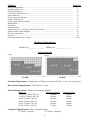
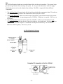
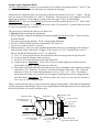
04/98 INSTRUCTION BULLETIN & MAINTENANCE MANUAL FOR CTD MODEL A480E CTD MODEL NO: CTD SERIAL NO: MANUFACTURE DATE: DISTRIBUTOR PURCHASED THROUGH: (IF ANY) CTD MACHINES, INC. 2300 East 11th Street · Los Angeles, CA 90021-2817 Tele (213) 689-4455 FAX (213) 689-1255 e-mail: [email protected] · World Wide Web: http://www.ctdsaw.com SUBJECT PAGE NO. Machine Requirements............................................................................................................................ Installation and Set-Up............................................................................................................................ Electrical Installation............................................................................................................................. General Operating Instructions................................................................................................................ Safety Instructions.................................................................................................................................... How to Operate the Machine.................................................................................................................... Safeties and Interlocks.............................................................................................................................. Setting Length Adjustment Block............................................................................................................. Manual Mode............................................................................................................................................ Trial Mode................................................................................................................................................. Automatic Mode........................................................................................................................................ Repair and Service -- PLC Input/Output Test Procedure.......................................................................... Spindle and Pivot Shaft Diagrams............................................................................................................ Preventive Maintenance............................................................................................................................ Parts List.................................................................................................................................................... Electrical Schematic and Air Logic.......................................................................................................... 2 3 4,5 5 12 13 16 17 18 19 20 21 26 27 28 29,30 Machine Requirements: MODEL NO:_________________ SERIAL NO:_________________ Cutting Capacities Height Height 16 Blade Width 20 Blade Width Pneumatic Requirements: (if applicable) 4 CFM per 10 strokes at 85 PSI (.11 cubic meters at 5.98 kg/cm2) Dust Collection Requirements: 1200 CFM at 6 outlet Electrical Requirements: Based on one motor per machine Motor Size Required Amerage 7-1/2 H.P. 3 Phase, 230 Volt 20 amps 7-1/2 H.P. 3 Phase, 460 Volt 10 amps 10 H.P. 3 Phase, 230 Volt 26 amps 10 H.P. 3 Phase, 460 Volt 13 amps 15 H.P. 3 Phase, 230 Volt 34 amps 15 H.P. 3 Phase, 460 Volt 17 amps Cutting Tool Requirements: Heavy, rigid plate blades. 16 blades: .150 plate 20 blades: .180 plate -2- Breaker Needed 30 amp 20 amp 40 amp 20 amp 50 amp 30 amp Space Requirements Installation and Set Up: The CTD saw you have purchased is designed to cut wood, aluminum, plastic and steel, with of course the proper blade and conditions. For the material you are cutting, please refer to the cutting instructions for each material type. The A480E machine uses a NEMA 213T or 215T, 7-1/2 H.P., 1725 RPM, 60 Hertz TEFC Motor. CTD uses a speed-up so that the blade will run at approximately 12,500 SFPM on a 16 blade and 14,000 SFPM on a 20 blade. IMPORTANT: Before operating saw, please be sure to read the SAFETY INSTRUCTIONS TO THE OPERATOR (see Page No. 11). Note: The floor stand must be shimmed, leveled and bolted to the floor, or framed in to eliminate vibration. Use holes provided in bottom of floor stand. All machines have been completely assembled at the factory, then disassembled for shipment. Assembly of Roller Conveyor (if purchased): 1. Attach Roller Conveyor leg to bottom rear of Roller Conveyor Frame 2. Attach Roller Conveyor Frame to angle supports on main frame for A480E Saw. 3. Place seven rollers into Roller Conveyor Frame by pushing in spring loaded hex stud. 4. Top of rollers must be flat with the table top of the machine or parts will be entering the feeding mechanism at an angle, causing irregular cuts. -3- Blade Installation: Before setting blade on spindle, shut off or disconnect air supply. With the motor off and power disconnected, open left door on machine. 1. Remove spindle nut and flange. Push down with a wrench. 2. Place blade on spindle with tips pointing down. Make sure slinger and blade surface are CLEAN before putting blade on spindle. A. The blade must ALWAYS rotate to the rear of the machine on the underside of the blade (see Diagram D). Always check rotation before cutting a piece of material. 3. Replace flange and nut as before and tighten (see Diagram B). Pull up with wrench. Do not overtighten. Snugging the blade is all that is necessary. Diagram B Diagram D VOLQJHU EODGH IODQJH DUP FDVWLQJ VSLQGOH QXW VSLQGOH These machines are general purpose in their design, therefore the user should attach any additional guarding to the blade guard or table base if the cutting application causes unsafe blade exposure. This label is attached to the blade guard. Never put hand or fingers near or under the moving blade. Use a piece of wood to remove short pieces from saw. Air Supply: Bring an air supply to the machine (85 PSI @ 5.98kg/cm2) and connect to the air inlet of the main air shut off valve, located on the left side of the machine. The machine will not function without the air supply valve opened. A pressure switch, located in the control panel senses when the air supply has been opened. Do not adjust pressure switch 1, located in control panel. Electrical: The A480E machine uses a 7-1/2 H.P. 3 phase 1725 RPM, 60 Hz TEFC Motor. A disconnect switch should be provided and the machine disconnected before blades are mounted, or at any time the machine is serviced, or the blade is exposed. For motor protection against voltage fluctuations, a Magnetic Starter is provided. This starter protects the motor from overheating and will not allow the motor to restart by itself after power outages. To start motor, push the ON button located below the selector switches on the front of the machine. Bring incoming power lines to pull box located at the rear of the machine. Connect power lines to wires provided. All other wiring is complete. -4- Electrical Installation of Power to Starter by a Qualified Electrician: All wiring from the motor to the starter has been completed and tested at the factory several times. The voltage has been clearly tagged. DO NOT CONNECT ANY VOLTAGE THAT IS DIFFERENT THAN THE TAGGED VOLTAGE, AS THIS MAY CAUSE SEVERE DAMAGE AND DANGER. Consult the factory is any changes are needed. Bring power lines to the connection pull box, located at the rear of the machine and connect incoming power lines. Use dust proof connectors only. See Wiring Diagram for Three Phase Motors below. Green ground wire must be grounded to enclosure (pull box). Be sure to check rotation as polarities may be different. The blade must rotate down and to the rear on the underside of the blade (see Diagram D on Page No. 4). If a change in rotation is necessary, reverse any two of the incoming power wires. Example: If the blade is running backwards and incoming wires are connected White L1, Black L2, and Red L3, switch the Black wire with the Red so that Black is connected to L3 and Red is connected to L2. This will change the motor to rotate properly. Motor Load Amperes Motor Size 7-1/2 H.P., 3 Phase 10 H.P., 3 Phase 15 H.P., 3 Phase 208 Volt 21.5 amps 28 amps 37.5 amps 230 Volt 20 amps 26 amps 35 amps 460 Volt 10 amps 13 amps 17-1/2 amps Three Phase Motor Wiring Chart 230 Volt 460 Volt Terminal T1 T2 3&9 2&8 1 2 T3 1&7 3 Connect Leads 4,5,6 6&9 Connect Leads ---5&8 Connect Leads ---7&4 General Operating Instructions for CTD Model A480E 16 & 20 Automatic Saw: CTD Cut-Off Saws are designed for efficient, safe operation. Basic principles must be employed that are easily understood. Guarding: The belt drive is completely enclosed with a fabricated guard. The blade guard covers only the back of the blade. The left and right hinging doors must be closed and locked before any cutting should take place. The doors are adjustable up and down for different heights of material. It is essential that no more of the blade be exposed than necessary. The operator must not be exposed to an unguarded blade. The hands or fingers must never be allowed to come in close proximity to the bladefor certain, never under the blade. Cut off pieces that are short must be removed with a piece of wood or an air blast. -5- Fences or Back Stops: The CTD A480E saw is provided with accurately machined fences. This feature allows the operator to easily adjust the position of the fences for the best, safe condition. (see Position of Work below). It is essential that all fences be adjusted front to back, in the same plane. The fences must also be adjusted so that the shortest cut off piece will not be able to slip between the blade and fence. Likewise, short pieces must not be allowed to slip between the blade and the slot in the base. Danger to the operator and blade may result if either of these situations are allowed to occur. Position of Work: The fences must be set so that the centerline of the work is either to the front or on the centerline of the blade. If the work is cut on, or to the front of the centerline of the blade, the machine is absolutely safe even if the motor is overloaded and the blade is stalled. The action will drive the work down and to the rear. If the material is set behind the centerline, there is a chance of the material being lifted up by the cutting action. Material Not Flat on Table: It is necessary that the material lay flat on the table. If long material is to be cut off, the conveyor or work supports must be in exact alignment with the top of the table. If the stock supports are above or below the table, the material will bind the blade, slip or rise up as it is being cut. All back stops or fences must be in the same plane, or when the material is cut, it may tend to slip or move, causing inaccurate cuts. Clamping and Work Slippage: The work must never be allowed to slip as it is being cut. Due to the wide variety of work, clamping requirements vary considerably. Clamping: In the cutting of aluminum extrusions, often times thin legs or projections must be properly supported to avoid vibrations. Also, round materials must be securely clamped. Jaws for the vise clamps may be shaped to fit the contours of the individual piece, thus eliminating clamping and feeding problems. The rear jaws of the A480E vises have three positions. The front and rear jaws can be set 12 apart at the widest setting. The positioning of the front jaws is limited by 3 travel of the cylinder shafts. However, they are adjustable another 3 in slots using lock down bolt. (See Diagram C #123 on Page No. 28). Adjusting Rear Vise Jaws: The work, piece and feed vise rear jaws are movable 6 in doweled holes and lock down bolts. There are three different positions. If cutting smaller material, it is always best to cut to the front on the blade. To move rear fence jaw; 1. Remove lock down bolt. 2. Move rear fence angle to desired position using doweled holes. 3. Replace lock down bolt and tighten. IMPORTANT!!! A bent stock compensator is built into the Model A480E. This system allows the rod assembly to float or adjust if material is warped or bent about 3/16 on hardened pins. When changing position of the feed vise rear jaw, move entire rod assembly front to rear to check if movement is free. -6- Adjusting Front Vise Jaws: There are three vises for holding the material on the Model A480E.. They are; 1. C2, Feed Vise 2. C3, Work Vise 3. C4, Piece Vise To adjust Front Vise Jaws: A. Shut off air supply. Loosen clamp stop blocks (No. 144, & 144B on Diagram C, Page No. 27). B. Place material to be cut between clamp jaws. Push the jaws closed so that they contact the material. 1. If necessary, loosen work and piece vise lock down bolt (No. 146 on Diagram C). This will allow vises to move forward. 2. Repeat for Feed Vise (No. 144A on Diagram C, Page No. 27). C. Now, move clamp stop blocks (No. 144 & 144A on Diagram C) back towards cylinder head. Lock the clamp stop blocks and leave about 3/16 clearance between the cylinder head. Vise jaws will now move only a little, helping to secure the material between jaws and saving wasted time and motion. D. Pressure regulators are provided inside the front door. This adjustment of the vising air pressure may be necessary when cutting very light, thin walled extrusion. E. See Cutting Short Pieces below. Cutting Short Pieces: When cutting of pieces less than approximately 2 long, the front jaw insert must be relieved so that only the piece being cut is clamped. (See A in Diagram below.) Additionally, when cutting very short pieces, it is important that the cut piece not be allowed to cock or fall between vise base, or rear jaw and blade. To eliminate this problem, false rear and front jaws must be made of aluminum which extend beyond the vise base, all the way up to the blade. These can be trimmed with the blade after assemblythus with this method, no clearance at all is provided. -7- SUGGESTED SPECIAL TOOLING FOR CUTTING ROUNDS ON A480-E Drill and tap to suit Front and back Jaws side view back saw special front jaw top view back jaw special vee front jaw special vee Blades: High speed cut-off machines are a variation of a milling machine and the same principles concerning the cutter apply. Regardless of the precision built into the machine, it will not function well unless it is used in conjunction with sharp blades, designed for the specific job of cutting to be accomplished. Cutting of Aluminum and Non-Ferrous Metals: High speed sawing of aluminum and non-ferrous metals is the most economical and accurate method devised to date. Milling machine tolerances can be easily held along with extremely fine surface finishesdown to 40 RMS under ideal circumstances. Carbide Blades: Carbide Blades have proven themselves over the last several years to be, by far, the most economical for production cutting. Carbide Blades must be handled with extreme care, as they are extremely brittle and can be easily damaged. The tips are brazed to a carbon steel plate, which has a tooth configuration machined into it. The blades can be repaired and retippedeven the teeth and the plate can be rebuilt to bring the blade up to its original condition. The number of teeth will vary considerably depending on the material to be cut. However, for aluminum extrusions, a 96 tooth blade is normally used. For the cutting of heavy extrusions or solid stock, usually from 40 to 60 teeth should be used. The kerf loss of the carbide blades is approximately .150 for a 16 blade, or .180 for a 20 blade. For cutting hard wood sections, such as hard rock maple, we recommend a 100 tooth special trim design blade. This blade gives a fine, smooth finish to the cut piece. Blades must be sharpened regularly if fine finishes are required. -8- Spray Mist Applicator: The Spray Mist Applicator System is used when cutting aluminum or other non-ferrous materials. This system normally uses a Water Soluble Oil mixture of 10 parts water to one part oil. The system operates by syphoning the lubrication up the line to the spray heads. Any air leak will cause inconsistent fluid flow to the spray heads. BE SURE your fluid is free from chips and other debris. A fluid container supplied with the machine contains a One-Way Check Valve, Part No. B3P96 at the end of the clear fluid line. This check valve helps to hold the lubrication in the line, however after a couple of minutes the lubrication or oil will back-flow into the container. Priming of the system may be necessary if the machine has been standing without use. The system may be shut off by closing the toggle valve next to the spray head. The fluid must be clean or the spray heads will clog. Spray Head Complete Assembly, Part No. B3P95E Spray Head less polyflo fittings, Part No, B3P95 Spray Head Parts: Part No. Description B3P9501 Needle B3P9502 Spring B3P9503 Washer B3P9504 Packing B3P9505 Fluid Nozzle B3P9506 Air Nozzle B3P96 Check Valve B3P97 Spray Mist Bottle Trouble Shooting the Spray Mist System: If the spray head is not spraying, the spray heads may be clogged. The clogging usually occurs between the air nozzle and the fluid nozzle. Do not remove needle. 1. Remove both polyflo tubing lines from the spray head. 2. Disassemble the body of the spray head from the brass mounting ring. The air nozzle will then pull away from the fluid nozzle. Clean the air nozzle. 3. Now, slowly remove needle, making sure that the internal parts (spring, washer and packing) remain attached to the needle. Inspect needle to see if point is bent or distorted. If it is, replace it. Note: Point of needle should be very sharp, to seat into fluid nozzle. 4. Remove fluid nozzle to see if it is blocked or distorted. If distorted, replace. If not, blow air through it and clean fluid nozzle and all other parts of the spray head. Re-assemble as shown in the cut-away view. Another possible cause of a non-functioning system is any air leak or improper seating of the tube fittings. Since the system syphons the lubrication up the line, even the slightest air leak will cause irregular fluid flow to the spray heads. Consult factory if problem persists. CTD Bio Lubrication System: The CTD biodegradable lubrication system operates by pulse spraying a minute amount of biodegradable lubricant directly on to the saw tooth of the blade in time-measured increments. The majority of the lubricant then dissipates with the heat of the cutting action. Chips coming off the blade are hot and dry, and are more easily collected. (See specific instructions included with system.) -9- FRL: An Air Filter/Regulator/Lubricator is installed ahead of the air inlet to the machine. This system helps prevent foreign material from entering the system. It also provides lubrication in the air supply which helps prevent valves and cylinders from sticking. The FRL is comprised of three different components. 1. The Air Filter Bowl is located on the left side and is provided with an automatic drain. This collects and then releases foreign matter and condensation collected by the air filter. 2. The Pressure Regulator, which is located on top of the air filter, controls the amount of air pressure allowed into the system. An operating pressure of 85 PSI @ 5.98 kg/cm2 is required. (This is set at the factory.) 3. The Lubricator Bowl is located on the right side of the FRL. It allows a small amount of Light Hydraulic Oil (10 weight) into the air system to keep the air valves lubricated. One drop of oil per 20-30 strokes is all that is required. All machines are adjusted at the factory. Be sure that the lubricator is filled regularly. Check every week. Air Filter/Regulator/Lubricator -10- Cutting Speeds: The rate at which the blade cuts the material varies considerably depending on the type of: 1. Material and the size of the section to be cut 2. Blade being used 3. Surface finish required 4. Speed which may be required to accomplish the cutting job The essential thing to be remembered (regardless of what the conditions are), is that the blade must always be able to cut. The blade must never be allowed to dwell in the work. In general, the machine should be used to its greatest potential for rapidly cutting off the material. An air shut-off valve has been provided at the air inlet. Caution, shut off air supply prior to adjustment or repair. The blade is rotating at approximately 2900 RPM for 16 machines, and 2700 RPM for 20 machines. If fine surface finishes are required, a constant even pressure must be applied when cutting through the material. An Air Hydraulic Power Downfeed of the saw head has been provided. Air Hydraulic Power Downfeed Blade Guard & Power Feed Support A4F133 Downstroke Speed Control Hydrocheck B3P46-16 B3P48-20 Air Cylinder B3P306-16 B3P308-20 Cylinder Support Brkt. A4M159 Door Hinge Bloks A4M176A,B Hydro Sensor Brkt. Top A4M166 Flow Control Valve B3P67 Right Door Inside Blade Guard A4E190 Bumper 157P73 & Bumper Ring 15M86 Hydro Sensor Brkt. Btm. A4M163 Downstroke Limit & Reverse Block A4M189 Clevis 4BM86 -11- Proximity Switch #2 & #3 A4B5P18MM Safety Instructions to the Operator: 1. KNOW YOUR CTD SAW. Read this instruction manual carefully. Learn the operation, application, and limitations, as well as the specific potential hazards peculiar to this machine. 2. Avoid accidental starting. Make sure switch is OFF before plugging in power cord. A Magnetic Starter (which is OSHA required by user) is provided standard on the machine to give the operator added protection. 3. Always use a plug equipped with a ground. 4. Always keep blade guard in place. Do not wire-up or chain-up, so that blade is exposed. 5. Be sure all unnecessary tools are removed from machine before turning on power. 6. Use safety goggles. Also use a face or dust mask if operation is dusty. 7. Support work. To maintain control of work at all times, it is necessary that material be level with cutting surface. 8. Wear proper apparel. Do not wear loose clothing or jewelry. Do not wear a tie or gloves. These items can get caught in the moving parts of the machines. 9. Do not over-reach. Keep your proper footing and balance at all times. 10. Maintain your machine in top condition. Use proper blades. Clean machine weekly for proper maintenance. 11. Keep work area clean. Cluttered areas, benches and slippery floors invite accidents. 12. Avoid dangerous environments. Keep work area well illuminated. 13. Wear ear protection if exposed to long periods of very noisy shop operations. 14. Keep visitors away. All visitors should be kept a safe distance from work area. 15. Do not force the machine. The saw will do a better job and be safer to operate at the speed for which it was designed. Forcing the saw can be very hazardous to the operator. 16. Use recommended accessories. Use of other acessories may be hazardous. Use this instruction manual or consult CTD for the proper accessories available. 17. Do not drown the blade using a steady stream of coolant when cutting non-ferrous material. Only spray the work to cool it. 18. Be sure to use the proper blade for the particular material to be cut. 19. Disconnect power cord before adjusting, servicing, and before changing belts, or for installing accessories. 20. Safety is combination of operator COMMON SENSE and ALERTNESS at all times when the machine is being used. 21. WARNING!!! DO NOT ALLOW FAMILIARLITY (GAINED FROM FREQUENT USE OF YOUR SAW TO DULL YOUR AWARENESS!! ALWAYS REMEMBER THAT A CARELESS FRACTION OF A SECOND IS SUFFICIENT TO INFLICT SEVERE INJURY!! -12- How to Operate the Model A480E: The brains or control of all functions on the A480E are accomplished using an electronic, programmable controller. The controller receives electric signals from control buttons, selector switches and proximity switches. The control panel of buttons and the wiring diagram is shown below. There is a Power ON and Power OFF Button, a Start Button, a Cycle Stop Button, and an Emergency Stop Button. Their functions are described below. In addition, there are four selector switches for different operating modes and seven proximity switches for sensing when different operations and functions have been completed. The system operates by using a ladder sequence. That is, one function must be completed before the next function is allowed to operate. (PHUJHQF\ &<&/( F\FOH 6WRS VWRS (0(5* E 6723 67$57 VWDUW 6723 12 12 E 1& 1& SRZHU SRZHU IHHG RQ RII E )((' 32:(5 32:(5 2)) 21 1& /,*+7 E WULDO FODPS XQFOS E 75,$/ 81&&/$03 E 2))21 12 1& \ \ RIIRQ 12 DXWR E *5((1 \ 1212 PDQXDO E $8720$1 E 12 \ FRXQWHU PB4 Power ON: The green light must be lit constantly. If the lit button is flashing, then one of the initial conditions (such as air supply) has not been opened, or one of the proximity switches has not been activated (see Initial Conditions for the specific Operating Mode [Page Nos. 18, 19 & 20] or refer to Procedures and Trouble Shooting o Page No. 24). PB5 Power OFF: This button turns off the power to the entire control system. It should be turned off at night upon leaving. PB1 Start Button: This button is depressed to start a cycle after selection of which cycle or mode is made. 1. Push Start Button. PB2 Emergency Stop: This is a Push/Pull Button. In the pushed position, all functions stop, saw returns, motor turns off, and all clamps remain clamped. (See Safeties and Interlocks Page No. 16) 1. Pull the Emergency Stop Button out to operate machine. Vises will release and feed cylinder returns to home position. -13- PB3 Cycle/Stop: If the operator wants to stop the cycle and return without having to reset cycle, then he/she pushes the cycle stop switch (see AUTO MODE Sequence of Operations, 8A). This stops the cycle after the saw has cut and the work and piece vises have unclamped. The feed vise remains clamped. The CYCLE STOP is generally used when an operator wants to take a break. When the operator returns, he/she can continue the cycle by depressing the Start Button. Saw will now continue in the cycle or mode in which it has been set. Speed Controls for Feed Cylinder: Controls are located on the left hand side of the machine attached to the feed cylinder. Flow control located toward the FRONT of the machine controls the retracting speed. Flow control located to the REAR of the machine controls the forward speed. Totalizing Counter: The electronic totalizing counter, counts the number of cuts made by the saw. To reset, press the RED reset button on the counter. Control Panel Parts SS1 B5PA480SEL/Swtch 2 POS 1 Trial Off/On 800EM-SM32, 800E-A2L, 800E-2X10/NO SS2 B5PA480SEL/Swtch 2 POS 1 Auto/Manual 800EM-SM32, 800E-A2L, 800E-2X10/NO SS3 B5PA480SEL/Swtch S/R 1 Clamp/Unclamp 800EM-SR22, 800E-A2L, 800E-2X01/NC SS4 B5PA480/FEED/123 1 Single/Double/Triple Feed 800EM-SM32, 800E-A2L, 800E-2X10/NO(2) PB1 B5PA480START 1 Start 800EM-M3, 800E-A2L, 800E-2X10/NC PB2 B5PA480ESTOP 1 Emergency Stop 800EM-MT4, 800E-A2L, 800E-2X01/NC(2) PB3 B5PA480CYCLE STOP 1 Cycle Stop 800EM-E5, 800E-A2L, 800E-2X10/NO B5PSTART Motor Start/Stop 800EP-U2C23, 800E-A2L, 800E-2X01/NC, 800E-2X10/NO PB6 B5PA480PWR-ON Power On 800EM-LE3, 800E-2DLS, 800E-2X10/NO PB7 B5PA480PWR-OFF Power Off 800EM-E4, 800E-A2L, 800E-2X01/NC CTR A4B5P80 1 Counter 799988-110 VR/329587-00 VR JIC A4B5P169 PG4/5 Pull Box SS1 Trial Mode/Trial On: It is necessary to make sample cuts to check dimension before allowing the machine to cut in the AUTO MODE. Set Stop Adjustment Block to approximate desired dimension. (See Setting Length Adjustment on Page No. 17.) In the Trial Mode; 1. Place material slightly beyond the blade, so that the piece vise hold the material. 2. Pull up Emergency Stop Button. 3. Turn Clamp/Unclamp SS3 to right. Clamps now move into position to hold material. 4. Push Start Button. Saw head will move down to trim cut and return. Work and piece clamps, unclamp and feed cylinder will advance and stop. (See Sequence of Operation, Trial ON Mode.) 5. Push Start Button again. The same cycle as above will repeat. Now, check cut-off piece for correct dimension. Make any adjustments to Stop Adjustment Block now on micrometer dial. If a change in dimension was necessary, then push Start Button again. Cycle will repeat. Check part again. If dimension is correct, switch from Trial ON to Trial OFF. (Machine must also be set to AUTO MODE.) The machine will continue to cut on length until material has been used up. Important!! When feed clamp does not contact material, then the machine stops. The Out-of-Stock Stop Proximity Switch 7 has been activated. This is the same function as pushing the Emergency Stop. To continue cutting; A. Pull up on Emergency Stop Button. B. Then put another length of material into saw so piece vise holds for trim cut. The machine will continue in the AUTO MODE as described above. C. Turn Clamp/Unclamp SS3 to right. Clamps now move into position to hold material. D. Push Start Button -14- SS2 Automatic/Manual Mode: This selector allows the operator to use the saw in the automatic feeding of material mode or a simple manual mode. In the AUTOMATIC MODE, the machine clamps, cuts, feeds, and unclamps material on a continuous basis until a length of material has been completed. The AUTOMATIC MODE is used in conjunction with the SINGLE, DOUBLE, or TRIPLE Feed Selector Switch. In the MANUAL MODE, this selector switch allows the operator to use the machine as a manual saw. By putting a stop off the right side of the machine, the saw can be operated as a single chop saw. In the MANUAL position, all clamps clamp material, saw cuts, returns, and all clamps unclamp. Normally this switch is set in the AUTO position. (See MANUAL MODE/Sequence of Operations.) SS3 Clamp/Unclamp: This switch allows the operator to see how the vises hold the material to be cut during set up. It is prudent to make sure vises hold material square and secure. If the operator wishes to clamp material prior to activing the cycle, or to cut multiple extrusions or pieces of material, then he must turn the clamp/unclamp switch to the right. To unclamp, repeat procedure. Once the material is clamped, push the Green Start Button. The cycle will now begin. Once the cycle has begun, the clamp selection button is disarmed and will no longer function during the cycle. Gang Cutting or Clamping Prior to Activation of Cycle: If the operator wishes to clamp material prior to activating the cycle, or to cut multiple extrusions or pieces of material, then he must turn the clamp/unclamp switch to the right. To unclamp, repeat procedure. Once the material is clamped, push the green Start Button. The cycle will now begin. Once the cycle has begun, the clamp selector button is disarmed and will no longer function during the cycle. SS4 Single Feed/Double Feed/Triple Feed: This switch allows the operator to double feed and triple feed the material if cutting lengths over 12 long. If double feeding is desired, set stop adjustment block (see Setting Length Adjustment on Page No. 17) to 1/2 of required dimension. The machine will now feed twice. Example: If cutting 14.250 long, set stop adjustment block to 7.125. If double cutting is not desired, leave in single feed position. For triple feed, set stop adjustment block to 1/3 of required dimension. Proximity Switches 1-7: Each proximity has an LED indicator for easy trouble shooting. If the switch is being contacted, it will light up. There are seven proximity switches. Proximity Switch 1 ( PX1) is activated or lights when the work and piece vise are fully retracted or unclamped. Proximity Switch 2 (PX2) is activated or lights when the sawhead is fully extended down. Proximity Switch 3 (PX3) is activated or lights when the sawhead is fully retracted up. Proximity Switch 4 (PX4) is activated or lights when the feed vise is unclamped or retracted. Proximity Switch 5 (PX5) is activated or lights when the feed forward cylinder is fully extended forward. Proximity Switch 6 (PX6) is activated or lights when the feed cylinder is fully retracted against the stop adjust Block. Proximity Switch 7 (PX7) is activated or lights when there is no more material to cut and the feed vise fully Extends. -15- Safeties and Interlocks: 1. Emergency Stop, two position detented push button A. Saw cylinder retracts B. Saw cylinder fully retracted makes Prox 3 C. START push button is disabled D. Operator pulls E Stop to reset 1. Feed clamp unclamps 2. Work and piece clamps unclamp 3. Feed cylinder retracts 2. Saw cylinder will not extend unless: A. Work and piece clamp(s) are fully clamped B. Feed clamp is fully clamped C. Feed cylinder is fully retracted Prox 1 Prox 4 Prox 6 3. Feed cylinder will not extend unless: A. Feed clamp is fully clamped B. Work and piece clamps are unclamped C. Saw cylinder is fully up Prox 4 Prox 1 Prox 3 4. Feed cylinder will not retract unless: A. Work and piece clamp(s) are clamped B. Feed clamp is unclamped C. Saw cylinder is fully up Prox 1 Prox 4 Prox 3 5. Work and piece clamp will not unclamp unless: A. Saw cylinder is fully up B. Feed clamp is fully clamped** Prox 3 Prox 4 6. Feed clamp will not unclamp unless: A. Work and piece clamp(s) are clamped B. Saw cylinder is fully up Prox 1 Prox 3 7. End of material A. Saw cylinder retracts B. Saw cylinder fully retracted makes Prox 3 Prox 7 **except unclamp switch SS3 after cycle or Emergency Stop only -16- Setting Length Adjustment Block: The Stop Adjusting Block consists of a micrometer screw with precision engraved dial, 1 and 1/2 pin holes and clamp screws to secure adjustment (see diagram on next page). Adjustments for length are made on a precision jig-bored rod with holes bored on 1 centers,. The pin holes are used to lock the Block in 1 and 1/2 increments. The micrometer screw and dial are used for dimensions in between. Each complete rotation of the dial equals .050 (or 50 thousandths). IMPORTANT!! The screw should never be allowed to extend beyond the block over 1/2 That is, there should never be more than 1/2 of thread on the screw visible. If you use the 1/2 pin hole, there will never be a need to extend the screw beyond 1/2. The easiest way to calibrate the dial to a new blade is to: 1. Shut off air before making any adjustments. 2. Select a pin hole setting on rod and push dowel pin through Stop Block in to hole. Lock bolts using an Allen Wrench. 3. Put a piece of wood into machine. Wood is cheaper than aluminum. 4. Set SS1 to TRIAL MODE and follow instructions (SS1, Page 14). 5. Cut twice so you have cut piece of wood. 6. Measure the piece. This is now the length the machine has been set to cut making the allowance for the kerf (blade width) of the blade. Example: If the cut piece is 2.162, then the block is set in 2 hole on rod and the dial should be set .012. To adjust dial; A. Use 3/16 dowel pin provided in one of the holes in the lock nut opposite the precision dial. B. Loosen lock nut by turning counter clockwise. C. Set dial to .012 at notch point of bracket that holds PX6. D. Tighten lock nut. Important!! Always allow screw to extend slightly beyond the lock nuts. Check before changing. The factory has set it this way. E. The dial has now been calibrated to the blade you are using. Remember, each complete revolution of the dial is .050. Therefore, .162 minus .150 (three revolutions of the dial) = .012. When the dimension is above .050, then add that amount to .050 (i.e. .050 + .012 = .062). The distance between the end of the screw and the feed vise support is the dimension you are cutting plus the kerf of the blade. Important!! The calibrating of the dial is only necessary when the machine is first set up, or when changing blades. There is a quick reference tape set on the Front Frame Support of the machine. When the feed mechanism is in the rear position, then the tape will give a close approximation of the dimension to be cut, allowing for the kerf of the blade (to be used as reference only). FODPSORFNEROWV GLDOKROGHU ERUHGKROHVLQURG LQFUHPHQWV SUR[LPLW\VZLWFK EUDFNHW SRLQWHUIRUGLDO GRZHO KROHIRU ORFNLQJQXW FODPSEORFN WZRSLQVWRSKROHV PD[ GLVWDQFHWKUHDGHG VFUHZ -17- ORFNQXWGLDO SUHFLVLRQHQJUDYHGGLDO Manual Mode Numatrol System 23NCS951 Auto Saw Machine: Initial Conditions A. Work and piece clamps retracted (unclamped) B. Saw retracted (up) C. Feed clamps retracted (unclamped) D. Feed cylinder retracted (home position) E. Air is on F. Power is on (P1) (P2) (P3) (P4) Manual Mode 2-Position Selector Switch SS2: The purpose of this function is for all clamps to clamp the material (for the saw to cut one time), and with the saw fully retracted, all clamps unclamp. Manual Mode Sequence of Operations 1. Operator activates the clamp/unclamp Selector Switch 3 2. Operator momentarily depresses Start push button. A. Work and piece clamps clamp B. Feed clamp clamps I/O X0ON/X0OFF Y2ON Y6OFF 3. As feed clamp clamps, it releases Prox 4 A. No action X5ON X2ON 4. Work and piece clamp(s) releases A. Saw cylinder extends Y4ON 5. As saw cylinder extends, it releases Prox 3 A. No action X4OFF 6. Saw cylinder fully down makes Prox 2 A. Saw cylinder retracts X3ON Y4OFF 7. As saw cylinder retracts, it releases Prox 2 A. No action X3OFF 8. Saw cylinder fully up makes Prox 3 A. Work and piece clamps unclamp a. Feed clamp unclamps X4ON Y2OFF Y6OFF 9. End of sequence Y7ON -18- Trial Mode Numatrol System 23NCS Auto Saw Machine: Initial Conditions A. Work and piece clamps retracted (unclamped) B. Saw retracted (up) C. Feed clamps retracted (unclamped) D. Feed cylinder retracted (home position) E. Air is on F. Power is on (P1) (P2) (P3) (P4) Trial Mode 2-Position Selector Switch SS1 OFF/ON The purpose of this function is to clamp the material, trim cut with the saw, and feed the material once and cycle stops with feed cylinder fully extended. Operator pushes Start Button again for identical cycle. The cut piece should now be checked for length. Any adjustments for length are made at this time. Switching from TRIAL ON to TRIAL OFF position continues the cycle with the work and piece clamps clamping. (See AUTO MODE.) Trial on Mode Sequence of Operations I/O 1. Operator activates the clamp/unclamp Selectror Switch 3 2. Operator momentarily depresses Start Push Button X0ON/X0OFF A. Work and piece clamps clamp Y2ON B. Feed clamp clamps Y6OFF 3. As feed clamp clamps, it releases Prox 4 X5ON A. No action 4. Work and piece clamp(s) releases Prox 1 X2ON A. Saw cylinder extends Y4ON 5. As saw cylinder extends, it releases Prox 3 X4OFF A. No action 6. Saw cylinder fully down makes Prox 2 X3OFF A. Saw cylinder retracts Y4OFF 7. As saw cylinder retracts, it releases Prox 2 X3ON A. No action 8. Saw cylinder fully up makes Prox 3 X4ON A. Work and piece clamps unclamp Y2OFF 9. Work and Piece clamps fully unclamps makes Prox 1** X2OFF A. Feed cylinder extends Y5ON **If the CYCLE STOP Push Button has been activated prior to this step, then the feed cylinder remains retracted. Depressing the Start Push Button continues from Step 10A. 10. As feed cylinder extends, it releases Prox 6 X7OFF A. No action **If in TRIAL ON MODE, then cycle stops with feed cylinder fully extended. Operator manually switches to TRIAL OFF MODE and cycle continues from step 11A. (See AUTO MODE Single Feed.) -19- Automatic Mode Numatrol System 23NCS951 Auto Saw Machine: Initial Conditions A. Work and piece clamps retracted (unclamped) B. Saw retracted (up) C. Feed clamps retracted (unclamped) D. Feed cylinder retracted (home position) E. Air is on F. Power is on (P1) (P2) (P3) (P4) Auto Mode SS2 Sequence of Operations, Single Feed I/O 1. Operator activates clamp/unclamp Selectror Switch 3 2. Operator momentarily depresses Start Push Button X0ON/X0OFF A. Work and piece clamps clamp Y2ON B. Feed clamp clamps Y6OFF 3. As feed clamp clamps, it releases Prox 4 X5ON A. No action 4. Work and piece clamp(s) releases Prox 1 X2ON A. Saw cylinder extends Y4ON 5. As saw cylinder extends, it releases Prox 3 X4OFF A. No action 6. Saw cylinder fully down makes Prox 2 X3ON A. Saw cylinder retracts Y4OFF 7. As saw cylinder retracts, it releases Prox 2 X3OFF A. No action 8. Saw cylinder fully up makes Prox 3** X4ON, X5ON A. Work and piece clamps unclamp Y2OFF ** If in MANUAL MODE: X3ON a. Feed clamp unclamps Y6OFF b. End of manual mode cycle Y7ON 9. Work and Piece clamps fully unclamps makes Prox 1** X2OFF A. Feed cylinder extends Y5ON **If the CYCLE STOP Push Button has been activated prior to this step, then the feed cylinder remains retracted. Depressing the Start Push Button continues from Step 10A. 10 As feed cylinder extends, it releases Prox 6 X7OFF A. No action **If in TRIAL ON MODE, then cycle stops with feed cylinder fully extended. Operator manually switches to TRIAL OFF MODE and cycle continues from step 11A. 11 Feed cylinder fully extended makes Prox 5 X6ON A. Work and piece clamps clamp Y3OFF, Y7ON 12. As work and piece clamp(s) clamp, it releases Prox 1 X2ON A. Feed clamp unclamps Y6OFF, Y7ON 13. Feed clamp fully unclamped makes Prox 4 X5OFF A. Feed cylinder retracts Y5OFF 14. As feed cylinder retracts, it releases Prox 5 X6OFF A. No action Continued on Page No. 21 -20- 14. Feed cylinder fully retracted makes Prox 6 X7ON A. Feed clamp clamps X7OFF B. Counter counts (totalizing) Y1ON/OFF Y6ON Note: If DOUBLE FEED, every other count = 1 If TRIPLE FEED, every third count = 1 15. As feed clamp clamps, it releases Prox 4** X5ON A. Cycle repeats from Step 3A in AUTO, SINGLE FEED, DOUBLE FEED, or TRIPLE FEED if material has been fed selected number of times. ** If in AUTO, DOUBLE FEED, or TRIPLE FEED and material has been fed less than selected number of times, then cycle repeats from Step 8A. PLC Discrete Input and Output (I/O) Test Procedure for Repair and Service This document is intended for authorized electrical maintenance or installation personnel. The purpose of this document is to explain testing procedure for Inputs and Outputs of a Programmable Logic controller (PLC) control system. It is important that all Input and Output devices are electrically (and mechanically) functional to the PLC. Electrical and mechanical machine components must be verified to be operating properly before any PLC programming can be tested. It is assumed that all electrical schematic connections have been satisfied including continuity testing and power up by authorized personnel prior to this test procedure. Testing of I/O is required for every new control system (with or without a PLC) prior to start-up of the machine. The electrical I/O test is required before the PLC program can be tested. The PLC does not need to be programmed to test I/O. The electrical I/O test is also the same procedure required when a proven and functional machine stops operating normally. This is true whether an intermittent malfunction occurs or the machine being controlled has a complete shut down. A PLC is an industrial device. When a control system using a PLC has been given all safeguards including electrical compliance to code, recommended installation practices, and functional information and action devices, it will be the last component to fail. If a PLC driven machine has down time, it is most likely due to one of the following four areas: 1. Non compliance with required safeties and /or interlock conditions such as a safety curtain interlock, pressure switch interlock, safety door interlock, Emergency Stop interlock, or any other interlock preventing a Cycle Start or Machine Reset operation. 2. A mechanical malfunction such as a sticky or out of adjustment limit switch, or any mechanical bind in any part of the machine tooling such as an air cylinder. 3. An electrical connection wired incorrectly, loose, removed or severed. 4. An electrical device malfunction such as a bad solenoid, bad coil, or any other type of information (Input) or action device (Output), or a voltage loss due to a blown fuse, power supply failure or a tripped circuit breaker. It is required to have all electrical power requirements fulfulled. This includes fused power to the PLC, fused power for all Outputs, and fused power to external power supplies in the control circuit. A CTD Machines PLC is powered by 115vac off of the secondary of T1 transformer. CTD Machines PLC Inputs receive Information from signaling devices and process the Output Action at the end of each program scan. CTD Machines PLC Inputs are wired for 24vdc Sinking (NPN). PLC Outputs turn on action devices. A CTD Machine uses Relay Outputs. Relay Outputs are dry contacts, nomally open. These relay Outputs have a Com terminal for either a group of two or four Outputs. This is where fused line switching voltage is wired to. All Outputs should always be fused. An external 24vdc power supply is used for Proximity Sensors Input information devices that required a DC voltage power source. Refer to the corresponding PLC User manual for Input and Output wiring and current load specifications. -21- Pressure Test CTD MACHINES 23NCS951C Test Procedure 1. Airtrol Pressure Switch #1 -- Main Air On This is set at 50psig on increasing air pressure 2. Airtrol Pressure Switch #2 -- Feed Retract Exhausted This is set at 5psig on decreasing pressure. 3. Numatic L1 Series Four Station Valve Manifold. This manifold is pressure tested at 100psig with clean, dry, non-lubricated air. Plug Cylinder ports 2 port. Electrical Test POWER TEST 1. Remove 6 FU 2. Jumper terminal block wire #1 to wire #3. (Power Off Push Button Location) 3. Wire Normally Open (N.O.) POWER ON push button to terminal block wire #0 and wire #3. 4. Wire 115vac Power Cord to wire #2 and wire #6. (Power Not Applied Yet) 5. Apply regulator adjustable Air Pressure > 60psig to Main Air Supply bulkhead. 6. Plug in 115vac Power Cord into fused AC circuit. 7. Using Volt Meter, verify 24vdc power supply and terminal block wire #24 (+) and wire #25 (-). 8. Using Volt Meter, verify NO power to PLC. Visually check NO PLC LED lights on. 9. Push Power On Push Button. (Ref. Step 3) Verify latching of CR1 relay. Verify PLC power LED, Run mode LED, and Output YO flashing in the RUN mode. 10. Using Volt Meter, verify 24vdc power supply wire #27 (+) and wire #25(-). INPUT TEST 11. Using one alligator clip, individually jumper one at a time from Proximity Sensor Termanil blocks to 24vdc wire #25 (-). Visually check each correct Input X2 - X7 LED turning ON and OFF. 12. Adjust Main Air Supply regulator decreasing pressure and verify power to PLC off < 60psig. 13. Push Power On Push Button second time. (Ref. Step 3) Verify latching of CR1 relay. Verify PLC power LED, RUN mode LED, and Output Y0 flashing in the RUN mode. 14. Apply second regulator adjustable Air Pressure > 5psig to Feed Extend Bulkhead. Visually verify X7 Feed Retract Input LED goes OFF. (Blind End of Cylinder) 15. Adjust Feed Extend supply regulator decreasing pressure and verify X7 ON < 5psig. OUTPUT TEST 16. Using one alligator clip, individually jumper one at a time from wire #5 (115vac HOT) to each output. Verify valve solenoids energizing. Verify air outputs 4 port, 14 solenoid energized. Verify air outputs 2 port, 12 solenoid energized. 17. Unplug 115vac power cord. TRANSFORMER TEST 18. Install 6FU 19. Plug in 115vac Power Cord into fused AC circuit 20. Using Volt Meter, verify 230 vac/460vac power wire #LL1 and wrie #LL2. -22- All the following should be validated prior to calling in a PLC programmer. The first step is to put the PLC into the STOP mode. This means take it out of the RUN mode. The STOP mode is also sometimes referred to as the program mode. A PLC in Stop mode will prevent program execution disabling outputs from turning on. A PLC is put into Stop mode either by switching a Run / Stop switch located near the programming port or by termporarily removing a jumper wire from the Run input terminal, depending on the PLC used. The second step is to verify that ALL Input Information signaling devices are working and the PLC Input led indicator turns ON and OFF. For example, a 24vdc three wire tubular proximity sensor with led on the sensor may have power, allowing the sensor led to switch ON and OFF at test, but that does not mean that the Output wire from the proximity sensor is connected back to the correct PLC Input. It is often a two person task to test Inputs. One person will actuate the push buttons, selector switches and proximity sensors. The main goal is to verify all mechanical operations possible as well as physical wiring from the PLC Input 0V terminal. A second person will need to visually inspect the PLC correcsponding Input led indicator ON and OFF status which the first person is physically switching the Input information signaling device. Note here to not only check for PLC Input led indicator status, but that it is in the correct Input led as designated by the electrical schematic diagram for the PLC. Also note that the signal is the correct contact type Normally Open (N.O.) or Normally closed (N.C.). Reference the corresponding PLC User Manual Input wiring. The third step is to verify that ALL Outputs have power to their corresponding Output Com terminals. Using a voltmeter, set it to the Output voltage used, AC or DC. For AC Outputs, the Output Com (HOT) terminal usually has a fused Red (115vac) or Black (230vac) wire. For AC read across the AC Output Com (HOT) and the AC Neutral, usually a white wire. Repeat this voltage check for all outputs. This will verify that when it is time for the program in Run mode to turn on an Output, it will also turn on the action device and not just the PLC Output led indicator. Reference the corresponding PLC User manual Output wiring. -23- Power On Button Procedures and Troubleshooting 1. Turn breaker on to the machine. This is an external breaker box supplied by the end used. If not provided, proceed to No. 2. 2. Turn the air on by opening the ball valve located on the left side of the machine. 3. Press Power On button located on the control panel of the machine. The green light should now be lit and constant. If green light is flashing, then one of the initial three conditions has not been met. See initial conditions in either the trial mode on Page No. 16 or the automatic mode on Page No. 17. If the green power light will not come on: A. Check that the air is on B. Check that the disconnect switch located on the cover of the control panel is closed. C. Check the light 1. Pull lens off and check the light is still in good condition 2. Check to see if filament is broken D. Open the door to the control panel. Manually turn rotary cam switch (which acts as an interlock) to test the PLC. 1. Go to the PLC to see if the power is on, the light will show if power is on. If the power is on in the PLC, then most likely you have a bad light in the Power On switch. E. With a voltage meter, check to see that there is 115 volt across the secondary output of the transformer, that is across lines #6 and #2. If there is not 115 volt to #6 and #2, check any two legs of the incoming power for either 230 volt or 460 volt. If there is 115 volt across #6 and #2, then go to item F. F. Check for 115 volt across lines #0 and #2. This checks the incoming leads to pressure switch No. 1. If there is no 115 volt across lines #0 and #2, then 1. Increase the air pressure on the FRL unit to between 80 and 100 lbs. 2. If pressure is already set at this level, check the incoming air lines to pressure switch No. 1 to make sure that the connections are on the pressure switch. 3. If all power connections and air lines are connected to PS1, then turn the dial counterclockwise on the pressure switch, approximately 1/2 turn. This will result in a lowering of the pressure needed to activate the switch. If the power light still will not come on, then pressure switch No. 1 is faulty and needs to be replaced. -24- 400X Spindle Assembly and Bearing Installation Instructions: Refer to Spindle Diagram on the next page. Spindles are assembled using a fool-proof, tamper-proof snap ring assembly. The preload belleville springs automatically provide the exact bearing preload necessary for continued high performance and long life of the bearings. There are no adjustments needed. The outer race of the bearings are a tight slip-fit in the housing of the arm. The inner race is a press fit on the spindle. It is suggested that replacement spindle assemblies be purchased from CTD before disassembly. The old spindles can be returned for bearing replacement and slinger facing for a nominal charge. If replacement spindle assemblies are not on hand, a machine shop service must be available for replacement of spindle bearings. Read and understand the following instructions before disassembly. Great care must be taken with ball bearings or the life of the bearing will be reduced. To Remove Spindle Assembly: A. Remove Nut #8 by holding pulley bushing, and remove Pulley #11. In most cases, the 400X Spindle is assembled using a split tapered bushing which compresses onto the shaft. This bushing is bolted to the pulley with bolts usually located at #12. These bolts also act as jackscrews. By transferring them to the tapped holes in the bushing, they will force the pulley off of the bushingat which time both the pulley and bushings may be removed from the spindle. Partially re-assemble nut to protect threads on spindle. B. With soft hammer, gently drive spindle towards blade side. Take care to protect pivot bearings by holding arm casting on blade side to overcome effects of hammer blows. C. Spindle Assembly, consisting of Spindle #1, Slinger #3, and Blade Bearing #4, will come out of housing. Pulley bearing will slip out from pulley side. Normally it is the pulley side bearing that fails first. If a replacement Spindle Assembly was purchased, go to G. D. If the bearing on the blade side must be replaced, an arbor press must be used to disassemble the bearing and slinger from the spindle. Great care must be used in disassembly or the spindle will be scored and stripped by the slinger. Before pressing apart, scribe a line on the face of the spindle and slinger so that they will be re-assembled exactly in the same position in relation to each other. E. Upon re-assembly of blade bearing and slinger, the face of the slinger must be checked to make sure the face (next to the blade) is running true. F. If face is not running true, it should be refaced. Partially assemble pulley bearing on spindle. Hold outer races of both bearings in vice lightly and use side of a surface grinder wheel to dress face, by rotating spindle in bearings slowly against direction of grinding wheel. G. Be certain before re-assembly of spindle in arm that Springs #5 are assembled as in diagram. To reassemble spindle assembly, slip assembly consisting of Spindle #1, Slinger #3 and Bearing #4 into arm housing up to snap ring. H. Make sure Belleville Springs are assembled properly. Install Pulley Bearing #10 onto spindle as far as possible, then Spacer #9. I. Put Pulley Key #13 into shaft keyway. J. Place Pulley #11 onto Bushing #12 and slide onto shaft. Install Nut #8 K. Hold pulley bushing with pipe wrench and tighten nut which will press Bearing #10 onto shaft. L. Install three bolts to pulley bushing located at #12 in diagram. Tighten evenly. M. Belt tension is of critical importance. To get proper tension, press down on top of belts with a moderate amount of pressure (five pounds). The belts should deflect about ½ inch. N. If motor must be moved, centerline of shaft and spindle must be parallel. Both pulleys must be in line or belts will not wear evenly. This should be checked by placing a straight edge across both pulleys. -25- 400X SPINDLE ASSEMBLY No. Description 1 Spindle 2 Flange 3 Slinger 4 Bearing (2 required)** 5 Preload Spring (4 required) 6 Snap Ring (2 required) 7 Nut, BladeLeft thread 8 Nut, JamRight thread 9A Spacer (for 15 HP) 10 Bearing, Double Row (for 15 HP) 11 Pulley (per individual order) 12 Bushing, Pulley 13 Key, Pulley 14 3VX630 Drive Belts 4B4P3V630 **except for 15 HP & 20 HP Part No. 4BM41X 4BM43 4BM44 4B2P45 4B2P46 4B2P47 4B1P48 4BM50X 4BM51X 4B2P45C B4P3P3V B4PP118 4BM23A Part No. 4BM40X Spindle Assembly consists of following parts assembled together with the face of the slinger ground: A. B. C. D. Spindle, No.1 Bearings, No. 4 (1 each) Slinger, No. 3 Flange, No. 2 Note: Items 1 - 4 (1 each), 5, 6, 7, 8, 9 & 13 are included in Spindle Assembly, but are shipped loose. Pivot Shaft Assembly for 400 Series: The Pivot Shaft Assembly is engineered to practically eliminate any maintenance during the life of the machine. The diagram of the assembly below is for reference only. %3%2XWVLGH %HDULQJ&ORVXUH UHTXLUHG %33UHORDGHG 6SULQJUHTXLUHG %33LYRW6SDFHU:DVKHU UHTXLUHG %03LYRW6KDIW %3%3 %HDULQJ$VVHPEO\ UHTXLUHG %36QDS5LQJ UHTXLUHG -26- Preventative Maintenance Pneumatic Check List: Check FRL: 1. Filter Bowl fluid level and automatic drain function 2. Lubricator and Bowl for proper level and function 3. Regulator for 80-90 PSI Vise Pressure Regulator (2): 1. Check for proper pressure and function Check for Air Leaks: 1. On machine 2. Inside Floor Stand 3. Inside Cabinet During Operation: 1. Check for proper function of Feed Cylinder Cushion Inspect Condition of: 1. Aluminum Jawsno burrs or gaul marks 2. Check for proper alignment Check all Vises for Loose Hardware: 1. Check clamp blocks on vise cylinder A. Should only throw 1/8 - 3/16 Check Stop Adjustment Block: 1. Ensure that it is properly tightened A. See Page No. 17 of A480 Instruction Bulletin Check Proximity Switches in Initial Mode: 1. See Page Nos. 18, 19, & 20 of A480 Instruction Bulletin Check Safeties and Interlocks for trouble shooting 1. See Page No. 16 of A480 Instruction Bulletin General Check List: With air and power disconnected to machine: Arm & Spindle: 1. Check inner flange or slinger for run out. Use a dial indicator to check inner flange. Should not run out more than +/- .0015 - .002. Change bearings and resurface slinger if beyond tolerance. 2. Check up and down movement of blade with dial indicator A. Place indicator on base of machine with pointer touching blade, inside gullets on plate of blade. B. Manually lower saw head to check downward movement. Total movement on indicator should be <.006 - .007. 3. Check that set screws located in pivot bracket are tight. 4. Remove belt guard and check wear on belts. Belts should be wearing evenly. If one belt is loose or worn, replace all three belts. -27- Motor Warranty: Motors which fail during the warranty period of one (1) year must be returned to an authorized Baldor Service Representative for examination to determine whether the failure was caused by defective manufacturing. In the event a replacement is required before factory examination, a motor will be sold at the list price. If the factory authorizes replacement, CTD will credit customers account for the replacement cost. All motors are shipped FOB CTD, Los Angeles, CA plant. Guarantee: CTD warrants that their cut-off machines and accessories are free from defect of material, workmanship, and title, and are of the kind of quality indicated and described in applicable specifications. The foregoing warranty is exclusive and in lieu of all other warranties, whether written or oral. CTDs obligation under the foregoing warranty is limited to the repair or replacement (at CTDs option) of the part which is defective in materials or workmanship for a period of one (1) year from the date of shipment to the original purchaser of the equipment. CTDs liability to the purchaser, whether for warranties, negligence, or otherwise, shall not in any way include consequential damages, or costs of removing or reinstalling the products. All parts and machines are shipped FOB CTD, Los Angeles, CA plant. CTD MACHINES, INC. 2300 East 11th Street Los Angeles, CA 90021-2817 Tele (213) 689-4455 FAX (213) 689-1255 World Wide Web: http://www.ctdsaw.com e-mail: [email protected]