1
Air Conditioners Technical Data Control systems EEDEN12-100 • Table of Contents TABLE OF CONTENTS Control Systems 3 Individual control sytems ............................................................... 3 1 Centralised control systems ......................................................... 31 2 DS-net ..................................................................................... 47 3 Intelligent Touch Controller .......................................................... 51 4 Intelligent Manager ..................................................................... 67 5 LonWorks Interface .................................................................. 111 6 BACnet Interface ..................................................................... 119 7 23 24 10 11 12 13 14 15 • Sky Air • Table of Contents 1 • Individual control systems TABLE OF CONTENTS Individual control systems 1 Possible individual control systems . . . . . . . . . . . . . . . . . . . . . . . . . . . . . . 4 1 Survey . . . . . . . . . . . . . . . . . . . . . . . . . . . . . . . . . . . . . . . . . . . . . . . . . . . . . . . . . . . . . . . . 2 BRC2C51 - Simplified remote control. . . . . . . . . . . . . . . . . . . . . . . . . . . . 7 Explanation of buttons and functions 3 ................................ 7 BRC3A61 - Simplified remote control for hotel applications . . 8 Dimensional drawing . . . . . . . . . . . . . . . . . . . . . . . . . . . . . . . . . . . . . . . . . . . . . . . . . Explanation of buttons and functions . . . . . . . . . . . . . . . . . . . . . . . . . . . . . . . . 4 5 6 9 10 BRC1D52 - Wired remote control . . . . . . . . . . . . . . . . . . . . . . . . . . . . . . . 18 Dimensional drawing . . . . . . . . . . . . . . . . . . . . . . . . . . . . . . . . . . . . . . . . . . . . . . . . Explanation of buttons and functions . . . . . . . . . . . . . . . . . . . . . . . . . . . . . . . 18 12 13 19 22 23 BRC7E531W,530W - Infrared remote control . . . . . . . . . . . . . . . . . 24 . . . . . . . . . . . . . . . . . . . . . . . . . . . . . . . . . . . . . . . . . . . . . . . . 24 BRC7E63W,66 - Infrared remote control . . . . . . . . . . . . . . . . . . . . . . . 25 Dimensional drawing . . . . . . . . . . . . . . . . . . . . . . . . . . . . . . . . . . . . . . . . . . . . . . . . Explanation of buttons and functions . . . . . . . . . . . . . . . . . . . . . . . . . . . . . . . 25 BRC7E618,619 - Infrared remote control . . . . . . . . . . . . . . . . . . . . . . 27 • Sky Air • Control Systems 28 . . . . . . . . . . . . . . . . . . . . . . . . . . . . . . . . . . . . . . . . . . . . . . . . 28 BRC7C528,529W - Infrared remote control . . . . . . . . . . . . . . . . . . . . Dimensional drawing 26 . . . . . . . . . . . . . . . . . . . . . . . . . . . . . . . . . . . . . . . . . . . . . . . . 27 BRC518,519 - Infrared remote control. . . . . . . . . . . . . . . . . . . . . . . . . . Dimensional drawing 11 11 BRC4C61,62,63,64,65,66 - Infrared remote control . . . . . . . . . . 22 Dimensional drawing 10 9 Features . . . . . . . . . . . . . . . . . . . . . . . . . . . . . . . . . . . . . . . . . . . . . . . . . . . . . . . . . . . . . Specifications . . . . . . . . . . . . . . . . . . . . . . . . . . . . . . . . . . . . . . . . . . . . . . . . . . . . . . . Dimensional Drawings . . . . . . . . . . . . . . . . . . . . . . . . . . . . . . . . . . . . . . . . . . . . . . Explanation of buttons and functions . . . . . . . . . . . . . . . . . . . . . . . . . . . . . . . Dimensional drawing 8 8 BRC1E52A/B - Wired remote control . . . . . . . . . . . . . . . . . . . . . . . . . . . 10 Dimensional drawing . . . . . . . . . . . . . . . . . . . . . . . . . . . . . . . . . . . . . . . . . . . . . . . . Explanation of buttons and functions . . . . . . . . . . . . . . . . . . . . . . . . . . . . . . . 7 6 29 . . . . . . . . . . . . . . . . . . . . . . . . . . . . . . . . . . . . . . . . . . . . . . . . 29 3 • Individual control systems 1 Possible individual control systems 1 1 Simplified remote control - BRC2C51 Simplified remote control for hotel applications - BRC3A61 • simple, compact and easy to operate unit • compact, user friendly unit • suitable for use in hotel bedrooms • ideal for use in hotel bedrooms Infrared remote control BRC4C* / BRC7C* Operation buttons: Operation buttons: Operation buttons: • ON / OFF • ON / OFF • ON / OFF • Operation mode selection • Fan speed control • Timer mode start / stop • Fan speed control • Temperature setting • Timer mode on / off • Temperature setting • Programmed time • Temperature setting • Air flow direction (FXHQ, FXFQ, FXCQ and FXAQ models only) • Operating mode • Fan speed control • Filter sign reset • Inspection test / operation Display Display Display • Cool / heat changeover control • Heat Recovery Ventilation (HRV) in operation • Operating mode • Heat Recovery Ventilation (HRV) in operation • Set temperature • Battery change • Set temperature • Operating mode • Set temperature • Operating mode • Centralised control indication • Centralised control indication • Fan speed • Air flow direction (FXHQ, FXFQ, FXCQ and FXAQ models only) • Fan speed • Defrost / hot start • Programmed time • Defrost / hot start • Malfunction • Inspection test / operation • Fan speed • Malfunction adjustment • Operating mode selection • Fan speed control • Filter sign reset • Inspection test / operation 4 • Sky Air • Control Systems • Individual control systems 1 Possible individual control systems Wired remote control - BRC1E51A/B User-friendly remote control with contemporary design 1 1 A series of energy saving functions that can be individually selected. • Temperature range limit • Setback function • Presence & floor sensor connection (available on new round flow cassette) • kWh indication • Set temperature auto reset BRC1E51A • Off-timer Temperature range limit avoids excessive heating or cooling. Save energy by constraining the lower temperature limit in cooling and upper temperature limit in heating mode. note: also available in auto cooling/heating change over mode. kWh indication keeps track of your consumption. The kWh indication shows an indicative electricity consumption of the last day/month/year. Other functions: • Up to 3 independent schedules can be set, so the user can easily change the schedule himself throughout the year (e.g. Summer, winter, mid-season) • Possibility to individually restrict menu functions • Easy to use: all main functions directly accessible • Easy setup: clear graphical user interface for advanced menu settings • Real time clock with auto update to daylight saving time • Supports multiple languages (English,German,Dutch,Spanish,Italian,Portuguese,French,Greek,Russian,Turkish, Polish (NEW)) • Built-in backup power: when a power failure occurs all settings remain stored up to 48 hours Wired remote control - BRC1D52 • Schedule timer: –Five day actions can be set as follows: * set point: unit is switched ON and normal operation is maintained * OFF: unit is switched OFF * limits: unit is switched ON and min./max. control (cf.limit operation for more details) • Home leave (frost protection): during absence, the indoor temperature can be maintained at a certain level. This function can also switch the unit ON/OFF • User friendly HRV function, thanks to the introduction of a button for ventilation mode and fan speed • Constantly monitoring of the system for malfunctions in a total of 80 components • Immediate display of fault location and condition • Reduction of maintenance time and costs Display • Operating mode BRC1D52 • Heat Recovery Ventilation (HRV) in operation • Cool / heat changeover control • Centralised control indication • Group control indication • Set temperature • Air flow direction • Programmed time • Inspection test / operation • Fan speed • Clean air filter • Defrost / hot start • Malfunction • Sky Air • Control Systems 5 • Individual control systems 1 1 Possible individual control systems 1-1 Survey 1 DESCRIPTION FXFQ FXZQ FXCQ FXKQ FXDQ-M9 FXDQ-PB/NB Wired remote control Infrared remote control 6 FXSQ FXMQ-P FXMQ-MA FXAQ FXHQ FXUQ FXLQ FXNQ BRC1E51A/B / BRC1D52B cooling only BRC7F533F BRC7E531 BRC7C67 BRC4C63 BRC4C64 BRC4C64 BRC4C66 BRC4C66 BRC4C66 BRC7E619 BRC7E66 BRC7C529 BRC4C64 BRC4C64 heat pump BRC7F532F BRC7E530 BRC7C62 BRC4C61 BRC4C62 BRC4C65 BRC4C65 BRC4C65 BRC4C65 BRC7E618 BRC7E63 BRC7C528 BRC4C62 BRC4C62 Simplified remote control - - - - BRC2C51 BRC2C51 BRC2C51 BRC2C51 BRC2C51 - - - BRC2C51 BRC2C51 Simplified remote control for hotel use - - - - BRC3A61 BRC3A61 BRC3A61 BRC3A61 BRC3A61 - - - BRC3A61 BRC3A61 • Sky Air • Control Systems • Individual control systems 2 BRC2C51 - Simplified remote control 2-1 Explanation of buttons and functions 1 2 1 ON/OFF BUTTON 8 Press the button and the system will start. Press the button again and the system will stop. 2 OPERATION LAMP (RED) DISPLAY ‘ 9 4 DISPLAY “ “,” 10 DISPLAY ‘ ; Each press lowers the set temperature by 1°C. The variable temperature range is 16°C tot 32°C. 11 This display shows the set temperature. Only given during a cooling or heating operation. 6 DISPLAY ‘ ’‘ ’‘ ’‘ ’‘ ’ (OPERATION MODE) 7 ’ is not available with outdoor units specially designed for cooling only. ‘ ’ is reserved only for outdoor units capable of heat recovery. DISPLAY ‘ ’ (UNDER CENTRALIZED CONTROL) FAN SPEED CONTROL BUTTON Press this button to select the fan speed, HIGH or LOW, of your choice. 12 This display shows the current OPERATION MODE. ‘ TEMPERATURE SETTING BUTTON ; Each press raises the set temperature by 1°C. ”,”OPTION” (VENTILATION / AIR CLEANING) ’ (SET TEMPERATURE) ’ (DEFROST/HOT START) Use this button for SETTING TEMPERATURE of the thermostat. This display shows that the total heat exchange unit and the air cleaning unit are in operation. (These are optional accessories.). 5 DISPLAY ‘ Indicates that defrost or hot start (during which the fan is stopped till the temperature of air supply rises enough at the start of a heating run) is in progress. ‘ (CHANGEOVER UNDER CONTROL) It is impossible to changeover heat/cool with the remote control when it shows this display. (As for details, see “SETTINGS OF MASTER REMOTE CONTROL” in the operation manual attached to the indoor unit.). ’ (FAN SPEED) The display shows the fan speed: “HIGH” or “LOW”. The lamp lights up during operation and blinks in case of stop due to malfunction. 3 DISPLAY ‘ OPERATION MODE SELECTOR BUTTON Press this button to select OPERATION MODE. 13 DISPLAY ‘ ’ (MALFUNCTION) Indicates malfunction and blinks if the unit stops operating due to the malfunction. (As for details, see “TROUBLE SHOOTING” in the operation manual attached to the indoor unit.) When this display shows, the system is UNDER CENTRALIZED CONTROL. (This is not a standard specification) NOTE 1 Please note that the display shows all indications for the purpose of explanation only. This is contrary to actual running situations. • Sky Air • Control Systems 7 • Individual control systems 1 3 BRC3A61 - Simplified remote control for hotel applications 3-1 Dimensional drawing 3 (Unit: mm) 2 - 5 x 9 Slot (Fixing hall) BRC3A61 FXSQ FXMQ FXDQ FXLQ/FXNQ 3D013859A 8 • Sky Air • Control Systems • Individual control systems 3 BRC3A61 - Simplified remote control for hotel applications 3-2 Explanation of buttons and functions 1 3 1 ON/OFF BUTTON 7 Press the button and the system will start. Press the button again and the system will stop. 2 OPERATION LAMP (RED) 4 DISPLAY “ “,” 8 ” (VENTILATION / AIR CLEANING) ’ (DEFROST/HOT START) 9 TEMPERATURE SETTING BUTTON This display shows that the total heat exchange unit is in operation. Use this button for SETTING TEMPERATURE of the thermostat. (These is an optional accessory). ; Each press raises the set temperature by 1°C. DISPLAY ‘ ; Each press lowers the set temperature by 1°C. ’ (SET TEMPERATURE) The variable temperature range is 16°C tot 32°C. DISPLAY ‘ ’‘ ’‘ ’‘ ’‘ ’ (OPERATION MODE) 10 This display shows the current OPERATION MODE. 6 DISPLAY ‘ Indicates that defrost or hot start (during which the fan is stopped till the temperature of air supply rises enough at the start of a heating run) is in progress. This display shows the set temperature. Only given during a cooling or heating operation. 5 ’ (FAN SPEED) The display shows the set fan speed: ‘HIGH’ or ‘LOW’. The lamp lights up during operation or blinks if a malfunction occurs. 3 DISPLAY ‘ ‘ ’ is not available with outdoor units specially designed for cooling only. ‘ ’ is reserved only for heat recovery outdoor units. DISPLAY ‘ ’ (UNDER CENTRALIZED CONTROL) FAN SPEED CONTROL BUTTON Press this button to select the fan speed, HIGH or LOW, of your choice. 11 DISPLAY ‘ ’ (MALFUNCTION) Indicates malfunction and blinks if the unit stops operating due to the malfunction. (As for details, see “TROUBLE SHOOTING” in the operation manual attached to the indoor unit.) When this display shows, the system is UNDER CENTRALIZED CONTROL. (This is not a standard specification) NOTES 1 Please note that the display shows all indications for the purpose of explanation only. This is contrary to actual running situations. 2 This remote control does not have “AIR FLOW DIRECTION ADJUST BUTTON.” Don’t operate the flap adjusting air flow direction by your hand. (FXFQ, FXCQ, FXAQ, FXKQ) • Sky Air • Control Systems 9 • Individual control systems 1 4 10 4 BRC1E52A/B - Wired remote control 4-1 Features • Set up to 3 independent schedules, so the user can easily change the schedule himself throughout the year (e.g. summer, winter, midseason) • Real time clock with auto update to daylight saving time Optimise your air conditioning system by activating a series of energy saving functions (temperature range limit, setback function, off timer, …) • Supports multiple languages (English, German, Dutch, Spanish, Italian, Portuguese, French, Greek, Russian, Turkish and Polish) • Possibility to individually restrict menu functions Keep track of your energy consumption with the kWh indication showing an indicative electricity consumption • When a power failure occurs all settings remain stored up to 48 hours thanks to the built-in backup power • Home leave operation maintains the indoor temperature at your specified comfort level during absence, thus saving energy • User friendly remote control with contemporary design • Easy to use: all main functions directly accessible • Easy setup: clear graphical user interface for advanced menu settings • • • Sky Air • Control Systems • Individual control systems 4 BRC1E52A/B - Wired remote control 4-2 Specifications 1 4 TECHNICAL SPECIFICATIONS Casing BRC1E52A* / BRC1E52B* Colour Fresh White Button cover Dimensions Weight Packing No Operation LED Colour Unit HeightxWidthxDepth mm 120x120x19 Packed unit HeightxWidthxDepth mm 150x160x55 Unit kg Packed unit kg Material kg Type Back light Ambient temperature 0.050 Height mm 43.2 Width mm 68.85 Colour Resolution White ºC 1 ºC Depends on the indoor unit Setpoint range Cooling Heating ºC Depends on the indoor unit Operation Min. ºC -10 Max. ºC 50 Min. ºC -20 Storage Max. Relative humidity \< ºC 70 % 95 ELECTRICAL SPECIFICATIONS Wiring connections 0.415 Full dot (160 x 255) Dimensions Temperature setting 0.200 Carton Weight LCD Green BRC1E52A* / BRC1E52B* Type of wires Sheathed vinyl cord or cable Size mm² 0.75 / 1.25 For connection with indoor Quantity 2 Remark P1-P2 wired connection from indoor unit Wiring length Max. m Back-up for power failure Notes 500 Yes (The clock will keep functioning for a period not exceeding 48 hours) * BRC1E52A contains languages English, German, French, Dutch, Spanish, Italian, Greek, Portuguese, Russian, Turkish and Polish * BRC1E52B contains languages English, German, Albanian, Bulgarian, Croatian, Czech, Hungarian, Romanian, Serbian, Slovak and Slovenian • Sky Air • Control Systems 11 • Individual control systems 1 4 BRC1E52A/B - Wired remote control 4-3 Dimensional Drawings 4 %5&($ %5&(% 8SSHUFDVH 5HPRWHFRQWUROGLPHQVLRQV /RZHUFDVH 2SHUDWLRQODPS JUHHQ &RGHRXWOHWKROH [REORQJKROH [REORQJKROH ,QVWDOODWLRQPHWKRG $([SRVHG&RUG %(PEHGGHG&RUG &(PEHGGHG&RUG8VH6ZLWFK%R[ &RQGLW 6WDSOH 8SSHURXWOHW 8SSHUFHQWHURXWOHW 1RWH WKURXJKKROH /HIWRXWOHW /RZHUFDVHSRUWLRQ 6ZLWFKER[IRURQHVZLWFK H[.-%$RSWLRQDODFFHVVRU\ 6ZLWFKER[IRUWZRVZLWFK %HWZHHQUHPRWHFRQWURO H[.-%$ DQGFRQWUROER[ RSWLRQDODFFHVVRU\ /RZHUFDVHSRUWLRQ 127(6 5HPRWHFRQWUROFRUGDQGVWDSOHDUHQRWDWWDFKHGWKH\DUH¿HOGVXSSOLHGSDUWV 6SHFL¿FDWLRQVRIFRUG 7\SH 9LQ\OFRUGZLWKVKHDWKRUFDEOHLQVXODWHGWKLFNQHVVPPRUPRUH 6L]H aPPð 7RWDOOHQJWK P ,IWKHKROHVL]HLVWRRODUJHRUWKHORFDWLRQLVQRWSURSHUWKHKROHPD\FRPHRXWIURPWKHUHPRWHFRQWURO 12 • Sky Air • Control Systems 6ZLWFKER[ >)LHOGVXSSOLHGSDUW@ ' • Individual control systems 4 BRC1E52A/B - Wired remote control 4-4 Explanation of buttons and functions 1 4 1. Operation mode selector button 11. LCD (with backlight) 4. Up button 5. Down button 6. Right button 7. Left button 9. Operation lamp 8. On/Off button 3. Menu/Enter button 10. Cancel button direction setting button settings) are set from the menu screen. • Sky Air • Control Systems 13 • Individual control systems 1 4 BRC1E52A/B - Wired remote control 4-4 Explanation of buttons and functions 4 1. Operation mode selector button Press this button to select the operation mode of your preference. (See page 21.) * Available modes vary with the connecting model. 2. setting button direction setting screen. (See page 14.) * vary with the connecting model. 7. Left button (Be sure to press the part with the symbol ) Used to highlight the next items on the left-hand side. Each screen is scrolled in the left-hand direction. 8. On/Off button Press this button and system will start. Press this button again and system will stop. 9. Operation lamp (Green) 3. Menu/Enter button Used to indicate the main menu. (See page 25 for the menu items.) Used to enter the setting item selected. 4. Up button (Be sure to press the part with the symbol ) Used to raise the set temperature. The next items on the upper side will be highlighted. (The highlighted items will be scrolled continuously when the button is kept pressed.) Used to change the item selected. 5. Down button (Be sure to press the part with the symbol ) Used to lower the set temperature. The next items on the lower side will be highlighted. (The highlighted items will be scrolled continuously when the button is kept pressed.) Used to change the item selected. 6. Right button (Be sure to press the part with the symbol ) Used to highlight the next items on the right-hand side. Each screen is scrolled in the right-hand direction. 14 • Sky Air • Control Systems This lamp lights up during operation. This lamp blinks if a error occurs. 10.Cancel button Used to return to the previous screen. 11. LCD (with backlight) The backlight will be light for approximately 30 seconds by pressing any operation button. Operate buttons excluding the On/ Off button while the backlight is lit. If 2 remote controllers are used to control a single indoor unit, the backlight of the remote controller operated earlier than the other one will be lit. • Individual control systems 4 BRC1E52A/B - Wired remote control 4-4 Explanation of buttons and functions 1 4 Liquid Crystal Display Two types of liquid crystal display (LCD) are available. The standard display is by default set. To go to the detailed display, select the detailed display in the main menu. (See page 53.) The displayed contents of the screen vary with the operation mode of the equipment interlocked. (The following display will appear when the air conditioner is in automatic heating operation.) Standard display 10.Changeover under control 9.Under centralized control 1.Operation mode Auto 11.Setback 8.( ) display Set to Cool Heat 2.Fan speed 6.Ventilation/ purifying 7.( 28°C 20°C ) display 3.Set/Setback temperature display 4.Defrost/Hot start This function not available <Standard display example> 5.Message Detailed display ! on the detailed display screen in addition to the items appearing on the standard display. Auto 12.Airflow direction (Displayed only when the air conditioner is in operation.) Return Fri 11: 03 Setback Room Cool 28°C Heat 20°C 20°C Setting <Detailed display example 1> 13.Clock (12/24 hours real time clock) 3.Set/Setback temperature display 14.Detailed selection (with room temperature settings) 13. Clock display 2.Fan speed (with no fan speed control function) (with no clock settings) Auto 12.Airflow direction (with no airflow direction function) Return --:-Set to Cool 28°C Heat 20°C 15. ( ) display 14. Detailed selection (with no detailed items selected) Setting <Detailed display example 2> • Sky Air • Control Systems 15 • Individual control systems 1 4 BRC1E52A/B - Wired remote control 4-4 Explanation of buttons and functions 4 "Error: Press Menu Button." "Warning: Press Menu Button." Displayed if an error or a warning is detected (see page 63). 1. Operation mode Used to display the present operation mode Cool, Heat, Vent, Fan, Dry or Auto mode. "Quick Start" (SkyAir only) Displayed if the quick cooling/heating function is turned ON (see page 32). 2. Fan speed Used to display the fan speed that is set for the air conditioner. The fan speed will not be displayed if the air conditioner does not have fan speed control function. 3. Set/Setback temperature display # $ # "Time to clean element." # $ # or element has come (see page 61). 6. Ventilation/Purifying Displayed when a total heat exchanger unit, such as the Ventiair, is connected. Ventilation mode icon." " These icons indicate the current ventilation mode (HRV only) (AUTOMATIC, ENERGY RECLAIM VENTILATION, BYPASS). %&'*+%,-#; " This icon indicates that the air cleaning unit (option) is operational. When the unit is turned on, Set to indicates the temperatures that are set for the air conditioner. When the unit is turned off, Setback indicates the temperatures that are set for the setback function. 4. Defrost/Hot start " " (See page 16.) If Ventilating operation " " is displayed: Displayed when a total heat exchanger unit, such as the Ventiair, is connected. For details, refer to the Operation Manual of the Ventiair. 7. display (See page 23.) Displayed when the key lock is set. 8. display (See page 42 and 49.) 5. Message The following messages are displayed. "This function not available." Displayed for a few seconds when an operation button is pressed if the indoor unit is not provided with the corresponding function. If a number of indoor units are in operation, the message will appear only if none of the indoor units is provided with the corresponding function, i.e., the message will not appear if at least one of the indoor units is provided with the corresponding function. 16 • Sky Air • Control Systems Displayed if the schedule timer or OFF timer is enabled. 9. Under Centralized control " " Displayed if the system is under the management of central control equipment (optional accessories) and the operation of the system through the remote controller is prohibited. 10.Changeover under control " (VRV only) Displayed on the remote controller if the remote controller has no cooling/heating selection eligibility mode (see page 21). " • Individual control systems 4 BRC1E52A/B - Wired remote control 4-4 Explanation of buttons and functions 1 4 11. Setback " " (See page 19.) turned on under the setback control. 12. # " swing are set (see page 15). This item is not displayed if the system is directions. 13.Clock (12/24 hours real time clock) Displayed if the clock is set (see page 57). If the clock is not set, " -- : -- " will be displayed. 14.Detailed selection Displayed if the detailed display mode is selected (see page 53). No detailed items are by default selected. 15. display Displayed to inform that the clock needs to be set again. The schedule timer function will not work unless the clock is set again. • Sky Air • Control Systems 17 • Individual control systems 1 5 BRC1D52 - Wired remote control 5-1 Dimensional drawing 5 (Unit: mm) 5 x 10 (Round end slit) 6,5 x 9 (Round end slit) 5 x 7 (Round end slit) Hole ø5 Cover closed Cover open 3TW23651-2 18 • Sky Air • Control Systems • Individual control systems 5 BRC1D52 - Wired remote control 5-2 Explanation of buttons and functions 1 5 ON/OFF BUTTON ‘ 1 2 ’ MNIIMUM SET TEMPERATURE ‘ Press the ON/OFF button to start or stop the system. OPERATION LAMP ‘ ’ The operation lamp lights up during operation or blinks if a malfunction occurs. OPERATION MODE ICON ‘ 3 ’‘ ’‘ ’‘ ’,’ ’,’ 14 ’ 15 ’ ’ The ventilation icon appears when the ventilation is adjusted with the ventilation amount button (HRV only). 17 AIR CLEANING ICON ‘ 18 ’ This icon indicates that the air cleaning unit (option) is operational. LEAVE HOME ICON‘ ’ 19 The leave home icon shows the status of the leave home function. 7 ON Leave home is active OFF Leave home is disabled ‘ This icon indicates that the OFF action is selected when programming the schedule timer. INSPECTION REQUIRED ‘ 8 ’ This icon indicates that another controller with higher priority is controlling or disabling your installation. CHANGE-OVER UNDER CENTRALISED CONTROL ICON ‘ 9 ’ and ‘ • Sky Air • Control Systems ’ This indicates the current set temperature of the installation (not shown in LIMIT operation or in FAN or DRY mode). SETTING ‘ ’ Not used, for service purposes only. ’ 20 This icon indicates the air flow direction (only for installations with motorised air flow flaps). 21 This is displayed whenever a non-installed option is addressed or a function is not available. FAN SPEED ICON ‘ ’ ’ 22 ‘ This icon indicates that the change-over of the installation is under centralised control assigned to another indoor unit or optional cool/heat selector connected to the outdoor unit (= master remote control). ’ These icons indicate that inspection is required. Consult your installer. NOT AVAILABLE ‘ EXTERNAL CONTROL ICON ‘ ‘ These icons indicate the actions for each day of the schedule timer. AIR FLOW DIRECTION ICON ‘ Leave home is enabled FLASHING ‘ SET TEMPERATURE DISPLAY ‘ Simultaneously, the ventilation amount is indicated by the fan speed icon (see 22). 6 SCHEDULE TIMER ICON ‘ This icon indicates that the schedule timer is enabled. OFF ICON ‘ 16 ‘ The minimum set temperature indicates the minimum set temperature when in limit operation. ACTION ICONS ‘ These icons indicate the current ventilation mode (HRV only) (AUTOMATIC, HEAT EXCHANGE, BYPASS). VENTILATION ICON‘ 5 ’‘ These icons indicate the current operation mode (FAN, DRY, AUTOMATIC, COOLING, HEATING). VENTILATION MODE ICON ‘ 4 13 This icon indicates the set fan speed. DEFROST/HOTSTART MODE ICON ‘ 23 ’ This icon indicates that the defrost/hotstart mode is active. 19 • Individual control systems DAY OF THE WEEK INDICATOR ‘ 1 10 5 The day of the week indicator shows the current week day (or the set day when reading or programming the schedule timer). CLOCK DISPLAY ‘ 11 20 AIR FILTER CLEANING TIME ICON ‘ 24 25 ‘ The clock display indicates the current time (or the action time when reading or programming the schedule timer). MAXIMUM SET TEMPERATURE ‘ 12 ‘ ‘ The maximum set temperature indicates the maximum set temperature when in limit operation. • Sky Air • Control Systems This icon indicates the air filter must be cleaned. Refer to the manual of the indoor unit. ELEMENT CLEANING TIME ICON ‘ ’ This icon indicates the element must be cleaned (HRV only). VENTILATION MODE BUTTON ‘ 26 ’ ’ The ventilation mode button operates the HRV; refer to the HRV manual for more details. • Individual control systems 5 BRC1D52 - Wired remote control 5-2 Explanation of buttons and functions 1 5 27 28 VENTILATION AMOUNT BUTTON ‘ OPERATION CHANGE/MIN-MAX BUTTON ‘ This button sets the ventilation amount; refer to the HRV manual for more details. INSPECTION/TEST OPERATION BUTTON ‘ ’ Not used, for service purposes only. PROGRAMMING BUTTON‘ 29 ’ This button is a multi-purpose button. SCHEDULE TIMER BUTTON‘ 1 select the operation mode of the installation (FAN, DRY, AUTOMATIC, COOLING, HEATING) SETPOINT/LIMIT BUTTON ‘ ’ 34 35 This button enables or disables the schedule timer. ’ These buttons are used to adjust the clock or, when in programming mode, to adjust the programmed action time. Both buttons have an auto-repeat function. TEMPERATURE ADJUST BUTTON ‘ 32 33 2 toggle between minimum temperature and maximum temperature when in limit operation TIME ADJUST BUTTON ‘ 31 This button is a multi-purpose button. Depending on the previous manipulations of the user, it can have following functions: ’ Depending on the previous manipulations of the user, the programming button can have various functions. 30 ’ ’ 36 37 ’ This button toggles between setpoint, limit operation or ‘ only). FAN SPEED BUTTON ‘ ‘ (programming mode ’ This button toggles between L (Low), H (High), HH (very High), AIR FLOW DIRECTION ADJUST BUTTON ‘ (Automatic). ’ This button enables to adjust the air flow direction. AIR FILTER CLEANING TIME ICON RESET BUTTON ‘ ’ This button is used to reset the air filter cleaning time icon. These buttons are used to adjust the current setpoint or, when in programming mode, to adjust the programmed setpoint temperature (step = 1°C). Both buttons are also used to adjust the day of the week. • Sky Air • Control Systems 21 • Individual control systems 1 6 BRC4C61,62,63,64,65,66 - Infrared remote control 6-1 Dimensional drawing 6 (Unit: mm) • REMOTE CONTROL DIMENSIONS • RECEIVER DETAIL Transmitting part Switch box (Field supplied parts) 2 - 5x9 Slot • REMOTE CONTROL HOLDER INSTALLATION PROCEDURE (INSTALLATION TO WALL SURFACE) more than 90 (Service space) • Service space for ceiling installation Remote control holder (Ceiling opening) Liquid crystal remote control (wireless) NOTE 1 2 Do not install more than 3 receivers in the vicinity of one another. With 4 or more units, there is always the possibility of malfunction. BRC4C62 BRC4C64 BRC4C61 BRC4C63 BRC4C65 BRC4C66 Heat pump Cooling only Heat pump Cooling only Heat pump Cooling only FXDQ-M9, FXDQ-PB/NB, FXLQ, FXNQ FXKQ (Ceiling opening) FXSQ, FXMQ-P, FXMQ-MA 3D007898B 22 • Sky Air • Control Systems • Individual control systems 6 BRC4C61,62,63,64,65,66 - Infrared remote control 6-2 Explanation of buttons and functions 1 6 1 DISPLAY ‘G’ (SIGNAL TRANSMISSION) 13 TIMER RESERVE/CANCEL BUTTON This lights up when a signal is being transmitted. 14 AIR FLOW DIRECTION ADJUST BUTTON (BRC4C61,63 only) DISPLAY ‘ 2 ’‘ ’‘ ’‘ ’‘ ’ (OPERATION MODE) This display shows the current OPERATION MODE. For cooling only type, ‘ (Auto) and ‘ ’ (Heating) are not installed. DISPLAY ‘ 3 ’ ’ (SET TEMPERATURE) This display shows the set temperature. DISPLAY ‘ 4 ’ (PROGRAMMED TIME) This display shows PROGRAMMED TIME of the system start or stop. 5 DISPLAY ‘ DISPLAY ‘ 6 ’ (AIR FLOW FLAP) (BRC4C61,63 only) ’ (FAN SPEED) 15 16 17 18 19 The display shows the set fan speed. DISPLAY ‘ 7 ’ (INSPECTION/TEST OPERATION) When the INSPECTION/TEST OPERATION BUTTON is pressed, the display shows the system mode is in. 20 This receives the signals from the remote control. This lamp stays lit while the air conditioner runs. It flashes when the unit is in trouble. AIR FILTER CLEANING TIME INDICATOR LAMP (RED) 22 Lights up when it is time to clean the air filter. DEFROST LAMP (ORANGE) TEMPERATURE SETTING BUTTON 23 Use this button for SETTING TEMPERATURE. (Operates with the front cover of the remote control closed.) 24 Lights up when the defrosting operation has started. (For straight cooling type this lamp does not turn on.) FAN/AIR CONDITIONING SELECTOR SWITCH PROGRAMMING TIME BUTTON 12 This switch is readily used if the remote control does not work. RECEIVER TIMER INDICATOR LAMP (GREEN) Press this button to select the fan speed, HIGH or LOW, of your choice. 11 This button is used only by qualified service persons for maintenance purposes. EMERGENCY OPERATION SWITCH 21 FAN SPEED CONTROL BUTTON 10 FILTER SIGN RESET BUTTON INSPECTION/TEST OPERATION BUTTON This lamp stays lit while the timer is set. Press the button and the system will start. Press the button again and the system will stop. 9 Press this button to select OPERATION MODE. OPERATING INDICATOR LAMP (RED) ON/OFF BUTTON 8 OPERATION MODE SELECTOR BUTTON Set the switch to “ Use this button for programming “START and/or STOP” time. (Operates with the front cover of the remote control closed.) TIMER MODE START/STOP BUTTON “ (FAN) for FAN and “ “ (A/C) for HEAT or COOL. COOL/HEAT CHANGEOVER SWITCH 25 Set the switch to “ “ (COOL) for COOL and “ “ (HEAT) for HEAT. NOTES 1 Please note that the display shows all indications for the purpose of explanation only. This is contrary to actual running situations. 2 Figure 2 shows the remote control with the front cover opened. • Sky Air • Control Systems 23 • Individual control systems 1 7 BRC7E531W,530W - Infrared remote control 7-1 Dimensional drawing 7 (Unit: mm) Receiver installation procedure Remote control dimensions Drain piping side Transmitting part Refrigerant piping side Receiver Remote control holder installation procedure (Installation to wall survace) Decoration panel (BYFQ60BW1) Liquid crystal remote control (wireless) Remote control holder Receiver detail BRC7E531W Cooling only BRC7E530W Heat pump FXZQ 3D038937 24 • Sky Air • Control Systems • Individual control systems 8 BRC7E63W,66 - Infrared remote control 8-1 Dimensional drawing 1 8 (Unit: mm) Remote control dimensions Transmitting part Receiver installation procedure Remote control holder installation procedure (installation to wall surface) Receiver Receiver detail Liquid crystal infrared remote control Remote control holder BRC7E63W Heat pump BRC7E66 Cooling only FXHQ 3D028963 • Sky Air • Control Systems 25 • Individual control systems 1 8 BRC7E63W,66 - Infrared remote control 8-2 Explanation of buttons and functions 8 1 DISPLAY ‘G’ (SIGNAL TRANSMISSION) 13 This lights up when a signal is being transmitted. 14 DISPLAY ‘ 2 ’‘ ’‘ ’‘ ’‘ ’ (OPERATION MODE) This display shows the current OPERATION MODE. For cooling only type, ‘ (Auto) and ‘ ’ (Heating) are not installed. DISPLAY ‘ 3 ’ ’ (SET TEMPERATURE) This display shows the set temperature. DISPLAY ‘ 4 ’ (PROGRAMMED TIME) This display shows PROGRAMMED TIME of the system start or stop. 5 DISPLAY ‘ DISPLAY ‘ 6 ’ (AIR FLOW FLAP) ’ (FAN SPEED) 15 16 17 18 19 The display shows the set fan speed. DISPLAY ‘ 7 ’ (INSPECTION/TEST OPERATION) When the INSPECTION/TEST OPERATION BUTTON is pressed, the display shows the system mode is in. 10 Press this button to select OPERATION MODE. FILTER SIGN RESET BUTTON INSPECTION/TEST OPERATION BUTTON This button is used only by qualified service persons for maintenance purposes. EMERGENCY OPERATION SWITCH This switch is readily used if the remote control does not work. RECEIVER This receives the signals from the remote control. This lamp stays lit while the air conditioner runs. It flashes when the unit is in trouble. TIMER INDICATOR LAMP (GREEN) 21 This lamp stays lit while the timer is set. Press the button and the system will start. Press the button again and the system will stop. 9 AIR FLOW DIRECTION ADJUST BUTTON OPERATION MODE SELECTOR BUTTON OPERATING INDICATOR LAMP (RED) 20 ON/OFF BUTTON 8 TIMER RESERVE/CANCEL BUTTON AIR FILTER CLEANING TIME INDICATOR LAMP (RED) 22 FAN SPEED CONTROL BUTTON Lights up when it is time to clean the air filter. Press this button to select the fan speed, HIGH or LOW, of your choice. DEFROST LAMP (ORANGE) TEMPERATURE SETTING BUTTON 23 Use this button for SETTING TEMPERATURE. (Operates with the front cover of the remote control closed.) 24 Lights up when the defrosting operation has started. (For straight cooling type this lamp does not turn on.) FAN/AIR CONDITIONING SELECTOR SWITCH PROGRAMMING TIME BUTTON Set the switch to “ 11 Use this button for programming “START and/or STOP” time. (Operates with the front cover of the remote control opened.) COOL/HEAT CHANGEOVER SWITCH 12 TIMER MODE START/STOP BUTTON Set the switch to “ 1 Please note that the display shows all indications for the purpose of explanation only. This is contrary to actual running situations. 2 Figure 2 shows the remote control with the front cover opened. • Sky Air • Control Systems “ (A/C) for HEAT or COOL. 25 NOTES 26 “ (FAN) for FAN and “ “ (COOL) for COOL and “ “ (HEAT) for HEAT. • Individual control systems 9 BRC7E618,619 - Infrared remote control 9-1 Dimensional drawing 1 9 (Unit: mm) Remote control dimensions Transmitting part 157 Receiver installation procedure Receiver 17.5 62 Receiver detail Remote controller holder installation procedure (Installation to wall surface) Liquid crystal remote control (Wireless) Remote controller holder BRC7E618 Heat pump BRC7E619 Cooling only FXAQ 3D034905 • Sky Air • Control Systems 27 • Individual control systems 10 1 BRC518,519 - Infrared remote control 10 - 1 Dimensional drawing 10 BRC7C518,519 • Receiver installation procedure • Remote control dimensions Transmitting part Receiver • Receiver detail • Remote control holder installation procedure (Installation to wall surface) Liquid crystal remote control (wireless) Remote control holder Indoor Unit FAQ100 28 Infrared remote control kit Heat pump system Cooling only system BRC7C510W BRC7C511W • Sky Air • Control Systems 3D010766B • Individual control systems 11 BRC7C528,529W - Infrared remote control 1 11 - 1 Dimensional drawing 11 BRC7C528W,529W • Receiver installation procedure • Remote control dimensions Transmitting part Receiver Air intake grille Refrigerant pipe • Remote control holder installation procedure (Installation to wall surface) Drain socket • Receiver detail Liquid crystal remote control (wireless) Remote control holder • Infrared remote control kit for each indoor unit Indoor Unit FUQ Infrared remote control kit Heat pump system Cooling only system BRC7C528W BRC7CA528W BRC7C529W BRC7CA529W 3D014035A • Sky Air • Control Systems 29 • Centralised control systems TABLE OF CONTENTS Centralised control systems 1 Possible centralised control systems . . . . . . . . . . . . . . . . . . . . . . . . . . . 32 1 2 DCS302C51: Centralised remote control . . . . . . . . . . . . . . . . . . . . . . 33 Dimensional drawing . . . . . . . . . . . . . . . . . . . . . . . . . . . . . . . . . . . . . . . . . . . . . . . . Explanation of buttons and functions . . . . . . . . . . . . . . . . . . . . . . . . . . . . . . . 33 3 DCS301B51: Unified on/off control Dimensional drawing 4 34 . . . . . . . . . . . . . . . . . . . . . . . . . . . . . 36 . . . . . . . . . . . . . . . . . . . . . . . . . . . . . . . . . . . . . . . . . . . . . . . . 36 DST301B51: Schedule timer. . . . . . . . . . . . . . . . . . . . . . . . . . . . . . . . . . . . . 37 Dimensional drawing . . . . . . . . . . . . . . . . . . . . . . . . . . . . . . . . . . . . . . . . . . . . . . . . Explanation of buttons and functions . . . . . . . . . . . . . . . . . . . . . . . . . . . . . . . 37 38 5 Survey of various control systems . . . . . . . . . . . . . . . . . . . . . . . . . . . . . . 39 6 Wiring example of centralised control systems . . . . . . . . . . . . . . . . 40 7 Length of transmission wiring . . . . . . . . . . . . . . . . . . . . . . . . . . . . . . . . . . . . 42 Wiring example . . . . . . . . . . . . . . . . . . . . . . . . . . . . . . . . . . . . . . . . . . . . . . . . . . . . . . System example (1) . . . . . . . . . . . . . . . . . . . . . . . . . . . . . . . . . . . . . . . . . . . . . . . . . System example (2) . . . . . . . . . . . . . . . . . . . . . . . . . . . . . . . . . . . . . . . . . . . . . . . . . Number of connectable Units . . . . . . . . . . . . . . . . . . . . . . . . . . . . . . . . . . . . . . . Flow chart to determine the number of units to be connected . . . . . . 42 • Sky Air • Centralised Control systems 43 44 45 46 31 • Centralised control systems 1 Possible centralised control systems Centralised control of the system can be achieved via 3 user friendly compact controls: centralised remote control, unified on/off control and schedule timer. These controls may be used independently or in combination where 1 group = several (up to 16) indoor units in combination and 1 zone = several groups in combination. A centralised remote control is ideal for use in tenanted commercial buildings subject to random occupation, enabling indoor units to be classified in groups per tenant (zoning). The schedule timer programmes the schedule and operation conditions for each tenant and the control can easily be reset according to varying requirements. 2 1 Centralised remote control - DCS302C51 Unified on/off control - DCS301B51 Providing individual control of 64 groups (zones) of indoor units. • A maximum of 128 groups (128 indoor units, max. 10 outdoor units) can be controlled via 2 central remote controls in separate locations. Providing simultaneous and individual control of 16 groups of indoor Enabling 64 groups to be programmed. units. • A maximum of 128 indoor units can be controlled • A maximum of 16 groups (128 indoor units) can be • 8 types of weekly schedule controlled • A maximum of 48 hours back up power supply • 2 remote controls in separate locations can be used • A maximum wiring length of 1,000m (total:2,000m) • Operating status indication (normal operation, alarm) • Zone control • Centralised control indication • Group control • Maximum wiring length of 1,000m (total:2,000m) • A maximum of 64 groups (128 indoor units, max. 10 outdoor units) can be controlled. • Malfunction code display • Maximum wiring length of 1,000m (total:2,000m) • HRV air flow direction & air flow rate can be controlled • Expanded timer function 32 • Sky Air • Centralised Control systems Schedule timer - DST301B51 • Centralised control systems 2 DCS302C51: Centralised remote control 2-1 Dimensional drawing (Unit: mm) Switch box 2 2 ø 5 hole Door closed Door open 3D004872 • Sky Air • Centralised Control systems 33 • Centralised control systems 2 DCS302C51: Centralised remote control 2-2 Explanation of buttons and functions 2 ( 4 )( 5 )( 6 ) ( 7 ) (10)( 9 ) ( 3 ) ( 1 ) (11) ( 2 ) 2 (24) (26) (25) (28) (29) (30) (31) (27) (34) (33) (32) (12) ALL INDIVIDUALLY (13) (14) OPTION TEST F C 1 2 No. No CODE UNIT No. NO NOT L H HH AVAILABLE AILABLE FRESH UP SET (23) (20) (21) (37) (8) (36) (16) (17) 1 2 3 4 5 6 7 (15) (19) (18) (22) UNIFIED OPERATION BUTTON “NOT AVAILABLE” DISPLAY (NO FUNCITON DISPLAY) Press to operate all indoor units. 17 UNIFIED STOP BUTTON Press to stop all indoor units. 18 OPERATION LAMP (RED) Lit while any of the indoor units under control is in operation. “ ” DISPLAY (REFRIGERANT SYSTEM DISPLAY) 19 The indication in the square is lit while the refrigerant system is being displayed. “ ” DISPLAY (ZONE SETTING) ” DISPLAY (OPERATION MONITOR) The lamp is lit while operation is being monitored. “ALL” “ZONE” “INDIVIDUALLY” DISPLAY 21 OPERATION MONITOR 22 Each square displays the state corresponding to each group. 9 10 11 12 “ “ 15 “ 34 ”“ ”“ ”“ ” DISPLAY (OPERATION MODE) ”“ ”“ ”“ ” DISPLAY (VENTILATION CLEANING DISPLAY) “ DISPLAY (INSPECTION/TEST) Pressing the maintenance/test run button (for service) displays this. This button should not normally be used. “ “ DISPLAY (TIME TO CLEAN) It lights up when any individual unit (group) has reached the time for the filter or element to be cleaned. “ DISPLAY (UNDER HOST COMPUTER INTEGRATED COTROL) While this display is lit up, no setting can be made. It lights up when the upper central machines are present on the same air conditioning network. “ “ DISPLAY (PRESET TEMPERATURE) Displays the preset temperature. “ DISPLAY (MALFUNCTION CODE) The displays (flashes) the content of errors when an error failure has occurred. In mantenance mode, it displays the latest error content. “ DISPLAY (FAN DIRECTION SWING DISPLAY) This displays whether the fan direction is fixed or set to swing. “ ““ “ “FRESH UP” DISPLAY (VENTILATION STRENGTH/SET FAN STRENGTH DISPLAY) “ “ DISPLAY (TIME NO.) Displays the operation timer No. when used in conjunction with the shedule timer. “ DISPLAY (OPERATION CODE AND UNIT NUMBER DISPLAY) The method of operation (remote controller prohibited, central operation priority afterpress operation priority, etc.) is displayed by the corresponding code. This displays the numbers of any indoor units which have stopped due to an error. “ “ DISPLAY (TIME TO CLEAN AIR CLEANER ELEMENT/TIME TO CLEAN AIR FILTER) Displayed to notify the user it is time to clean the air filter of air cleaner element of the group displayed. 23 24 25 26 “ DISPLAY (COOLING/HEATING SELECTION PRIVILEGE NOT SHOWN) For zones or individual units (groups) for which this is displayed, cooling and heating cannot be selected. “ 16 ”“ This is displayed when a Ventiair total enthalphy heat exchanger unit or other such unit is connected. “ 14 ”“ Displays operating state. “ 13 ”“ “ “ The status displays indicates either batch functions or which zone or individual unit (or group) are being used. 8 If a function is not available in the indoor unit even if the button is pressed, “NOT AVAILABLE” is may be displayed for a few seconds. This displays the set fan strength. 20 The lamp is lit while setting zones. “ (35) VENTILATION MODE BUTTON This is pressed to switch the ventilation mode of the total enthalphy heat exchanger. ALL/INDIVIDUAL BUTTON Pressing this button scrolls through the “all screen”, “zone screen”, and “individual screen”/ ARROW KEY BUTTON This button is pressed when calling an individual indoor unit or a zone. ON/OFF BUTTON Starts and stops ALL, ZONE, and INDIVIDUAL units. TEMPERATURE ADJUSTMENT BUTTON (ZONE NUMBER BUTTON) 27 28 29 30 31 • Sky Air • Centralised Control systems This button is pressed when setting the temperature. Select the zone number if any zones have been registered. FAN DIRECTION ADJUSTMENT BUTTON (ZONE NUMBER BUTTON) This button is pressed when setting the fan direction to “fixed” or “swing”. OPERATION MODE SELECTOR BUTTOB This sets the operation mode. The dry setting cannot be done. TIME NO. BUTTON Selects time No. (Use in conjunction with the shedule timer only.) CONTROL MODE BUTTON Selects control mode. • Centralised control systems 2 DCS302C51: Centralised remote control 2-2 Explanation of buttons and functions ( 4 )( 5 )( 6 ) ( 7 ) (10)( 9 ) ( 3 ) 2 ( 1 ) (11) ( 2 ) (24) (25) (26) (28) (29) (30) (31) (27) (34) (33) (32) 2 (12) ALL INDIVIDUALLY (13) (14) OPTION TEST F C 1 2 No. No CODE UNIT No. NO NOT L H HH AVAILABLE AILABLE FRESH UP SET (23) (20) (21) (37) (8) (36) (16) (17) 32 33 34 (15) (19) (18) (35) (22) FILTER SIGN RESET BUTTON INSPECTON/TEST RUN BUTTON (FOR SERVICE) This button is pressed to erase the “clean filter” display after cleaning or replacement. 36 Pressing this button scrolls through “inspection”, “test run”, and “system display”. SET BUTTON This button is not normally used. Sets control mode and time No. VENTILATION STRENGTH ADJUSTMENT BUTTON FAN STRENGTH ADJUSTMENT BUTTON 37 This button is pressed to switch the ventilation strength (“fresh up”) of the total enthalphy heat exchanger. Pressing this button scrolls through “weadé, “strong”, and “fast”. ZONE SETTING BUTTON 35 Zone registration mode can be turned on and off by pressing the start and stop buttons simultaneously for at least four seconds. NOTES 1 Please note that the display shows all indications for the purpose of explanation only. This is contrary to actual running situations. 2 If the unit is used in conjunction with other optional centralised control systems, the operation lamp of the unit that is not under operation control may light up and go out a few minutes behind schedule. This shows that the signal is being exchanged, and does not indicate any failure. • Sky Air • Centralised Control systems 35 • Centralised control systems 3 DCS301B51: Unified on/off control 3-1 Dimensional drawing (Unit: mm) 2 3 Optional switch box 2 - 5 x 7 Round end slit 3D004872 36 • Sky Air • Centralised Control systems • Centralised control systems 4 DST301B51: Schedule timer 4-1 Dimensional drawing (Unit: mm) Optional switch box 2 - 5 x 7 Round end slit 2 4 Door closed Door open 3D049544 • Sky Air • Centralised Control systems 37 • Centralised control systems 4 DST301B51: Schedule timer 4-2 Explanation of buttons and functions 2 1 4 6 4 5 3 • SCHEDULE TIMER • 7 NO. ALL PROGRAM • • START OFF OFF OFF OFF OFF OFF •OFF 1 2 3 4 5 6 7 MON TUE WED THU FRI SAT SUN •1 2 3 4 5 6 7 CLOCK AM PM 2 • SET 1 SET 2 AM PM • 2 ALL • ON OFF AM PM ON OFF •AM PM AM PM MON TUE WED THU FRI SAT SUN • 8 1 • 14 15 12 PROGRAM HR. • (1 ~ 12) CLOCK DAY OFF HR. (1 ~ 12) DAY COPY MIN. (1 ~ 60) OK 10 UNIFIED STOP BUTTON Press this button to perform the unified stop regardless of the No. of programmed time. OPERATION LAMP (RED) The light turns on during the operation of the indoor unit. “ 4 ” DISPLAY (TIME NO.) Displays the time No. only when used in conjunction with the centralised remote control. DISPLAY “PROGRAM 5 START.” (PROGRAMMING START) The light turns on when the timer is programmed. DISPLAY “ 6 ” (HOLIDAY SETTING) Lights above the day of the week set as holiday. The operation controlled by timer is not available on that day. DISPLAY “ — ” (SETTING OF DAYS OF A WEEK) 7 Flashes below the day of the week programmed. DISPLAY “ 8 “ (MALFUNCTION CODE) Displays the contents of malfunction during the stop due to malfunction. DISPLAY “ 9 ” (PRESENT TIME) Displays the present day of the week and time. 10 DISPLAY “ ” (PROGRAMMED TIME OF SYSTEM START) Displays the time programmed to start. 11 12 13 14 15 16 17 18 19 20 DISPLAY “ 38 DELETE 13 18 19 20 • TIME NO. BUTTON CLOCK ADJUSTING BUTTON Press this button to set the present time. PROGRAMMING START BUTTON Press this button to set or check the No. of programmed time. Press it again after you are through with the program. BUTTON FOR SELECTING DAYS OF A WEEK Setting is not possible while this display is being displayed. HOUR/MINUTE BUTTON Press this button to adjust the present time and the programmed time. TIMER ON BUTTON Press this button to set the present time and the programmed time. HOLIDAY SETTING BUTTON Press this button to set holidays. BUTTON FOR COPYING PROGRAM OF PREVIOUS DAY Use this button to set the No. of programmed time same as that of the previous day. PROGRAM CANCELING BUTTON Use this button to set the programmed time to cancel. The display shows “– ; – –”. Please note that the display shows all indications for the purpose of explanation only. This is contrary to actual running situations. • Sky Air • Centralised Control systems ” (PROGRAMMED TIME OF SYSTEM OFF) Displays the time programmed to stop. NOTES 1 • • 11 Press this button to perform the unified operation regardless of the No. of programmed time. 3 DAY OFF DELETE UNIFIED OPERATION BUTTON 2 • DAY COPY CLOCK OK HR. MIN. HR. MIN. 9 1 •(1MIN. ~ 60) • PROGRAM DAY (1 ~ 7) 17 • • NO. DAY • (1 ~ 7) NO. 16 Control Method • Sky Air • Centralised Control systems • Unified ON/OFF control • Centralised remote control • Schedule timer Unified ON/OFF control DCS301B51 Centralised remote control DCS302B51 Objective / use To control all indoor units from one place To carry out weekly schedule operation by 1minute units (Power supply for schedule timer) Combination of up to 8 unified ON/OFF controls possible Remote control Up to 16 units by individual control Single phase, 220~240V power supply Centralised remote control Single phase 220~240 V Unified ON/OFF power supply control Schedule timer Remote control Up to 64 groups (128 units) can be controlled by group control. Remote control Up to 128 units by individual control Remote control Up to 64 groups (128 units) can be controlled by group control. Remote control Up to 16 groups (128 units) can be controlled by group control. Remote control Max. length of transmission wiring for centralised control: 1 km Single phase, 220~240V Centralised remote power supply control Up to 64 units by individual control Max. length of transmission wiring for centralised control: 1km Schedule timer Up to 128 indoor units can be controlled Max. length of transmission wiring for centralised control: 1 km System outline Function Standard number of units • Sequential start function. • Respective functions of schedule timer, centralised remote control and unified ON/OFF control are possible. (Control mode of centralised remote control is given priority for operation of remote control for indoor unit.) • Sequential start function • Remote control operation rejected command. (Centralised remote control given priority when used in combination with centralised remote control.) • Individual/unified operation • Indoor unit ON/OFF control • Double central control function • Sequential start function • Remote control operation rejected command • Control operation for each room during centralized control • Temperature setting for each zone • Up to 8 patterns can be set for operation controlled by programmed time when used in combination with schedule timer. • Individual/ unified operation • Function of liquid crystal remote control can be controlled individually for each zone of the indoor unit. • Double central control function Controls up to 64 groups of indoor units with 1 schedule, timer, 2 centralised remote controls and 8 unified ON/OFF controls. Max. 128 units Controls up to 16 groups of indoor units with one unified ON/OFF control. Controls up to 64 groups with one centralised remote control. Max. 128 units • ON/OFF time can be set by units of day, hour and Simultaneously controls 64 minute; ON/OFF pattern can be set by time zone of groups with one schedule timer. twice per day in accordance with application. Max. 128 units 5 Schedule timer DST301B51 • Centralised control systems Survey of various control systems For more effective localized environmental control Daikin offers various control systems such as single or double remote control or centralized control. This enables the construction of a variety of operational control systems which can be adapted for various uses from remote control to building automation (BA). 2 5 39 • Centralised control systems 6 2 6 Wiring example of centralised control systems • Be sure to connect the wiring of the central controller to (A) or (B). (Connect to (B), if it is possible.) • Be sure to limit the number of indoor units within the limitation for each system. • Never connect the wire between the controllers, that are connected to different circuits. • In order to prevent the connection of 3 wires on the same terminal, connect to the terminal unit of (A) or (B), or use the relay terminal (local supply). Pattern 2 Pattern 1 ?• When all centralised control systems are located at several places. ?• When all centralised control systems are located at one place. or or Never connect the wire between the controllers, which are connected to different circuits. Unified On/Off control (DCS301B51) Up to 4 controllers can be connected. Centralised remote control (DCS302B51) Unified On/Off Control (DCS301B51) Up to 4 control can be connected. Centralised remote control (DCS302B51) (6) (Max 7) Possible to interlink with building management system (Host computer monitor panel.) Schedule timer (DST301B51) Possible to set 8 different patterns of weekly schedule by one unit. 40 • Sky Air • Centralised Control systems or or The schedule timer, unified adapter for computerised control etc. can be connected to the same as in pattern 1. Forced shut-down input Unified adapter for computerised control (DCS302A52) • Centralised control systems 6 Wiring example of centralised control systems • The longest wiring extension should not exceed 1,000 m. (Total wiring length schould not exceed 2,000 m, excluding the wiring to the remote control ). • Up to 128 indoor units can be controlled. 2 6 Control wiring between indoor unit and outdoor unit Outdoor unit It is possible to operate without remote control. (when the centralised remote control is employed.) Possible to control group operation of up to 16 indoor units. Group control is set by the automatic address setting. Combined control of HRV is possible Transmission wiring for remote control Outdoor unit Independent operation of HRV is possible. Outdoor unit Sky Air Also possible to control the operation of the airconditioner other than VRV system. (Wiring adapter for other airconditioner is required ) Possible to control the operation of the Sky Air (Interface adapter for Sky Air series is required for certain units, please contact yur dealer for this.) Sky Air Possible to control the operation of room airconditioner (Adapter for general use and the adapter PCB for room airconditioner are required ) Possible to control the operation of Sky Air (Interface adapter for Sky Air series is required for certain units, please contact your dealer for this.) Control wiring between outdoor units Sky Air Sky Air Combined control of HRV is possible. Possible to control group operation of up to 16 indoor units. DIII-Net can only be connected to the unit, which is installed with the interface adapter for Sky Air series requred for certain units, please contact your dealer for this. • The control wiring of HRV, Sky Air and other airconditioner units can be connected to control wiring between indoor unit and outdoor unit, or the control wiring between outdoor units. Advantages when central controllers are connected to B. • If the central controllers are connected to (B), it is still possible to have centralised control, even if the power supply of other circuit connected to the central controller is shut-off. (Even if the power is shut off dure to long vacation etc.) • Sky Air • Centralised Control systems 41 • Centralised control systems 7 Length of transmission wiring The super wiring system, that integrates the control wiring between indoor unit and outdoor unit and the transmission wiring to the central controllers into one common wiring, should satisfy the following limitation. 2 7 • The longest wiring extension: Not exceeding 1,000 m • Total wiring length: Not exceeding 2,000 m 7-1 Wiring example 900 m between and Unified On/Off control Centralised remote control 200 m between and Sky Air Sky Air Sky Air Sky Air HRV In the above system, the longest wiring extension is 900 m between A and C, which satisfies the limit of 1,000 m. The total length is 1,100 m, that is the total of 900 m between A and C and 200 m between B and C, which also satisfies the limit of 2,000 m. The central controller functions properly, only when both the longest extension and the total length of wiring satisfies the limitation, as shown above. NOTES 1 42 When designing the system, be sure to check both the longest extension and the total wiring length. If it exceeds the limitation, there is no other way but to split into several systems. • Sky Air • Centralised Control systems • Centralised control systems 7 Length of transmission wiring 7-2 System example (1) • Branch line; line that is diverged from the main line. • Sub-branch line: line that is diverged from the branch line. 2 7 • : When the centralised remote control is connected to the control wiring between the outdoor units. Line: Main line Line: Branch line Line: Sub-branch line : Branch no. The terminal for Out/Out and the terminal In/Out are considered as the same line. How to count the branch wiring? The control wiring between outdoor units and the control wiring between indoor unit and outdoor unit should be considered as main line. (We count this as no. 1 branch), and we count the branch line to no.쩹- 12, which is diverged from the main line. 쩻-쩾 excluded from this diagram Sky Air® No sub-branch line You cannot diverge the wiring from the branch line. Be sure to connect the unit by series wiring. (Never diverge the wiring from the branch line, which may cause malfunction of the transmission.) The terminal for Out/Out and the terminal In/Out are considered as the same line. Sky Air® Unified On/Off control Centralised remote control NOTES 1 As shown above, the centralised remote controls schould be connected to the wiring between the outdoor units, wherever possible. (If connected to the control wiring between indoor unit and the outdoor unit, it may not be able to control the units even on the normal circuit if the circuit connected to the central control is out of order.) • Sky Air • Centralised Control systems 43 • Centralised control systems 2 7 Length of transmission wiring 7-3 System example (2) • Branch line; line that is diverged from the main line. • Sub-branch line: line that is diverged from the branch line. 7 : When the centralised remote controls are connected to the control wiring between the outdoor unit and indoor unit. Line: Main line Line: Branch line Line: Sub-branch line : Branch no. The terminal for Out/Out and the terminal In/Out are considered as the same line. How to count the branch wiring? The control wiring between outdoor units and the control wiring between indoor unit and outdoor unit shall be considered as main line. (We count this as no. 1 branch), and we count the branch line to no. 2 - 12, which is diverged from the main line. 쩻-쩾 excluded from this diagram Sky Air® No sub-branch line You cannot diverge the wiring from the branch line. Be sure to connect the unit by series wiring. (Never diverge the wiring from the branch line, which may cause malfunction of the transmission.) Sky Air ® Centralised remote control Unified On/Off control NOTES 1 44 As shown above, if the centralised remote controls are connected to the control wiring between indoor unit and outdoor unit, it may not be able to control the units even on the normal circuit, if the circuit connected to the central controller is out of order. Be sure to connect the central controllers to the control wiring between the outdoor units. • Sky Air • Centralised Control systems • Centralised control systems 7 Length of transmission wiring 7-4 Number of connectable Units Target controller (max. number) Central control equipment Number of units • Centralised remote control (2 units) • Unified ON/OFF control (8 units) • Schedule timer (1unit) • Parallel interface (4 units) (note 1) Indoor unit • VRV system • Sky Air series (Interface adapter for Sky Air is required for certain units, please contact your dealer for this.) • HRV unit • Facility air-conditioner (Wiring adapter for other airconditioner is required.) • Room air conditioner (Wiring adapter for other air conditioner is required) • BS unit (2) • Wiring adapter Outdoor unit • Up to 128 units (note 4) Other adapters Outdoor unit for VRV system • External control adapter for outdoor unit • Wiring adapter for electrical appendices Up to 10 units (note 3) 2 7 Up to 10 units NOTES 1 When you connect 8 or more central control equipment, it is required to satisfy the following conditions. The following conditions are not required to be considered when the number of controller is 7 or less. • Central control equipment + Indoor units + Outdoor units + other adapters ≤ 160 units • Central Conversion number of central control equipment * + Indoor units + outdoor units + other adapters ≤ 200 units NOTE: * is converted one central control equipment except unified ON/OFF control as 10 units.) 2 When BS unit is installed, BS unit is not counted in the number. However, the indoor units after BS unit should be counted. 3 The outdoor unit is limited up to maximum of 10 units and also the number of function units is also limited up to 5. However, if the sequential start setting is possible, up to 10 function units can be connected. 4 When the parallel interface is connected, the number of indoor units is limited up to 64 groups (128 units). When you judge whether the number of the connectable units is possible, refer to the flow chart on the next page. • Sky Air • Centralised Control systems 45 • Centralised control systems 7 Length of transmission wiring 7-5 Flow chart to determine the number of units to be connected ! Check sheet for number of units in one system 2 Qty Centralised controller 7 Y/N No. of IPU of intelligent Manager ≤1 Intelligent Touch Controller (Note 2) ≤2 x 10 = Central remote control (Note 2) ≤2 x 10 = Unified ON/OFF control ≤8 x 1 (A) = ≤1 x 10 = ≤1 x 10 = Interface for use of LONWORKS ≤1 x 10 = Parallel interface ≤4 Schedule timer ® Interface for use in BACnet (Note 3) ® ≤7 Total + + + = ≤ 200 ≥8 Unit Qty Y/N VRV SkyAir with adapter for certain units, please contact your dealer for this. HRV (VAM) Wiring adapter for other air conditioner BS unit (Note 4) Optional DIII Ai unit ≤ 128 Total Outdoor unit Qty Y/N Single units and Multi systems ≤ 10(B) Total Other adapters Qty Y/N External control adapter for outdoor unit Wiring adapter for electrical appendices (1) Di unit 8x Dio unit 4x Ai unit Total ≤ 10 NOTES 1 Condition (A) means: • • Central control equipment + Indoor units + Outdoor units + other adapters ≤ 160 units Conversion number of central control equipment + Indoor units + Outdoor units + other adaptors ≤ 200 units (B) means: In case of connecting to DIII-NET • • 2 46 Outdoor units must be counted to one system even in case of including 3 units. (Master + Master + Master = One system) The outdoor units connected by terminal Ex. Q1, Q2 (excepting terminal F1, F2) are regarded as one system. When one system is to be controlled from two locations, up to two intelligent Touch Controller (In case of combining the intelligent Touch Controller and Central Remote Controller, it is restricted to combine two Controllers in total), four Central Remote Controller and 16 unified ON/OFF Controller can be connected. However, the maximum number of units that can be controlled is 128. 3 When a BS unit is used, the indoor units used in its downstream are not counted. 4 One port of one Interface for use in BACnet can have up to 64 groups (64 master indoor units with address). In case of adopting group controlling, the circuit covered by the data station can have up to 128 indoor units including main and sub units. • Sky Air • Centralised Control systems • DS net DS net 1 Features & Outline . . . . . . . . . . . . . . . . . . . . . . . . . . . . . . . . . . . . . . . . . . . . . . . . 48 2 Main Functions . . . . . . . . . . . . . . . . . . . . . . . . . . . . . . . . . . . . . . . . . . . . . . . . . . . . 48 3 Specifications . . . . . . . . . . . . . . . . . . . . . . . . . . . . . . . . . . . . . . . . . . . . . . . . . . . . . . 48 4 Electric wiring . . . . . . . . . . . . . . . . . . . . . . . . . . . . . . . . . . . . . . . . . . . . . . . . . . . . . . 49 • Sky Air • Network solution 47 • 1 DS net Features & Outline Basic solution for control and management of Sky Air and VRV systems Application area • Critical applications for centralized monitoring. System functions 3 1 • Automates alarm (report messages) for any malfunctions/ errors. Immediate report of any indoor unit breakdown to the servicing company. • Minimizes the inconvenience of not having air conditioning via rapid messages. Functions via mobile phone • Status monitoring and control (Start/Stop, Set temperature, Operation mode, Room temperature, Operation time, Error code) • Error notification Functions when standing alone • Rotation function • Back-up operation 2 Main Functions A single DS-NET Adapter unit can monitor and control the air conditioners of up to 4 remote control groups. The following functions of air conditioners can be monitored and controlled by mobile phone: Item Start/Stop Operating mode (Fan/Cool/Heat) Temperature setting (Cool/Heat) Error code Monitoring o o o o Operation o o o x O: Possible X: Impossible 3 Specifications Supply - Voltage Maximum number of connectable indoor units Forced ON/OFF input Dimensions (mm) Installation method Communication functions via GSM Ambient temperature/humidity conditions for operation Control functions via GSM Monitoring functions via GSM Malfunction monitoring functions Automatic alternating operation functions via GSM Back-up operation functions via GSM DTA113B51 DC 16V supplied from R/C line 4 units per adapter PCB (via GSM) Non-voltage (normal) ‘a’ contact x each point 100x100x35 Built into the indoor unit or placed inside a box especially built for it RS232C, GSM modem -10 ~ 50°C, max. of 95% RH Start/stop, operation mode (fan/cool/heat), temperature setting Start/stop, operation mode (fan/cool/heat), temperature setting, error code Malfunction reporting function Yes Yes Daikin recommends the use of a Wavecom Fastrack modem 48 • Sky Air • Network Solution • 4 DS net Electric wiring The contact is constant contact. The output conditions are level reading. • When the forced operation contact is closed, all stopped units are continuously instructed to operate. • When the forced stop contact is closed, all operating units are continuously instructed to stop. • Once the forced operation contact is closed, all indoor units which are stopped at that time are instructed to operate, even if the forced stop contact is closed immediately after, the indoor units will operate for a moment and then stop. (This is the same as with the remote control operation.) The contact is to be purchased locally. The current applied when the contact is ON is approx. DC16V, 10mA. Input is via momentary A-contact. Minimum 1 second is required for turning ON. Please don’t clamp with high voltage cable. 3 4 Electrical wiring Procured on-site sheathed vinyl cord (VCTF 0.2 mm2 or 0.3 mm2) Important • The A (+) and B (-) terminals have polarity which must not be mixed up. • Turn on SS1 (terminating resistance) for the DS-NET adapter. • Leave the adapter address of the circuit board to 0. • Sky Air • Network Solution 49 • DS net 3 4 50 • Sky Air • Network Solution • TABLE OF CONTENTS 1 Features . . . . . . . . . . . . . . . . . . . . . . . . . . . . . . . . . . . . . . . . . . . . . . . . . . . . . . . . . . . . 52 1 Main Features . . . . . . . . . . . . . . . . . . . . . . . . . . . . . . . . . . . . . . . . . . . . . . . . . . . . . . . Web Application & Internet . . . . . . . . . . . . . . . . . . . . . . . . . . . . . . . . . . . . . . . . . . 52 54 2 System overview . . . . . . . . . . . . . . . . . . . . . . . . . . . . . . . . . . . . . . . . . . . . . . . . . . 55 3 Part Names. . . . . . . . . . . . . . . . . . . . . . . . . . . . . . . . . . . . . . . . . . . . . . . . . . . . . . . . . 56 Front and Side . . . . . . . . . . . . . . . . . . . . . . . . . . . . . . . . . . . . . . . . . . . . . . . . . . . . . . Back . . . . . . . . . . . . . . . . . . . . . . . . . . . . . . . . . . . . . . . . . . . . . . . . . . . . . . . . . . . . . . . . . 56 4 Detailed and easy monitoring and operation. . . . . . . . . . . . . . . . . . . 58 5 Specifications . . . . . . . . . . . . . . . . . . . . . . . . . . . . . . . . . . . . . . . . . . . . . . . . . . . . . . 59 6 Accessories . . . . . . . . . . . . . . . . . . . . . . . . . . . . . . . . . . . . . . . . . . . . . . . . . . . . . . . . 59 DEC101A51 - Digital input . . . . . . . . . . . . . . . . . . . . . . . . . . . . . . . . . . . . . . . . . . DEC102A51 - Digital input / output . . . . . . . . . . . . . . . . . . . . . . . . . . . . . . . . . 57 60 61 7 Dimensions . . . . . . . . . . . . . . . . . . . . . . . . . . . . . . . . . . . . . . . . . . . . . . . . . . . . . . . . . 63 8 System wiring . . . . . . . . . . . . . . . . . . . . . . . . . . . . . . . . . . . . . . . . . . . . . . . . . . . . . . 63 9 Power Proportional Distribution Card . . . . . . . . . . . . . . . . . . . . . . . . . . . 64 Function and Outline . . . . . . . . . . . . . . . . . . . . . . . . . . . . . . . . . . . . . . . . . . . . . . . . File Format . . . . . . . . . . . . . . . . . . . . . . . . . . . . . . . . . . . . . . . . . . . . . . . . . . . . . . . . . . • Sky Air • Intelligent Touch Controller 64 65 51 • 1 Features 1-1 Main Features a 4 1 b Languages* • English • French • German • Italian • Spanish • Dutch** • Portuguese** Management • • c d e 52 Web application & internet compatibility - Monitoring & control according to user - Remote monitoring & control of more than one building - Remote monitoring & control of more than one building via internet Power Proportional Distribution: PPD (option) • PPD data is available on the network through Web option • Easy management of electricity consumption • Enhanced history function • Http interface option Control • Individual control (set point, start/stop, fan speed, etc) (Max. 2 x 64 groups/indoor units) • Set back schedule** • Enhanced scheduling function (8 schedules, 17 patterns) • Yearly schedule • Flexible grouping in zones • Free cooling function • Automatic cooling/heating changeover • Temperature limit • Heating optimization • Fire emergency stop control • Interlocking control (option) • Increased HRV monitoring and control function • Password security: 3 levels (general, administration & service) • Quick selection & full control • Simple navigation Monitoring • Visualisation via Graphical User Interface (GUI) • Icon colour display change function • Indoor units operation mode • Error messages via e-mail (web option) • Indication filter replacement • Multi PC Cost Performance • Labour saving • Easy installation • Compact design: limited installation space • Overall energy saving * ** For DAME only available in English Contact your local dealer for more information and availability • Sky Air • Intelligent Touch Controller • 1 Features 1-1 Main Features f g h 3 Connectable to • VRV • HRV • Sky Air (via interface adapter for certain units, please contact your dealer for this.) • Split (via interface adapter) System Layout • Up to 2 x 64 indoor units can be controlled • Onboard Ethernet port (web + e-mail) • Digital i/o contacts (option DEC101A51 / DEC102A51) • Touch panel (full colour LCD via icon display) 4 1 Open Interface • Communication to any third party controller (domotics, BMS, etc.) is possible via open interface • Sky Air • Intelligent Touch Controller 53 • 1 Features 1-2 Web Application & Internet 4 1 54 • Sky Air • Intelligent Touch Controller • 2 System overview This intelligent Touch Controller is capable of controlling/monitoring up to 64 groups of indoor units (hereafter “groups”). 3 The main functions of the intelligent Touch Controller include: 1 Set back function, enabling a building’s temperature to be monitored and managed during both heating and cooling seasons through a single setting. 2 Free cooling function, reducing the air conditioning energy consumption by actively introducing fresh air into rooms. 3 Collective starting/stopping of operation of the indoor units connected to the intelligent Touch Controller. 4 Starting/stopping of operation, temperature setting, switching between temperature control modes and enabling/disabling of operation with the hand-held remote control by zone or group . 5 Scheduling by zone or group . 4 6 Monitoring of the operation status by zone or group . 7 Display of the air conditioner operation history. 8 Compulsory contact stop input from the central monitoring panel (non-voltage, normally-open contact). 2 9 Power proportional distribution of the air conditioners. (With the optional software DCS002C51) 10 Control and Monitoring of air conditioner with personal computer by the Controller (with the optional software DCS004A51). * A group of indoor units include: a One indoor unit without a remote control. Indoor unit No remote control b One indoor unit controlled with one or two remote controls. or Remote control c Remote control Up to 16 indoor units controlled with one or two remote controls. Remote control Up to 16 units Two remote controls Up to 16 units * Zone control with the intelligent Touch Controller * Zone control, which allows collective settings for more than one group, is available with the intelligent Touch Controller, which facilitates the setting operations. Zone 1 Zone 2 Zone 3 Zone 4 intelligent Touch Controller Zone 5 • One setting makes the same setting for all of the units in one zone. • Up to 128 zones can be set with one intelligent Touch Controller. (The maximum number of groups in one zone is 64.) • Groups can be zoned at will with the intelligent Touch Controller. • Units in one group can be divided into more than one zone. • Sky Air • Intelligent Touch Controller 55 • 3 Part Names 3-1 Front and Side 4 3 PCMCIA Card Slot Used when using the optional Power Proportional Distribution (DCS002C51) or updating the intelligent Touch Controller software to a newer version. 56 Color LCD with Touch Panel Touch Pen Provides a display for monitoring and operation. Be sure to use the touch pen for operation of the touch panel of the intelligent Touch Controller. Operating with an object other than the touch pen provided may cause damage and failure. When the pen is lost, contact the dealer you purchased the product from. • Sky Air • Intelligent Touch Controller • 3 Part Names 3-2 Back 3 Modem connector for Air Conditioning Network Service system When using Air Conditioning Network Service System service, connect it to the telephone line. Terminal block for power supply Connect to AC100-240V power supply. Terminal size is M4. RS232-C connector for DIII-NET Plus adapter Using DIII-NET Plus adapter being sold as an accessory, you can increase the number of indoor units to be controlled. Earth terminal block Securely connect the earth wire. Terminal size is M4. 4 3 LINE PHONE RS-232C LAN COM Dil Pi3 COM Pi2 Ethernet connector for web When monitoring and operating the indoor units using the optional Web and E-mail function software sold separately, connect to LAN via Ethernet cable. Pi1 F2 F1 L0 N L 100 - 240V Terminal block for DIII-NET communication The terminal size of the terminal block for communication with indoor units is M3.5. Terminal block for watt hour meter and force stop input of indoor units This is used when distributing the power supply to indoor units using optional Power Proportional Distribution software sold separately and when stopping the indoor units compulsorily by contact input. The size of terminal block is M3.5. • Sky Air • Intelligent Touch Controller 57 • 4 Detailed and easy monitoring and operation Detailed and easy monitoring and operation of systems with up to 2x 64 groups of indoor units (with maximum 128 indoor units). Just a touch on the screen brings up icons that make it easy to grasp any information regarding system control. The Intelligent Touch Controller enables an operator to carry out a variety of quick and easy operations, establish numerous settings and bring up screens to confirm the details. Complete display of the status of all air conditioners 4 } Displays zone name } 4 Individual names and icons per unit Displays system condition (forced shutdown, etc.) Displays detailed list of contents 58 Selection of zone or group display ON/OFF of all air contioners Selection of icon, detailed icon or list display ON/OFF settings for selected groups and/or zones Displays current day and time Password protection enabled/disabled • Sky Air • Intelligent Touch Controller Displays detailed information/data • 5 Specifications 3 Intelligent Touch Controller DIII-NET Plus adapter REFERENCE DCS601C51 POWER SUPPLY externally supplied AC100V-240V, 50/60Hz externally supplied AC100V-240V, 50/60Hz CONDITION OF INSTALLATION METHOD FOR USE JIS4 switchbox embedded in indoor wall - OPERATING CONDITION DCS601A52 Surrounding temperature 0°C to 40°C -10°C to 40°C Humidity less than 85 % RH (if no condensation) less than 90 % RH DIMENSIONS HxWxD LCD PANEL Size / n° of dots / n° of colours mm 147x230x107 190x157x42 5.7 inches / QVGA 320x240 / 4,096 colours - MAXIMUM NUMBER OF INDOOR GROUPS 1 x 64 (2 x 64: combined with DCS601A52) 1 x 64 MAXIMUM NUMBER OF OUTDOOR SYSTEMS 1 x 10 (2 x 10: combined with DCS601A52) 10 PC & DISPLAY built-in - INPUT Touch panel 10 bit encoded analog input - COMMUNICATION FUNCTIONS DIII-NET x 1 air conditioning equipment communication line air conditioning equipment communication line Ethernet port for web access and e-mail function - RS-232C DIII-NET Plus adapter - 10BASE-T web option - onboard modem capability - Modem INPUT TERMINALS OVERSEAS CERTIFICATION 999121A PCMCIA slot flash memory card - Digital input Di x 1 forced shutdown - Pulse input Pi x 3 power measuring pulse power measuring pulse Safety of information - Technology Equipment IEC60730 (including IEC60335) IEC60730 (including IEC60335) Interference (EMC) EN55022 Class A, EN55024 EN55022 Class A, EN55024 PROJECT DATA & ENGINEERING 6 4 5 Configuration and engineering for each project are necessary. For further details, please consult with Daikin distributors and dealers Accessories Description SOFTWARE Reference DCS002C51 Comments Power Proportional Distribution (PPD) Software DCS004A51 E-mail / Web software DCS007A51 Http interface option HARDWARE DCS601A52 DIII NET-Plus adapter TOUCH-PEN 1264009 Spare part n° of Touch-Pen for Intelligent Touch Controller INTERFACE ADAPTERS KRP928A2S For connection to Split units DTA102A52 For connection to R-22 / R-407C Sky Air units DTA112B51 For connection to R-410A Sky Air units DIII-AI DAM101A51 Outdoor temperature sensor, required for free cooling changeover DIGITAL INPUT DEC101A51 Input contacts: 8 inputs wth additional error feedback DIGITAL INPUT/OUTPUT DEC102A51 Output contacts: 4 points with additional error and on/off feedback • Sky Air • Intelligent Touch Controller 59 • 6 Accessories 6-1 DEC101A51 - Digital input 6 - 1 - 1 Dimensional drawing DEC101A51 Mounting hole (*1) UP 70 (198) 70 4 Spare hole (*1) 70 Power supply specifications Rated power consumption Mass (Weight) Case material Case color NOTES 1~200-240V 50/60Hz 15W 2.5kg Plated steel sheet Matting chrome 1 Installation place • • DEC101A51 • 40 335 325 (309) 6 DEC101A51 Front panel screw 40 4.5 40 DEC101A51 Installation Direction Install this equipment vertically to the floor surface. It should be noted that if it is installed in horizontal direction, a malfunction or failure may result. DEC101A51 3 Installation Method Ensure that this equipment is installed with 4 screws (screw size M4 min.). 4 Restrictions in continuous installation In case several devices are set up and installation inside the power board is carried out, each equipment installation space and space between the wall surface and this equipment should be left at least as shown to the left. 70 325 C1 80 Mounting hole (*1) 2 40 6 Spare hole (*1) • DEC101A51 140 Fix the DEC101A51 firmly with the installation screws (M4) Service entrance - wire lead-in port (Approx. 10mm dia. x 6) Install the unit indoors where it is not exposed to water and dust or dirt. Install the unit where both temperature and humidity do not become high. (Operating (available) temperature: -10~+40°C Operating (available) humidity: 10~85%) Connect the wiring to be connected in the field from the lower surface side. It is, therefore, necessary to make arrangements so as not to attach other equipment within 80mm from the lower surface of this equipment. Install this equipment in a place in which only authorized personnel can touch it. 3D047630 6 - 1 - 2 External connection diagram DEC101A51 No. Wiring procedure L <F1/F2> wiring between this equipment and centralized control equipment is required. switch Power Supply N (1~200-240V) The connection to the facility equipment and setting of various switches are required. See the “Wiring with Facility equipment” paragraph. Fuse (10A) F1, F2 DEC101A51 centralized control equipment Connect the power supply and earth. See the “Power Supply & Earth wiring” paragraph. For the wiring connection and clamping method, refer to the “Wiring lead-in” paragraph. facility equipment (8 numbers max.) Wiring with Facility Equipment Power Supply & Earth Wiring <Caution> The length of wiring between this equipment and facility equipment is 100m max. For power supply, 1~200-240V is used. The wiring to the power terminal block (L/N) is required. The electric wire used should be 1.25 to 2.0mm2. After checking the power supply specifications, make correct connections. Abormal input When the contact is “Open” or “Closed”, “Error” is produced. Input specifications: No-voltage “a” contact (The welding current is approx. 10mA when the applied voltage is 20 to 30 V DC and the contact is “Closed”.) For input, use the contact to micro current. (12VDC, 1mA max.) ” terminal. Use a 2.0 mm2 wire. Facility equipment error status input wiring DEC101A51 CA Facility equipment operating status input wiring DEC101A51 CM M1~8 Connect the earth wiring to the “ K1R Facility equipment operating status A1~8 K2R Facility equipment error status 3D047631 60 • Sky Air • Intelligent Touch Controller • 6 Accessories 6-2 DEC102A51 - Digital input / output 3 6 - 2 - 1 Dimensional drawing DEC102A51 UP Mounting hole (*1) 70 (198) 70 Spare hole (*1) 70 Power supply specifications Rated power consumption Mass (Weight) Case material Case color 1~200-240V 50/60Hz 15W 2.5kg Plated steel sheet Matting chrome NOTES 1 Installation place • • DEC102A51 40 335 325 (309) • 40 4.5 40 Mounting hole (*1) DEC102A51 DEC102A51 70 140 Service entrance - wire lead-in port (Approx. 10mm dia. x 6) Installation Direction Install this equipment vertically to the floor surface. It should be noted that if it is installed in horizontal direction, a malfunction or failure may result. 3 Installation Method Ensure that this equipment is installed with 4 screws (screw size M4 min.). 4 Restrictions in continuous installation In case several devices are set up and installation inside the power board is carried out, each equipment installation space and space between the wall surface and this equipment should be left at least as shown to the left. 325 C1 2 40 6 Spare hole (*1) • DEC102A51 80 DEC102A51 Front panel screw Fix the DEC102A51 firmly with the installation screws (M4) Install the unit indoors where it is not exposed to water and dust or dirt. Install the unit where both temperature and humidity do not become high. (Operating (available) temperature: -10~+40°C Operating (available) humidity: 10~85%) Connect the wiring to be connected in the field from the lower surface side. It is, therefore, necessary to make arrangements so as not to attach other equipment within 80mm from the lower surface of this equipment. Install this equipment in a place in which only authorized personnel can touch it. 4 6 3D047623 • Sky Air • Intelligent Touch Controller 61 • 6 Accessories 6-2 DEC102A51 - Digital input / output 6 - 2 - 2 External connection diagram DEC102A51 No. 4 6 Wiring procedure L <F1/F2> wiring between this equipment and centralized control equipment is required. Fuse (10A) switch F1, F2 Power Supply N (1~200-240V) The connection to the facility equipment and setting of various switches are required. See the “Wiring with Facility equipment” paragraph. DEC102A51 centralized control equipment Connect the power supply and earth. See the “Power Supply & Earth wiring” paragraph. For the wiring connection and clamping method, refer to the “Wiring lead-in” paragraph. facility equipment (4 numbers max.) Wiring with Facility Equipment <Caution> The length of wiring between this equipment and facility equipment is 100m max. Operation output It is possible to select continuous 1 output (4 points) or instantaneous 2 output (ON/OFF pair - 2 points). • Wiring at Continuous Output (Up to 4 facility equipments can be connected.) Facility equipment operation circuit example S1S Remote Local 1~200-240V DEC102A51 CD Operation command D1~4 Local S2S stop K1R (Terminal size: M3.5) K1R Minimum current 10mA 10mA K5R S3S Q1M Q1M Q1M K5R K3R K4R DEC102A51 DEC102A51 Stop command D2 K2R 1~200-240V Stop command Operation command D1 K1R D4 K2R 1~200-240V CD CD Local operation Facility equipment operation circuit example S1S Remote Local Output wiring for facility equipment 2 Output wiring for facility equipment 1 1~200-240V Output SPEC: No-voltage “a” contact Voltage SPEC Maximum current 200-240V 1.5A (Resistive Load) DC5~24V 2A (Resistive Load) • Wiring at instantaneous Output (Up to 2 facility equipments can be connected.) Operation command D3 K1R 1~200-240V K5R K1R Facility equipment protecting device (Terminal size: M3.5) K5R S3S (Terminal size: M3.5) Output SPEC: No-voltage “a” contact Voltage SPEC Maximum current 200-240V 1.5A (Resistive Load) DC5~24V 2A (Resistive Load) Facility equipment protecting device Local S2S stop K2R Minimum current 10mA 10mA Facility equipment protecting device Q1M K5R Q1M Local operation K3R Facility equipment protecting device K4R Operation input When the contact is “Closed”, “Run” is to be input. Input SPEC: No-voltage “a” contact (When the applied voltage is 20 to 30V DC and the contact is “Closed”, the welding current is approx. 10mA.) For input, use a contact for micro current. (12V DC, 1mA max.) Abnormal input When the contact is “Open” or “Closed”, “Error” is produced. Input specifications: No-voltage “a” contact (The welding current is approx. 10mA when the applied voltage is 20 to 30V DC and the contact is “Closed”.) For input, use the contact for micro current. (12V DC, 1mA max.) Facility equipment operating status input wiring DEC102A51 CM M1~4 Facility equipment error status input wiring DEC102A51 CA K3R When the switch was set to “Ins.” (Instantaneous Output), the operation input terminals M3, M4 and abnormal input terminals A3, A4 ar not used. K4R A1~4 Facility equipment operating status Facility equipment error status Terminal used in case where the switch was set to “Continuous Output” (Con.) or “Instantaneous Output” (Ins.) Facility equipment (Up to 4 units can be connected to single DEC102A51.) 1st equipment 2nd equipment 3rd equipment 4th equipment Terminal used in the case of setting to “Continuous Output” Run/Stop output Operation input Abnormal input terminal terminal terminal CD D1 CM M1 CA A1 CD D2 CM M2 CA A2 CD D3 CM M3 CA A3 CD D4 CM M4 CA A4 Facility equipment (Up to 2 units can be connected to single DEC102A51.) 1st equipment 2nd equipment Terminal used in the case or setting to “Instantaneous Output” Operation Stop output Operation input Stop input output terminal terminal terminal terminal CD D1 CD C2 CM M1 CA A1 CD D2 CD C4 CM M2 CA A2 When the switch was set to “Ins.” (Instantaneous Output), the operation input terminals M3, M4 and abnormal input terminals A3, A4 are not used. Power Supply & Earth Wiring For power supply, 1~200-240V is used. The wiring to the power terminal block (L/N) is required. The electric wire used should be 1.25 to 2.0mm2. After checking tht power supply specifications, make correct connections. Connect the earth wiring to the “ ” terminal. Use a 2.0 mm2 wire. 3D047624 62 • Sky Air • Intelligent Touch Controller • 7 Dimensions 50 3 57 147 90 230 4 7 8 System wiring Connecting Unification adaptor allows using the contact for normal and abnormal operation signal and collective start/stop with a contact. For details, contact the vendor you purchased the product from. Also, by connecting DIII-NET-plus adapter, it is possible to operate and monitor the indoor units of 64 groups (intelligent Touch Controller plus DIIINET – plus adapter–128 groups in total) additionally. Monitoring from PC is possible by Web E-mail functions. (Optional intelligent Touch Controller Web Software is necessary) Central monitoring panel (Collective start, stop and error monitoring with contact) Unification adaptor for computerized control Outdoor unit F1,F2 Measuring meter (max 3 units) (Where Power Proportional Distribution Card as option is used) F1,F2 F1,F2 Up to 16 units maximum CN2 LAN F1,F2 L, N (L1, L2) RS-232C Fuse(10A) switch Grounding work Up to 64 groups maximum (The number of connectable indoor units is up to 64 units maximum, where the Power Proportional Distribution Card as option is used.) L N Power supply 100 - 240 VAC 50/60 Hz Force stop command Outdoor unit DIII-NET-plus adapter F1,F2 F1,F2 Measuring meter (max 3 units) (Where Power Proportional Distribution Card as option is used) • Sky Air • Intelligent Touch Controller F1,F2 F1,F2 Up to 16 units maximum Up to 64 groups maximum (The number of connectable indoor units is up to 64 units maximum, where the Power Proportional Distribution Card as option is used.) 63 • 9 Power Proportional Distribution Card 9-1 Function and Outline Power Proportional Distribution Card, in combination with an existing intelligent Touch Controller, enables to proportionally calculate and display electricity amount used by air conditioner per indoor unit. 9 - 1 - 1 Main Functions 4 9 • 13 months data storage possible • Data available per hour per indoor unit • Power proportional distribution may be calculated for 2 x 64 indoor units at maximum. • Power proportion distribution results data may be saved into a PCMCIA card. Data is saved CSV format generally applied to personal computers, so bills may be issued by use of a general purpose table calculation software package in easy manners. (A personal computer and a general purpose table calculation software package may be available separately.) 9 - 1 - 2 Precautions This system calculates electricity consumptions by size of indoor units, run time, expansion vales open gap, suction rate and the number of pulses from the power meters installed at the Outdoor Units. This method is not calculated by direct measurement alone. Electric power meter (with pulse output) 123 123 123 Power proportional distribution pulse. Maximum number of inputs -3. Outdoor unit DIII-NETx1 DCS601C51 PCMCIA card slot Indoor unit DCS002A51 DAIKIN INDUSTRIES. LTD. Power Proportional Distribution Card Bills may be issued by use of a general purpose table calculation software package in easy manners. General purpose software 64 units at maximum Bills A personal computer and a general purpose table calculation software package may be available separately. 64 • Sky Air • Intelligent Touch Controller • 9 Power Proportional Distribution Card 9-2 File Format 3 When Power Proportional Distribution Report is saved, a zone information file, an electric power information file and detailed information file are created. 9 - 2 - 1 Zone information file This contains zone name and information of air conditioners in the zone. (1) File name : ZONE.CSV 4 (2) File format: 9 (Example) zone ID, Name Index 0, “ ‘all” Zone ID, zone name 1, “ 'Z-000” 2, “ 'Z-001” 3, “ 'Z-002” One line space zone ID, AC No. Zone ID, air conditioner number 0, 0 0, 1 1, 2 1, 3 9 - 2 - 2 Electric power information file This file contains Power Proportional Distribution Report and information of air conditioners. YYYYMMDD - YYYYMMDD (1) File name : Month and date of calculation completion Year, month and date of calculation start (2) File format : (Example) Index Start day, number of days, air conditioner type (0 : normal type), Undistributed Power Amount, period designation type (0 : period designation, 1 : month designation) 20050101, 31, 0, 0, 200501 One line space Air conditioner number, indoor unit number, horse power code, Daytime used Pwr, Nighttime used Pwr, Daytime Idle Pwr, Nighttime Idle Pwr, GasAmount. 0, “1:1-00”,38,2459,0,0,0,0 1, “1:1-01”, 38,2718,0,0,0,0 60, “1:4-12”, 70,489,0,0,0,0 • Sky Air • Intelligent Touch Controller 65 • 4 9 66 • Sky Air • Intelligent Touch Controller • TABLE OF CONTENTS 1 System Overview . . . . . . . . . . . . . . . . . . . . . . . . . . . . . . . . . . . . . . . . . . . . . . . . . . 68 Overview . . . . . . . . . . . . . . . . . . . . . . . . . . . . . . . . . . . . . . . . . . . . . . . . . . . . . . . . . . . . Features . . . . . . . . . . . . . . . . . . . . . . . . . . . . . . . . . . . . . . . . . . . . . . . . . . . . . . . . . . . . . 68 68 2 System Image. . . . . . . . . . . . . . . . . . . . . . . . . . . . . . . . . . . . . . . . . . . . . . . . . . . . . . 69 3 Specifications . . . . . . . . . . . . . . . . . . . . . . . . . . . . . . . . . . . . . . . . . . . . . . . . . . . . . . 4 Accessories . . . . . . . . . . . . . . . . . . . . . . . . . . . . . . . . . . . . . . . . . . . . . . . . . . . . . . . . 71 DEC101A51 – Digital input . . . . . . . . . . . . . . . . . . . . . . . . . . . . . . . . . . . . . . . . . . DEC102A51 - Digital input / output . . . . . . . . . . . . . . . . . . . . . . . . . . . . . . . . . . 5 7 71 73 Functions . . . . . . . . . . . . . . . . . . . . . . . . . . . . . . . . . . . . . . . . . . . . . . . . . . . . . . . . . . . 75 List of functions . . . . . . . . . . . . . . . . . . . . . . . . . . . . . . . . . . . . . . . . . . . . . . . . . . . . . Detailed Explanation of Functions . . . . . . . . . . . . . . . . . . . . . . . . . . . . . . . . . . . 6 70 75 76 System Architecture . . . . . . . . . . . . . . . . . . . . . . . . . . . . . . . . . . . . . . . . . . . . . . . 94 Requirement spec and the recommendation of other equipment . . . Confirmation of Whaatthour Meter . . . . . . . . . . . . . . . . . . . . . . . . . . . . . . . . . . . 96 Wiring Image . . . . . . . . . . . . . . . . . . . . . . . . . . . . . . . . . . . . . . . . . . . . . . . . . . . . . . . 97 94 System Connection . . . . . . . . . . . . . . . . . . . . . . . . . . . . . . . . . . . . . . . . . . . . . . . . . . 97 Wiring Diagram . . . . . . . . . . . . . . . . . . . . . . . . . . . . . . . . . . . . . . . . . . . . . . . . . . . . . . 99 Wiring Specifications . . . . . . . . . . . . . . . . . . . . . . . . . . . . . . . . . . . . . . . . . . . . . . . 100 8 Setting Up . . . . . . . . . . . . . . . . . . . . . . . . . . . . . . . . . . . . . . . . . . . . . . . . . . . . . . . . . 101 Precautions for Setup . . . . . . . . . . . . . . . . . . . . . . . . . . . . . . . . . . . . . . . . . . . . . . . Summary of Attachment . . . . . . . . . . . . . . . . . . . . . . . . . . . . . . . . . . . . . . . . . . . . 9 Design Precautions . . . . . . . . . . . . . . . . . . . . . . . . . . . . . . . . . . . . . . . . . . . . . . 102 Rate calculation . . . . . . . . . . . . . . . . . . . . . . . . . . . . . . . . . . . . . . . . . . . . . . . . . . . . . Setting of each electric power group . . . . . . . . . . . . . . . . . . . . . . . . . . . . . . . 10 101 101 102 103 Explanations of Power Proportional Distribution . . . . . . . . . . . . . 104 What is the Power Proportional Distribution . . . . . . . . . . . . . . . . . . . . . . . . Count Accuracy . . . . . . . . . . . . . . . . . . . . . . . . . . . . . . . . . . . . . . . . . . . . . . . . . . . . . • Sky Air • Intelligent Manager 104 106 67 • 1 System Overview 1-1 Overview • What is the intelligent Manager? intelligent Manager is an integrated building management system that uses our independent, high-speed multi-transmission method DIII-NET that is employed on VRV for buildings. It has a centralized controller function that can perform high-speed centralized control of our VRV for buildings. • Applicable Buildings This is a VRV intelligent Manager monitoring system that is perfect for small and medium scale buildings. Number of Management Items: Standard 256 indoor units. Expansion is possible up to a maximum of 1,024 items. - For medium and small scale individual air conditioning systems - For existing buildings planning to update from a central air conditioning system to a decentralized air conditioning system • Merits - Allows the configuration of simple systems that do not require an interface. 5 1 - Has control data application software that supports drawing up business management plans. - Handles small to medium scale buildings. - Can be operated with the ease of an office computer. - ACNSS (Optional maintenance service) intelligent Manager is equipped with the leading failure warning functions, it prevents A/C faults in advance. There are restrictions in applicable areas, so consult with us separately for details 1-2 • Features Simple Equipment Configuration High priced interface equipment is unnecessary between the monitoring system and the air conditioning equipment. Particularly, if directly connected with VRV for buildings that employ our DIII-NET, special instrumentation for sensors etc. are unnecessary. DIII-NET makes it possible to directly monitor abundant operating data. • Low Installation Work, Less Wiring Wiring to VRV (with equipment that handles DIII-NET) for your building is extremely easy. You only need to connect to the DIII-NET terminal. Monitoring and control are possible just by wiring (Daisy-chain method) 1 cable (non-polar, dual core) to each unit even for facility equipment. • User-friendly System - Anyone can easily operate using a mouse on an ordinary use computer. - Using widely sold spread-sheet software, anyone can easily manage and process data. This helps the efficient management of your building. 68 • Sky Air • Intelligent Manager • 2 System Image Fire Signal Interface Monitor Control Equipment Facility Equipment 3 VRV® Handling DIII-NET ACNSS (Optional maintenance service) Contact Point Signal Public Telephone Lines DIII-NET Monitoring and Start/Stop (To WHM) ON/OFF Controlller 5 2 Centralized Controller Ethernet Hub iPU DIII-NET Monitoring and Start/Stop iPU iPU Wiring Adapter Monitoring and Start/Stop fan lighting iPU Expansion Possible to a Maximum of 4 Units NOTES 1 iPU: intelligent Processing Unit 2 * intelligent Manager has a scheduling function. There are cases in which it could operate unintentionally, so do not connect the schedule timer. • Sky Air • Intelligent Manager 69 • 3 Specifications Item IPU (INTELLIGENT PROCESSING UNIT) Comments DAM602B51 256 indoor groups per iPU DAM602B52 128 indoor groups per iPU Back-up for power failure Data are file into non volatile memory Transmission DIII-NET std: 1 line; Max. 4 lines / 1iPU Power supply AC100-240V, ± 10%, 50/60Hz, Max. 20W Ambient temperature -10 ~ +50°C Ambient humidity Dimensions 0~98% (condensation is not acceptable) HxWxD Weight PC Performance 3 Pentium 800MHz or above recommended 256Mb or above 100 Mbit Ethernet Operation Keyboard, mouse, sound & speaker Windows XP (Professional SP2 or later), Windows 2000 (Professional SP4 or later), Internet explorer 7.0 SVGA 800 x 600, 1,024 x 768, 1,280 x 1,024 A4 page printer NETWORK EQUIPMENT 70 4GB minimum, 8GB or above recommended Network PRINTER UPS (EG. APC SMART UPS 1,000) 4 CPU SOFTWARE CRT 281 x 260 x 78.5 kg Memory HDD 5 mm Multi Port HUB (1 port per iPU and PC required) Capacity 200~250W / 20min Voltage As required on the field Control signals Power failure signal (from UPS), UPS shut down signal (to iPU)/Power failure signal from UPS to both iPU and PC Relay I/0 module (AP9610) • Sky Air • Intelligent Manager • 4 Accessories Item 3 Comments INTERFACE ADAPTERS KRP928B2S For connection to Split units DTA102A52 For connection to R-22/R-407C Sky Air units DTA112B51 For connection to R-410A Sky Air units DIII AI DAM101A51 Outdoor temperature sensor DIGITAL INPUT DEC101A51 Input contacts: 8 points with additional error feedback DIGITAL INPUT/OUTPUT DEC102A51 Output contacts: 4 points with additional error and ON/OFF feedback SOFTWARE DAM002A51 Power Proportional Distribution DAM003A51 ECO Mode DAM004A51 Web Access Function 4-1 DEC101A51 - Digital input 4 - 1 - 1 Dimensional drawing 5 DEC101A51 UP Mounting hole (*1) 70 (198) 70 Spare hole (*1) 70 Power supply specifications Rated power consumption Mass (Weight) Case material Case color 1~200-240V 50/60Hz 15W 2.5kg Plated steel sheet Matting chrome 1 Installation place • • DEC101A51 • 40 325 335 (309) • Front panel screw 40 4.5 40 Mounting hole (*1) 70 C1 DEC101A51 325 DEC101A51 Service entrance - wire lead-in port (Approx. 10mm dia. x 6) 140 Fix the DEC101A51 firmly with the installation screws (M4) Install the unit indoors where it is not exposed to water and dust or dirt. Install the unit where both temperature and humidity do not become high. (Operating (available) temperature: -10~+40°C Operating (available) humidity: 10~85%) Connect the wiring to be connected in the field from the lower surface side. It is, therefore, necessary to make arrangements so as not to attach other equipment within 80mm from the lower surface of this equipment. Install this equipment in a place in which only authorized personnel can touch it. 2 Installation Direction Install this equipment vertically to the floor surface. It should be noted that if it is installed in horizontal direction, a malfunction or failure may result. 3 Installation Method Ensure that this equipment is installed with 4 screws (screw size M4 min.). 4 Restrictions in continuous installation In case several devices are set up and installation inside the power board is carried out, each equipment installation space and space between the wall surface and this equipment should be left at least as shown to the left. 40 6 Spare hole (*1) DEC101A51 80 DEC101A51 4 NOTES 3D047630 • Sky Air • Intelligent Manager 71 • 4 Accessories 4-1 DEC101A51 - Digital input 4 - 1 - 2 External connection diagram DEC101A51 No. Wiring procedure L <F1/F2> wiring between this equipment and centralized control equipment is required. The connection to the facility equipment and setting of various switches are required. See the “Wiring with Facility equipment” paragraph. switch Power Supply N (1~200-240V) Fuse (10A) F1, F2 DEC101A51 centralized control equipment Connect the power supply and earth. See the “Power Supply & Earth wiring” paragraph. For the wiring connection and clamping method, refer to the “Wiring lead-in” paragraph. facility equipment (8 numbers max.) 5 4 Wiring with Facility Equipment Power Supply & Earth Wiring <Caution> The length of wiring between this equipment and facility equipment is 100m max. For power supply, 1~200-240V is used. The wiring to the power terminal block (L/N) is required. The electric wire used should be 1.25 to 2.0mm2. After checking the power supply specifications, make correct connections. Abormal input When the contact is “Open” or “Closed”, “Error” is produced. Input specifications: No-voltage “a” contact (The welding current is approx. 10mA when the applied voltage is 20 to 30 V DC and the contact is “Closed”.) For input, use the contact to micro current. (12VDC, 1mA max.) ” terminal. Use a 2.0 mm2 wire. Facility equipment error status input wiring DEC101A51 CA Facility equipment operating status input wiring DEC101A51 CM M1~8 Connect the earth wiring to the “ K1R Facility equipment operating status A1~8 K2R Facility equipment error status 3D047631 72 • Sky Air • Intelligent Manager • 4 Accessories 4-2 DEC102A51 - Digital input / output 4 - 2 - 1 Dimensional drawing DEC102A51 UP Mounting hole (*1) 70 (198) 70 Spare hole (*1) 70 Power supply specifications Rated power consumption Mass (Weight) Case material Case color 1~200-240V 50/60Hz 15W 2.5kg Plated steel sheet Matting chrome NOTES 1 Installation place • • DEC102A51 40 335 325 (309) • 40 4.5 40 Mounting hole (*1) DEC102A51 DEC102A51 70 140 Service entrance - wire lead-in port (Approx. 10mm dia. x 6) Installation Direction Install this equipment vertically to the floor surface. It should be noted that if it is installed in horizontal direction, a malfunction or failure may result. 3 Installation Method Ensure that this equipment is installed with 4 screws (screw size M4 min.). 325 C1 2 40 6 Spare hole (*1) • DEC102A51 80 DEC102A51 Front panel screw Fix the DEC102A51 firmly with the installation screws (M4) Install the unit indoors where it is not exposed to water and dust or dirt. Install the unit where both temperature and humidity do not become high. (Operating (available) temperature: -10~+40°C Operating (available) humidity: 10~85%) Connect the wiring to be connected in the field from the lower surface side. It is, therefore, necessary to make arrangements so as not to attach other equipment within 80mm from the lower surface of this equipment. Install this equipment in a place in which only authorized personnel can touch it. 4 5 4 Restrictions in continuous installation In case several devices are set up and installation inside the power board is carried out, each equipment installation space and space between the wall surface and this equipment should be left at least as shown to the left. 3D047623 • Sky Air • Intelligent Manager 73 • 4 Accessories 4-2 DEC102A51 - Digital input / output 4 - 2 - 2 External connection diagram DEC102A51 No. Wiring procedure L <F1/F2> wiring between this equipment and centralized control equipment is required. F1, F2 Power Supply N (1~200-240V) The connection to the facility equipment and setting of various switches are required. See the “Wiring with Facility equipment” paragraph. 5 Fuse (10A) switch DEC102A51 centralized control equipment Connect the power supply and earth. See the “Power Supply & Earth wiring” paragraph. For the wiring connection and clamping method, refer to the “Wiring lead-in” paragraph. facility equipment (4 numbers max.) 4 Wiring with Facility Equipment <Caution> The length of wiring between this equipment and facility equipment is 100m max. Operation output It is possible to select continuous 1 output (4 points) or instantaneous 2 output (ON/OFF pair - 2 points). • Wiring at Continuous Output (Up to 4 facility equipments can be connected.) Facility equipment operation circuit example S1S Remote Local 1~200-240V DEC102A51 CD Operation command D1~4 Local S2S stop K1R (Terminal size: M3.5) K1R Minimum current 10mA 10mA K5R S3S Q1M Q1M Q1M K5R K3R K4R DEC102A51 DEC102A51 Stop command D2 K2R 1~200-240V Stop command Operation command D1 K1R D4 K2R 1~200-240V CD CD Local operation Facility equipment operation circuit example S1S Remote Local Output wiring for facility equipment 2 Output wiring for facility equipment 1 1~200-240V Output SPEC: No-voltage “a” contact Voltage SPEC Maximum current 200-240V 1.5A (Resistive Load) DC5~24V 2A (Resistive Load) • Wiring at instantaneous Output (Up to 2 facility equipments can be connected.) Operation command D3 1~200-240V K5R K1R Facility equipment protecting device (Terminal size: M3.5) K5R S3S (Terminal size: M3.5) Output SPEC: No-voltage “a” contact Voltage SPEC Maximum current 200-240V 1.5A (Resistive Load) DC5~24V 2A (Resistive Load) Facility equipment protecting device Local S2S stop K2R K1R Minimum current 10mA 10mA Facility equipment protecting device K5R Q1M Local operation Q1M K3R Facility equipment protecting device K4R Operation input When the contact is “Closed”, “Run” is to be input. Input SPEC: No-voltage “a” contact (When the applied voltage is 20 to 30V DC and the contact is “Closed”, the welding current is approx. 10mA.) For input, use a contact for micro current. (12V DC, 1mA max.) Abnormal input When the contact is “Open” or “Closed”, “Error” is produced. Input specifications: No-voltage “a” contact (The welding current is approx. 10mA when the applied voltage is 20 to 30V DC and the contact is “Closed”.) For input, use the contact for micro current. (12V DC, 1mA max.) Facility equipment operating status input wiring DEC102A51 CM M1~4 Facility equipment error status input wiring DEC102A51 CA K3R When the switch was set to “Ins.” (Instantaneous Output), the operation input terminals M3, M4 and abnormal input terminals A3, A4 ar not used. K4R A1~4 Facility equipment operating status Facility equipment error status Terminal used in case where the switch was set to “Continuous Output” (Con.) or “Instantaneous Output” (Ins.) Facility equipment (Up to 4 units can be connected to single DEC102A51.) 1st equipment 2nd equipment 3rd equipment 4th equipment Terminal used in the case of setting to “Continuous Output” Run/Stop output Operation input Abnormal input terminal terminal terminal CD D1 CM M1 CA A1 CD D2 CM M2 CA A2 CD D3 CM M3 CA A3 CD D4 CM M4 CA A4 Facility equipment (Up to 2 units can be connected to single DEC102A51.) 1st equipment 2nd equipment Terminal used in the case or setting to “Instantaneous Output” Operation Stop output Operation input Stop input output terminal terminal terminal terminal CD D1 CD C2 CM M1 CA A1 CD D2 CD C4 CM M2 CA A2 When the switch was set to “Ins.” (Instantaneous Output), the operation input terminals M3, M4 and abnormal input terminals A3, A4 are not used. Power Supply & Earth Wiring For power supply, 1~200-240V is used. The wiring to the power terminal block (L/N) is required. The electric wire used should be 1.25 to 2.0mm2. After checking tht power supply specifications, make correct connections. Connect the earth wiring to the “ ” terminal. Use a 2.0 mm2 wire. 3D047624 74 • Sky Air • Intelligent Manager • 5 Functions 5-1 List of Functions 3 5 - 1 - 1 Local Functions Items Monitoring Contents Monitoring of air conditioner status (256 units, max. 1024 groups on one iManager system with four iPUs)(*1) Web access function Cumulated value upper limit monitoring (for each item of control) Continuous operation time limit monitoring (for each item of control) Power failure monitoring Control/Operation/Settings Login settings Individual control Collective starting/stopping and settings for control group (200 groups) Schedule control (200 programs) Interlocking control (100 programs) Emergency stop control for fire (32 programs) Local Functions Power failure and recovery processing control (selected from 5 power recovery modes) 5 5 Centralized control of air conditioners Pre-cooling and pre-heating function Display Display of name of management item or icon display, list display Control group list display Move screen function Operating time, start/stop count integration display, history display (abnormalities, warnings, control history) Measuring Operating time integration, start/stop count integration Inspection of meter (Pi port of main unit) Control Operating history control Creates daily, monthly, annual reports VRV power proportional distribution (option consumption: 256 units) Memory/Recording Print output Data memory Report Emergency signal input NOTES 1 iPUs can be expanded to 4 units. Shows “Maximum 1,024 units,” for example, for the values when expanding to the maximum, if the number of management points is increased when expanding the number of units. 2 1,024 indoor units/station when 4 iPUs are connected. • Sky Air • Intelligent Manager 75 • 5 Functions 5-2 Detailed Explanation of Functions 5 - 2 - 1 Monitoring Monitoring Air conditioner status monitoring (Air conditioners that can handle Daikin DIII-NET) Cumulated upper limit monitoring Continuous operation time limit monitoring Power failure monitoring Pre-cooling and pre-heating function (1) Air conditioner status monitoring (Air conditioners that can handle Daikin’s DIII-NET) 5 Allows you to know the detailed operating status such as running/stopped status, temperature setting, operating mode, the occurrence and content of errors and filter sign for each air conditioner targeted for monitoring. 5 The occurrences and the contents of errors are displayed in the error message area. When an error occurs on an air conditioner targeted for monitoring, or the management item icon flashes. You can set a buzzer notification of the occurrences of errors and have the printer automatically printout of the contents of the errors. Management points: 1 indoor unit = 1 item The number of management items of equipment connected to DIII-NET, with the total number of air conditioners is 256 /(per 1 iPU unit) When expanding to the maximum number: 1,024 items/(when 4 iPUs are connected) The number of management items can be fewer than those listed above depending on the number of outdoor unit in the air conditioning system. *Refer to our D-BACS Design Guide for details regarding the method for connecting air conditioners that can handle DIII-NET and the restrictions on the number of units. (2) Cumulated Value Upper Limit Monitoring Prints a warning with the daily report of the contents when the cumulated values of the operating time and the start/stop count exceed the set upper limit values. The Result: General standards for maintenance of the facility’s equipment and replacement periods are clarified, therefore allowing for planned maintenance thereby enabling you to expect a reduction of overall maintenance costs. (3) Continuous Operating Time Limit Monitoring Displays a fault when a single continuous operating time for the facility equipment exceeds the set upper limit. You can set the buzzer to ring and/or the printer to automatically print when an error occurs. You can set the time limit up to a range of 8 digits in one second intervals for each item to control. The Result: Prevents idling or burnout by issuing an abnormality when the operation of facilities exceed prescribed time or normal operation. (4) Power Failure Monitoring You can set the error display and/or buzzer ring for power failures. Power failures are determined by the power failure signal from a UPS (uninterruptible power supply device.) (A UPS is connected to the intelligent Manager monitoring system PC and the iPU.) Operation data is automatically saved when there is a power failure. The system is automatically shutdown approximately 10 minutes later. 76 • Sky Air • Intelligent Manager • 5 Functions 5-2 Detailed Explanation of Functions 5 - 2 - 2 Control, Operation, Settings Control, Operation, Settings Login settings Individual control Collective starting/stopping and settings for control group Schedule control Interlocking control Emergency stop control for fires 5 Power failure and recovery processing control Centralized control of air conditioners 5 (1) Login settings Sets user operation authority to control the range of operation and view, consultation, read, read-only. When logging in, the users can operate the intelligent Manager within their allocated authority. 30 users can be registered and passwords can be set individually. When unmanned, this is set to a log-off status. Settings can also be set for the log-off status. It is possible to limit personnel who may operate intelligent Manager to prevent mis-operation or unauthorized handling. The following shows authorization levels that can be set. Authorization When Authorized When Not Authorized Running/Stopping/Setting Can perform run/stop/set operations Cannot perform run/stop/set Schedule Registration Can inspection, register and edit schedules Can only inspect schedule Interlock Control Registration Can inspection, register and edit link control Can only inspect link operation Emergency Stop Registration Can inspection, register and edit emergency stop Can only inspect emergency stop Emergency Stop Canceling Can cancel emergency stop Cannot operate Report Inspection Can inspect reports (daily, monthly annual) Cannot inspect Report Registration Can set reports (daily, monthly annual) Cannot operate History Operation Can inspect and set history Can only inspect history System Settings Can set system Cannot operate Subordinate Centralized Control Setting Can set centralized control Cannot operate User Registration Can register users and set authority Cannot operate Maintenance Mode Can set maintenance mode Cannot operate (2) Individual Control Allows manual, individual operation of starting and stopping of management items. Operations for starting and stopping, switching the operating mode, changing the temperature settings, switching enable/disable of individual remote controllers and for resetting of the filter sign are possible when using DIII-NET compatible air conditioners. Items pressed later have priority with regard to management items defined by the schedule control and interlocking control. (3) Collective starting/stopping and settings for control group Registering a plurality of management items to a control group allows manual starting and stopping for all equipment. Operations for starting and stopping, switching the operating mode, changing the temperature settings, switching enable/disable of individual remote controllers and for resetting of the filter sign are possible when using DIII-NET air conditioners. Items pressed later have priority with regard to management items defined by the schedule control and interlocking control. Registers a maximum of 1024 management items in one group and a maximum of 200 groups. • Sky Air • Intelligent Manager 77 • 5 Functions 5-2 Detailed Explanation of Functions 5 - 2 - 2 Control, Operation, Settings (4) Schedule control Automatically performs starting and stopping of any control group and management items according to the set time schedule. Creating and registering a year calendar and a week schedule will automatically create an execution schedule and the specified management items and control groups are controlled according to that execution schedule. Also, by editing the execution schedule, the schedule for the next coming week can be specially changed. A maximum of 128 programs can be registered. The year calendar, week schedule and execution schedule are in parity of 1 to 1, and schedule operations can be executed by combining each one. Year Calendar: 13 month calendar. Can set for regular days, holidays or special days for each day and allows creation of customized calendars for each tenant. 5 5 Week Schedule: Registers the times for performing control from the intelligent Manager for any control group or management item individually, for each day, holiday or special day of the week. Specify either of the instructions, run, stop, enable remote controller, disable remote controller, fan, cool, heat operation mode or set point. Registers up to 20 actions per day. Execution Schedule: Daily schedule for the coming week. The actual schedule runs according to this. Automatically created based on year calendar and week schedule. With the execution schedule, you can change anytime to correspond to the remaining hours to run and other specially made schedules. (5) Interlocking control Automatically starts and stops equipment that has been set according to the change in operating status of specified equipment or the occurrence of abnormality. There are 2 types of input conditions that can be specified: “Start/Stop Status” and “Error” Using link control allows for starting and stopping links (sequential operation etc) for a plurality of facilities, indoor/outdoor units links, key control links and reporting. A maximum of 50 input condition management items and a maximum of 50 start/stop output management items can be set with 1 link program. A maximum of 200 link programs can be defined. The application of a plurality of link programs for input and output with the same management items is possible. Example of Interlocking Programs: Indoor unit Link: Inputs signal from lighting equipment and turns OFF air conditioning of rooms where all lights have been turned OFF. Key Control Link: Inputs signal from key control device and turns OFF lights and air conditioning of areas from which keys have been returned. (6) Emergency stop control for fires The system performs the necessary determined actions (rings buzzer, prints to printer, display fire sign, stops air conditioning equipment, etc) to notify of fires and to prevent the spread of flames when a fire signal is input. These fire related actions take priority over normal actions. Though similar to linked operations, a major difference is that the content of the output is limited to the stop instruction. The emergency stop takes priority with regard to control. Registering the management items to be the target of an emergency stop can be done by specifying the management items to stop or by targeting all management items for a stop and then specifying the management items that are an exceptions. A maximum of 32 programs can be set. The fire warning system controls smoke detectors and dampers according to fire prevention laws. Elevators, etc are controlled by a dedicated control system. Therefore, these facilities are not targeted for control by the emergency stop program. 78 • Sky Air • Intelligent Manager • 5 Functions 5-2 Detailed Explanation of Functions 5 - 2 - 2 Control, Operation, Settings (7) Power failure and recovery processing control • Power Failure The system enters a power failure execution after the reception of a power failure signal. Automatically saves all operating data and control data. The system automatically shuts down approximately 10 minutes later. Status monitoring of management items is possible during the power failure processing, but control is not possible. • Recovery All facilities and power supplies are restarted when commercial power is recovered. The following 5 controls can be set for the recovery mode. 1 Restore to status prior to power failure: Returns each management item to its start/stop status prior to the power failure. 2 Execute Scheduled run: Determines start/stop status (the status that should be for operation) of the time of the recovery according to the execution schedule and outputs a start/stop instruction. 3 Force Stop: The start/stop status is “stop”. 4 Force Operation: The start/stop status is “start”. 5 Recover Remote Controller: Returns the remote controller enable/disable to the status prior to power failure. No other instructions are output. 1 Regardless of the power recovery mode, a link operation that was applied prior to the power failure will restart after power is restored (after approximately 10 minutes after power is restored). 5 5 NOTE (8) Centralized control of air conditioners intelligent Manager allows for centralized operation of DIII-NET air conditioners. Performs detailed control by allowing operation of start/stop, switching of the operating mode, changing of the temperature setpoint, enable/disable remote controller(1) operations and resetting the filter sign. NOTE 1 Enable/disable remote controller operations Limits operations from individual remote controllers on DIII-NET air conditioners and corresponds to various controls and operations. [Start/Stop]: 3 settings possible: Disable remote controller/enable only remote controller stop/enable remote controller [Operating Mode]: Select either enable/disable remote controller for this operation [Temperature Adjustment]: Select either enable/disable remote controller for this operation (9) Pre-cooling and pre-heating function This function varies the starting time of the system depending on actual and predicted heating/cooling loads in the room. This results in a more efficient use of the air conditioning system and improved comfort. • Sky Air • Intelligent Manager 79 • 5 Functions 5-2 Detailed Explanation of Functions 5 - 2 - 3 Display Display Screens Directory Screen Composition Management Group (Management Items) Display Control Group List Display Detailed History Display Schedule Display 5 Interlocking Program Screen 5 Fire Emergency Stop Program Facility Equipment Setting Screen (1) Screens Directory Login (List of Multiple Hierarchies) Management Items List (Control Group) Management Items List (Control Group) Management Items List (Control Group) Management Items List (Control Group) Control Group List Schedule Settings Link Program Link Control Program Settings Emergency Stop Program Settings Report Settings Data Control Report Display System Settings Move Screen Reserved Screen Automatic Circulation Emergency Stop (Fires) Management Group Settings Control Group Settings Login Settings Central Control Settings Buzzer Settings Detailled History Display History Settings Time Settings Management Settings 80 • Sky Air • Intelligent Manager • 5 Functions 5-2 Detailed Explanation of Functions 5 - 2 - 3 Display (2) Screen Composition The screen is composed of menu buttons, operation buttons, error history real-time displays and working area. • Menu buttons: Buttons that call up all functions. These are always operable on any menu screen. • Operation buttons: Buttons for running and stopping the equipment, etc. • Error history real-time display: Area displaying the error history in real-time • Working area: Area displaying the functions called up by the menu buttons. NOTE 1 The functions of the menu and operation buttons can also be executed from the pull-down menus. Interlocking / Emergency stop program Ctrl groups list System setup Login Mng pts lists Schedule Data mng Screen move (mng groups) 5 5 Back Pulldown menu Menu buttons Current time display Login state (name) display Action buttons Open mng/ctrl group list Start Stop Working area Display detailed information Setup air-con/equipment Display cumulated data Menu buttons Fire state/release Power failure state Buzzer state/stop History display Display detailed history • Sky Air • Intelligent Manager 81 • 5 Functions 5-2 Detailed Explanation of Functions 5 - 2 - 3 Display (3) Management Group (Management Items) Display Management Group combines management items to make a group for easy management. (Controls for all of the equipment in a group are performed in control groups.) Allows division of facilities targeted for monitoring into any group for the monitor screens. Allows constructing multi-hierarchic configurations to any depth in the order of “Management Group List” →(“Management Group List”→ ...) → “Management Item List.” [Management Group List Screen] 5 Management groups 5 Select the group and press “Open List” to shift to lower level management [Management Item List Screen] Color of icon lets you know the status The color of the icon lets you know the status of the management item. Red: Running, Green: Stopped, Green Flashing: Emergency Stopped, Yellow Flashing: Error, Blue: Communications error, Gray: Under maintenance. Also, the filter sign, cooling selection authorized, targeted for automatic control (link and schedule target) marks are also displayed.FunctionsDetailed Explanation of Functions 82 • Sky Air • Intelligent Manager • 5 - 2 - 3 Display (4) Control Group List Display The Control Group binds the management items for batch control. Select the control group and press the “Run All” or “Stop All” button to control the starting and stopping in control group units. A maximum of 100 management items can be registered in one group and a maximum of 100 groups can be registered. Also, operations for switching the operating mode, changing temperature settings or enabling/disabling the remote controller are possible when the management items in the control group are DIII-NET compatible air conditioners. 5 5 (5) Operating Time and Start/Stop Cumulated Count Display The following data can be confirmed as the cumulated information display. • Start/stop count • Start/stop count upper limit value (warning value) • Operating time cumulated • Operating time upper limit value (warning value) [Cumulated Information Display] • Sky Air • Intelligent Manager 83 • 5 Functions 5-2 Detailed Explanation of Functions 5 - 2 - 3 Display (6) Detailed History Display Allows management of history items such as starting the control of management error occurrence/recovery, status changes (run/stop etc) and schedules. You can select to display the information displayed on the Detailed Screen in real-time or to display data saved to a file on the hard disk. * Data saved to a file is called saved data. 100 items of information can be displayed on the History Details Screen at a time if using real-time and you can search from 500,000 occurrences of saved data and display. [History Details Screen] 5 5 Color Coded Display of History Type Confirm/Deletes History (can cancel confirm status) Print Specifies Displayed Data - Maximum of 100 cases - 500,000 cases on hard disk Specifies Type to be displayed Detailed History Screen Menu Button Specifics Period - Specify period, press "Update" to search (function dedicated for save data) Displays Real-time History Switches screen to the one displaying the targeted management items. Message display colors differ according to the type of history: Error Red (Purple) Warning Blue (Gray) Cancel Green Other Black * The colors indicated in the parentheses are the colors of confirmed messages. 84 • Sky Air • Intelligent Manager • 5 Functions 5-2 Detailed Explanation of Functions 5 - 2 - 3 Display (7) Schedule Display Automatically performs facility start/stop control, switching of the operating mode, setting of temperatures and enabling/disabling of the remote controller according to the preset time schedule. Register 1 week’s cycle schedule program and specify what operations to perform on each day. Also, you can specify holidays or special days throughout one year (13 months) and specify the method of operation for holidays or special days in the same way as the daily operating schedule when using the schedule program. One system can register up to 128 schedule programs. When the schedule operation is executed, those operations are recorded in the history. [Schedule Setting Screen] Year calender Setting Field 5 5 Week schedule Setting Field [Execution Schedule Screen] You can view this screen if you need to confirm the actual schedule control. Also, special schedule changes within one week change on execution schedule screen. • Sky Air • Intelligent Manager 85 • 5 Functions 5-2 Detailed Explanation of Functions 5 - 2 - 3 Display (8) Interlocking Program Screen Automatically starts and stops equipment that was set, in response to changes in the operating status of the facilities or the occurrence of errors. 8 types of input conditions can be specified. Using this enables the interlocking of starting and stopping of a plurality of facilities (operation in order etc) indoor/outdoor link, key management link and reporting. 1 link program can set a maximum of 50 input condition management items and a maximum of 50 start/stop output management items. A maximum of 100 link programs can be defined. A plurality of link programs can be applied for input and output of the same management items. [Interlocking Program Screen] 5 5 The figure above is an example of a link program that is running air conditioners in common areas along with the air conditioners that are running for certain tenants. 86 • Sky Air • Intelligent Manager • 5 Functions 5-2 Detailed Explanation of Functions 5 - 2 - 3 Display (9) Fire Emergency Stop Program [Emergency Stop Program Screen] 5 5 The registration of management items to be targeted for emergency stop can be performed using either method of specifying the management item to stop or of making all management items targets for stopping and then specifying the management item that is out of range. (Facilities that are conformed to fire safety laws are exceptions.) This example figure shows the specification of management items (not to stop when there is a fire) that are not targeted for emergency stops. [Fire Occurrence Screen] The fire icon on the bottom right-hand side of the screen will change to red when the emergency stop signal is input. (Normally, the report signal is input from the fire system.) (Intelligent Manager is not a fire prevention certified product.) • Sky Air • Intelligent Manager 87 • 5 Functions 5-2 Detailed Explanation of Functions 5 - 2 - 3 Display (10) Facility Equipment Setting Screen [DIII-NET Air Conditioner Setting Screen] 5 5 Each of the operations of start/stop, switching of operating mode, changing of temperature settings, switching of enable/disable of individual remote controllers, resetting of the filter sign, clearing of the failure warning and settings for being under maintenance are possible when using our DIII-NET compatible air conditioners. Items pressed later have priority with regard to management items defined by the schedule control and link control. [Setting Screen for Other Facility Equipment that can be Started and Stopped] In addition to start/stop operation, supported by all facility equipment, our DIII-NET air conditioners, can be started and stopped with the repeat mode. In this case the outputs start and stop instructions in determined time intervals to make the starting and stopping states of the facility obey the intelligent Manager instructions, regardless of the local operation. 88 • Sky Air • Intelligent Manager • 5 Functions 5-2 Detailed Explanation of Functions 5 - 2 - 4 Measuring Measuring Cumulated Running Time and Cumulated Start/Stop Count Automatic Inspection of Meter (1) Cumulated Running Time and Cumulated Start/Stop Count Cumulated running time and cumulated start/stop count are possible on all facility equipment that should be monitored. This is a standard for equipment maintenance. Can set as data for calculating electrical costs according to the use of the equipment. (2) Automatic Inspection of Meter Automatically cumulates pulses of electrical power meters, water amount totals and gas meter. Data that is inspected is reflected in the tenant’s monthly cost calculations (optional). (A measuring instrument with a pulse generator of a minimum of 100 ms pulse width is necessary.) Number of management items: meter = 1 item. 5 5 Meters can be connected to the Pi port on the main unit. 5 - 2 - 5 Management Management Running History Management Report Creation (Including the proportion of electric power) (1) Running History Management You can print the changes in the status of the equipment (start/stop). (See the section on Detailed History Display on page 13.) Stores up to 500,000 items of error history data of the equipment (occurrence of errors and recovery) in memory. Allows you to display and to print the error history for each specific management item and to display and to print the histories of all management items. Also, you can set the period targeted for display (or printing) for each and set whether to display or print the errors and recoveries. (2) Report Creation Accumulates and manages the data for integration (running time of equipment, start/stop count), meters (pulse integration by the Pi on the main unit) and the power consumption amount (in units of indoor equipment) by the proportion of electrical power of the VRV. It can also be searched and displayed using Excel software. * Customers can freely change their department charges and accounting books (under their own responsibility). • Sky Air • Intelligent Manager 89 • 5 Functions 5-2 Detailed Explanation of Functions 5 - 2 - 5 Management 5 5 5 - 2 - 6 Reports Reports Emergency Signal Input Report I/O with Other Emergency System (1) Emergency Signal Input Allocates a dedicated input board for fire signal input. (Di on iPU main unit) The emergency stop program using this as the input signal function has priority over other controls. (See Fire emergency stop control.) (2) Report I/O with Other Emergency System The application of link control enables key management control that uses the input of a signal from the key management device and the notification to warning devices in security companies when errors in the facilities are detected, such as filled head water tanks, elevator error signals and fire warning systems. It also controls the input and output of a variety of reports. (However, the status of the proportion of the output of reports does not change for approximately 10 minutes after recovery from a power failure.) 90 • Sky Air • Intelligent Manager • 5 Functions 5-2 Detailed Explanation of Functions 5 - 2 - 7 Power Proportional Distribution Power Proportional Distribution System Components Power Proportional Distribution Function Setting of the period with no electric energy distributing Data Back-Up (1) System Components Option setting for use of many watthour meters (“Grouping of electric power port” to be specified) 18 units (Max.) of watt hour meter for one iPU (the 1st one) and 19 units (Max.) of that for each iPU among several iPUs (the 2nd or more one) can be connected. Therefore, when 4 units of iPU are used, 75 units (Max.) of watthour meter can be connected. (It is not recommended to install many watthour meters.) In this case, it is also allowed to specify the option of “Grouping of electric power port”. Normally, it is not necessary to specify it. The system connection example is as shown below. For both Pattern 1 and Pattern 2, the calculation method, if specified, is the same. • 5 5 Pattern 1: Three watthour meters to be connected to one iPU: Power port No.1 system ' Power port No.2 system Power port No.3 system ' Wh1 Outdoor unit power ' Wh2 Outdoor unit power Wh3 Outdoor unit power Electric energy pulse signal unit PC iPU Power port No.1 system Tenant 1/2 • Power port No.2 system Tenant 3/4 Power port No.3 system Tenant 5/6 Pattern 2: Two watthour meters to be used with two units of iPU: Power port No.1 system Tenant 1/2 Power port No.2 system Tenant 3/4 ' HUB iPU Wh4 ' Outdoor unit power iPU Wh5 Outdoor unit power PC • Sky Air • Intelligent Manager 91 • 5 Functions 5-2 Detailed Explanation of Functions 5 - 2 - 7 Power Proportional Distribution Item Power port not specified (Normal) Power port specified Design precautions Standard design without major conditions Required to allow each of indoor/outdoor units and watthour meter to correspond. Test run date Preparation of address table Required to prepare the address table and enter the port No. Relation between the indicated value of watthour meter and the The total value of calculation results of electric energy distribution is almost the same as the one of the indicated value of watthour meter. Because total value of calculation results the calculation method has a treatment of counting fractions as one, it never becomes smaller than the indicated value of the watthour meter. (1) Relation between the distribution calculated value and the watthour meter indicated value There is a case of no conformance between each watthour meter indicated Each watthour meter indicated value almost conforms to the value and the calculation result of corresponding air-conditioner. calculation result of corresponding air-conditioner. NOTE 5 1 If many watthour meters (more than two) are installed, it is required to make group setting very watthour meter. If the group setting is not made, the error may become large in the total of each calculation result of the indoor unit corresponding with each watthour meter, though the total of the indicated value of watthour meter almost conforms to the total of calculation result. • Pattern 3: Sky Air distribution of electric energy Refer to Item 7 “Design precautions”. 5 (2) Power Proportional Distribution Function Because the JIS calculation is not based on the Weighing Law, it cannot be used for any official business transaction. • Power proportional distribution function The power proportional distribution and determination method is as listed below. 1. Power Proportional Distribution as a calculation standard The power consumption of outdoor unit is counted in 1kWh unit. (To be inputted through integrating watthour meter with pulse oscillator) This value is a standard for determination, therefore, if the watthour meter has a wrong specification, the determined electric energy used is a wrong value. 2. Calculation of operating load state every indoor unit (1 unit) (Load every indoor unit to be supposed) Every 20 sec., the connected indoor unit operating state is received and collected as a communication data, and the tabulation (summing-up) for an hour shall be a “temporary load". 3. Calculation of distribution ratio In order to determine the power consumption of some air-conditioner A, it is required to determine the temporary load ratio (distribution ratio) of air-conditioner A to the total temporary load of all the connected air-conditioners. However, the value to be determined here is a ratio and not the power consumption. Temporary load of air-conditioner A Distribution ratio of indoor unit A t = Sum total of temporary load of all air- conditioners 4. Electric energy used from distribution calculation of air-conditioner A If the electric energy pulse [1kWh/pulse] inputted for an hour from the formal time is multiplied by the distribution ratio of every indoor unit, the actual electric energy used can be determined. Electric energy used of air-conditioner A (Distribution calculation) t = Distribution ratio of indoor unit A u = Number of pulses for 1 hour With this formula, the electric energy used for an hour of air-conditioner A can be calculated and determined. Then, if the same calculation is made for all the air-conditioners, the distribution value for an hour of each air-conditioner can be determined. 5. Determination of electric energy distribution value in 1-day unit For 1-day used power distribution value, the calculation result every hour (1 hour) in r is summed up. For end of one day, 12:00 am (mid-night) is fixed. [Rate calculation] One day to be set in a menu is from 12:00 am to 11:59 pm. The calculation result of the power proportional distribution function is made using the original method of Daikin and is not under law. Collected data are saved in s daily report around midnight. • Basic functions - The system is that the rate of use of each indoor unit is calculated and determined from the electric energy used of the outdoor unit. - For calculation, the power consumption of the outdoor unit is counted as a pules signal, and this value is distributed depending on the load situation of the indoor unit. (Mentioned later) Supplement: Pattern 1: System of connecting three watthour meters to one iPU If three watthour meters are connected with one iPU, the electric power port is to be specified individually. Pattern 2: System of using some/many watthour meters with some/many units of iPU By specifying of power ports, it is also allowed to collectively specify of some/many units. Example: Of the four iPU, two units are group-specified with one watthour meter, and the remaining two units are group-specified with each unit individually. 92 • Sky Air • Intelligent Manager • 5 Functions 5-2 Detailed Explanation of Functions 5 - 2 - 7 Power Proportional Distribution Pattern 3: Combinations as above As a combination system, some/many watthour meters can be connected to one iPU for use of some/many units. The precautions and the relation between the calculated value and the indicated value of watthour meter are the same as those in Pattern 1 and Pattern 2. • Number of integrating watthour meter with pulse oscillator As a standard system, one integrating watthour meter with pulse oscillator (abbreviated “Watthour meter” hereafter) is to be provided. If more then 19 units are connected, the following treatment (two ways) is effective for it: 1) The mounting position of watthour meter is to be changed: In most cases, if watthour meter mounting position is changed to the main body side (toward near cubicle) of the receiving equipment, the number of watthour meter can be set within 12 units. If the number of units is increased, theequipment cost will be increased by more than hundreds of thousands yen. 2) The specification of watthour meter is to be changed, together with use of pulse synthesizer: In this case, because some/many watthour meters and the to pulse synthesizer are used, the cost goes up. For this reason it is basically not recommended.However, if more than 19 units is connected by all means, the pulse synthesizer should be used and the specification of watthour meter should also be different from the standard one. For more detail, you can consult with our Technical Sales Section. 5 5 (3) Setting of the period with no electric energy distributing • For period of electric energy distributing, the usual (continuous) calculating system is normally adopted, but it is also allowed to set the time zone and days of the week in which no rate calculation is made. For setting, specifying collectively is done, therefore, it is not possible to set the time zone every each tenant. • Within the period of no electric energy distributing, the calculation result is 0 kWh. If the electric power is used with the outdoor unit in no-calculation time zone, the calculation result, by this electric energy rate, is less than the meter reading. • As an example, the above is used in the following case: In ordinary regular time, the flat rate (fixed rate) is collected from the tenants, and only in other time, the electric energy distributing is made as an overtime and holiday rate. • The no-calculation period can be set by combining the following. (Tenants individual not allowed) • Optional start to end time (1 min. unit) • Optional day of the week (Unit of day of the week) • Reversely, if the optional date (month/day) is specified, the rate can forcibly be calculated with 1-day unit. Regardless of specifying of no-calculation period, the rate calculation is made. (Tenants individual not allowed) • Optional date (month/day) with 1-day unit (1 year) (4) Data Back-Up • The set data in the dues control unit is not deleted even if the electric power is turned off, because the data is stored in the non-volatile (flash) memory. • Sky Air • Intelligent Manager 93 • 6 System Architecture 6-1 Requirement spec and the recommendation of other equipment 8b System Diagram 6 1 8a HUB Modem iPU (Provided from DIL) Outdoor Unit Modem 9 WHM 11 2 7 Indoor Unit Indoor Unit 3 5 10 AC UPS 6 5 4 Requirement Specifications PC 1 [Hardware] CPU : Pentium 500MHz or above recommended Recommendations Remarks We recommend makers such as IBM, Compaq or Dell, etc. In the case of an alternative maker, correct operation should be checked before shipment. The intelligent Manager is executing on the English version. The Windows NT 2 bytes encoded characters (Chinese, etc.) are not supported. Memory: 256MB or above HDD: 4GB minimum, 8GB or above Keybord/Mouse Network: 100Base/T Ethernet SVGA (800 x 600, 1,024 x 768, 1,280 x 1,024) Monitor (15’,17’) Sound & Speaker [Software] Windows XP (Professional SP2 or later), Windows 2000 (Professional SP4 or later) Microsoft Excel 2000 [Other equip.] 2 LBP (not indispensable.) - It must be supported by Windows NT. We recommend makers such as HP, Canon, etc. - Require A4 size paper UPS 3 4 Capacity: 200-250 W / 20 min APC Voltage: as required on the field SU 700, SU 1000 Series Control Signals + Relay I/O - Power failure signal (from UPS) module (AP9610) - UPS shutdown signal (to UPS) NETWORK EQUIP. MODEM WHM OTHER 94 5 AC power lines 6 Multi-port HUB (4 or more ports) We recommend makers such as 3 com, etc. 10 Base/T cables (category 5) Hub should be used even when one iPU is connected to PC. 7 A required distance and a number The cable for networks is required. 8a 33.6 kbps communication speed and reception function are required. We recommend makers such as 3 com, etc. 8b Air Conditioning Network Service System Required for remote monitoring. However, we recommend it to be included as a standard. As specified in the D-BACS system design guide. Required for powerproportional-division. 9 1pulse / 1kWh output is required. 10 WHM - iPU connection cable 11 D3 network cables • Sky Air • Intelligent Manager As specified in the D-BACS system design guide. • 6 System Architecture 6-1 Requirement spec and the recommendation of other equipment <iPU External View> RS232C connector Modem connector for Air Conditioning Network Service System When using Air Conditioning Network Service System, connect it to the telephone line Connect equipment for RS232C RS232C connector Terminal block for DIII-net communication (option) Terminal block for DIII-net communication with air conditioners (This terminal is nt in DAM602B52) Terminal block for contact input (No Voltage) Contact input in 16 points is connected (No Voltage) Connect equipment for RS232C 5 6 Do-1 CPU ETHER ALIVE ALRM LINK POWER D-III DIII-1 Terminal block for DIII-NET communication Terminal block for communication with air condioners Connector for PC communication Connected to PC (HUB) DIII-2 Di RCV ETHER Do-1 Do-2 Power supply switch Turn this switch to ON when using Terminal block for RS485 communication Connect equipment for RS485 Terminal block for contact input (No Voltage) Contact input in 4 points is connected (No Voltage) Earth terminal block Make sure to connect the earth wire Power supply terminal block Connect the lines with AC100-240V Terminal block for contact output (No Voltage) Do-1: equipment for contact output is connected (No Voltage) Do-2: equipment for the contact output is connected (No Voltage) Detailed drawing of fixing hole Detailed view of Attachment Hole (1) Electrical rating 1) Rated voltage: Single phase AC 200 to 240 V 50/60 Hz 2) Power consumption: Max. 20 W (2) Conditions of Use 1) Power voltage variation: 2) Ambient temperature of use: 3) Ambient humidity of use: 4) Storage temperature: ±10% of rated value -10 to 50°C 0 to 98% (However, there must be no humidity.) -20 to 60°C (3) Performance : Insulation resistance: Min. 50 MΩ at DC 500 V M (4) Mass : 4 kg (5) Painting color : light ivory Item Requirement Specification UPS Capacity (e.g.APC SU700, 1000 Voltage series) Control signals 200-250 W/20min As required on the field Power failure signal (from UPS) UPS shut down signal (to UPS) Relay I/0 module (AP9610) • Sky Air • Intelligent Manager 95 • 6 System Architecture 6-2 Confirmation of Watthour Meter For distribution of electric energy, the integrating watthour meter with pulse transmitter is required. It is important to confirm that the specifications coincide with each other, and also to confirm with the division in charge (normally, electrical work division, not air-conditioning div.). 6 - 2 - 1 Specifications of watthour meter to be connected to intelligent Manager 1) To be an integrating watthour meter with pulse transmitter. 2) The output pulse unit (pulse weight) is to be 1 pulse to 1kWh (1Wh/pulse). 3) The pulse width is to be within 40 to 400 msec. 4) The mercury relay is to be used for pulse output, and it to be no-voltage output. 5) If even any of the mechanical or electrical type conforms to the above “1)” to “4)”, it can be used. 5 6 If the specifications are not coincident, there is a possibility that the following imperfections are caused: • If the output pulse unit is not 1kWh/pulse. It results a large difference between the reading (value) of watthour meter and the total value of distribution of electric energy. For the charge calculation, the number of pulse input is counted and the power consumption of the outdoor unit is monitored, therefore, for example, if the large value, 10 kWh/pulse, is inputted, the electric energy calculated is the value of one tenth (1/10) times. • If the pulse width is not within 40 to 400 msec. If it is less than 40 msec., the pulse input cannot be detected, and the result of calculation is smaller than the real value. In addition, if more than 400 msec., more than 2 pulses is detected for 1-pulse input, and the result of calculation is larger than the real value. • If use of contact other than mercury relay. If it is a general relay, the pulse may not accurately be detected due to relay chattering. Confirm the following items for the construction process. 96 • Construction of pulse signal line is kept away from power cables. For this pulse signal line, the voltage DC24V should be applied from the intelligent Manager side. It should be constructed separating from the power cables. • Max. distance to be 200 m. Confirm that the distance with the watthour meter~intelligent Manager is within 200 m. • Sky Air • Intelligent Manager • 7 Wiring Image 7-1 System Connection 3 Parallel Page Printer PC Network Connection (Ethernet) Hub iPU iPU (Up to 4 iPUs can be connected) 5 7 7 - 1 - 1 Use of Printers (1.) Standard Setting: With only the page printer: Parallel port connection • Printing of daily, monthly, annual reports and cost calculations: Automatically prints at the set time. • Display of errors and changes of states etc: Printer at error or at determined build up of data, or freely. (2.) 2Units of Page Printer and Line Printer (Optional) * Page printer: Network connection • Daily, monthly, annual reports: Automatically prints at the set time • Cost calculation 7 - 1 - 2 Connecting to iPU Wiring varies according to the equipment to be connected, as shown below. * DIII-NET Compatible Air Conditioners DIII-NET (non-polar, dual core) iPU However, per 1 line: Up to 10 outdoor units Up to 64 indoor units • Sky Air • Intelligent Manager 97 • 7 Wiring Image 7-1 System Connection (1) Bus Method DIII- NET (non polar, dual core) iPU However, up to 64 management items per 1 line. 5 VRV® VRV® VRV® VRV® VRV® VRV® VRV® VRV® VRV® 7 Up to 16 branches. Sub-branches (a branch from an existing branch) are not possible VRV® (2) Star Method VRV® VRV® VRV® VRV® VRV® VRV® VRV® VRV® VRV® iPU However, up to 64 management items per 1 line. (Di Unit: 8 Items; Dio Unit: 4 or 2 items; Pi Unit: 8 items) Up to 16 branches. Sub-branches (a branch from an existing branch) are not possible. 98 • Sky Air • Intelligent Manager VRV® • 7 Wiring Image 7-2 Wiring Diagram 7 - 2 - 1 Intelligent Manager Electric Wiring Diagram Outdoor unit maximum of 64 groups Outdoor unit Air Conditioning Network Service System maximum of 64 groups Telephone line Telephone 5 Equipment for RS232C Only as for DAM602B51 Equipment for RS232C PC (HUB) 7 Power supply 100V-240V 50/60Hz Ethernet POWER Earth leakage breaker (install for safety) Outdoor unit Terminal contact size: M3.5 Power supply wiring: 2.00mm² Lamp or the like Lamp or the like maximum of 64 groups Outdoor unit Equipment for RS485 maximum of 64 groups 7 - 2 - 2 Required Installation Space 40 70 80 80 50 260±1 130±1 Fix the intelligent Processing Unit firlmly with the installation screws (M4) • Sky Air • Intelligent Manager 99 • 7 Wiring Image 7-3 Wiring Specifications No. h Wiring specification Ethernet communication wiring DAM602A51 PC Field supplied y 10BASE-T/100BASE-TX straight cable Ethernet 10BASE-T 100BASE-TX DAM602B51 OPDI 5 HUB Use sheathed vinyl cord (2-wire) or cable (0.75~2mm2) Wire length: Max. 200m (No polarity) Control relay wiring Wattmeter Key input 7 Fire alarm input Wattmeter x NOTES 1 Up to four input devices can be connected to each G terminal. Do not connect three or more wires togheter to one terminal. 2 Use micro-current contacts for no-voltage input contacts. (Voltage and current to be at DC 16 V and below 10 mA with the contact closed) 3 The order of connections may flexibility be modified depending on the test-run settngs. With a combination of OPDI, Di-2 and Di-3, total of 18 input devices can be connected. • DIII-NET wiring DIII-NET wiring Polarity: No DAM305B51,52 DAM602A51 Polarity: No Outdoor unit Recommended wire size 0.75~1.25mm² Outdoor unit DAM411A1 Terminal contact(option) size: M3.5 Polarity: No Only as for DAM602B51 Polarity: No Polarity: No c Polarity: No Terminal contact size: M3.5 Outdoor unit Recommended wire size 0.75~1.25mm² Outdoor unit Polarity: No CAUTIONS FOR WIRING 1 Do not use multicore cables with three or more cores 2 Use wires of sizes between 0.75mm2 and 1.25mm2 3 Do not bind the wire for DIII-NET 4 Wirings for DIII-NET must be isolated from the power lines 5 Wire length: Max 1000m Do-1 and Do-2 Settings DAM602B51,52 Recommended wire size 0.75~2mm² Do-1 Lamp or the like Do-2 Lamp or the like Terminal contact size: M3.5 No voltage contact output specification is as follows : Allowable current 10mA~1A : Allowable voltage MW. AC250V v CAUTIONS FOR WIRING 1 2 3 100 Do not use multicore cables with three or more cores Use wires of sizes between 0.75mm2 and 1.25mm2 Do not bind the wire for control 4 5 • Sky Air • Intelligent Manager Wirings for control must be isolated from the power lines Wire length: Max 150m • 8 Setting Up 8-1 Precautions for Setup 3 The intelligent Manager Monitor System PC and printer are used in the same way as general OA equipment. iPUs are set up within the system. However, avoid setting up in the following locations. • Locations that are exposed to direct sunlight, or that are subject to radiation from heat generating equipment such as a boiler. • Locations with high humidity or where there could be contact with water. • Locations that are corrosive or where inflammable gas is generated. Ambient temperature and humidity conditions of location of setup 10 - 35°C 20 - 80% RH (intelligent Manager Monitor System PC, Printer, Display, UPS) 0 - 50°C - 95%RH (iPU) Separate our air conditioning power (electrical) lines and the communications lines for control a minimum of 50 mm. In other cases, separate from the power lines to meet the following conditions. 5 8 Distance of Separation of Power Lines and Communication Lines for Control Power Line Electrical Capacity Daikin Air Conditioners Max. 10A Max. 220 V 8-2 Other Equipment Min. 300 mm Min. 50 mm Max. 50A Min. 500 mm Max. 109A Min. 1000 mm Exceeding 100A Min. 1500 mm Summary of Attachment • Always attach inside a locked electrical equipment box (or somewhere that cannot be opened without the use of a special tool) so that indoor equipment cannot be easily tampered. The location should not allow the equipment to be subjected to the influence of electromagnetic waves or to be exposed to dust. Minimum depth dimension necessary for setup is 100 mm. • The figure at right shows the minimum spacing between equipment when setting up consecutively and the wall. • Attach as shown in the following figure. up Always attach in the vertical direction. Attaching horizontally will cause failures so do not attach in that direction. • Sky Air • Intelligent Manager 101 • 9 Design Precautions 9-1 Rate calculation Integrating watthour meter (For SkyAir) Integrating watthour meter (For building-use multi-type outdoor unit) Integrating watthour meter (For building-use multi-type indoor unit) 2 4 5 9 G 1 2 3 4 G 5 6 7 8 G Group1 Group2 Bldg.-use multi-type 3 Di-1 Di-2 Di-3 DIII-1 1 2 3 4 5 6 F1 F2 SkyAir DIII-NET 1 Remote controller group control SkyAir adapter DTA102A52 DTA112B51 9 - 1 - 1 Remote controller group control Also in the indoor unit (sub-unit) with remote controller group control, set the centralized address for correct electric energy distributing. (The centralized address for sub-unit can be set in the site set mode “30” of the remote controller. However, after setting with “30”, if set with “00”, the sub-unit address will be deleted.) An imperfection in case collective distribution is done with main-unit running state without setting of centralized address at sub-unit . Even if the remote controller group control is done, each indoor unit has different thermostat state depending on its installation place. Therefore, the distribution result will differ depending on the decision which indoor unit is to be as main unit. 9 - 1 - 2 In case power consumption of indoor unit to be distributed In distributing the power consumption of the indoor unit, it is necessary to connect the integrating watthour meter to the power system of the indoor unit and input its pulse output to intelligent Manager. If such a wiring is connected, in making equipment setting in test run, set at “To make distribution calculation for indoor fan” with intelligent Manager calculation conditions. 9 - 1 - 3 Calculation of electric power (Crankcase heater/PC Board power consumption) at stopping 1. In the case of calculation for crank case heater and PC Board when not in operation. The electric power consumed by crank case heater of the outdoor unit is divided by the capacity of each indoor unit. N.B. The calculation also includes the indoor units which are not in operation. (eg.vacant) 2. In the case of not calculating for crank case heater and PC Board when not in operation. It is possible to exclude the power consumed by crank case heater and PC Board. Therefore the power won’t be added to each indoor unit. 102 • Sky Air • Intelligent Manager • 9 Design Precautions 9-1 Rate calculation 9 - 1 - 4 Electric energy distributing of SkyAir The SkyAir electric energy distributing cannot be included with the case of building-use multi-type. Therefore, it is necessary to separate the group for rate calculation by group setting. Further, the applicable model is also limited. 9 - 1 - 5 Setting of electric power group For iPU, the electric energy can be distributed with one unit of integrating watthour meter, but if some/many integrating watthour meters are connected as shown below, after setting of electric power group, if the electric energy is distributed every electric power group, the electric energy distributing accuracy can be improved. 9-2 Setting of each electric power group Although the iPU unit allows electric energy distributing with one integrating watthour meter, if some/many integrating watthour meters are connected as shown below, the electric energy distributing accuracy can be improved. 5 9 5 Integrating watthour meter Integrating watthour meter Integrating watthour meter G 1 2 3 4 G 5 6 7 8 G Group 1 Group 2 VRV® Di-1 Di-2 Di-3 VRV® Group 3 VRV® DIII-1 1 2 3 4 5 6 F1 F2 DIII-NET • Sky Air • Intelligent Manager 103 • 10 Explanations of Power Proportional Distribution 10 - 1 What is the Power Proportional Distribution. (System Ex.: Normal VRV) Since this system detects power consumption as the base of the count, specified watthour meters should be used by all means. Watthour meter with oscillator Power supply 3 phase Outdoor unit Power supply single phase Power supply single phase HUB 5 iPU PC 10 Indoor units: a maximum of 64 units To other iPU • Previously the general way for requesting the electricity charge at rental buildings was that a management staff read a watthour meter and billed the tenants by manual-account based on the operation time which were counted through time-counters. However, this method takes a lot of time for the management staff. In addition, as airconditioning consumes much different electricity for either the operation of airconditioning (thermostat-on) or the operation of fan only (thermostat-off), it might cause to give unfair sense to the tenants inhabited in the spaces with different heat load, though “operation-time” itself is the same. For instance, even if a certain higher preset temperature is applied in summer for energy saving, fee for airconditioning may equal to the fee without preset temperature so far as it is counted based on the operation time. • Electric energy distributing function of intelligent Manager carries out the proportional division computation in consideration of those thermostaton and thermostat-off operations and saves time for building management staffs to read watthour meters, and also supplies tenants printed data useful for making the bills. Namely, iPU is the products created by the concept to help the assignment of bill-issuing and offers users the reasonable price of the products. • Yet, since iPU is persistently the system assuming each indoor unit’s power consumption based on the data which is transferred from indoor units, depending on the power consumption of the airconditioner in the standard installation conditions, it should be noticed that iPU is not the products which complies with the Weight and Measure Act as shown in the catalogue. The details of the cause to count error is described at chapter 2. 10 - 1 - 1Count method (for a conventional VRV system) 1) The following proportional division computation is carried out every one hour and assigns the power consumption of airconditioning system to each indoor unit. Heat load depending on the operation conditions of airconditioner = power consumption of indoor unit’s fan + power consumption of optional heater + the rated power consumption in cooling (*1) ×a + the rated power consumption in heating (*1) ×b *1:The value which is registered at the test run, adapting the indoor unit’s capacity a = (a1+a2¥T) b = (b1-b2¥T) ¥ Thermo-step (*2) 10 As shown in the left, heat load is calcuated from an equation of the first degree which approximates the correlation, among thermostep, indoor unit’s suction air temperature and power consumption, into the linear line under the standard conditions of the unit. Power consumption (kWh) Thermo-step (*2) (Ttconstant) 10 a1, a2:correction factor for cooling b1, b2:correction factor for heating T:indoor unit’s suction air temperature Thermo-step *2:“Thermo-step” signifies that an airconditioning capacity is expressed in a range of the values 0-5 mainly based on the opening grade of an electronic expansion valve in an indoor unit. Indoor units N’s power consumption (kWh) = total pulse input from wattmeters x¥ 104 • Sky Air • Intelligent Manager Heat load by one hour calculated through the operating of airconditioner N Total heat load by one hour caiculated through the operating conditions of all the airconditioners • 10 Explanations of Power Proportional Distribution 10 - 1 What is the Power Proportional Distribution. 2) Calculation of the proportional division value for a daily power consumption. The proportional division value for a dairy power consumption is stored with factors of each indoor unit’s number and a calendar date as a table shown below after adding the count result of hourly power consumption from 00:00 through 23:59. (with a graduation of 10 W) Indoor unit No. Date April 1st April 2nd April 3rd 001 002 003 004 000150 002004 000313 000211 005202 001103 000741 009205 000086 004402 005902 008173 The set data in the dues control unit is not deleted even if the electric power is turned off, because the data is stored in the nonvolatile (flash) memory. 3) Counting the electricity at the ceased condition of the unit Even if an airconditioner is stopped or in the condition of thermostat -off ( the condition that the compressors are stopped as the temperature in the space where all the indoor units are installed falls down to the preset temperature), the airconditioner consumes energy due to the energy consumption mainly by the crank-case heater in the outdoor unit. 5 10 When the iPU is used, the rated power consumption of the crank-case heater is divided by the number of indoor units in usual connection (for instance two indoor units of 2.5 HP are connected to an outdoor unit of 5 HP etc. ) and the value is registered at the test run ,adapting each indoor unit’s capacity. (Example) RXYQ5P (Crank-case heater's output=50W) FXFQ80P (Power consumption at no operation=50/2=25W) The iPU counts the indoor unit’s operating conditions every 20 seconds. Since the indoor units send ON/OFF data of the crank-case heater the to iPU, it adds one(+1) to the power counter inside iPU at no operation of the airconditioner when the crank-case heater is ON. When this counter reaches 180, it judges that the crank-case heater was on for one hour, and in case of the above mentioned indoor unit, the counter goes back to zero after 25 Wh is added to the counting result . This calculation process is conducted separately from the proportional division computation and this input is got rid of from the pulse input of the watthour meter. Because of this procedure, the power consumption in the space where the airconditioner is not used at all is counted constantly every month. (However, as this airconditioning system is a multi-system, in case that one outdoor unit is shared to another tenant, the count output can be seen in lower value rather than the crank-case heater’s power consumption registered, because the crank-case heater doesn’t actuate when another tenant operates the airconditioner.) • Sky Air • Intelligent Manager 105 • 10 Explanations of Power Proportional Distribution 10 - 2 Count Accuracy 10 - 2 - 1 Cause of error System example W2 Watthour meter (with oscillator) Power supply 3 phase Outdoor unit W1 Power supply single phase 5 HUB 10 iPU PC #1 To other iPU #2 Tenant A #3 #4 #5 Tenant B #6 #7 #8 Tenant C Legend : Read on wattmeter #: Indoor unit's address <Case of arising error> ≠ Count conclusive total for indoor unit #1~#8 1 W1 + 2 W1 ≠ Count conclusive total for indoor unit #1~#5 1 • W2 W2 ≠ Count conclusive total for indoor unit #6~#8 W1 ≠ W2 → Refer to the next page → Refer to the next page ≠ Count conclusive total for indoor unit #1~#8*: The reason to get and the error size. REASON 1 iPU counts every one hour’s power consumption. Though fraction in case of computation occurs at this time, it is computed after leaving off a 1-W figure to avoid the risk for the owners. As a result, the error by the leaving-off occurs by 0.5W/ hour in average value of all indoor units. Calculation example (1) Count for errors in 8-day Tenant A + B : 0.5 (Wh) × 24 hours × 8 days × 5 units = + 0.480 kWh Tenant C : 0.5 (Wh) × 24 hours × 8 days × 3 units = + 0.288 kWh total = + 0.768 kWh (2) Assuming that the reads on watthour meters are as follows: W1: read on watthour meter = 490 kWh W2: read on watthour meter = 200 kWh total = 690 kWh (3) Finally it is concluded as total error = 0.768/690 × 100 = 0.11% 106 • Sky Air • Intelligent Manager • 10 Explanations of Power Proportional Distribution 10 - 2 Count Accuracy 10 - 2 - 1 Cause of error • REASON 2 When airconditioners of all the tenants cease operation, the power consumption which were preliminarily registered to all the airconditioners are being added as described on the section 10.1.1). (Example) In case of 2 HP indoor unit (FXCQ50M8), it brings the watts for one month during the ceased operation = 20 Wh × 24 hours × 30 days = 14.4 kWh. But for the different case that 10 HP outdoor unit (RXYQ10P) is connected to three indoor units with 100 % combination rate, it will show as follows; Outdoor unit Crankcase heater’s Monthly actual power consumption RXYQ10P one unit power consumption : 66 W of outdoor unit 47.52 kWh Indoor unit FXCQ50M8 The watts at the ceased Monthly count value operation (registered data) 20 W 43.2 kWh (66×24×30 = 47520 Wh) (14.4×3 = 43.2 kWh) 2 W1 W2 5 10 ≠ Count conclusive total for indoor unit #1~#5 : ≠ Count conclusive total for indoor unit #6~#8 : iPU counts the power consumption as the following conditions (1)~(6) for the standards. So, the gap to be raised from these conditions may cause the error. Since these errors vary depending on the surrounded situations, the worst error value can’t be drawn out from the computing. (1) Combination rate of indoor units connected to an outdoor unit (100%) (2) Outdoor temperature (35°C) (3) Indoor unit’s suction air temperature (19°C) (4) Piping length (5 m) (5) Level difference (0 m) (6) Pipe diameter (ø22.2 ) • Sky Air • Intelligent Manager 107 • 10 Explanations of Power Proportional Distribution 10 - 2 Count Accuracy 10 - 2 - 2 The way to reduce errors The error 1 can’t be reduced, yet this error is small and appears to be positive always, so it can generally get rid of troubles if excusing the reason caused to tenants. The way to reduce the error 2 will be described as follows. As shown in the drawing below, when the relation between a wattmeter and indoor units are clear, “the setting to make grouping for power ports” should be carried out at the test run of intelligent Manager. (The actual site job will be conducted by persons of service dept networks responsible for the test run.) W2 5 W1 Power supply 3 phase 10 Outdoor unit Power supply single phase Hub #1 iPU PC Tenant A #2 #3 #4 #5 Tenant B #6 #7 Tenant C To other iPU The power input to iPU can be counted with the proportional division system based on the every input of wattmeter. On the above example, watts at W1 and watts at W2 are shared by indoor units #1~#5 and indoor units #6~#8, respectively. (Before the test run goes on, it is necessary to enter the exact power port No. on the address table.) The above setting results in the followings: W1 = Count conclusive total for indoor unit #1~#5 W2 = Count conclusive total for indoor unit #6~#8 (Except for the error at 1). Furthermore, since iPU watt input has just 18 ports, additional divisional counting is no longer possible. 108 • Sky Air • Intelligent Manager #8 • 10 Explanations of Power Proportional Distribution 10 - 2 Count Accuracy 10 - 2 - 2The way to reduce errors CAUTION When management staff checks the watts in the procedure mentioned below, they would find the calculation to be incorrect due to an incomplete cycle. Example: (1) May/24th, read wattmeter and records the watts at 10:00 am (2) June/24th, read wattmeter and records the watts at 10:00 am (3) When the count in a period of may/24th to June/23rd is printed out, the total value doesn’t meet the value detected mentioned above on (2) - (1). Result of detection by management staff 5/24 5/24 6/22 Large Little 0:00 6/24 10:00 Detection (1) 23:59 5 10 10:00 Detection (2) Count result of iPU iPU stores the information collected in a period of 0:00 am through 23:59 pm as one day information as shown above. It results in the fact that there are ten hours gaps between on the first day of the counting and on the last day of the count in the above mentioned column of “Result of detection by management staff” and “Count result”. As shown in the figure above, this error increases in the season from the intermediate forwarding to the season in which airconditioning is highly required. For more accuracy, it is nessary to compare with the value detected at 0:00 am. • Sky Air • Intelligent Manager 109 • 5 10 110 • Sky Air • Intelligent Manager • TABLE OF CONTENTS 1 Introduction . . . . . . . . . . . . . . . . . . . . . . . . . . . . . . . . . . . . . . . . . . . . . . . . . . . . . . . . 112 2 System configuration. . . . . . . . . . . . . . . . . . . . . . . . . . . . . . . . . . . . . . . . . . . . . 112 3 Quick and easy installation . . . . . . . . . . . . . . . . . . . . . . . . . . . . . . . . . . . . . . 112 4 Unlimited site size . . . . . . . . . . . . . . . . . . . . . . . . . . . . . . . . . . . . . . . . . . . . . . . . 113 5 Survey of Functions . . . . . . . . . . . . . . . . . . . . . . . . . . . . . . . . . . . . . . . . . . . . . . 114 6 Applicable Models . . . . . . . . . . . . . . . . . . . . . . . . . . . . . . . . . . . . . . . . . . . . . . . . 115 7 Specifications . . . . . . . . . . . . . . . . . . . . . . . . . . . . . . . . . . . . . . . . . . . . . . . . . . . . . 115 8 Accessories . . . . . . . . . . . . . . . . . . . . . . . . . . . . . . . . . . . . . . . . . . . . . . . . . . . . . . . 115 9 Dimensional drawing . . . . . . . . . . . . . . . . . . . . . . . . . . . . . . . . . . . . . . . . . . . . . 116 10 External connection diagram. . . . . . . . . . . . . . . . . . . . . . . . . . . . . . . . . . . . 117 11 Definition of LED and switch . . . . . . . . . . . . . . . . . . . . . . . . . . . . . . . . . . . . 117 LED . . . . . . . . . . . . . . . . . . . . . . . . . . . . . . . . . . . . . . . . . . . . . . . . . . . . . . . . . . . . . . . . Switch . . . . . . . . . . . . . . . . . . . . . . . . . . . . . . . . . . . . . . . . . . . . . . . . . . . . . . . . . . . . . . • Sky Air • LonWorks Interface 117 117 111 • 1 Introduction This publication represents the specifications relating to the LONWORKS Networks functions and specifications used when Daikin’s VRV or DIII-NET compatible A/C is hooked up to a LONWORKS Networks. 2 System configuration LONWORKS Networks can be connected to a maximum of 64 groups. LONWORKS compatible BA System LONWORKS (FTT-10A) Maximum 64 indoor units DMS504B51 Outdoor unit VRV® indoor units 6 1 Outdoor unit Outdoor unit VRV® indoor units VRV® indoor units NOTES 1 3 The LONWORKS Networks functions as an interface for a building monitoring system and cannot be co-installed on the DIII-NET along with the following equipment/devices that have similar functions. • Master Station II (BACnet Interface for overseas markets) • DDS • i-Manager for overseas markets • Adapter for remote control • Parallel interface Quick and easy installation The open protocol specification gives local system integrators complete design freedom. Also, the ability to combine individual items of equipment into a LONWORKS networks reduces the time and costs required for wiring work 112 • Sky Air • LonWorks Interface • 4 Unlimited site size The new network adapter can be connected to up to 64 groups, depending on the number of control and monitoring functions used : 300 > (number of indoor units) x (number of SNVT) Maximum value is set by the LON BMS manufacturer: in this case 300 Number of connected indoor units: 1 ~ 64. SNVT: Number of LON network variables Please consult your Daikin representative for details. 6 4 • Sky Air • LonWorks Interface 113 • 5 Survey of Functions Function Controlling items ON/OFF Command 6 Monitoring items 5 114 Description Starts/stops air conditioner operation. Operation Mode Setting Sets operation mode (heating/cooling/ventilation/auto). Temperature Setting Sets room temperature. Airflow Rate Setting Sets airflow rate. Filter Sign Reset Resets filter sign. Forced Thermostat OFF Setting Sets forced thermostat OFF. Remote ON/OFF Control Rejection Sets whether permit/prohibit ON/OFF control rejection of the air conditioner with a hand-held remote control. Remote Operation Mode Control Rejection Sets whether permit/prohibit operation mode control rejection of the air conditioner with a hand-held remote control. Remote Temperature Setting Control Rejection Sets whether permit/prohibit room temperature setting control rejection of the air conditioner with a hand-held remote control. System Forced OFF Setting Forcibly stops the air conditioner connected to the DIII-NET /Resets the Forced OFF setting. Sub Group Address Control Rejection Setting Permits/prohibits controlling of the centralized device connected to the DIII-NET. ON/OFF Status Report Monitors ON/OFF status of the air conditioner. Operation Mode Status Report Monitors operation mode status (heating/cooling/ventilation) of the air conditioner. Temperature Setting Report Monitors the set room temperature. Room Temperature Report Monitors the room temperature. Airflow Rate Setting Report Monitors the set airflow rate. Filter Sign Report Checks limit of filter use and monitors if it has reached the limit. Error Status Report Monitors error status of the air conditioners. Error Code Report Displays the manufacturer-specified error codes if any errors occur. Thermostat Status Report Monitors whether the air conditioner’s thermostat is working. Forced Thermostat OFF Setting Status Report Monitors the forced thermostat OFF status. Remote ON/OFF Operation Rejection Report Monitors the status if the air conditioner is permitting/prohibiting remote ON/OFF control with a handheld control. Remote Control Operation Mode Setting Rejection Report Monitors the status if the air conditioner is permitting/prohibiting remote control operation mode with a hand-held control. Remote Control Temperature Setting Operation Rejection Report Monitors the status if the air conditioner is permitting/prohibiting remote control temperature setting with a hand-held control. System Forced OFF Setting Report Monitors the status of the forced OFF setting of the air conditioner connected to the DIII-NET. Sub Group Address Control Operation Rejection Setting Report Monitors the status if the air conditioner is permitting/prohibiting control of a centralized device connected to the DIII-NET. A/C Communication Status Report Monitors the communication status (No Occupancy/ Communication normal/ Communication error) of the air conditioner. • Sky Air • LonWorks Interface • 6 Applicable Models Air Conditioners VRV Large Sky Air Multi Sky Air (Adapter for Sky Air) Facility A/C (Centralized control adapter) HRV RA (General purpose adapter) ON/OFF operation and monitoring G G G G G G A/C error report G G G G G G Room temperature monitoring G G G G u u Temperature setting and monitoring G G G G u u Operation mode setting and monitoring (Note 3) G G G G u u Remote control mode setting and monitoring G G G G G u Filter sign monitoring and reset G G G u G u Thermostat status Monitoring G G G u u u Airflow rate setting and monitoring G G G u Only monitoring (Note 2) u G (Note 1) G G u u u Function Forced thermostat OFF setting and monitoring NOTES 1 When this is set from a remote control, it is not reported to the upper system and, therefore, this setting cannot be monitored by the upper system. 2 The triangle (G) denotes a function that is only available for some models. 3 Operation mode can be changed only on indoor units that allow a selection between heating and cooling. 7 6 Specifications 6 Item Specifications MODEL DMS504B51 DIMENSIONS mm 168 (W) x 260 (H) x 50 (D) mm WEIGHT kg 1.5 kg POWER SUPPLY Single phase AC100-240V 50/60Hz POWER CONSUMPTION Max. 5W OPERATION RANGE –10 to 50 °C STORAGE TEMPERATURE RANGE –20 to 60 °C HUMIDITY Up to 95% (no condensation) PROTOCOL LonTalk TRANSMISSION SPEED 78Kbps INSTALLATION Mounted to indoor distribution board TOPOLOGY FTT-10A (Free topology) TRANSMISSION MEDIUM Twisted pair wire CONTACT INPUT Forced OFF x 1 (A/Cs en bloc) 8 Accessories Item INTERFACE ADAPTERS Description KRP928A2S For connection to Split units DTA102A52 For connection to R-22/R-407C Sky Air units DTA112B51 For connection to R-410A Sky Air units • Sky Air • LonWorks Interface 115 • 9 Dimensional drawing DMS504B51 1681 19 130 4.5 4.5 R2,25 19 13 9 4.25 49.6 R2,25 ø 10 Alive/wink Service Service switch 8 - C3 Detailed drawing of fixing hole 246 Manufacturer's label 2601 NOTES Caution Make sure the power supply is off when carrying out the following works: 1. When taking off the front cover 2. When operating the connectors/switches on the PCB 4 — M3.5 6 F1 F2 T1 T2 L0 Power 100-240V ~ 50/60Hz N L 3 — M4 1 Rated electrical conditions: Rated voltage and frequency: single phase AC100~240V 50/60Hz Rated power: Maximu 5W 2 Conditions Power Supply fluctuation: ±10% of the rated value Ambient temperature: -10~+50°C Ambient humidity: 0~95% (Sweating is not acceptable) Preservation: -20~+60°C 3 Performance Insulation resistance: 50MΩ or more by DC500 megohmeter 4 Weight: 1.5 kg 9.75 9 19 130 19 3D040973 116 • Sky Air • LonWorks Interface • 10 External connection diagram DMS504B51 No. Wiring specifications LonWorks Network Communication wiring Use the dedicated line for the LonWorks Network Alive/wink Service Service switch DMS504B51 L O Polarity: No Caution Make sure the power supply is off when carrying out the following works: 1. When taking off the front cover 2. When operating the connectors/switches on the PCB 4 — M3.5 F1 F2 T1 T2 Outdoor unit 3 — M4 L0 DMS504B51 Earth Leakage breaker (Install for safety) Power Supply 100-240VAC~50/60Hz Forced OFF input Power Supply wiring: 2.0mm2 F1, F2 Implement the grounding in accordance with the standards of the applicable country and region. Earth wiring 2.0mm2 maximum of 64 group Outdoor unit Polarity: No T1 T2 10A F1, F2 DIII-net wiring Power 100-240V ~ 50/60Hz N L F1, F2 F1, F2 F1, F2 F1, F2 Cautions for wiring 5 Do not use multicore cables with three or more cores 6 Use wires of sizes between 0.75mm2 and 1.25mm2 7 Wire length: MAX 1,000m 8 Do not bind the wire for DIII-net 9 Wirings for DIII-net must be isolated from the power lines. 6 10 Terminal contact size: M3.5 Forced OFF input 10 LONWORKS Network 2 DMS504B51 0.75mm~1.25mm vinyl cord or cable with sheath (2 wire) up to 150m maximum T1 T2 Forced OFF When forced OFF input is kept on, the indoor units connected to this system are unable to be operated because they are forced off. 11 Use a no voltage contact 12 Use a contact which can guarantee mimimum application load DC16V and 10 mA 13 Do not use multicore cables with three or more cores 14 Wirings must be isolated from the power lines 15 Terminal contact Size: 3.5 3D040974 11 Definition of LED and switch 11 - 1 LED ALIVE/WINK SERVICE CPU normal monitor LON status Green Normal Red WINK command reception Blinking every 0.4 sec Blinking every 0.2 sec. Yellow Normal Light off Unconfigurate state Blinking every 0.5 sec SERVICE SW on Light on Error Blinking/flashing every 0.84 sec 11 - 2 Switch SERVICE SW: Neuron ID is sent upon pushing this switch • Sky Air • LonWorks Interface 117 • 6 10 118 • Sky Air • LonWorks Interface • TABLE OF CONTENTS 1 Outline and Features. . . . . . . . . . . . . . . . . . . . . . . . . . . . . . . . . . . . . . . . . . . . . 120 2 System Outline . . . . . . . . . . . . . . . . . . . . . . . . . . . . . . . . . . . . . . . . . . . . . . . . . . . 120 3 System Configuration . . . . . . . . . . . . . . . . . . . . . . . . . . . . . . . . . . . . . . . . . . . . 121 4 Compatibility with leading BMS systems . . . . . . . . . . . . . . . . . . . . . . 122 5 Specifications . . . . . . . . . . . . . . . . . . . . . . . . . . . . . . . . . . . . . . . . . . . . . . . . . . . . . 122 6 Accessories . . . . . . . . . . . . . . . . . . . . . . . . . . . . . . . . . . . . . . . . . . . . . . . . . . . . . . . 123 7 Dimensions . . . . . . . . . . . . . . . . . . . . . . . . . . . . . . . . . . . . . . . . . . . . . . . . . . . . . . . . 123 BACnet Interface (DMS502A51) . . . . . . . . . . . . . . . . . . . . . . . . . . . . . . . . . . . Option DIII board (DAM411B51) . . . . . . . . . . . . . . . . . . . . . . . . . . . . . . . . . . . Option Digital Input / Output (DAM412B51) . . . . . . . . . . . . . . . . . . . . . . . . 8 124 . . . . . . . . . . . . . . . . . . . . . . . . . . . . . . . . . . . . . . . . . . . . . . . . . . 125 Function . . . . . . . . . . . . . . . . . . . . . . . . . . . . . . . . . . . . . . . . . . . . . . . . . . . . . . . . . . . 126 Outline of functions . . . . . . . . . . . . . . . . . . . . . . . . . . . . . . . . . . . . . . . . . . . . . . . . . Main functions . . . . . . . . . . . . . . . . . . . . . . . . . . . . . . . . . . . . . . . . . . . . . . . . . . . . . . Names and functions of each part . . . . . . . . . . . . . . . . . . . . . . . . . . . . . . . . . Major functions of air-conditioner devices . . . . . . . . . . . . . . . . . . . . . . . . . 10 124 Communications Check Sheet . . . . . . . . . . . . . . . . . . . . . . . . . . . . . . . . . 125 BACnet object list 9 123 126 126 126 127 Wiring and Setting Procedures . . . . . . . . . . . . . . . . . . . . . . . . . . . . . . . . . 128 System Wiring . . . . . . . . . . . . . . . . . . . . . . . . . . . . . . . . . . . . . . . . . . . . . . . . . . . . . . [DIII-NET master] setting . . . . . . . . . . . . . . . . . . . . . . . . . . . . . . . . . . . . . . . . . . . External wiring . . . . . . . . . . . . . . . . . . . . . . . . . . . . . . . . . . . . . . . . . . . . . . . . . . . . . • Sky Air • BACnet Interface 128 128 129 119 • 1 Outline and Features 1. Managing the information on 128 groups of air-conditioners (main units only). 2. Up to 256 groups manageable and controllable at once by adding the optional DIII board. 3. Packaging of air-conditioner objects * Compatible with BACnet (ANSI/ASHRAE-135) * Compatible with BACnet/IP (ANSI/ASHRAE-135a) * Compatible with IEIEJ/p-0003-2000 (plan) (IEIEJ is Institue of Electrical Installation Engineers of Japan) 4. Conforming to European Safety and EMC rules and regulations. 2 System Outline DIII-NET Block • Optional controllers for centralised control. Centralised remote control, unified ON/OFF control Zone Zone (64 groups) 7 •BACnet Interface 64 groups x 4 = 256 groups when the optional DIII Board is used. 1 HRV (Total heat exchanger) Air-conditioning line Communication line (Ethernet) Group: Group of units connected by local remote control Zone: Several groups are registered as a zone by button operation of the centralised remote control. Control is then effected by the zone using the centralised remote control. • Building central monitor panel Block Name Functions BACnet Interface (DMS502A51) Interface unit to allow communications between VRV and BMS. BMS ready to run and monitor the air-conditioning systems through BACnet communications. Up to 128 groups. Optional DIII board (DAM411B51) Expansion kit, installed on the BACnet Interface (DMS502A51), to provide 3 more DIII-NET communication ports. Not usable independently. Up to 256 groups. NOTES 1 A group consists of several indoor units that can be started or stopped simultaneously. As shown in the figure above, a group consists of several indoor units wired to the same remote control. For units without remote control, each unit is treated as a group. 2 Several groups are registered as a zone with the centralised remote control. By pushing 1 button of the centralised remote control, all groups within the same zone can be turned on or off simultaneously. Building management 1 system controls and monitors air-conditioning equipment by the block. A block consists of 1 or more groups (max. 16), and can be set without regard for the zones mentioned above. You must, how-ever, take the following things into consideration: 3 If the air-conditioning mode is switched, as a premise, permission for cool/heat selection for indoor units (by remote controller or central remote controller) must be designated within the program. 4 Program status is basically monitored by observing the data of a representative unit. The contents which can be monitored are therefore restricted if the representative unit is designated as an adaptor, etc. Block registration is accomplished through signal transmission from the building control system to the cooler-conditioning system. Because configuration can be changed while receiving power even after operating, maintenance from the maker of the air-conditioning equipment is not required when changing the configuration. 120 • Sky Air • BACnet Interface • 3 System Configuration 3 DI (1) G DI (2) Outdoor unit F1 F2 F1 F2 F1 F2 maximum of 64 groups Outdoor unit DI (11) G DI (12) ACNSS F1 F2 F1 F2 F1 F2 maximum of 64 groups Telephone line Telephone Line Phone RS232C-1 For maintenance 10BASE-T RS232C-2 100BASE-TX Central monitoring board DAIKIN D-BACS Ethernet BACnet Client DIII-1 DIII-2 Di 7 Power supply 100V-240V 50/60Hz RS485 Do-1 Do-2 3 Power AC100-240V ~ 50/60Hz Earth leakage breaker (install for safety) Terminal contact size: M3.5 Outdoor unit F1 F2 F1 F2 Air conditioner malfunction F1 F2 BACnet Interface malfunction maximum of 64 groups Outdoor unit F1 F2 F1 F2 Power supply wiring: 2.00mm2 DIII-4 Force OFF input G DIII-3 Force OFF input F1 F2 maximum of 64 groups DIII-2 Force OFF input G DIII-1 Force OFF input C : 1P191170C • Sky Air • BACnet Interface 121 • 4 Compatibility with leading BMS systems Manufacturer* Type Andover Controls Continuum ver. 1.6 Cinmetrics Sauter OPC Server Honeywell EBI Iconix Sauter OPC Server Invensys (Sacthwell) Polar Soft System Manager BACdoor Johnson Controls Metasys BSI Johnson Controls Metasys N30 1.6 V2.0 V9.01C Priva Reliable Systems Mach Siemens System 600 Apoaee Insight V3.2 Siemens System 600 Apoaee Insight V3.4 Siemens Desigo Insight V1.01 Siemens PX Desigo Insight V2.2 TAC Pacific OPC Server Trane Tracer Summit Trend Tridium Niagara Framework 2.301.321.v1 Trilogy (*) Please contact your Daikin distributor for further details or other manufacturers concerning compatibility. 7 4 5 Specifications BACnet Interface (DMS502A51) Description Rated Electrical conditions Rated Voltage and Frequency Rated Power Maximum 20 W Conditions for Use Power Supply Fluctuation ±10% of the Rated Value Performance Single Phase AC 200-240, 50/60 Hz Ambient Temperature -10~+50°C Ambient Humidity 0~98° (Sweating is not acceptable) Preservation Temperature -20~+60°C Insulation Resistance 50MΩ or more by DC500 megohmmeter Mass 2.8 kg Components The following parts are attached to this unit. Make sure to check them before installation. BACnet Interface DMS502A51 122 Adapter 232C for connection with the central monitoring board and wire clamp materials • Sky Air • BACnet Interface Installation manual • Accessories Item 3 Description DIII board DAM411B51 Extension of 2 x DIII lines (2 x 64) indoor groups Digital input /output DAM412B51 In case of PPD to provide up to 12 pulse input points Interface adapters KRP928B2S For connection to Split units DTA102A52 For connection to R-22/R-407C Sky Air units DTA112B51 For connection to R-410A Sky Air units 7 Dimensions 7-1 BACnet Interface (DMS502A51) BACnet Interface outside drawing (DMS502A51) 24 - M2.5 7 PCMCIA Di Board RS232C-1 Di Board Phone RS232C-2 6 10BASE-T 100BASE-TX BACKUP D-SUB 9Pin (male) Line D-SUB 9Pin (male) 4 - M3.5 DAIKIN D-BACS Power POWER OFF ON 6 AC100-240V ~ 50/60Hz 4 - M3.5 4 - M3.5 3 - M3.5 10 - M2.5 3D056945 • Sky Air • BACnet Interface 123 • 7 Dimensions 7-2 Option DIII board (DAM411B51) This kit is for adding 2 ports to the DIII-NET communication port by installing it on the BACnet Interface DMS502A51. The kit can not be solely used. (27) (12.7) Board Outside dimensions of PCB 140±1.2 30±3 (104.5) Master central setting connector 7 C : 1P191165B 7 7-3 Option Digital Input / Output (DAM412B51) (28.86) Outside dimensions of PCB (8.5) 140±1.2 30±3 (104.5) C : 1P191166C 124 • Sky Air • BACnet Interface • 8 Communications Check Sheet 8-1 BACnet object list 3 Unit Memner number Object name (XXX: Air Con Logical Group Number) Name Object type Inactive Active Text-1 Start stop command_XXX BO Stop Text-2 Text-3 1 Start/stop (setting) (Note 2) 2 Start/stop (status) Start stop status_XXX BI Stop Operation 3 Alarm Alarm_XXX BI Normal Malfunction 4 Malfunction code Malfunction code_XXX MI Normal Manufacturer specific 5 Air conditioner mode (Setting) (Note 2) AirConModeCommand_XXX MO Cooling Heating Fan 6 Air-conditioning mode (status) AirConModeStatus_XXX MI Cooling Heating Fan 7 Air flow rate level (setting) (Note 2) Air flowRate command_XXX MO Low High 8 Air flow rate level (status) AirFlowRateStatus_XXX MI Low Gigh 9 Measured room temperature (Note 1) Roomtemp_XXX AI °C 10 Set room temerature (Note 2) TempAdjust_XXX AV °C 11 Filter sign signal FilterSign_XXX BI No Text-4 Operation Auto Yes 12 Filter sign segnal reset FilterSignReset_XXX BV Reset 13 Remote control enable / disable (start / stop) RemoteControlStart_XXX BV Enabled Disabled 14 Remote control enable / disable (air-conditioning RemoteControlAirConModeSet_XXX mode) BV Enabled Disabled 15 Blank 16 Remote controller enable / disable (set temperature) RemoteControlTempAdjust_XXX BV Enabled Disabled (*)17 Central control ‘lower central control disable) CL_Rejection_XXX BV Enabled Disabled Disabled 18 Blank 19 Accumulated power ElecTotalPower_XXX BV Enabled 20 Communication status CommunicationStatus_XXX BI Communication Normal communication error Clearance Forced stop (*)21 Forced system stop SystemForcedOff_XXX BV 22 Air direction (setting) (Note 2) AirDirectionCommand_XXX AV 23 Air direction (status) AirDirectionStatus_XXX AI 24 Forced thermostat disble (setting) ForcedThermoOFFCommand_XXX BO Clearance Set 25 Forced thermostat disable (status) ForcedThermoOFFStatus_XXX BI Clearance Set 26 Energy saving (setting) Energy EfficiencyCommand_XXX BO Clearance Set 27 Energy saving (status) EnergyEfficiencyStatus_XXX BI Clearance Set 28 Thermostat status ThermoStatus_XXX BI OFF ON 29 Compressor status CompressorStatus_XXX BI Stop Operation 30 Indoor fan status IndoorFanStatus_XXX BI Stop Operation 31 Heater operation status HeaterStatus_CCC BI Stop Operation 7 8 Central control (lower central control disable) and orced systemm stop are obly available for 000, 064, 128, and 192. NOTES 1 The room temperature is measured with the suction air. Since the indoor unit fan stops when the thermostat is disabled or the air conditioner is stopped, or in z special operation such as defrosting, temperature measurement may be affected by the heat exchanger, and may detect and transmit a different temperature from the actual room temperature, For this reason, this value should be considered as a reference for the room temperature. If the building management system manufacturer uses this value for system control (e.g., switching the airconditioning mode or preset temperature), the manufactureer must take on the whole responsibility. 2 The air conditioner saves the settings for the temperature, start/stop status, air-conditioning mode, air direction, and air flow rate in the nonvolatile memory each time they are changed, so that the settings will not be lost when a power cut occurs. This nonvolatile memory has a write count limit and may cause a failure if it is written exceeding the limit count. Therefore when the temperature, start / stop status, air-conditioning mode, air direction, and air flow rate of each indoor unit are automatically controlled from the central monitoring panel, be sure that the number of changes for each setting should not exceed 7,000 timer per year. • Sky Air • BACnet Interface 125 • 9 Function 9-1 Outline of functions • This BACnet Interface enables interfacing between the VRV system and central monitoring board. • Data of up to 256 groups of air conditioner (when the option DIII board is used) are controllable by the BACnet Interface. • Air conditioners are operable and the state can be monitored from the central monitoring board by BACnet communication. 9-2 Main functions The BACnet Interface can monitor and control air conditioners from a maximum of 256 groups, on a unit by unit basis. Major features are listed below. 1. 2. 3. 4. 5. 6. 7. 8. Switches the ON/OFF operation and monitors operational state. Monitors indoor units for malfunctions. Monitors and changes temperature. Monitors indoor unit temperature. 9-3 Monitors and resets filter clean sign. Switches the operation mode. Sets remote control operation PPD data is available on BMS-system Names and functions of each part RS232C connector for PC communication Connector for connecting with PC for commissioning Terminal block for watt hour meter (option) RS232C connector for central monitoring board communication This connector for connecting with the central monitoring board using RS232C. 9 Terminal block for DII-NET communication (option) This is used when distribution the power supply to indoor units (No Voltage) (option model name: DAM412B51 263 (15) Terminal block for communication with air conditoners (option model name: DAM411B51) DIII Board LED display Di Board 7 Modem connector for Air Conditioning Network Service System When using Air Conditioning Network Service Systemservice, connect it to the telephone line (13) DAIKIN D-BACS 130 CPU ETHER ALIVE ALRN LINK Power 68.5 DIII DIII-1 DIII-2 Di RS485 Line 275 RS232C-2 PCMCIA BACKUP 10BASE-T 100BASE-TX 260 Di Board RS232C-1 DIII Board Phone CPU ETHER ALIVE ALRM LINK DAIKIN D-BACS CPU ETHER ALIVE ALRM LINK Power DIII-2 Di RS485 RCV ETHER Do-1 Do-2 AC100-240V ~ 50/60Hz POWER OFF ON DIII DIII-1 DIII RCV ETHER Power supply switch Connector for BACnet communication This connector is used for communicating with a client by BACnet communication system Turn this switch to ON when using Terminal block for force stop input of indoor unit Power supply terminal block This is used when stopping the indoor units compulsorily by contact input (No Voltage) Earth terminal block Make sure to connect the earth wire Connect the lines with AC100-240V Terminal block for contact output Do-1: ON when the unit malfunctions Do-2: ON when an air conditioner malfunctions 4.5 R2.25 9 Terminal block for DII-NET communication Terminal block for communication with air conditoners ø10 Detailed drawing of fixing hole 1P191169C LED display CPU ALIVE CPU ALRM D III -1 Ether RCV It flashes when the unit is in normal operation. It flashes when the unit is abnormal operation. It flashes when it receives/transmits data from/to the equipment connected with DIII-1 such as air conditioners It flashes when it receives/transmits data drom/to the equipment connected with DIII-2 such as air conditioners It flashes when it receives/tranmits data from/to BACnet client. Ether link RS485 (TxD) RS485 (RxD) RS232C-1 (TxD) RS232C0-1 (RxD) RRS232C-2(TxD) RS232C-2(RxD) It lights when the 10BASE-T acable or 100BASE-TX cable This LED display cannot be used with this unit This LED display cannot be used with this unit It flashen when it tramits data to PC It flashen when it receives data from PC It flashes when it tranmits data to the central minitoring board. It flashes when it receives data from the central minotoring board. DIII-2 126 • Sky Air • BACnet Interface RCV ETHER Do-1 Do-2 AC100-240V ~ 50/60Hz DIII-4 RCV It flashes when it receives/transmits data from/to the equipment connected with DIII-4 such as air conditioners DIII-3 RCV It flashes when it receives/transmits data from/to the equipment connected with DIII-3 such as air conditioners • 9 Function 9-4 Major functions of air-conditioner devices 3 Air-conditioning equipment VRV Inverter series Interface adapter for Sky Air series (SA Heat Pump) HRV Wiring adapter for other air-conditioners Start/stop control and monitoring 0 0 0 0 Air-conditioner error notification 0 0 0 0 Indoor air temperature monitoring 0 0 Χ Χ Temperature setting and monitoring 0 0 16~32 Χ Χ Air-conditioning mode setting and monitoring 0 0 Χ Χ *1 Remote control mode setting and monitoring 0 0 Χ Χ Filter sign monitoring and reset 0 Χ Χ Χ Cumulative power value monitoring 0 Χ Χ 0 Thermostat status monitoring 0 Χ Χ Χ Compressor operation status monitoring 0 Χ Χ Χ Indoor fan operation status monitoring 0 Χ Χ Χ Heater operation status monitoring 0 Χ Χ Χ Air direction setting and monitoring 0 Χ Χ Χ Air flow rate setting and monitoring 0 Χ Χ Χ Function Remarks Air-conditioning mode switching is effective only for indoor units for which cool/heat selection is permitted. Forced thermostat off setting and monitoring 0 *2 Χ Χ Χ Forced thermostat on setting and monitoring 0 *2 0 *2 Χ Χ 7 0 Χ Χ Χ 9 Energy efficiency command (Setting temperature shift) NOTES 1 *1: Remote control mode is for acceptance or rejection of on/off operation, temperature setting and air conditioning mode setting by remote control. 2 *2: If set locally, the host is not notified. Thus, monitoring cannot be accomplished from the host. 3 The meaning of 0, Χ are as follows 0: Possible functions Χ: Impossible functions • Sky Air • BACnet Interface 127 • 10 Wiring and Setting Procedures 10 - 1 System Wiring DI (1) G DI (2) Outdoor unit F1 F2 F1 F2 F1 F2 maximum of 64 groups Outdoor unit DI (11) G DI (12) ACNSS F1 F2 F1 F2 F1 F2 maximum of 64 groups Telephone line Telephone Line Phone RS232C-1 For maintenance 10BASE-T RS232C-2 100BASE-TX Central monitoring board 7 DAIKIN D-BACS Ethernet BACnet Client Power supply 100V-240V 50/60Hz DIII-1 10 DIII-2 Di RS485 Do-1 Do-2 Power AC100-240V ~ 50/60Hz Earth leakage breaker (install for safety) Terminal contact size: M3.5 Outdoor unit F1 F2 F1 F2 Air conditioner malfunction F1 F2 BACnet® Interface malfunction maximum of 64 groups Outdoor unit F1 F2 F1 F2 Power supply wiring: 2.00mm2 DIII-4 Force OFF input G DIII-3 Force OFF input F1 F2 maximum of 64 groups DIII-2 Force OFF input G DIII-1 Force OFF input C : 1P191170C 10 - 2 [DIII-NET master] setting Make sure to connect the unit with [DIII-NET master]. Do not remove the master central setting connector. Remove the master central setting connectors of the centralised management controllers or ON/OFF controllers when using togheter with other centralised controllers such as centralised management controllers or ON/OFF controllers. 128 • Sky Air • BACnet Interface • 10 Wiring and Setting Procedures 3 10 - 3 External wiring Everything relating with field wiring must be supplied in the field. 10 - 3 - 1.Ethernet communication wiring Field supplied HUB DMS502A51 BACnet client 10BASE-T straight cable Ethernet 10BASE-T 10 - 3 - 2.DIII-NET wiring DMS502A51 Polarity: No Polarity: No Outdoor unit Recommended wire size 0.75~1.25mm2 Outdoor unit F1 F2 F1 F2 F1 F2 F1 F2 F1 F2 F1 F2 F1 F2 F1 F2 Terminal contact size: M3.5 DAM411B51 (Option) Polarity: No Outdoor unit Polarity: No Outdoor unit 7 Recommended wire size 0.75~1.25mm2 F1 F2 F1 F2 F1 F2 F1 F2 F1 F2 F1 F2 F1 F2 F1 F2 10 Terminal contact size: M3.5 CAUTIONS 1 Do not use multicore cables with three or more cores. 2 Use wires of sizes between 0.75 mm2 and 1.25 mm2. 3 Wire length: Max 1,000 m 4 Do not bind the wire for DIII-NET 5 Wirings for DIII-NET must be isolated from the power lines. • Sky Air • BACnet Interface 129 • 10 Wiring and Setting Procedures 10 - 3 External wiring 10 - 3 - 3.Do-1 and 2 DMS502A51 Recommended wire size 0.75~2 mm2 Lamp or the like Lamp or the like Do-1 : ON when the unit malfunctions Do-2 : ON when an air conditioner malfunctions No voltage contact output contact specification is as follows : Allowable current 10m A~1 A : Allowable voltage MAX, AC250 V Wiring length : Max. 150 m Terminal contact size : M4 Main specifications Temperature range -10~50°C Humidity range 0~98% (No frost formation) Power supply 1~AC200-240V 50/60Hz Power consumption Max.20 W Weight 4.0 Kg 7 10 130 • Sky Air • BACnet Interface Please fill out the requested information Please fill out the requested information Daikin Europe N.V. participates in the Eurovent Certification programme for Air conditioners (AC), Liquid Chilling Packages (LCP), Air handling units (AHU) and Fan coil units (FCU), Check ongoing validity of certificate online: www.eurovent-certification.com or using: www.certiflash.com” Daikin products are distributed by: The present leaflet is drawn up by way of information only and does not constitute an offer binding upon Daikin Europe N.V.. Daikin Europe N.V. has compiled the content of this leaflet to the best of its knowledge. No express or implied warranty is given for the completeness, accuracy, reliability or fitness for particular purpose of its content and the products and services presented therein. Specifications are subject to change without prior notice. Daikin Europe N.V. explicitly rejects any liability for any direct or indirect damage, in the broadest sense, arising from or related to the use and/or interpretation of this leaflet. All content is copyrighted by Daikin Europe N.V. EEDEN1 2 - 1 0 0 Naamloze Vennootschap - Zandvoordestraat 300, B-8400 Oostende - Belgium - www.daikin.eu - BE 0412 120 336 - RPR Oostende EEDEN12-100 • 11/12 • Copyright © Daikin The present publication supersedes EEDEN11-100 Printed on non-chlorinated paper. Prepared by Goekint Graphics NV, Belgium Responsible Editor: Daikin Europe N.V., Zandvoordestraat 300, B-8400 Oostende Daikin’s unique position as a manufacturer of air conditioning equipment, compressors and refrigerants has led to its close involvement in environmental issues. For several years Daikin has had the intention to become a leader in the provision of products that have limited impact on the environment. This challenge demands the eco design and development of a wide range of products and an energy management system, resulting in energy conservation and a reduction of waste.


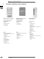

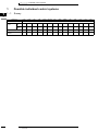
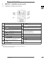
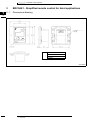
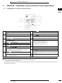

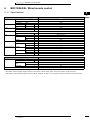
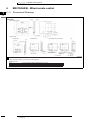
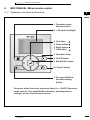
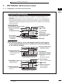
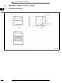
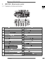

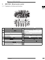


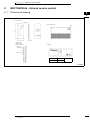


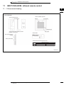


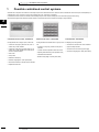

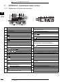
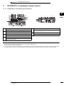
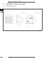
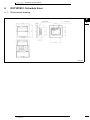
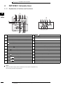
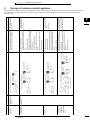
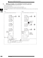
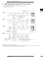
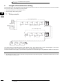
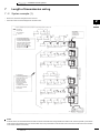
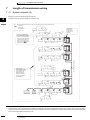

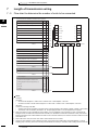

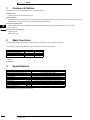
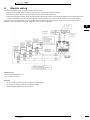


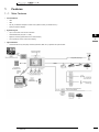
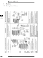


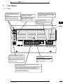
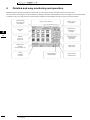
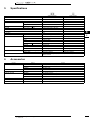
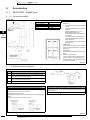
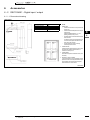

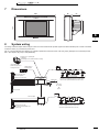
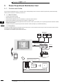


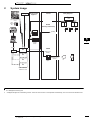

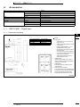

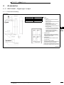
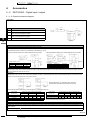

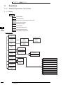

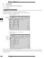
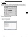
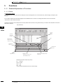
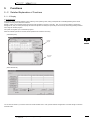


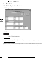
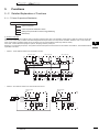

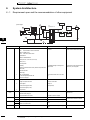

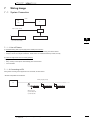
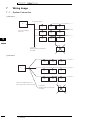
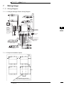
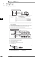

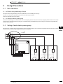
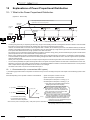
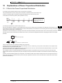
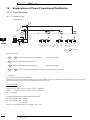
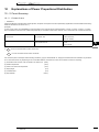
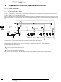


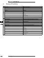


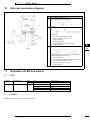

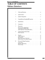
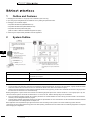
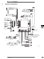
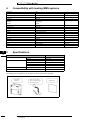
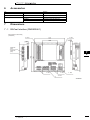
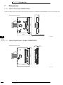
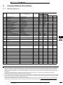

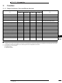


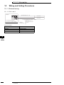


![Capitolato di gara [file ]](http://vs1.manualzilla.com/store/data/006110771_1-d2e80131dc42c63fd97368fc2ee33515-150x150.png)