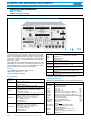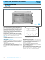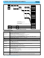
1
DIGITAL LINK
MEASURING
INSTRUMENTS
Pulse Pattern Generators . . . . . . . . . . . . . . . 130, 133
Error Detectors . . . . . . . . . . . . . . . . . . . . . . . 131, 136
10 GHz Jitter Analyzer . . . . . . . . . . . . . . . . . . . . . . 138
Digital Data Analyzers . . . . . . . . . . . . . . . . . . 141, 146
SONET/SDH/PDH/ATM Analyzers . . . . . . . . 150, 169
Portable 2.5G/10G Analyzer . . . . . . . . . . . . . . . . . 172
Data Quality Analyzer . . . . . . . . . . . . . . . . . . . . . . 176
ATM Quality Analyzer . . . . . . . . . . . . . . . . . . . . . . 182
PCM Channel Analyzer . . . . . . . . . . . . . . . . . . . . . 188
Digital Transmission Analyzer . . . . . . . . . . . . . . . . 194
STM/SONET Analyzer . . . . . . . . . . . . . . . . . . . . . . 194
PCM CODEC Analyzer . . . . . . . . . . . . . . . . . . . . . 194
129
DIGITAL LINK MEASURING INSTRUMENTS
PULSE PATTERN GENERATOR
MP1758A
100 MHz to 12.5 GHz (4 channels)
For Evaluating Versatile Transmission Systems, Modules and Devices
GPIB
The MP1758A has a 4-channel data output and a 2-channel clock
output. It can generate two patterns: programmable and pseudorandom. The programmable pattern can be up to 128 K bit long for
each channel. In addition, seven pseudo-random patterns with periods from 2 7 – 1 to 2 31 – 1 can be generated with a 1/4 phase difference for each channel.
The amplitude and offset voltage of the data/clock output can be set
independently for each channel. The setting ranges are 0.5 to 2.0
Vp-p for amplitude, –2.0 to +2.0 VOH for offset voltage, and –500 to
+500 ps for delay between the data and clock outputs.
Features
• Four independently adjustable output channels
• PRBS pattern with max. 231 – 1 bits
• Built-in synthesized clock signal
Specifications
Operation
frequency
0.1 to 12.5 GHz (internal or external clock)
External clock
Input level: 0.8 to 2.0 Vp-p
Input waveform: sine wave (≥500 MHz) or square wave
Connector: APC-3.5
Internal clock
Frequency setting resolution: 1 kHz, 1 MHz
Reference signal: 10 MHz (internal/external, selectable)
Pattern
Pseudo-random pattern: 2n–1 (n = 7, 9, 11, 15, 20, 23, 31)
Programmable pattern: max. 128 Kbit x 4 channels
Logic inversion: provided
Error addition (error rate): 10–n (n = 4, 5, 6, 7, 8, 9), single
Data output
Output waveform: NRZ
Number of outputs: 4 (CH 1, CH 2, CH 3, CH 4)
Amplitude: 0.5 to 2.0 Vp-p (10 mV steps)∗1
Offset voltage: –2.0 to +2.0 VOH (5 mV steps)∗1
ECL termination: provided
Load impedance: 50 Ω
Connector: APC-3.5
Clock output
Number of outputs: 2 (CLOCK 1, CLOCK 2)
Amplitude: 0.5 to 2.0 Vp-p (10 mV steps)∗1
Offset voltage: –2.0 to +2.0 VOH (5 mV steps)∗1
Delay: –500 to +500 ps (1 ps steps)
ECL termination: provided
Load impedance: 50 Ω
Connector: APC-3.5
Sync.
output
Control
Dimensions
and mass
Operating
temperature
EMC
LVD
For product ordering information, see pages 4 – 10
426 (W) x 221 (H) x 450 (D) mm, ≤37 kg
15˚ to 35˚C
EN61326: 1997/A1: 1998 (Class A), EN61000-3-2: 1995/A2:
1998 (Class A), EN61326: 1997/A1: 1998 (Annex A)
EN610101-1:
1993/A2, 1995 (Installation Category ΙΙ, Pollution degree 2)
∗1: Each channel independently
∗2: MS-DOS is a registered trademark of Microsoft Corporation.
Ordering information
Please specify model/order number, name, and quantity when ordering.
Model/Order No.
MP1758A
Name
Main frame
Pulse Pattern Generator
Z0168
W0926AE
W0927AE
Z0306A
Standard accessories
Fuse, 10 A:
2 pcs
Power cord, 2.5 m:
1 pc
GPIB cable, 2 m:
1 pc
Conversion connector (APC3.5-J · APC3.5-J):
7 pcs
Measurement coaxial cable (SMA-P · SMA-P), 0.5 m: 6 pcs
Measurement coaxial cable (SMA-P · SMA-P), 0.8 m: 1 pc
Measurement coaxial cable (HRM202B-3D2W-HRM202B),
1.0 m (for sync. output):
1 pc
3.5-inch floppy disk (2HD):
2 pcs
MP1758A operation manual:
1 copy
MP1758A GPIB operation manual:
1 copy
Wrist strap:
1 pc
MP1758A-01
MP1758A-02
Options
CLOCK/CLOCK output (factory option)
Cross point adjustment (factory option)
F0079
J0008
J0496
J0696A
J0696B
J0693A
J0500A
MB24B
J0007
130
Number of outputs: 1 (1/32 CLOCK OUTPUT/PATTERN
SYNC. OUTPUT, selectable)
Amplitude: 0/–1 V
Load impedance: 50 Ω
Connector: SMA
Control interface: GPIB, parallel
Parameter memory: 3.5-inch FD (MS-DOS∗2 compatible)
Optional accessories
Semi-rigid cable (SMA-P · SMA-P), 0.5 m
Portable Test Rack
(rating current of power cord and plug: 20 A)
GPIB cable, 1 m
DIGITAL LINK MEASURING INSTRUMENTS
ERROR DETECTOR
MP1776A
100 MHz to 12.5 GHz
2
Supports Measurement for up to 50 Gbit/s System (Installed with 4 Channels)
MP1776A is an error detector housing four error detectors that can
measure error up to 12.5 Gbit/s. It has four-channels independent
measurement mode, two-channels or four-channels combined measurement mode and be used for development, manufacturing and
maintenance of transmission systems and modules from 12.5 Gbit/s
to maximum 50 Gbit/s.
Specifications
• MP1776A (main frame), MU177601B (12.5 Gbit/s Error Detector)
NEW
Features
• Max. 4-channels in one box
• Independent measurement of 4-channels
• PRBS patterns from 27 – 1 to 231 – 1
• Max. 32 Mbit programmable pattern at 4-channels combined mode
(corresponding six frames of STM-256/ STS-768)
• Burst data BER measurement for optical circulating loop test
• Good operability by GUI
• Display 4-channels measurement results on screen
Operating frequency
100 MHz to 12.5 GHz
Measurement pattern
PRBS pattern: 2n – 1 (n: 7, 9, 11, 15, 20, 23, 31)
Zero substitution pattern: 2n (n: 7, 9, 11, 15), consecutive zero-pattern can be inserted up to pattern length – 1
Programmable data
Independent: 2 to 8,388,608 bits
2-channels combined: 4 to 16,777,216 bits
4-channels combined: 8 to 33,554,432 bits
Logic inversion: Positive/negative switching possible
Measurement mode
Independent∗1, 2-channels combined∗2, 4-channels combined∗3
Synchronization method
Normal, frame
Error detection mode
Insertion, omission, total
Measurement items
Error ratio: 0.0000 x 10⁻¹⁶ to 1.0000 x 100
Error count: 0 to 9,999,999, 1.0000 x 10⁷ to 9.9999 x 10¹⁶
Clock frequency:
0.1 to 12.5 GHz (independent), 0.2 to 25 GHz (2-channels combined), 0.4 to 50 GHz (4-channels combined)
∗Resolution: 1 kHz, accuracy: 10 ppm ±1 kHz
Sync threshold value
Internal, 10–n (n: 2, 3, 4, 5, 6, 7, 8)
Auto search function
Supported
Data input
Input waveform: NRZ
Input amplitude: 0.5 to 2.0 Vp-p
Threshold voltage: –3.000 to +1.750 V (1 mV step)
Termination condition: GND/–2.0 V
Input impedance: 50 Ω
Connector: APC-3.5
Number of input: 1 (MU177601B 12.5 Gbit/s Error Detector Unit)
Clock input
Input level: 0.5 to 2.0 Vp-p
Input waveform: Square wave only (<0.5 GHz, Duty: 50%), Sine or square wave (≥0.5 GHz, duty: 50%)
Clock delay: ±500 ps (1 ps step)
Polarity inversion: POS/NEG inversion selectable
Input impedance: 50 Ω
Connector: APC-3.5
Number of input: 1 (MU177601B 12.5 Gbit/s Error Detector Unit, up to 4 channel can be added.)
Continued on next page
http://www.anritsu.com
131
DIGITAL LINK MEASURING INSTRUMENTS
Resync input
Input level: 0/–1 V ±0.1 V, Connector: SMA
System environment
Display: 10.4-inch, color LCD, touch screen, 640 x 480 dots, 256 colors (16 M colors in VGA when external display is connected.)
Printer: Parallel port for external printer (D-sub 25-pin)
Keyboard: 101-type (English), PS/2 (mini DIN 6-pin)
Mouse: Serial, PS/2 (mini DIN 6pin)
FDD: 3.5-inch, 2 models (740 KB, 1.44 MB)
HDD
C drive: ≥474 MB (Used for system: measurement data, pattern)
D drive: ≥30 MB (Not accessible to users, interface: IDE)
Remote control
RS-232C (standard, D-sub 9-pin), GPIB (IEEE488.2)
Power
90 to 120 Vac/180 to 250 Vac, 47.5 to 63 Hz, ≤1000 VA
Operating temperature
+15˚ to +35 ˚C
Dimensions and mass
426 (W) x 266 (H) x 584 (D) mm, ≤50 kg (with 4 units of MU177601B)
EMC
EN61326: 1997/A1, 1998 (Class A)
EN61000-3-2: 1995/A2, 1998 (Class A)
EN61326: 1997/A1, 1998 (Annex A)
LVD
EN610101-1: 1993/A2, 1995 (Installation Category ΙΙ, Pollution degree 2)
∗1: Different measurement pattern and frequency can be set for each channel.
∗2: Evaluates 1:2 DEMUX to check that the signal before demultiplexing is PRBS.
∗3: Evaluates 1:4 DEMUX to check that the signal before demultiplexing is PRBS.
Ordering information
Please specify model/order number, name, and quantity when ordering.
Model/order No.
Name
MP1776A
Main frame
Error Detector
J0491
J0670A
F0074
Z0319A
Z0320
W1410AE
W1411AE
Z0306A
Z0352
Z0396A
Standard accessories
Power cord (with shield, 13 A):
1 pc
Power cord (L-type, C7, for 200 V main), 2.5 m: 1 pc
Fuse, 10 A:
1 pc
PS/2 mouse:
1 pc
Input pen:
1 pc
MP1776A operation manual:
1 copy
MP1776A remote operation manual:
1 copy
List strap:
1 pc
MP1776A recovery tool:
2 pcs
Pen holder:
1 pc
MU177601B
Unit
12.5 Gb/s Error Detector Unit
J0696B
J0693A
Standard accessories
Coaxial cable (SMA-P · SMA-P), 0.5 m:
2 pcs
Coaxial cable (HRM202B · 3D2W · HRM202B), 1 m: 1 pc
Z0321A
J0008
B0496
B0374G
B0497A
B0497B
Z0416
Optional accessories
Keyboard (PS/2)
GPIB cable, 2 m
Portable test rack
Carrying case
Dummy unit (for Slot 5)
Dummy unit (for Slot 1 to Slot 4)
Head cleaning disk (for 3.5-inch FDD)
132
For product ordering information, see pages 4 – 10
DIGITAL LINK MEASURING INSTRUMENTS
PULSE PATTERN GENERATOR
MP1763C
12.5 GHz
2
For R&D of High-Speed Logic, ICs, Optical Modules and Devices
GPIB
The MP1763C is used in combination with the MP1764C Error Detector.
The amplitude of the clock and data signals can be varied from 0.25
to 2 Vp-p while the offset can be adjusted to within ±2 V so that the
amplitude and the offset margin can be measured. The clock has a
variable delay function so that time-dependent characteristics or
phase margins of the input clock and data can be measured. An M
series pseudorandom pattern representative of actual conditions or
a programmable pattern can be selected as cell data.
In addition, a 3.5 inch floppy disk drive is built in for storing preset data,
enabling rapid measurements to be performed by simply pressing a
key. A GPIB function is provided, enabling automatic or remote measurement via an external controller.
The MP1763C is a pulse pattern generator ideal for research and development of high-speed logic, ICs, and digital systems.
Operation frequency
64/STS-192
• Generates PRBS patterns with bit length from 27 – 1 to 231 – 1
bits
• Complementary outputs of both data and clock
• The amplitudes and offsets of all 8 data outputs that have 1/8
0.05 to 12.5 GHz
Frequency range
0.05 to 12.5 GHz
SSB phase noise (at 10 kHz
offset, 1 Hz bandwidth)
≤–85 dBc/Hz (0.05 to 4 GHz), ≤–80 dBc/Hz (4 to 8 GHz), ≤–75 dBc/Hz (8 to 10 GHz),
≤–70 dBc/Hz (10 to 12.5 GHz)
External clock input level
Pattern
Features
• High quality waveform
• Low FM/PM-noise clock generator
• 8 Mbit programmable pattern corresponding to six frames of STM-
speed of fundamental clock signal can be set
Specifications
• MP1763C (main frame)
Internal
clock
(option 01)
MX176400A Q and Eye Analysis Software controls MP1763C and
MP1764C from the PC to measure Q factor, eye margin, and eye diagram. MX176401A SDH/SONET Pattern Editor controls the MP1763C
and MP1764C to generate frame pattern conforming to SDH/SONET
standards.
0.4 to 2.5 Vp-p
Pseudorandom binary
sequence pattern (PRBS)
Pattern: 2n – 1 (n: 7, 9, 11, 15, 20, 23, 31)
Mark ratio: 1/2, 1/4, 1/8, 0/8 (1/2, 3/4, 7/8, 8/8 are possible with logic inversion)
Bit shifts number for mark ratio varied: 1, 3 bits selectable
Data pattern
Data length: 2 to 8388608 bits
Alternate pattern
A/B pattern data length: 128 to 4194304 bits (128 bit steps); Loop time: A, B pattern (1 to 127, 1 steps)
Zero substitution pattern
Zero bit length: 1 to (pattern length – 1) bits; Pattern: 2n (n: 7, 9, 11, 15)
Error addition
Error rate: 10–n (n: 4, 5, 6, 7, 8, 9), and single error
External error injection: Provided
Continued on next page
http://www.anritsu.com
133
DIGITAL LINK MEASURING INSTRUMENTS
Data
output
Clock
output
Number of outputs
2 (DATA/DATA independently)
Amplitude
0.25 to 2 Vp-p, 2 mV steps
Offset voltage
VOH: –2 to +2 V, 1 mV steps
Display: VOH, VTH or VOL selectable
Rise/fall time
Typical 30 ps (10% to 90% of amplitude)
Pattern jitter
≤20 psp-p, typical 10 psp-p
Waveform distortion (0-peak)
≤15% or ≤150 mV whichever is greater
Gating input
Provided
Load impedance
50 Ω (with back termination)
Connector
APC-3.5
DATA/DATA tracking
DATA amplitude and offset voltage can be set to the same values as for DATA.
Cross point adjustment function
The cross point of DATA and DATA outputs can be adjusted at semifixed resistor of side.
Number of outputs
3 (CLOCK 1/CLOCK 1, CLOCK 2)
Amplitude
CLOCK 1/CLOCK 1: 0.25 to 2 Vp-p (2 mV steps)
CLOCK 2: 1 Vp-p
Offset voltage
CLOCK 1/CLOCK 1: VOH –2 to +2 V (1 mV steps)
CLOCK 2: VOH 0 V fixed
Rise/fall time
Typical 30 ps (10% to 90% of amplitude)
Load impedance
50 Ω (CLOCK 1/CLOCK 1: with back termination)
Connector
CLOCK 1/CLOCK 1: APC-3.5, CLOCK 2: SMA
Delay
±500 ps (1 ps steps)
1/8 data and clock output
1/4 data
and clock
output (option 03)∗1
Sync. signal
output
Number of outputs: DATA 8, CLOCK 1
Output level: ECL
Connector: SMA
Number of outputs
DATA: 4, CLOCK: 1
Amplitude
0.5 to 2 Vp-p (2 mV steps)
Offset voltage
VOH: –1.5 to +1.5 V (1 mV steps)
Connector
SMA
Number of outputs
1 (1/64 clock, fixed position pattern, or variable position pattern selectable)
Output level
0/–1 V
Connector
Parameter memory
SMA
Media: 3.5 inch FD (2HD, 2DD)
Format: MS-DOS (Rev. 3.1)∗2
Content: Pattern or other parameters
Operating temperature range
0˚ to +50˚C
Dimensions and mass
426 (W) x 221 (H) x 450 (D) mm, ≤33 kg
Power
≤400 VA
EMC
EN61326: 1997/A1, 1998 (Class A)
EN61000-3-2: 1995/A2, 1998 (Class A)
EN61326: 1997/A1, 1998 (Annex A)
LVD
EN610101-1: 1993/A2, 1995 (Installation Category ΙΙ, Pollution degree 2)
∗1: When the Option 03 (1/4 speed output) is added, the 1/8 speed output is not available.
∗2: MS-DOS is a registered trademark of Microsoft Corporation.
• MX176400A Q and Eye Analysis Software
Required
system
Functions
134
Computer: IBM-PC/AT or full compatible, OS: Windows 95/98/NT, CPU: Pentium 166 MHz or higher,
Memory: 64 MB or more, Hard disk space: 100 MB or more
GPIB: National Instruments made GPIB interface (PCMCIA-GPIB or AT-GPIB/TNT series boards are recommended.)
Display
Resolution: 800 x 600 or more, Display colors: 256 or more
∗If two or more applications are running simultaneously, operation cannot be guaranteed.
Measurement frequency: 2 to 12.5 GHz (eye diagram/eye margin measurement), 1 to 12.5 GHz (Q factor measurement)
Measurement patterns: PRGM, PRBS 7, 9, 11, 15, 20, 23, 31
Pattern format: Continuous/burst (To be synchronized within 1 s)
Eye margin measurement
Measurement resolution (threshold): 1 to 10 mV (1 mV steps), Measurement resolution (phase): 1 to 10 ps (1 ps steps),
Measurement rate: E-2 to E-15
Eye diagram measurement
Measurement resolution (phase): 1 to 10 ps (1 ps steps)
Measurement rate: E-2 to E-15 (actual measurement), E-3 to E-12 (estimate measurement)
Display rate: E-2 to E-15 (actual measurement), E-2 to E-4915 (estimate measurement)
Mask test judgment rate: E-2 to E-15
Q factor measurement
Measurement style: Multiple measurements at fixed phase/phase vs. Q factor measurements
Bit error rate range: Upper limit at E-3 to E-5, lower limit at E-7 to E-12
Minimum error count (measurement accuracy): 1, 10, 100, 1000
Vth shift width: Automatic, fixed (1 to 10 mV/1 mV/steps)
For product ordering information, see pages 4 – 10
DIGITAL LINK MEASURING INSTRUMENTS
• MX176401A SDH/SONET Pattern Editor
Required
system
Computer: IBM-PC/AT or full compatible, CPU: Pentium 200 MHz or higher, OS: Windows 95/98/NT, Memory: 64 MB or more
Display
Resolution: 800 x 600 or more; Display colors: 256 or more
FDD: 3.5-inch (1.44 MB), Hard disk space: 100 MB or more
GPIB: National Instruments-made GPIB interface (PCMCIA-GPIB or AT-GPIB/TNT series boards are recommended.)
Functions
SDH/SONET pattern editor
Mapping: STM-N (N = 1, 4c, 12c, 16c, 32c, 64c), STS-N SPE (N = 1, 3c, 12c, 48c, 192c)
Pattern edit: Arbitrary editing of program patterns (PRBS pattern can be inserted in the payload.), time indication, table indication/edit
Payload: Free format, ALL 0, ALL 1, PRBS 2n – 1 (n = 7, 9, 11, 15, 20, 20z, 23, 31) ∗Pattern repetition up to the length of all frames
Measurement condition: ALL, payload, SOH ALL, POH ALL, OH (D1-D3), OH (D4-D12), OH (1 byte) ∗Pattern repetition up to the length of all frames
CID pattern: Available
Frame repetition: Maximum 6 frames
Alarm addition: Alarm addition conforming to SDH/SONET Standard; [items: OOF/LOF, MS-AIS (L-AIS), MS-RDI (L-RDI), MS-REI (L-REI),
HP-AIS (P-AIS), HP-REI (P-REI), HP-RDI (P-RDI)]
BIP error addition: Generates parity errors of B1, B2, and B3
B1, B2, and B3 calculation: Available
Scramble: Available
BIP correction: Available
Bit window: Active for patterns without frame
Block window: Active for patterns without frame with a pattern length of multiples of 32
OH editor: Available
2
Windows is a registered trademark of Microsoft Corporation of the U.S. in the United States and other countries. IBM and AT are registered trademarks of
International Business Machines. Pentium is a registered trademark of Intel Corporation. PCMCIA-GPIB and AT-GPIB/TNT are registered trademarks of National
Instruments.
Ordering information
Please specify model/order number, name, and quantity when ordering.
Model/Order No.
MP1763C
Name
Main frame
Pulse Pattern Generator
Z0168
Z0306A
F0014
W1848AE
W1849AE
Z0481
B0021
Standard accessories
Semi-rigid cable (SMA-P · SX-36 · SMA-P), 0.5 m:
Semi-rigid cable, 7 cm:
Semi-rigid cable, 10 cm:
SMA cable (HRM202B · 3D2W · HRM202B), 1 m:
APC-3.5 J-J connector:
GPIB cable, 2 m:
Power cord:
3.5 inch floppy disk (MF2HD-3.5MF):
Wrist strap:
Fuse, 6.3 A (T6.3A250V):
MP1763C operation manual:
MP1763C GPIB operation manual:
12.5G/3.2G BERTS application software demo:
Protective cover (for 1MW · 5U):
MP1763C-01
MP1763C-03
Options
12.5 GHz synthesizer (50 MHz to 12.5 GHz)
1/4 speed output
68347B
Application equipment
Synthesized Sweep Generator (10 MHz to 20 GHz)
MX176400A
MX176401A
Application software
Q and Eye Analysis Software
SDH/SONET Pattern Editor
J0500A
J0672D
J0672F
J0693A
J0496
J0008
J0500B
J0322A
J0322B
J0007
Z0054
MB24B
B0413A
B0163
B0044
Z0292A
Z0416
2
1
1
1
4
1
1
2
1
1
1
1
1
1
pcs
pc
pc
pc
pcs
pc
pc
pcs
pc
pc
copy
copy
pc
pc
Optional accessories
Semi-rigid cable (SMA-P · SX-36 · SMA-P), 1 m
Coaxial cable (11SMA · SUCOFLEX104 · 11SMA), 0.5 m
Coaxial cable (11SMA · SUCOFLEX104 · 11SMA), 1 m
GPIB cable, 1 m
3.5 inch floppy disk (MF2DD-3.5MF)
Portable Test Rack
(rating current of power cord and plug: 20 A)
Carrying case
Soft carrying case
Rack mount (for 1MW · 5U panel)
Stacking rack (for sweep synthesizer)
3.5 inch head cleaning disk
http://www.anritsu.com
135
DIGITAL LINK MEASURING INSTRUMENTS
ERROR DETECTOR
MP1764C
12.5 GHz
For R&D of High-Speed Logic, ICS, Optical Modules and Devices
GPIB
The MP1764C is used in combination with the MP1763C Pulse Pattern
Generator to detect errors used to evaluate conformity with ITU-T
standards. In addition, complicated searching for input thresholds or
phase adjustments is simplified with the touch of a single key. These
functions are ideally suited for the research and development of ultrahigh-speed logic ICs and digital communication systems.
MX176400A Q and Eye Analysis Software controls MP1764C and
MP1763C from the PC to measure Q factor, eye margin, and eye diagram. MX176401A SDH/SONET Pattern Editor controls the MP1764C
and MP1763C to generate frame pattern conforming to SDH/SONET
standards.
Features
• Auto-search function for setting optimum values of input threshold
and phase setting by a “one-touch” operation
• Synchronization of 8 Mbits pattern is easily made within a short period of time (when in frame mode)
• Errors are detected in intervals as short as 0.1 sec.
• Zero wait time counter gate
Specifications
Operation frequency
Input waveform
Data input
Clock
input
Input amplitude
0.25 to 2.0 Vp-p
Threshold voltage variable range
–3.000 to +1.875 Vp-p (1 mV steps)
Phase margin
≥70 ps (typical value at 10 Gb/s, PRBS 223 – 1, and an input amplitude of 1 Vp-p)
Input sensitivity
50 mVp-p (typical value at 10 Gb/s and PRBS 223 – 1
Termination
Connected to GND or –2 V via a 50 Ω termination
Connector
APC-3.5
Input waveform
Rectangular wave (<0.5 GHz), rectangular or sine wave (≥0.5 GHz), duty factor: 50%
Input voltage
0.25 to 2.0 Vp-p
Input delay variable range
±500 ps (1 ps steps)
Polarity inversion
CLOCK/CLOCK inversion possible
Termination
Connected to GND or –2 V via a 50 Ω termination
Connector
APC-3.5
Auto search function
Pseudorandom binary
sequence pattern (PRBS)
Receive
pattern
0.05 to 12.5 GHz
NRZ
Provided
Pattern: 2n – 1 (n: 7, 9, 11, 15, 20, 23, 31)
Mark ratio: 1/2, 1/4, 1/8, 0/8 (1/2, 3/4, 7/8, 8/8 are possible with logic inversion.)
Number of AND bit shift at mark ratio setting: 1, 3 bits (selectable by using DIP switch on rear panel)
Data pattern
Data length: 2 to 8388608 bits
Alternate pattern
A/B pattern word length: 128 to 4194304 bits (128 bits steps), Number of loops: Controlled using external signal
Zero substitution pattern
Zero bit length: 1 to (pattern length –1) bits, Pattern length: 2n (n: 7, 9, 11, 15)
Continued on next page
136
For product ordering information, see pages 4 – 10
DIGITAL LINK MEASURING INSTRUMENTS
Synchronous mode
Normal, frame, quick
Synchronous threshold
Preset value or 10–n (n: 2, 3, 4, 5, 6, 7, 8)
Error detection mode
Omission insertion, total (selectable with DIP switch on rear panel)
Measurement item
Error rate
0.0000 x 10⁻¹⁶ to 1.0000 x 10–0
Number of errors
0 to 9.9999 x 10¹⁶
Error interval (asynchronous)
0 to 9999999 (interval: 1 ms, 10 ms, 100 ms, 1 s)
Error free interval (EFI)
0.0000% to 100.0000%
Clock frequency
0.05 to 12.5 GHz, (resolution: 1 kHz, accuracy: 10 ppm ±1 kHz)
Eye margin measurement function
Provided
Error performance data calculation function
Provided
2
Measurement CH mask
1 to 32 ch (settable independently)
Block window
Error for any block of 32-bit segments can be measured.
Error analysis (option 01)
Auxiliary
output
Auxiliary
input
Sync. signal
output
Pattern (256 bits in total) before and after bit in which error occurred is stored.
Error output (direct)
1/128 OR error, Output level: 0/–1 V, Connector: SMA
Error output (stretched)
Pulse width: 350 ns (typical), Output level: TTL, Connector: BNC
Alarm output (clock loss,
sync. loss)
Output level: TTL
Connector: BNC
Sync. gain output
Output level: 0/–1 V; Connector: SMA
External mask input
Input level: 0/–1 V; Connector: SMA
Resync. input
Input level: 0/–1 V; Connector: SMA
Alternate A/B switching input
Input level: ECL; Connector: SMA
Number of outputs
1 (1/32 clock, fixed position pattern, or variable position pattern selectable)
Output level
0/–1 V
Connector
Parameter memory
SMA
Media: 3.5 inch FD (2HD, 2DD)
Format: MS-DOS (Rev. 3.1)∗1
Content: Pattern or other parameters
Operating temperature range
0˚ to +50˚C
Dimensions and mass
426 (W) x 221.5 (H) x 450 (D) mm, ≤30 kg
Power
≤300 VA
EMC
EN61326: 1997/A1, 1998 (Class A)
EN61000-3-2: 1995/A2, 1998 (Class A)
EN61326: 1997/A1, 1998 (Annex A)
LVD
EN610101-1: 1993/A2, 1995 (Installation Category ΙΙ, Pollution degree 2)
∗1: MS-DOS is a registered trade mark of Microsoft Corporation.
Ordering information
Please specify model/order number, name, and quantity when ordering.
Model/Order No.
MP1764C
Name
Z0168
F0014
W1846AE
W1847AE
B0306A
B0021
B0481
Standard accessories
Semi-rigid cable (SMA-P · SX-36 · SMA-P), 0.5 m:
SMA cable (HRM202B-3D2W-HRM202B), 1 m:
APC-3.5 J-J connector:
GPIB cable, 2 m:
Power cord:
3.5 inch floppy disk (MF2HD-3.5MF):
Fuse, 6.3 A (T6.3A250V):
MP1764C operation manual:
MP1764C GPIB operation manual:
Wrist strap:
Protective cover (for 1MW · 5U):
12.5G/3.2G BERTS application software demo:
MP1764C-01
Option
Error analysis
J0500A
J0693A
J0496
J0008
Model/Order No.
Main frame
Error Detector
MX176400A
MX176401A
2
3
2
2
1
2
1
1
1
1
1
1
pcs
pcs
pcs
pc
pc
pcs
pc
copy
copy
pc
pc
pc
J0500B
J0322A
J0322B
J0007
Z0054
MB24B
B0413A
B0163
B0044
Z0416
Name
Application software
Q/Eye Analysis Software
SDH/SONET Pattern Editor
Optional accessories
Semi-rigid cable (SMA-P · SX-36 · SMA-P), 1 m
Coaxial cable (11SMA · SUCOFLEX104 · 11SMA), 0.5 m
Coaxial cable (11SMA · SUCOFLEX104 · 11SMA), 1 m
GPIB cable, 1 m
3.5 inch floppy disk (MF2DD-3.5MF)
Portable Test Rack
(rating current of power cord and plug: 20A)
Carrying case
Soft carrying case
Rack mount (for 1MW · 5U panel)
3.5 inch head cleaning disk
http://www.anritsu.com
137
DIGITAL LINK MEASURING INSTRUMENTS
10 GHz JITTER ANALYZER
MP1777A
STM-16 to 64, OC-48 to 192
For Evaluating STM-64/OC-192 Jitter
GPIB
The MP1777A is a measurement solution for jitter evaluation. It supports both the STM-16/32/64 and OC-48/96/192 bit rates. In addition
to supporting the bit rates of 2488.32, 4976.64, and 9953.28 MHz
two additional bit rates used in submarine cable systems can be
added as options.
The MP1777A can evaluate jitter characteristics, including jitter tolerance, jitter transfer, and output jitter, which are parameters most
commonly used to evaluate digital lines.
The MX177701A Jitter Performance Test Software (bundled with
MP1777A) allows the MP1777A to be controlled remotely. When the
Jitter Performance Test Software is used together with specified auxiliary measuring instruments, jitter tolerance and jitter transfer characteristics can be measured automatically.
Functions
• Conforms to 0.172 new recommendations
The MP1777A meets the STM-64/OC-192 measurement standards.
It is compatible with bandwidths up to 80 MHz and jitter modulation
amplitudes up to 3200 UIp-p.
• Four optional series of bit rates
Current submarine cable systems add FEC (forward error correction)
to signals to enhance quality. The MP1777A can also support two
series of bit rates by adding Option 01 (2494.16, 4988.32, 9976.64
MHz), Option 02 (2666.0571, 5332.1142, 10664.2284 MHz), Option
04 (3062.2629, 6124.7259, 12249.4517 MHz) and Option 05
(3069,6138,12276 MHz).
• Automatic jitter measurement
The MX177701A Jitter Performance Test Software is used for automatic jitter measurement and can be used with the MP1777A to configure an automatic measurement system for jitter tolerance and jitter transfer characteristics∗1.
∗1: Requires MS4630B Network Analyzer, MP1763C Pulse Pattern Generator
and MP1764C Error Detector for automatic measurement of jitter tolerance. Requires MS4630B Network Analyzer and MP1763C Pulse Pattern
Generator for automatic measurement of jitter transfer. Also requires
controller, MX177701A Jitter Performance Test Software, GPIB card, and
cables.
138
For product ordering information, see pages 4 – 10
Application examples
• Jitter Generation
To generate jitter, an external signal generator is required to source a
modulation signal. The MX177701A Jitter Performance Test Software
and a GPIB card are required for automatic measurement. It is also
possible to perform manual measurements, which does not require
these items.
• Jitter measurement
The MP1777A can measure the jitter of input signals directly without
using an external BPF. When Option 10 (High Sensitive Input) is installed, it can measure the jitter of input signals with amplitudes
down to 150 mVp-p. In this case, it can perform evaluation by direct
device connection. The MX177701A Jitter Performance Test
Software and a GPIB card are required for automatic measurement.
Manual measurement is also possible and the measurement results
are checked on the MP1777A screen. Furthermore, UIp-p, UI+p, UIp, and UIrms can also be measured.
By combining the MP9677B E/O, O/E converter, the MP1777A can
measure the jitter measurement of optical interfaces.
• Jitter tolerance measurement
By combining the O/E and E/O converters, the MP1777A can
measure the jitter tolerance of optical interfaces. The MX177701A
Jitter Performance Test Software and a GPIB card are required for
automatic measurement. It is also possible to perform manual measurements without these items.
• Measuring Jitter Transfer Characteristics
The MP1777A can evaluate jitter transfer characteristics up to 80
MHz in applications such as 10 Gbit/s clock recovery module (O/E
converter) evaluation. Automatic (using MX177701A external software/GPIB) and manual measurements are possible.
By combining the MP9677B E/O, O/E converter, the MP1777A can
evaluate the jitter transfer characteristics up to 80 MHz at optical interfaces.
DIGITAL LINK MEASURING INSTRUMENTS
Specifications
Bit rate
Standard: 2488.32, 4976.64, 9953.28 Mbit/s
Option 01: 2494.16, 4988.32, 9976.64 Mbit/s
Option 02: 2666.0571, 5332.1143, 10664.2286 Mbit/s
Option 04: 3062.3629, 6124.7259, 12249.4517 Mbit/s
Option 05: 3069,6138,12276 Mbit/s
∗The Option 02 and 04 cannot be mounted at the same time.
2
Modulation frequency: 10 Hz to 80 MHz
Amplitude: 0 to 3200 UIp-p
Resolution: 0.001 UIp-p (0.5 UI range), 0.01 UIp-p (20, 40, 80 UI range), 1 UIp-p (800, 1600, 3200 UI range)
Jitter amplitude (UIp-p)
A3
800/1600/3200 UI range (2488M/4977M/9953M)
–20 dB/dec
A3'
20/40/80 UI range (2488M/4977M/9953M)
A2
–20 dB/dec
A2'
0.5 UI range
A1
f0
Jitter generation
f1 f2
f3 f4'
Jitter frequency (Hz)
f4
f5
Bit rate
(bit/s)
f0
(Hz)
f1
(Hz)
f2
(Hz)
f3
(kHz)
f4
(MHz)
f4’
(kHz)
f5
(MHz)
A1
A2’
A2
A3’
A3
(UIp-p) (UIp-p) (UIp-p) (UIp-p) (UIp-p)
2488M
10
15
480
100
2
100
20
0.5
1
20
25
800
4977M
10
15
480
100
2
100
40
0.5
2
40
50
1600
9953M
10
15
480
100
2
100
80
0.5
4
80
100
3200
Accuracy:
±5% ±10 UIp-p/Fr (3200 UI range), ±5% ±8 UIp-p/Fr (1600 UI range), ±5% ±5 UIp-p/Fr (800 UI range),
±5% ±0.8 UIp-p/Fr (80 UI range), ±5% ±0.6 UIp-p/Fr (40 UI range), ±5% ±0.3 UIp-p/Fr (20 UI range),
±5% ±0.1 UIp-p/Fr (0.5 UI range/10G), ±5% ±0.08 UIp-p/Fr (0.5 UI range/5G), ±5% ±0.05 UIp-p/Fr (0.5 UI range/2.5G)
Fr: 100 kHz (0.5, 20, 40, 80 UI range), 10 Hz (800, 1600, 3200 UI range)
Frequency response error (Fr Hz):
±5% (10 to 20 Hz), ±2% (20 Hz to 300 kHz), ±3% (300 kHz to 1 MHz), ±5% (1 to 3 MHz), ±10% (3 to 10 MHz), ±15% (10 to 80
MHz)
Frequency offset
Auxiliary interface
Range: ±50 ppm (0.1 ppm steps)
Accuracy: ±0.1 ppm (after power-on, calibrates after 60 min. warm-up 23 ±5°C)
External modulation input, external 10 MHz reference input, DCS input, external reference clock input
Jitter amplitude (UIp-p)
Modulation frequency: 100 Hz to 80 MHz
Amplitude: 0 to 4.00 UIp-p, 0 to 1.41 UIrms
Resolution: 0.001 UIp-p/0.001 UIrms (1 UI range), 0.01 UIp-p/0.01 UIrms (4 UI range)
4 UI range
A3
1 UI range
A3'
A2
f0
Jitter measurement
f3
f3
f0
f4 1 UI range
f4 4 UI range
Jitter frequency (Hz)
Bit rate (bit/s)
2488M
4977M
9953M
A2
A3’
A3
(UIp-p) (UIp-p) (UIp-p)
f0
(Hz)
f3
(MHz)
f4
(MHz)
20
1 UI range
0.5
1
—
100
10
4 UI range
0.5
—
4
100
2.5
20
1 UI range
0.5
1
—
100
20
40
4 UI range
0.5
—
4
100
5
40
1 UI range
0.5
1
—
100
40
80
4 UI range
0.5
—
4
100
10
80
Continued on next page
http://www.anritsu.com
139
DIGITAL LINK MEASURING INSTRUMENTS
Accuracy
[UIp-p]: ±5% ±W UIp-p (Fr Hz)
[UIrms]: ±5% ±Y UIrms (Fr Hz), Fr: 100 kHz
Frequency response error (Fr Hz):
±5% (10 to 20 Hz), ±2% (20 Hz to 300 kHz), ±3% (300 kHz to 1 MHz), ±5% (1 to 3 MHz), ±10% (3 to 10 MHz), ±15% (10 to 80
MHz)
W (UIp-p)∗1
Bit rate (bit/s)
Jitter measurement
Auxiliary interface
Y (UIrms)∗2
1 UI
4 UI
1 UI
4 UI
2488M
0.05
0.22
0.008
0.08
4977M
0.07
0.24
0.009
0.09
9953M
0.09
0.26
0.010
0.10
∗1: With HP1 + LP, ∗2: With HP + LP
Filters: LP, HP1 + LP, HP1’ + LP, HP2 + LP, HP + LP, HP' + LP
Bit rate (bit/s)
HP1
(kHz)
HP1’
(kHz)
HP2
(MHz)
HP
(kHz)
HP’
(kHz)
LP
(MHz)
2488M
5
—
1
12
—
20
4977M
8
—
2
12
—
40
9953M
10
20
4
12
50
80
Demodulation output
Internal memory
Measurement conditions: 10
Others
GPIB, Buzzer, Time
Dimensions and mass
426 (W) x 221.5 (H) x 451 (D) mm, ≤23 kg (with options)
Power
100 to 240 Vac, 47.5 to 63 Hz, ≤350 VA
Temperature
10˚ to 40˚C
EMC
EN61326: 1997/A1, 1998 (Class A)
EN61000-3-2: 1995/A2, 1998 (Class A)
EN61326: 1997/A1, 1998 (Annex A)
LVD
EN610101-1: 1993/A2, 1995 (Installation Category ΙΙ, Pollution degree 2)
• Operation environment
Applicable
instruments
Pulse Pattern Generators: MP1763C (12.5 GHz), MP1570A (SONET/SDH/PDH/ATM Analyzer)
Error Detectors: MP1764C (12.5 GHz), MP1570A (SONET/SDH/PDH/ATM Analyzer)
Network Analyzer: MS4630B (300 MHz, with Option 10)
Recommended
controller
Personal computer: IBM-PC/AT compatible
OS: Windows®95 (English) or Windows®98 (English)
CPU: Pentium (75 MHz or faster)
Memory size: 16 Mbyte min.
HDD free space: ≥300 kbyte for full install
GPIB interface: National Instruments AT-GPIB/TNT (PnP), AT-GPIB/TNT+, PCMCIA-GPIB, or PCMCIA-GPIB+ and Windows® driver
(for Windows®95 or Windows®98)
Swap file size: ≥40 Mbyte guaranteed
Display colors: Set to 256
Number of applications running simultaneously: 1 (unable to run other applications simultaneously)
Windows®95 and Windows®98 are registered trademarks of Microsoft® Corporation.
Ordering information
Please specify model/order number, name, and quality when ordering.
Model/Order No.
Name
MP1777A
Main frame
10 GHz Jitter Analyzer
F0014
B0329D
W1497AE
W1498AE
J0496
J0900E
J0776C
J0008
MX177701A
W1499AE
Standard accessories
AC power cord:
Fuse, 6.3 A:
Front cover:
MP1777A operation manual:
MP1777A remote control operation manual:
APC 3.5 J-J connector:
SMA cable (50 Ω), 1.5 m (AA-165-1500):
BNC cable (50 Ω), 1 m:
GPIB cable, 2 m:
Jitter Performance Test Software∗1:
MX177701A operation manual:
Model/Order No.
1
2
1
1
1
2
2
3
1
1
1
pc
pcs
pc
copy
copy
pcs
pcs
pcs
pc
pc
copy
∗1: Please confirm the operating system.
∗2: 2494.16, 4988.32, 9976.64 MHz
∗3: 2666.0571, 5332.1142, 10664.2284 MHz
∗4: 3062.3629, 6124.7259, 12249.4517 MHz
∗5: 3069,6138,12276 MHz
140
For product ordering information, see pages 4 – 10
Name
MP1777A-01
MP1777A-02
MP1777A-04
MP1777A-05
MP1777A-10
Options
2494M/4988M/9977M jitter∗2
2666M/5332M/10664M jitter∗3
3062M/6124M/12249M jitter∗4
3069M/6138M/12276M jitter∗5
High sensitive input (0.15 to 1.3 Vp-p)
MS4630B
MP1763C
MP1764C
MP1570A
MP9677B
Application equipment
Network Analyzer (10 Hz to 300 MHz, with Option 10)
Pulse Pattern Generator (12.5 GHz)
Error Detector (12.5 GHz)
SONET/SDH/PDH/ATM Analyzer
E/O, O/E Converter
DIGITAL LINK MEASURING INSTRUMENTS
DIGITAL DATA ANALYZER
MP1630B
10 kHz to 200 MHz
2
For R&D and Manufacturing of Digital Devices and Equipment
GPIB
OPTION
The MP1630B is a general-purpose bit error measuring instrument
that can provide simultaneous measurements of multi-channel signals and burst signal measurements up to 200 MHz.
The MP1630B is not only for continuous signals – it can measure
burst-signal bit error rates as well. Consequently, it is easily able to
handle burst signals used by TDMA (Time Domain Multiplex Access)
methods and packet/cell transmissions, etc. Both a pulse pattern
generator unit and an error detector unit can be installed in the
MP1630B to measure simultaneously parallel data for 16 channels
using just one unit.
• Mixed pattern generation, selective BER measurement
With the MP1630B, a test pattern can be selected and set for each
channel. Not only can both PRGM and PRBS patterns be used, but
a mixed pattern composed of both PRGM and PRBS patterns can be
generated, too. The packet type and cell type data can be configured
smoothly from the overhead and payload parts. Moreover, the pattern field can split in two to 32 blocks, and a PRGM or PRBS pattern
can be allocated to each column individually. As a result, it is possible to create pseudo-test signals for SDH/ATM, etc., as well as signals for evaluating complex communication protocols.
Features
• 16 channel PPG and ED in one cabinet
• Eye diagram measurement based on BER
Applications
• Testing multi-channel modules for optical interconnection
• E/O, O/E evaluation for optical networks (PON/PDS)
• Testing SDH/ATM equipment and modules
• Testing cable modems for digital CATV
• R&D on TDMA
• R&D on wireless LAN peripherals
• Evaluating next-generation PC interfaces (fiber channel, IEEE 1394,
SSA, ATM-25)
• Evaluating digital demodulators including QPSK/QAM, etc.
• Evaluating IrDA communications equipment
• Evaluating communications LSIs, ASICs/FPGAs, and CCDs, etc.
Performance and functions
• Simultaneous bit error measurement of 16 channels
The MP1630B has 16-channel Pulse Pattern Generator and Error
Detector units and can measure bit errors in parallel and simultaneously. Using the MP1630B shortens the time required to measure
each device to 1/N, thereby greatly improving production efficiency.
• For both continuous and burst data
Continuous data is used in the PDH/SDH transmission system; burst
data is used in the PON (Passive Optical Network) subscriber TDMA
transmission system, as well as in the burst cell unit ATM-PON transmission system. The MP1630B can handle bit error measurement of
both continuous and burst data. It can output burst data for up to 16
channels, and the burst cycle, guard time, preamble length, and data
length can all be varied.
32 block mixed pattern setting screen
• Superior basic functions
A high-performance frequency synthesizer is built into the MP1630B.
It generates stable, accurate signals with high resolution in the 10
kHz to 200 MHz band. In addition, when the optional digital modulator function is used, the jitter tolerance of communications equipment
and devices can also be measured.
In addition to TTL, LVTTL, ECL, and PECL, the pulse pattern generator clock and data output levels can be set to any output (0.25 to 2.5
V at 50 Ω termination; 0.5 to 5.0 V at high) for a variety of interfaces.
The data and clock output delay can be varied at high resolution for
each channel, and there is no need to adjust the cable length for
each signal.
http://www.anritsu.com
141
DIGITAL LINK MEASURING INSTRUMENTS
• One-key/one-parameter operation using customized screens
Measurement of general multi-channel data requires complex operations to manage the large number of measurement parameters. To
make measurement settings simpler, the MP1630B has convenient
customized screens based on the one-key/one parameter operation
used previously in the Anritsu BERTS. It also has a Grouping function which groups together the same measurement items used for
each channel. Common settings (all or pattern-only) are saved as
files on the large internal hard disk.
Pulse pattern generator clock interface screen
Customized screen
• Powerful pattern editor function
10 MHz (V: 800 mV/div, H: 2 ns/div)
Clock delay: –5 to +5 ns/1 ns steps (averaged waveform)
Variable delay characteristics
• Evaluating error correction function using burst error insertion
In addition to having the earlier cyclic and single error-mode insertion functions, the MP1630B has burst-mode insertion functions,
making it ideal for evaluating the efficiency of error-correction codes
used by each type of communication protocol. In particular, it is especially effective for testing digital transmission methods used by
broadcast satellites and mobile phones, etc.
• Evaluating data waveform quality using eye margin measurement
The MP1630B eye margin measurement function can automatically
measure the threshold voltage and phase range below the specified
error rate. It has two measurement modes: the Margin mode and the
Diagram mode. These modes can be selected according to the application.
The MP1630B pulse pattern generator and error detector PRGM
patterns can be edited easily using the keyboard, mouse, or cursor
keys. There are three editing modes matching the various applications: Time, State, and Dump. The Time mode puts time on the horizontal axis and displays the pattern for each channel as a horizontal line. The State mode displays the data of channel 1 as the MSB
and parallel 16 bits (corrected 1 bit from each channel at a time) as
one data item. The Dump mode displays the pattern for the specified
channel as a memory dump image using either binary or hexadecimal code.
Pattern editor (time mode, input waveform)
Margin mode
Diagram mode
142
For product ordering information, see pages 4 – 10
DIGITAL LINK MEASURING INSTRUMENTS
Specifications
Clock
Internal
Operating frequency: 10 kHz to 200 MHz (accuracy: ±2 ppm)
Resolution: 1 kHz steps (>1 to 200 MHz), 100 Hz steps (10 kHz to 1 MHz)
External
Input frequency range: 10 kHz to 200 MHz
Input level: AC, 0.5 to 2.0 Vp-p (50 Ω), BNC connector
External (at locked)
Input frequency range: 10 MHz ±100 ppm, 64 kHz ±100 ppm
Input level: AC, 0.5 to 2.0 Vp-p (50 Ω), BNC connector
2
External modulation input
Modulation frequency range: 10 Hz to 1.3 MHz
Input level range (sine wave): –1 to +1 V (75 Ω), BNC connector
Reference output (jitter-free output): AC, 1 Vp-p (50 Ω), SMA
Jitter: 0 to 50.5 UIp-p (clock frequency: >100 to 200 MHz) ∗Switchable to 50 UI/2 UI range
STM-1 (example)
Jitter modulation function
(option)
Jitter amplitude
[UIp-p]
50.5
50
50 UI range
2 UI range
2.02
2
0.404
0.2
0.01
0.1 0.5
2.6 6.5
65
260
1300 [kHz]
Modulation frequency
Test pattern (pulse pattern
generator, error detector)
PRBS Pattern: 2n – 1 (n: 7, 9, 11, 15, 20, 23, 31), variable mark ratio, logic selectable
Zero substitution pattern: 2n (n: 7, 9, 11, 15); pattern length: n to 2n – 1, logic selectable
PRGM pattern: 2 to 65,536 bits/channel bit length, logic selectable
Mixed pattern: Mixed PRGM and PRBS pattern, logic selectable
∗Block numbers: 2 to 32 [PRGM bit length/block: 8 to 8,912 bits; PRBS bit length/block: 8 to 131,072 bits
(depend on block numbers)]
PON pattern [TDMA test patterns with preamble inserted in ahead of Mixed patterns (PRGM and PRBS)]
Preamble (1010...): 0 to 64 bits; guard time: –2,097,083 to 2,097,067 bits (1 bit resolution)
Burst mode: Internal (burst cycle: 0.1 to 10 ms), external (enable length: 8 to 2,097,144 bits)
Pattern edit function
Edit mode: Dump, timing diagram, state table
Edit results storage: Internal HDD or FDD
Error insertion
Each channel, simultaneous or independently
Error type: Normal, burst
Normal mode (internal: cyclic or single, external)
Error rate: 10–n (n: 3 to 9)
Insert area: Entire area, selected blocks (in Mixed pattern or PON pattern)
Burst mode (internal/external)
Error rate: 10–n (n: 2 to 9)
Internal enable length: 20 to 140 ms (resolution: 20 ms)
Internal cycle: 1 to 10 s (resolution: 1 s)
External mode: Error of specified rate inserted in external signal enable period
Data/clock output
Output No.: 16 (multipin connector), output on/off and logic selectable
Output waveform: NRZ (data), RZ (clock)
Output level: ECL, PECL, TTL, LVTTL, VAR
VAR range
Amplitude: 0.5 to 5 V (10 mV steps, high impedance), 0.25 to 2.5 V (5 mV steps, 50 Ω)
Offset: –4.5 to + 5 V (5 mV steps, high impedance), –2.25 to + 2.5 V (2.5 mV steps, 50 Ω)
Rise/fall times (typ.): 1.3 ns (1 Vp-p, 50 Ω termination)
Clock delay: –5 to +5 ns (100 ps steps)
Data skew: –5 to +5 ns (100 ps steps)
Data/clock input
Input No.: 16, logic selectable, multipin connector
Input waveform: NRZ (data), RZ (clock)
Input level: ECL, PECL, TTL, LVTTL, VAR
VAR input range
Amplitude: 0.5 to 5 V (50 Ω)
Threshold level: –5 to + 5 V (5 mV steps, in 50 Ω to GND termination)
Clock delay: –5 to +5 ns (100 ps steps)
Measurement data
Channel No.: 16 channels simultaneous measurement (selectable measurement channels)
Signal format: Continuous or burst (internal/external)
Bit error measurement
Alarm measurement
Error detection: All, insertion, omission
Measurement region: All, PRGM, PRBS selectable, and each block selectable with block configuration
Display
Error rate: 0 x 10–16 to 1.0000 x 100
Error count: 0 to 9999999, 1.0000 x 10⁷ to 9.9999 x 10¹⁶
Error interval: 0 to 9999999, 1.0000 x 10⁷ to 9.9999 x 10¹⁶
Error free interval: 0.0000 to 100.0000%
Error performance: ITU-T Rec. G.821
Measurement mode: Single, repeat, untimed (1 second to 99 days 23 hours 59 minutes 59 seconds)
Auto sync: ON/OFF switchable [threshold value: 1 x 10–n (n: 2 to 8)], with autosearch function
Detected items: Power loss, clock loss, pattern sync loss (PRGM, PRBS)
Continued on next page
http://www.anritsu.com
143
DIGITAL LINK MEASURING INSTRUMENTS
Frequency measurement
Measurement range: 10 kHz to 200 MHz
Effective digits: 6 digits
Resolution: 100 Hz
Accuracy: ± (1 count ±10 ppm)
Eye margin measurement
(based on BER)
Measures eye margin or eye diagram of specified data (1 channel)
Eye margin: Displays threshold margin and phase margin as numeric values
Eye diagram: Displays width of eye aperture as two-dimensional graph using bit-error measurement
Delay measurement
Mode: Single/repeat
Unit: Time/bit numbers
Range
Time: 0 to 999 µs (1 µs steps), 1 to 999 ms (1 ms steps), 1 to 10 s (1 s steps)
Bits: 231 bits (max.)
Time out: 0.5, 1, 2, 5, 10 s
I/O signal for
burst BER
measurement
Pulse
pattern
generator
External burst input
Level: TTL (H: Enable, L: Disable), BNC connector
Burst trigger output (index signal for each burst data)
Output No.: 16 (for each data output), bit delay function
Level: ECL, –2 V (50 Ω), multipin connector
Auxiliary output (PON system envelope, or AGC reset signal; usable as normal control signal)
Output No.: 8 (selectable channel), 1 (OR output for each channel), bit delay function, logic selectable
Level: ECL or TTL (≤100 Mb/s), multipin connector
Error
detector
Burst trigger input
Input No.: 16 (for each data input)
Level: ECL, –2 V (50 Ω), multipin connector
Other I/O signals
Sync signal output (pulse pattern generator, error detector)
Sync source: 1/1 clock, 1/8 clock, PRGM pattern, PRBS pattern
Level: 0/–1 V (50 Ω), BNC connector
External error input (pulse pattern generator)
Error mode: Normal, burst
Level: TTL, BNC connector
Trigger output (pulse pattern generator)
Trigger source: Unique pattern index for delay measurement or pattern block index in MIX/PON pattern
Level: 0/–1 V (50 Ω), multipin connector
Trigger input (error detector)
Trigger source: For delay measurement
Level: 0/–1 V (50 Ω), multipin connector
System environment
Platform: Microsoft Windows operating system version 3.1
Display: Color LCD, touch screen, 640 x 480 dots, 256 colors
Printer: Parallel port for printer, D-sub 25-pin connector
Keyboard: 101 keys (English), PS2 mini-DIN 6-pin connector
Mouse: Serial, PS2 mini-DIN 6-pin connector
FDD: 2 mode (1.44 MB, 740 KB)
HDD
C drive: ≥1,380 MB (for measurement data, patterns)
D drive: 30 MB (not released to user, interface: IDE)
Remote control
RS-232C (standard), GPIB (option): IEEE488.2, Ethernet (option): 10 Base-T
Other functions
Sound: When error or alarm detected, panel lock function, self check function
Power
100 to 120/200 to 240 Vac, 47.5 to 63 Hz, ≤1,000 VA
Dimensions and mass
426 (W) x 221.5 (H) x 451 (D) mm, ≤29 kg
Operating temperature
5˚ to 40˚C
The specifications are with the MU163000A (200M Clock Generator Unit), MU163020B (200M 16CH Pulse Pattern Generator Unit), and MU163040B (200M 16CH
Error Detector Unit) installed in the MP1630B main frame.
144
For product ordering information, see pages 4 – 10
DIGITAL LINK MEASURING INSTRUMENTS
Ordering information
Please specify model/order number, name, and quantity when ordering.
Model/Order No.
MP1630B
Name
Main frame
Digital Data Analyzer
Z0396A
W1442AE
W1443AE
W1450AE
Standard accessories
Power cord (shielded):
Fuse, 10 A:
PS/2 mouse:
Input pen:
MP1630B recovery disk (only for MP1630B
customer):
MP1630B application disk (only for MP1630B
customer):
MP1630B remote sample disk (only for
MP1630B customer):
Pen holder:
MP1630B operation manual:
MP1630B remote control operation manual:
MP1630B auto adjust operation manual:
MP1630B-01∗1
MP1630B-02∗1
Options
GPIB (GPIB interface board)
Ethernet (Ethernet interface board)
Z0321A
J0008
MB24B
B0348
B0329D
B0333D
Peripherals
Keyboard (PS/2)
GPIB cable
Portable Test Rack (specified current: 10 A)
Soft case
Front cover
Rack mount kit
MU163000A∗1
Plug-in unit
200M Clock Generator Unit
W1187AE
Standard accessories
MU163000A operation manual:
J0491
F0087
Z0319A
Z0320
Z0388
Z0389
Z0390
1
2
1
1
pc
pcs
pc
pc
Model/Order No.
Name
MU163040B∗1, ∗ 2
Plug-in unit
200M 16CH Error Detector Unit
J0828
J0829
J0693D
W1444AE
11 pc
7 pc
J0776D
1
1
1
1
1
pc
pc
copy
copy
copy
J0824
J0825
J0826
J0827
J0858
J0859
J0860
J0861
Standard accessories
Multi-core cable, (16 pins), 0.5 m:
2
Multi-core cable, (17 pins), 0.5 m:
1
SMA cable, 0.27 m:
1
MU163020B/163040B operation manual
(not supplied when Pulse Pattern Generator Unit
purchased at same time):
1
2
pcs
pc
pc
copy
Peripherals
Coaxial cord (BNC-P-3W · 3D-2W · BNC-P-3W), 2 m
(double shield)
BNC multi-core cable (16 pins), 1 m
BNC multi-core cable (9 pins), 1 m
SMA multi-core cable (16 pins), 1 m
SMA multi-core cable (9 pins), 1 m
SMA multi-core cable (16 pins), 2 m
SMA multi-core cable (9 pins), 2 m
BNC multi-core cable (16 pins), 2 m
BNC multi-core cable (9 pins), 2 m
∗1: Factory option
∗2: Requires multi-core cable shown in peripherals (sold separately) for measurements
Microsoft is a registered trademark of Microsoft Corporation.
Microsoft Windows is a registered trademark of Microsoft Corporation.
Windows is an abbreviation for Microsoft Windows Operating System.
Other product names used in this brochure are registered trademarks or products of their respective owners or manufactures.
1 copy
Option
MU163000A-01∗1 Jitter addition
J0776D
Peripherals
Coaxial cord (BNC-P-3W · 3D-2W · BNC-P-3W), 2 m
(double shield)
MU163020B∗1, ∗2
Plug-in unit
200M 16CH Pulse Pattern Generator Unit
J0693B
W1444AE
Standard accessories
SMA cable, 0.27 m:
MU163020B/163040B operation manual:
J0776D
J0824
J0825
J0826
J0827
J0858
J0859
J0860
J0861
2 pcs
1 copy
Peripherals
Coaxial cord (BNC-P-3W · 3D-2W · BNC-P-3W), 2 m
(double shield)
BNC multi-core cable, (16 pins), 1 m
BNC multi-core cable, (9 pins), 1 m
SMA multi-core cable, (16 pins), 1 m
SMA multi-core cable, (9 pins), 1 m
SMA multi-core cable, (16 pins), 2 m
SMA multi-core cable, (9 pins), 2 m
BNC multi-core cable, (16 pins), 2 m
BNC multi-core cable, (9 pins), 2 m
http://www.anritsu.com
145
DIGITAL LINK MEASURING INSTRUMENTS
DIGITAL DATA ANALYZER
MP1632C
50 MHz to 3.2 GHz
For Development, Manufacturing and Inspection of Transmission Systems, Optical Modules and Logic Devices
GPIB
OPTION
Core networks and computer networks are increasing rapidly as the
volume of data transmitted in this multimedia data is growing. In addition to the STM-16/OC-48 (2.488 Gbit/s), Fibre channel, Giga-bit
Ethernet, etc. are being commercialized. Compact and high performance digital data analyzer are required for inspecting products like
digital transmission systems, optical modules, and logic devices.
The MP1632C realizes a compact solution that incorporates former
measuring equipment (MP1652A Pulse Pattern Generator and
MP1653A Error Detector) into a case.
MX163201A TEXT to MP1632A/C Pattern Conversion Software,
MX163202A MP165X to MP1632A/C Pattern Conversion Software,
MX163205A Q and Eye Analysis Software, and MX163206A SDH/
SONET Pattern Editor are available as application software.
Features
• 3.2 Gb/s PPG and ED in a case
• Eye diagram measurement and burst signal measurement supported
Performance and functions
• Easy operation
The MP1632C has a large, color LCD with touch screen. Microsoft
Windows ® operating system version 3.1 displays measurement results graphically. Customized screens enable one-key and one-parameter operation.
• High-quality pulse pattern generator
Programmable patterns of 8 Mbit max, PRBS patterns [(27 – 1) to
(231 – 1) with variable mark ratio], and zero substitution patterns can
be generated. Variable cross-point of data output waveform is also
supported.
146
For product ordering information, see pages 4 – 10
DATA
Clock
H: 100 ps/div, V: 1 V/div
MU163220C output waveform (3.2 GHz)
• Error detector with many functions
High input sensitivity (25 mVp-p∗) and wide phase margin (250 ps∗)
performance is provided. The autosearch function enables PRBS
pattern search with usual phase and threshold search. Insertion error and omission error can be measured simultaneously.
∗Typical values at 3 Gb/s, PRBS 223 – 1
• Internal synthesizer with high signal purity (Option)
Highly pure signals, SSB phase noise characteristics of –85 dBc/Hz
or less (10 kHz offset), is generated.
• Support of various applications
The MP1632C supports testing of SDH/SONET (STM-0, 1, 4, 16/
OC-1, 3, 12, 48) devices and modules, research and development on
WDM components, Fibre channels, Giga-bit Ethernet, evaluation of
E/O and O/E module, GaAs IC, and high-speed ASIC/FPGAs
DIGITAL LINK MEASURING INSTRUMENTS
Specifications
• MU163220C 3.2G Pulse Pattern Generator
Operating frequency
10 MHz to 3.2 GHz (50 MHz to 3.2 GHz when using MP1632C-03 3.2G Internal Synthesizer)
External clock input
0.5 to 2 Vp-p (<0.5 GHz: square wave, ≥0.5 GHz: square wave or sine wave, 50% duty cycle)
Generation pattern
Pseudo random pattern (PRBS)
Pattern length: 2 n – 1 (n: 7, 9, 11, 15, 20, 23, 31)
Mark ratio: 1/2, 1/4, 1/8, 0/8, 1/2, 3/4, 7/8, 8/8
AND bit shift upon mark ratio setting: 1, 3 bits
Data pattern
Data length: 2 to 8,338,608 bits
Zero substitution pattern
Continuous 0 bit length: 1 to (pattern length – 1) bits
Pattern length: 2 n (n: 7, 9, 11, 15)
Error insertion
Error ratio: 10–n (n: 3, 4, 5, 6, 7, 8, 9), single error
External error input: Provided
Data output
Number of outputs: 2 (DATA/DATA, independent)
Amplitude: 0.5 to 2 Vp-p (10 mV steps, setting error: ±15% or ±0.1 V, whichever is greater)
Offset voltage
VOH: –2 to +2 V (at 2 Vp-p amplitude), –3.5 to +2 V (at 0.5 Vp-p amplitude)
(5 mV steps, setting error: ±15% of offset voltage, ±0.1 V or ±15% of amplitude, whichever is the greatest)
Display: VOH, VTH, and VOL selectable
Rise/fall time: ≤80 ps (10% to 90% of amplitude)
Pattern jitter: ≤30 psp-p
Waveform distortion: 10% or 0.1 V of amplitude, whichever is greater
Load impedance: 50 Ω (with back termination)
Connector: SMA
DATA/DATA tracking: DATA amplitude and offset voltage can be set to same value as DATA.
Crosspoint adjustment function: Provided
Clock output
Number of output: 2 (CLOCK/CLOCK, independent)
Amplitude: 0.5 to 2 Vp-p (10 mV steps, setting error: ±15% or ±0.1 V, whichever is greater)
Offset voltage
VOH : –2 to +2 V (at 2 Vp-p amplitude), –3.5 to +2 V (at 0.5 Vp-p amplitude)
(5 mV steps, setting error: ±15% of offset voltage, ±0.1 V or ±15% of amplitude, whichever is the greatest)
Display: VOH, VTH, and VOL selectable
Rise/fall time: ≤80 ps (10% to 90% of amplitude)
Load impedance: 50 Ω (with back termination)
Connector: SMA
Clock delay: –1 to +1 ns (2 ps steps)
External burst trigger input
Input level: 0/–1 V, connector: SMA
Internal burst signal
Burst cycle: 2 µs to 50 ms (1 µs steps), Enable length: 1 µs to 49.999 ms (1 µs steps)
2
Burst trigger output
Output level: 0/–1 V, connector: SMA
Sync signal output
Number of outputs: 1 (1/8 clock, variable pattern synchronization output selectable), Output level: 0/–1 V, Connector: SMA
Operating temperature
+5 to +45˚C
Power
≤200 VA
Dimensions and mass
232 (W) x 49 (H) x 449 (D) mm, ≤4.5 kg
• MU163240C 3.2G Error Detector
Operating frequency
10 MHz to 3.2 GHz (50 MHz to 3.2 GHz when using MP1632C-03 3.2G Internal Synthesizer)
Data input
Input waveform: NRZ
Input voltage: 0.5 to 4 Vp-p
Variable threshold voltage: –4 to +4 V (1 mV steps)
Termination: Connected to GND, –2 V or +3 V via 50 Ω
Connector: SMA
Clock input
Input waveform: Square wave (<0.5 GHz), square wave or sine wave (≥0.5 GHz), duty: 50%
Input amplitude: 0.5 to 4 Vp-p
Variable input delay: –1 to +1 ns (2 ps steps)
Polarity inversion: POS/NEG inversion selectable
Termination: Connected to GND, –2 V or +3 V via 50 Ω
Connector: SMA
Auto search function
Phase, threshold, phase & threshold, PRBS pattern (allowed if the mark ratio is between 1/8 and 7/8)
Receive pattern
Pseudo random pattern (PRBS)
Pattern length: 2 n – 1 (n: 7, 9, 11, 15, 20, 23, 31)
Marker ratio: 1/2, 1/4, 1/8, 0/8, 1/2, 3/4, 7/8, 8/8
AND bit shift upon mark ratio setting: 1, 3 bits
Data pattern
Data length: 2 to 8,338,608 bits
Zero substitution pattern
Continuous 0 bit length: 1 to (pattern length – 1) bits
Pattern length: 2 n (n: 7, 9, 11, 15)
Sync mode
Normal, frame
Sync threshold
AUTO or 10–n (n: 2, 3, 4, 5, 6, 7, 8)
Error detection mode
Omission, insertion, total
Continued on next page
http://www.anritsu.com
147
DIGITAL LINK MEASURING INSTRUMENTS
Measurement items
Error rate: 0.0000 x 10⁻¹⁶ to 1.0000 x 100
Number of errors: 0 to 9.9999 x 10¹⁶
Error interval (async): 0 to 9999999 (Interval: 100 ms, 1 s)
Error free interval (EFI): 0.0000 to 100.0000%
Clock frequency: 0.01 to 3.2 GHz (resolution: 1 Hz, accuracy: 10 ppm ±1 kHz)
Eye margin measurement
function
Provided
Error performance
calculation function
Provided
Measurement channel mask
1 to 8 channels, each channel settable independently
Error output
Number of output: 1 (1/32 bit rate OR error), Output level: 0/–1, Connector: SMA
Sync signal output
Number of outputs: 1 (switchable among 1/8 clock, fixed pattern sync, sync gain output)
Output level: 0/–1 V, Connector: SMA
Burst trigger input
Input level: 0/–1 V, connector: SMA
Operating temperature
+5˚ to +45˚C
Power
≤250 VA
Dimensions and mass
232 (W) x 54 (H) x 449 (D) mm, ≤5 kg
• MP1632C (Main frame)
OS: Microsoft Windows ® operating system Version 3.1
Display: 10.4 inch, color LCD (touch screen), 640 x 480 dots, 256 colors
Printer: Parallel port for external printer (D-sub, 25-pins)
Keyboard: 101 type (English), PS/2 (mini DIN 6-pin connector)
Mouse: Serial, PS/2 (mini DIN, 6-pin connector)
FDD: 2 modes (1.44 MB, 740 KB)
HDD
C drive: ≥474 MB (used for system: measurement data, pattern), D drive: ≥30 MB (not accessible to users, interface: IDE)
System environment
Remote control
RS-232C (standard), GPIB (option): IEEE488.2, Ethernet (option): 10 Base-T
EMC
EN61326: 1997/A1, 1998 (Class A)
EN61000-3-2: 1995/A2, 1998 (Class A)
EN61326: 1997/A1, 1998 (Annex A)
LVD
EN610101-1: 1993/A2, 1995 (Installation Category ΙΙ, Pollution degree 2)
Power supply
100 to 120 Vac/200 to 240 Vac, 47.5 to 63 Hz, ≤150 VA
Operating temperature
+5˚ to +45˚C
Dimensions and mass
426 (W) x 221.5 (H) x 451(D) mm, ≤20 kg
• 3.2G internal synthesizer (Option 03)
Frequency range
50 MHz to 3.2 GHz (1 kHz steps)
Frequency accuracy
±2 ppm
SSB phase noise
≤–85 dBc/Hz (10 kHz offset, 1 kHz bandwidth)
Non-harmonic
spurious
≤–60 dBc (limited to spurious 10 kHz or more
distant from carrier frequency)
Reference lock range
10 MHz ±10 ppm
Power
≤50 VA
Mass
≤5 kg
• Eye diagram template (Option 20)
Required system
MP1632A
Function
Adding templates on the MP1632A’s eye diagram
result screen
• MX163201A TEXT to MP1632A/C Pattern Conversion Software
Required system
Computer: IBM-PC/AT or full compatible, OS: Windows 3.1/95/98, CPU: Pentium 133 MHz or higher, Memory: 32 MB or more,
Hard disk space: 25 MB or more
Display
Resolution: 640 x 480 or more, Display colors: 256 or more
FDD: 3.5-inch (1.44 MB)
Text file
A text file describing the program pattern in hex format (maximum number of characters in a line: 32696 bits including spaces
and return characters)
MP1632A/C pattern data
file (PTN)
All the MP1632A/C set data and patterns (file format for reading/writing on the MP1632A/C main screen)
MP1632A/C pattern clip
file (PCP)
Only patterns (a file format that can be read or written in the MP1632A/C Pattern Editor)
• MX163202A MP165X to MP1632A/C Pattern Conversion Software
Required system
Computer: IBM-PC/AT or full compatible, OS: Windows 3.1/95/98, CPU: Pentium 133 MHz or higher, Memory: 32 MB or more,
Hard disk space: 25 MB or more
Display
Resolution: 640 x 480 or more, Display colors: 256 or more
FDD: 3.5-inch (1.2/1.44 MB)
Input file
MP165X program pattern files: MP165X’s reading/writing and edit
File name: T∗∗.PTN (for pulse pattern generator ), R∗∗.PTN (for error detector)
Output file
MP1632A/C pattern data file (PTN):
All the MP1632A/C set data and patterns (file format for reading/writing on the MP1632A/C main screen)
MP1632A/C pattern clip file (PCP): Only patterns (File format that can be read or written in the MP1632A/C’s pattern editor.)
Note: Since the FD format of MP165X is 1.2 MB, the PC must read 1.2 MB format FD.
148
For product ordering information, see pages 4 – 10
DIGITAL LINK MEASURING INSTRUMENTS
• MX163205A Q and Eye Analysis Software
Required system
Function
Computer: IBM-PC/AT or full compatible, OS: Windows 95/98/NT, CPU: Pentium 166 MHz or higher,
Memory: 64 MB or more, Hard disk space: 100 MB or more,
GPIB: National Instruments made GPIB interface (PCMCIA-GPIB or AT- GPIB/TNT series boards are recommended.)
Display
Resolution: 800 x 600 or more, Display colors: 256 or more
∗If two or more applications are running simultaneously, operation cannot be guaranteed.
2
Measurement frequency: 1 to 3.2 GHz
Measurement patterns: PRGM, PRBS 7, 9, 11, 15, 20, 23, 31
Pattern format: Continuous/burst (To be synchronized within 1 s)
Eye margin measurement
Measurement resolution (threshold): 1 to 10 mV (1 mV steps), Measurement resolution (phase): 2 to 10 ps (2 ps steps),
Measurement rate: E-2 to E-15
Eye diagram measurement
Measurement resolution (phase): 2 to 10 ps (2 ps steps)
Measurement rate: E-2 to E-15 (actual measurement), E-3 to E-12 (estimate measurement)
Display rate: E-2 to E-15 (actual measurement), E-2 to E-4915 (estimate measurement)
Mask test judgment rate: E-2 to E-15
Q factor measurement
Measurement style: Multiple measurements at fixed phase/phase vs. Q factor measurements
Bit error rate range: Upper limit at E-3 to E-5, lower limit at E-7 to E-12
Minimum error count (measurement accuracy): 1, 10, 100, 1000
Vth shift width: Automatic, fixed (1 to 10 mV/1 mV steps)
• MX163206A SDH/SONET Pattern Editor
Required system
Functions
Computer: IBM-PC/AT or full compatible, CPU: Pentium 200 MHz or higher, OS: Windows 95/98/NT, Memory: 64 MB or more
Display
Resolution: 800 x 600 or more; Display colors: 256 or more
FDD: 3.5-inch (1.44 MB), Hard disk space: 100 MB or more,
GPIB: National Instruments made GPIB interface (PCMCIA-GPIB or AT-GPIB/TNT series boards are recommended.)
SDH/SONET pattern editor
Mapping: STM-N (N = 1, 4c, 12c, 16c), STS-N SPE (N = 1, 3c, 12c, 48c)
Pattern edit: Arbitrary editing of program patterns (PRBS pattern can be inserted in the payload.), time indication, table indication/edit
Payload:
Free format, ALL 0, ALL 1, PRBS 2n – 1 (n = 7, 9, 11, 15, 20, 20z, 23, 31) ∗Pattern repetition up to the length of all frames
CID pattern: Available
Frame repetition : Maximum 26 frames
Alarm addition:
Alarm addition conforming to SDH/SONET Standard
∗items: OOF/LOF, MS-AIS (L-AIS), MS-RDI (L-RDI), MS-REI (L-REI), HP-AIS (P-AIS), HP-REI (P-REI), HP-RDI (P-RDI)
BIP error addition: Generates parity errors of B1, B2, and B3
B1, B2, and B3 calculation: Available
Scramble: Available
BIP correction: Available
OH editor: Available
Windows is a registered trademark of Microsoft Corporation of the U.S. in the United States and other countries. IBM and AT are registered trademarks of
International Business Machines. Pentium is a registered trademark of Intel Corporation. PCMCIA-GPIB and AT-GPIB/TNT are registered trademarks of National
Instruments.
Ordering information
Please specify model/order number, name, and quantity when ordering.
Model/Order No.
Name
Model/Order No.
MP1632C
Main frame
Digital Data Analyzer
F0090
Z0319A
Z0320
Z0347
Z0393
Z0395
Z0396A
W1859AE
W1860AE
B0447B
Standard accessories
Power cord (shielded):
Fuse, 8 A:
PS/2 mouse:
Input pen:
Recovery disk∗1:
Application disk∗1:
Remote sample disk∗1:
Pen holder:
MP1632C operation manual:
MP1632C remote control operation manual:
Dummy unit for EXTENSION:
MP1632C-01
MP1632C-02
MP1632C-03
Options
GPIB
Ethernet
3.2G internal synthesizer
MX163201A
MX163202A
MX163205A
MX163206A
Application software
TEXT to MP1632A/C Pattern Conversion Software
MP165X to MP1632A/C Pattern Conversion Software
Q and Eye Analysis Software
SDH/SONET Pattern Editor
1
2
1
1
1
1
1
1
1
1
1
pc
pcs
pc
pc
set
set
set
pc
copy
copy
pc
∗1: Only for MP1632C customer
∗2: Units are factory options (not user replaceable)
∗3: Not supplied when 3.2G pulse pattern generator purchased as same time
Z0321A
J0008
B0447A
B0447C
B0447D
Z0416
MB24B
B0348
B0329D
B0333D
J0905A
Z0398
W1529AE
Name
Peripherals
Keyboard (PS/2)
GPIB cable, 2 m
Dummy unit for CG
Dummy unit for PPG
Dummy unit for ED
3.5 inch head cleaning disk
Portable Test Rack (specified current: 20 A)
Soft case
Front cover
Rack mount kit
Semi-rigid cable (for Option 03)
Ethernet installation disk (for Option 02)
Ethernet operation manual (for Option 02)
MU163220C
3.2G Pulse Pattern Generator∗2
J0693A
J0696A
W1857AE
Z0306A
Standard accessories
Coaxial cord (HRM202B · 3D2W · HRM202B), 1 m:
Coaxial cord (AA-165-500), 0.5 m:
MU163220C/163240C operation manual:
Wrist strap:
MU163240C
3.2G Error Detector∗2
J0693A
J0696A
W1857AE
Standard accessories
Coaxial cord (HRM202B · 3D2W · HRM202B), 1 m: 1 pc
Coaxial cord (AA-165-500), 0.5 m:
2 pcs
MU163220C/163240C operation manual∗3:
1 copy
http://www.anritsu.com
1
2
1
1
pc
pcs
copy
pc
149
DIGITAL LINK MEASURING INSTRUMENTS
SONET/SDH/PDH/ATM ANALYZER
MP1570A
1.5 Mbit/s to 10 Gbit/s
Comprehensive Testing of Core Networks from One Compact Portable Analyzer
GPIB
OPTION
The MP1570A analyzer is designed for development, manufacturing,
construction, maintenance, and inspection of SDH, SONET, PDH,
and ATM equipment and networks.
A variety of plug-in units and options are available that offer the flexibility to the users to configure various analysis systems for different
applications.
The MP1570A is scalable from 1.5 Mbit/s to 10 Gbit/s, and has six
slots to install the plug-in units required for SDH, SONET and PDH
tests at bit different rates. Installing the appropriate combinations of
plug-in units can also perform ATM, jitter and wander tests conform
to ITU-T O.171/O.172.
The MP1570A conforms to the ITU-T recommendations and Bellcore
standards, and supports concatenation mapping, tandem connection, APS measurement, CID measurement and POS measurement.
The user can measure 1.5 Mbit/s to 10 Gbit/s signals using a single
MP1570A; previously, this required several measuring instruments.
The MP1570A has a built-in printer and a 3.5-inch floppy disk drive
as standard output devices to print measurement results, and to
save and read measurement data to and from the floppy disk (FD),
which can also be read on an external PC. The user can also save
screen data to the FD. The MP1570A has a "HELP" key function that
explains operations, functions and connections.
SDH, SONET and PDH measurement
• Measurement at bit rates from 1.5 Mbit/s to 10 Gbit/s
Mapping
• Overhead setting and testing
The user can modify and capture the overhead, and test the overhead portion with overhead change, pointer 64 frames, overhead
add/drop and overhead bit errors.
• APS function
The user can test the automatic protection switch (APS) by measuring the equipment switching time accurately in milliseconds. The
MP1570A also conforms to ITU-T Rec. G.783 and G.841.
A mapping route to a bit rate of up to 10 Gbit/s can be set.
The MP1570A mainly supports SDH, SONET, and Japanese mapping, European PDH and North American DSn for digital communications. For concatenation mapping, a route can be set from STM1c/STS-3c up to STM-64c/STS-192c. Furthermore, the MP1570A
supports a combination of channels. For example, 64 channels of
VC4c/STS3c, 16 channels of VC4-4c/STS-12c, and four channels of
VC4-16c/STS-48c (See Figure 1 or Figure 2 in page 154 or 155).
APS test sub-screen
• Mixed payload
At mapping measurement in TUG-3 and AU3, the user can set different mapping for three additional channels other than the target
measurement channel.
150
For product ordering information, see pages 4 – 10
DIGITAL LINK MEASURING INSTRUMENTS
• Tandem connection
• Wander measurement (option)
The N1/Z5 and N2/Z6 bytes can be set and measured.
• Various analysis functions
The internal optical power meter and frequency counter allows the
user to measure optical power and frequency during error and alarm
measurement without changing the connections of the signal cables.
The MP1570A can capture any SOH/TOH or POH (1 byte), K1/ K2
byte, or H1/H2 byte in 1023 frames to analyze errors and alarms, and
check APS operation.
Measured errors and alarms can be displayed as a graph with a time
scale in 1 second, 1 minute, 15 minutes, or 60 minutes.
• Pointer value monitoring
Changes in pointer value can be displayed as a graph with values
updated in real time.
• MUX/DEMUX function (option)
When the MUX/DEMUX option is added, the multiplexing structure
including the frame alignment signal can be generated, and multiplexer/demultiplexer measurement can be performed.
• Non frame pattern/CID pattern
Frames can be set on/off at all bit rates. CID pattern can generate or
analysis at SONET/SDH measurements.
• Through modes
One of the three through modes can be selected: (1) Transparent, (2)
Overhead/Overwrite, and (3) Payload/Overwrite. The external
DS1/DS3/PDH signal can be added/dropped to/from payload at payload overwrite.
• Enhanced error/alarm simulation
The MP1570A can generate normal and abnormal frames alternately to test the frame synchronization function of terminal equipment.
(This is an SDH/SONET FAS error addition function.)
• Easily operated pointer sequence test (combined jitter measurement)
Able to generate the justification pattern conforming to ITU-T G.783
from the transmission equipment side, and simultaneously make the
tributary signal offset variable. This makes the combined jitter test
possible.
Subdivides the bandwidth of the wander measurement into three
ranges, and can analyze the wander factor caused by temperature
change, pointer, etc. It can also perform measurements conforming
to ITU-T O.172.
• Through jitter function (only SONET/SDH)
Able to generate the jitter by through, while monitoring the input jitter
quality.
Jitter, wander measurements (1.5 Mbit/s to 2.5 Gbit/s)
The jitter/wander measurement conforming to ITU-T O.171/O.172
exceeds these standards in performance evaluation. Automatic measurements, such as jitter tolerance, jitter transfer, and jitter vs. frequency offset are performed in a short time. Various automatic measurements can be achieved with just one unit.
ATM
• Supports ATM from 1.5M to 622M rates
TC layer mappings of 622M, 156M, 52M, 139M, 45M, 34M, 2M and
1.5M are supported along with ATM mappings of O.191, AAL1,
AAL2, AAL3/4, and AAL5, which makes the MP1570A ideal for various combinations of layers. The VPI/VCI for 1023 channels can be
detected automatically, and the presence/absence of alarms, cell
count, and non-conforming cell count can be displayed graphically,
for easy comparison of line channel traffic.
• 1- and 2-point CDV in conformance with I.356
When measuring delay in cell traffic, either 1-point CDV or 2-point
CDV conforming to ITU-T Rec. I.356 can be selected according to
the conditions.
• Simultaneous display of error cells, inserted error cells and
lost cells
The error/alarm generation conditions can be displayed both numerically and graphically to give a visual impression of the traffic conditions.
• Traffic monitoring
The constantly changing traffic can be displayed as a graph for the
selected-one-channel VPI/VCI.
IP-over-SONET/SDH, IP-over-ATM (option)
Programs IP/PPP at will transmits it, picks PPP packet from capture
memory (option), displays it and supports high-speed POS router
evaluation. And programs IP in the AAL5 payload at will transmits it,
picks the IP packet from the cell capture memory, and displays it.
And supports ATM router evaluation.
• IP/PPP header setting
Able to set the value of each header optionally when selecting IPv4
or IPv6. Calculates FCS or header checksum automatically.
• Various wander generation functions (option)
Various wander generations for evaluation are available: such as
TDEV wander tolerance measurement and TDEV wander transfer
characteristics measurement that were regulated by ITU-T, ANSI,
Bellcore, and ETSI.
• PPP packet transmission and real time count
Transmits the three types of packets (can be set separately) by optional sequence (the idle length between each packet can be set simultaneously.). Displays the number of Tx packets and Rx ppp packets at real time.
• PPP packet capture and display
Samples PPP packet from the capture memory, and displays IP
header. Detects FCS error and displays it in red.
http://www.anritsu.com
151
2
DIGITAL LINK MEASURING INSTRUMENTS
Specifications
• MP0121A 2/8/34/139/156M*1 Unit
Bit rate
2.048, 8.448, 34.368, 139.264 Mbit/s
Level/waveform
Conforms to ITU-T G.703 (with 20 dB monitoring point)
Connectors
BNC (75 Ω, unbalanced), 3-pin Siemens (120 Ω, balanced)
2.048 Mbit/s: HDB3 (balanced/unbalanced)
8.448, 34.368 Mbit/s: HDB3 (unbalanced)
139.264 Mbit/s: CMI (unbalanced)
Clock
Internal (accuracy: ±7 ppm, jitter unit not installed), external (ECL [AC] 50 Ω), received signal
Frame format
Unframed: 2, 8, 34, 139 Mbit/s
Framed: 2 Mbit/s (with/without CRC-4 at channels 30/31, G.704), 8 Mbit/s (G.742), 34 Mbit/s (G.751), 139 Mbit/s (G.751),
MUX/DEMUX (Option 06)
Test patterns
PRBS: 211 – 1, 215 – 1, 220 – 1, 223 – 1 (O.151)
Invert: On/off
Word: 16-bit programmable, all 0, all 1
Error addition
Bit (all, test pattern), code, E-bit
Timing: Single, rate (1E–3, 1E–4, 1E–5, 1E–6, 1E–7)
FAS: n in 16 (n: 1 to 4), all
Alarm addition
LOS, LOF, AIS, RDI, RDI (MF)
Timing: All
Measurements
Mode: Single, repeat, manual
In-service
Errors: Frame, code, CRC-4, E-bit
Alarms: Power-fail, LOS, AIS, LOF, MF loss, RDI, RDI (MF)
Error performance: G.821 (inc. Annex D), M.2100, G.826
Out-of-service
Errors: Frame, code, CRC-4, E-bit, bit
Alarms: Power-fail, LOS, AIS, LOF, MF loss, RDI, RDI (MF), sync loss
Error performance: G.821 (inc. Annex D), M.2100, G.826
LEDs
LOS, AIS, LOF, MF loss, RDI, RDI (MF), sync loss, errors
Monitor
Frame word
Trouble search
Auto search for errors/alarms in all measured channels
Delay measurement
0 to 1 s
Auxiliary interface
Clock sync output, frame sync output, error output
∗1: Built-in 156M CMI (electrical) interface
• MP0122A 1.5/45/52M*1 Unit, MP0122B 1.5/45/52/52M*2 (1.31) Unit
Bit rate
1.544, 44.736 Mbit/s
Level/waveform
1.544 Mbit/s: ANSI T1.102 (with 20 dB monitoring point), 0/655 ft
44.736 Mbit/s: ANSI T1.102 (with 20 dB monitoring point), 0/450/900 ft
Connectors
BNC (75 Ω, unbalanced), BANTAM (100 Ω, balanced)
1.544 Mbit/s: AMI/B8ZS (balanced), 44.736 Mbit/s: B3ZS (unbalanced)
Clock
Internal (accuracy: ±7 ppm, jitter unit not installed), external (ECL [AC] 50 Ω) received signal
Frame format
Unframed: 1.5, 45 Mbit/s
Framed: 1.5 Mbit/s (D4, ESF, Japan ESF∗3), 45 Mbit/s (M13, C-bit), MUX/DEMUX (Option 07)
Test patterns
PRBS: 211 – 1, 215 – 1, 220 – 1 (zero suppress), 220 – 1, 223 – 1 (O.151)
Invert: On/off
Word: 16-bit program, all 0, all 1, 3 in 24 (1.5 Mbit/s)
Error addition
Bit (all, test pattern), code, parity, CRC-6, C-bit, REI
Timing: Single, rate (1E–3, 1E–4, 1E–5, 1E–6, 1E–7)
FAS (45 Mbit/s): n in 16 (n: 1 to 4), all
X-bit setting
00, 01, 10, 11
Alarm addition
LOS, LOF, AIS, RDI
Timing: All
Measurements
Mode: Single, repeat, manual
In-service
Errors: FAS, code, parity, CRC-6, C-bit, REI
Alarms: Power-fail, LOS, AIS, LOF, RDI
Error performance: G.821 (inc. Annex D), M.2100, G.826
Out-of-service
Errors: FAS, code, parity, CRC-6, C-bit, REI, bit
Alarms: Power-fail, LOS, AIS, LOF, RDI, sync loss
Error performance: G.821 (inc. Annex D), M.2100, G.826
LEDs
LOS, LOF, AIS, RDI, sync loss, errors
Trouble search
Auto search for errors/alarms in all measured channels
Delay measurement
0 to 1 s
Auxiliary interface
Clock sync output, frame sync output, error output
∗1: Built-in 52M B3ZS (electrical) interface
∗2: Built-in 52M B3ZS (electrical) and optical interfaces
∗3: Mounted Option 09 (Japan mapping)
152
For product ordering information, see pages 4 – 10
DIGITAL LINK MEASURING INSTRUMENTS
• 52/156/622/2488/9953M (SDH)
Bit rate
51.84, 155.52, 622.08, 2488.32, 9953.28 Mbit/s
Level/waveform
52M (electrical: B3ZS)∗1: ANSI T1.102, 0/450 ft
52M (optical): As per MP0122B unit optical interface specifications
156M (electrical: CMI)∗2: ITU-T G.703
156M (optical): As per optical 156M/622M unit specifications
622M (electrical/optical): As per optical 156M/622M unit and NRZ unit specifications
2488M (electrical/optical): As per 2.5G unit and 2.5G/10G unit specifications
9953M (electrical/optical): As per 2.5G/10G unit specifications
Clock
Internal (accuracy: ±3.5 ppm, jitter unit not installed), Lock (2 MHz, 1.5 MHz, 64 kHz + 8 kHz, 2 Mbit/s, 1.5 Mbit/s),
external (ECL [AC] 50 Ω, 9953M: 1.02 to 0.58 Vp-p, 50 Ω), received signal
Frame
SDH/SONET, CID pattern, non-frame
Mapping
See Fig. 1
2
Through
Trance parent, over head overwrite, payload overwrite
Test patterns
PRBS: 211 – 1, 215 – 1, 220 – 1 (zero suppress, MP0122A/B installed), 220 – 1, 223 – 1, 231 – 1 (only concatenation mapping
16c/64c, conform to O.151)
Invert: On/off
Word: 16-bit programmable, all 0, all 1
Error addition
Bit all (all, test pattern), FAS, B1, B2, B3, BIP-2, MS-REI, HP-REI, LP-REI
Timing: Single, single (burst) bit (1 to 64000), rate (1E–3, 1E–4, 1E–5, 1E–6, 1E–7, 1E–8, 1E–9)
User program AE-B [A: 1.0 to 9.9 (step: 0.1), B: 2 to 10]
Alternative: Error frame (0 to 8000), normal frame (1 to 8000)
Alarm addition
LOS, LOF, MS-AIS, MS-RDI, AU-AIS, AU-LOP, HP-SLM, HP-TIM, HP-RDI, HP-UNEQ, TU-AIS, TU-LOP, TU-LOM, LP-SLM,
LP-TIM, LP-RDI, LP-UNEQ, LP-RFI
Timing: Single, single (burst) frame
Alternative: Alarm frame (0 to 8000), normal frame (1 to 8000), all
Measurements
Mode: Single, repeat, manual
In-service/Out-of-service
Errors: B1, B2, B3, BIP-2, MS-REI, HP-REI, LP-REI
Alarms: Power-fail, LOS, LOF, OOF, MS-AIS, MS-RDI, AU-AIS, AU-LOP, HP-SLM, HP-TIM, HP-RDI, HP-UNEQ, TU-AIS,
TU-LOP, TU-LOM, LP-SLM, LP-TIM, LP-RDI, LP-UNEQ, LP-RFI
Error performance: G.826, M2101, M2110, M2120
Preset: Alarm measurement condition
LEDs
LOS, LOF, OOF, MS-AIS, MS-RDI, AU-AIS, AU-LOP, HP-RDI, HP-SLM, TU-AIS, TU-LOM, TU-LOP, LP-RDI, LP-RFI, LP-SLM,
Tandem, sync. loss, errors
Tandem connection
N1 byte (Type 1, Type 2), N2 byte
Errors: N2 BIP-2, TC-REI, OEI, IEC
Alarms: VC-AIS, ISF, FAS, HP-Incoming-AIS, HP-TC-RDI, HP-ODI, LP-Incoming-AIS, LP-TC-RDI, LP-ODI
Justification
AU pointer, TU pointer, C, C1/C2
Measurement: NDF, +PJC, –PJC, Cons, C, C1/C2
Monitor
SOH, POH, K1/K2, pointer, path trace (TIM alarms detectable), Tandem, payload
Pointer sequence
Signal of opposites polarity, regular with double, regular with missing, double of opposites polarity, 87-3/26-1 (normal, add, cancel),
continuous pattern (normal, add, cancel), single pointer adjustment, maximum rate pointer burst, phase transient pointer burst,
initialize period polarity, cooldown period
Over head capture
SOH/POH (any 1 byte), H1/H2, K1/K2
Dummy channel setting
Payload: Dummy, copy, mixed payload
Setting: POH, pathtrace, SS bit, Tandem
Simultaneous measurement
VC2, VC12, VC11
Trouble search
Auto search for errors/alarms in all measured channels
Delay
Measurement period: 0.5, 1, 2, 5, 10 s
Measurement range: 0 to 999 µs, 1.0 to 999.9 ms, 1.0 to 10.0 s, time out
Display accuracy: ±5 µs (0.5, 1 s), ±50 µs (2, 5, 10 s)
APS (K1/K2)
Switching time measurement
Measurement range: 1 to 2000 ms, >2000 ms
Trigger
Internal: B1, B2, B3, BIP-2, MS-REI, HP-REI, LP-REI, MS-AIS, AU-AIS, AU-LOP, HP-RDI, TU-AIS, TU-LOM, TU-LOP, LP-RDI,
LP-RFI, Bit
External: Measures trigger input signal (active high)
Threshold: Specify non-error alarm between 1 ms, 10 ms, 100 ms
Sequence generation: 2 to 64 word, repeat (8000 frame)
Sequence capture: 2 to 64 word, repeat (8000 frame)
Frequency measurement
Range: ±100 ppm, Accuracy: ±3.5 ppm (jitter unit not installed)
Over head test
OH change: SOH/POH 1 byte, K1/K2, RSOH, MSOH, SOH, POH (except B1, B2, B3, BIP-2)
PTR 64 frame: AU pointer, TU pointer
Timing: Single, repeat (2 to 64)
Setting: PTR, NDF, +PJC, –PJC
OH BERT: SOH/POH 1 byte (exclude B1, B2, B3, BIP-2), D1-D3, D4-D12
Test pattern: 211 – 1, 215 – 1
OH add/drop: SOH/POH 1 byte, D1-D3, D4-D12 (exclude B1, B2, B3, BIP-2 additional type)
Japan mapping (option 09)
VC11 Signaling (8-multiframe, 64-multiframe setting)
Frame memory/capture
Memory size: 64 frame (156M, 622M, Option 13), 64 frame (MU150008A-01/150009A-01/150010A-01, 2.5G),
26 frame (MU150000A-01, 2.5G/10G)
Insert/extract
Bit rate: 10G (52M, 156M), 2.5G (52M, 156M)
Payload offset
±100 ppm/0.1 ppm step
Auxiliary interface
Clock sync output, trigger input, trigger output, DCC interface (V.11), orderwire, receive clock output
∗1: Mounted MP0122A/B,
∗2: Mounted MP0121A
http://www.anritsu.com
153
DIGITAL LINK MEASURING INSTRUMENTS
STM-64
x 64
STM-16
x 16
x4
AU-4
AUG
139M (Async.)∗1
VC-4
Bulk∗1
x3
STM-4
TUG-3
x3
STM-1
TU-3
VC-3
34M (Sync.)∗1
x7
STM-0
AU-3
34M (Async.)∗1
45M (Async.)∗3
VC-3
Bulk∗3
x7
TU-2
TUG-2
VC-2
Bulk
6M (Async.)
x3
6M (Bit sync.)
mc
TU-12
VC-12
2M (Async.)∗1
2M (Bit sync. F)∗1
2M (Bit sync. L)∗1
2M (Byte sync. F)∗1
x4
2M (Byte sync. L)∗1
Bulk∗1
TU-11
VC-11
1.5M (Async.)
1.5M (Bit sync. F)
1.5M (Bit sync. L)
1.5M (Byte sync. F)
1.5M (Byte sync. L)
∗1: Requires MP0121A
∗2: Requires Japan mapping (Option 09)
∗3: Requires MP0122A/B
∗4: Requires MU150000A
∗5: Requires MU150000A, MU150008A, MU150009A or MU150010A
STM-64c∗4
STM-16c∗4,∗5
x4
STM-4c
x4
x4
STM-1c
Bulk
384k (data)∗2
384k (voice)∗2
Byte (data)∗2
Byte (voice)∗2
VC4-64c
Bulk
VC4-16c
Bulk
VC4-4c
Bulk
VC4c
Bulk
Fig. 1 Mapping structure (SDH)
• 52/156/622/2488/9953M (SONET)
Bit rate
51.84, 155.52, 622.08, 2488.32, 9953.28 Mbit/s
Level/waveform
52M (electrical: B3ZS)∗1: ANSI T1.102, 0/450 ft
52M (optical): As per MP0122B unit optical interface specifications
156M (electrical: CMI)∗2: ITU-T G.703
156M (optical): As per optical 156M/622M unit specifications
622M (electrical/optical): As per optical 156M/622M unit and NRZ unit specifications
2488M (electrical/optical): As per 2.5G unit and 2.5G/10G unit specifications
9953M (electrical/optical): As per 2.5G/10G unit specifications
Clock
Internal (accuracy: ±3.5 ppm, jitter unit not installed), Lock (2 MHz, 1.5 MHz, 64 kHz + 8 kHz, 2 Mbit/s, 1.5 Mbit/s),
External (ECL [AC] 50 Ω, 9953M: 1.02 to 0.58 Vp-p, 50 Ω), received signal
Frame
SDH/SONET, CID pattern, non-frame
Mapping
See Fig. 2
Through
Trance parent, over head overwrite, payload overwrite
Test patterns
PRBS: 211 – 1, 215 – 1, 220 – 1 (zero suppress, MP0122A/B installed), 220 – 1, 223 – 1, 231 – 1 (only concatenation mapping
16c/64c, conform to O.151)
Invert: On/off
Word: 16-bit programmable, all 0, all 1
Error addition
Bit all (all, test pattern), FAS, B1, B2, B3, BIP-2, REI-L, REI-P, REI-V
Timing: Single, single (burst) bit (1 to 64000), rate (1E–3, 1E–4, 1E–5, 1E–6, 1E–7, 1E–8, 1E–9)
User program AE-B [A: 1.0 to 9.9 (step: 0.1), B: 2 to 10]
Alternative: Error frame (0 to 8000), normal frame (1 to 8000)
Alarm addition
LOS, LOF, AIS-L, RDI-L, AIS-P, LOP-P, PLM-P, HP-TIM, RDI-P, UNEQ-P, AIS-V, LOP-V, LOM-V, PLM-V, LP-TIM, RDI-V, UNEQ-V, RFI-V
Timing: Single, single (burst) frame
Alternative: alarm frame (0 to 8000), normal frame (1 to 8000), all
Measurements
Mode: Single, repeat, manual
In-service/Out-of-service
Errors: B1, B2, B3, BIP-2, REI-L, REI-P, REI-V
Alarms: Power-fail, LOS, LOF, OOF, AIS-L, RDI-L, AIS-P, LOP-P, PLM-P, HP-TIM, RDI-P, UNEQ-P, AIS-V, LOP-V, LOM-V,
PLM-V, LP-TIM, RDI-V, UNEQ-V, RFI-V
Error performance: G.826, M2101, M2110, M2120
Preset: Alarm measurement condition
LEDs
LOS, LOF, OOF, AIS-L, RDI-L, AIS-P, LOP-P, RDI-P, PLM-P, AIS-V, LOM-V, LOP-V, RDI-V, RFI-V, PLM-V, Tandem, sync. loss, errors
Tandem connection
Z5 byte (Type 1, Type 2), Z6 byte
Errors: Z6 BIP-2, TC-REI, OEI, IEC
Alarms: VC-AIS, ISF, FAS, HP-Incoming-AIS, HP-TC-RDI, HP-ODI, LP-Incoming-AIS, LP-TC-RDI, LP-ODI
Continued on next page
154
For product ordering information, see pages 4 – 10
DIGITAL LINK MEASURING INSTRUMENTS
STS pointer, VT pointer, C, C1/C2
Measurement: NDF, +PJC, –PJC, Cons, C, C1/C2
Justification
Monitor
TOH, POH, K1/K2, pointer, path trace (TIM alarms detectable), Tandem, payload
Pointer sequence
Signal of opposites polarity, regular with double, regular with missing, double of opposites polarity, 87-3/26-1 (normal, add, cancel),
continuous pattern (normal, add, cancel), single pointer adjustment, maximum rate pointer burst, phase transient pointer burst,
initialize period polarity, cooldown period
Over head capture
TOH/POH (any 1 byte), H1/H2, K1/K2
Dummy channel setting
Payload: Dummy, copy, mixed payload
Setting: POH, pathtrace, SS bit, Tandem
Simultaneous measurement
VT6SPE, VT2SPE, VT1.5SPE
Trouble search
Auto search for errors/alarms in all measured channels
Delay
Measurement period: 0.5, 1, 2, 5, 10 s
Measurement range: 0 to 999 µs, 1.0 to 999.9 ms, 1.0 to 10.0 s, time out
Display accuracy: ±5 µs (0.5, 1 s), ±50 µs (2, 5, 10 s)
APS (K1/K2)
Switching time measurement
Measurement range: 1 to 2000 ms, >2000 ms
Trigger
Internal: B1, B2, B3, BIP-2, REI-L, REI-P, REI-V, AIS-L, AIS-P, LOP-P, RDI-P, AIS-V, LOM-V, LOP-V, RDI-V, RFI-V, Bit
External: Measures trigger input signal (active high)
Threshold: Specify non-error alarm between 1 ms, 10 ms, 100 ms
Sequence generation: 2 to 64 word, repeat (8000 frame)
Sequence capture: 2 to 64 word, repeat (8000 frame)
Frequency measurement
Range: ±100 ppm, Accuracy: ±3.5 ppm (jitter unit not installed)
Over head test
OH change: TOH/POH 1 byte, K1/K2, LOH, SOH, TOH, POH (except B1, B2, B3, BIP-2)
PTR 64 frame: STS pointer, VT pointer
Timing: Single, repeat (2 to 64)
Setting: PTR, NDF, +PJC, –PJC
OH BERT: TOH/POH 1 byte (exclude B1, B2, B3, BIP-2), D1-D3, D4-D12
Test pattern: 211 – 1, 215 – 1
OH add/drop: TOH/POH 1 byte, D1-D3, D4-D12 (exclude B1, B2, B3, BIP-2 additional type)
Japan mapping (option 09)
VT1.5SPE Signaling (8-multiframe, 64-multiframe setting)
Frame memory/capture
Memory size: 64 frame (156M, 622M, Option 13), 64 frame (MU150008A-01/150009A-01/150010A-01, 2.5G),
26 frame (MU150000A-01, 2.5G/10G)
Insert/extract
Bit rate: 10G (52M, 156M, 622M), 2.5G (52M, 156M, 622M)
Payload offset
±100 ppm/0.1 ppm step
Auxiliary interface
Clock sync output, trigger input, trigger output, DCC interface (V.11), orderwire, receive clock output
∗1: Mounted MP0122A/B,
STS-192
∗2: Mounted MP0121A
x 64
STS-48
x 16
x4
STS-12
STS3
139M (Async.)∗1
STS3cSPE
Bulk∗1
x3
TUG-3
x3
STS-3
TU-3
VC-3
STS-1
34M (Async.)∗1
34M (Sync.)∗1
45M (Async.)∗1
x7
STS1SPE
Bulk∗3
x7
VT6
VTG
VT6SPE
Bulk
6M (Async.)
x3
6M (Bit sync.)
mc
VT2
VT2SPE
2M (Async.)∗1
2M (Bit sync. F)∗1
2M (Bit sync. L)∗1
2M (Byte sync. F)∗1
2M (Byte sync. L)∗1
x4
Bulk∗1
VT1.5
VT1.5SPE
1.5M (Async.)
1.5M (Bit sync. F)
1.5M (Bit sync. L)
1.5M (Byte sync. F)
1.5M (Byte sync. L)
∗1: Requires MP0121A
∗2: Requires Japan mapping (Option 09)
∗3: Requires MP0122A/B
∗4: Requires MU150000A
∗5: Requires MU150000A, MU150008A, MU150009A or MU150010A
STS192∗4
STS48∗4,∗5
STS12
STS3
x4
x4
x4
Bulk
384k (data)∗2
384k (voice)∗2
Byte (data)∗2
Byte (voice)∗2
STS192c
Bulk
STS48c
Bulk
STS12c
Bulk
STS3c
Bulk
Fig. 2 Mapping structure (SONET)
http://www.anritsu.com
155
2
DIGITAL LINK MEASURING INSTRUMENTS
• IP-over-SONET/SDH (Option)*1
Bit rate
155.52, 622.08, 2488.32, 9953.28 Mbit/s
PPP setting
(RFC1662)
Flag, address, control: Any settable
Protocol: 8/16 bit selectable and any settable
FCS: 16/32 bit selectable and auto calculate
Information: IPv4/IPv6 selectable and any settable
IPv4 setting
(RFC0791)
Any setting: Version, IHL, TOS, total length, ID, flags, flagment offset, TTL, protocol, address (source, destination)
Header checksum: Auto calculate
Data byte: All 0, all 1, 8 bits program, single PRBS 7, user program (max. 65535 byte)
IPv6 setting
(RFC1883)
Any setting: Version, priority, flow label, payload length, next header, hop limit, address (source, destination)
Data byte: All 0, all 1, 8 bits program, single PRBS 7, user program (max. 65535 byte)
Packet transmission
setting
1 to 3 in IP/PPP (independently), IP/PPP sending pattern, packet sending interval (max. 100000 bytes), single/repeat, sending
on/off, scramble (X43 + 1) on/off, control escape auto insertion, FCS error insertion (single), number of packet count display
Packet
receiving/analysis
PPP frame calculation (count), scramble (X43 + 1) on/off setting, automatic analysis of control escape. Frame/capture memory
(option) required data captured into the capture memory (max. 64 frames∗2), IPv4/IPv6 select, IP address filter set
∗1: The frame/capture memory (option) is required.
∗2: Maximum 26 frames at 2488/9953 Mbits when MU150000A is inserted.
• IP-over-ATM (Option)*1
Bit rate
155.52, 622.08 Mbit/s
AAL5 edit pattern
IPv4/IPv6 selectable
IPv4 setting
(RFC0791)
Any setting: Version, IHL, TOS, total length, ID, flags, flagment offset, TTL, protocol, address (source, destination)
Header checksum: Auto calculate
Data byte: All 0, all 1, 8 bit program, single PRBS 7, user program (max. 65535 bytes)
IPv6 setting
(RFC1883)
Any setting: Version, priority, flow label, payload length, next header, hop limit, address (source, destination)
Data byte: All 0, all 1, 8 bits program, single PRBS 7, user program (max. 65535 bytes)
Packet sending
Follow with AAL5 distribution setting
Packet
receiving/analysis
Displays the IP packet from the data captured into cell capture memory (maximum 2016 cells), IPv4/IPv6 selectable
∗1: MP0123A ATM Unit is required.
• General
Printer
Internal, external
Internal memory
Measurement settings memory: 10, Graphics memory: 15
Others
FDD, RS-232C (Option 01)∗1, GPIB (Option 02)∗1, Ethernet (Option 03)∗1, video output (Option 04)∗1, buzzer, clock, help, screen
copy
EMC
EN61326: 1997/A1, 1998 (Class A)
EN61000-3-2: 1995/A2, 1998 (Class A)
EN61326: 1997/A1, 1998 (Annex A)
LVD
EN610101-1: 1993/A2, 1995 (Installation Category ΙΙ, Pollution degree 2)
Dimensions and mass
320 (W) x 177 (H) x 350 (D) mm, 10 kg approx. (excluding plug-in units and options)
Power
100 to 240 Vac, 47.5 to 63 Hz, ≤500 VA
Temperature
0˚ to +40˚C
∗1: The video output, RS-232C, GPIB and Ethernet options cannot all be used simultaneously.
Only the video output + RS-232C, or video output + GPIB, or RS-232C + GPIB board, or Ethernet board combinations support simultaneous use, so change
the board combinations according to the purpose.
156
For product ordering information, see pages 4 – 10
DIGITAL LINK MEASURING INSTRUMENTS
• MU150005A/150006A/150007A Jitter Units
Bit rate
MU150005A: 2.048, 8.448, 34.368, 139.264, 155.52, 622.08 Mbit/s
MU150006A: 1.544, 44.736, 51.84, 155.52, 622.08 Mbit/s
MU150007A: 1.544, 2.048, 8.448, 34.368, 44.736, 139.264, 51.84, 155.52, 622.08 Mbit/s
Conform to ITU-T O.171/O.172
Modulation frequency: 0.1 Hz to 6 MHz
Amplitude: 0 to 404.0 UIp-p
Resolution:0.001 UIp-p (2 UI range), 0.01 UIp-p (16 UI range), 0.1 UIp-p (80 UI range), 0.2 UIp-p (400 UI range)
[UIp-p]
400 Ul range
2
400 Ul range
80 Ul range
16 Ul range
2 Ul range
400.0
–20 dB/dec
80 Ul range
Jitter modulation
80.8
–20 dB/dec
16 Ul range
16.16
–20 dB/dec
2 Ul range
2.020
–20 dB/dec
0.60
0.50
0.20
f1
Jitter generation
f2
(Hz)
f2
f3
f4
Modulation frequency
f5
f6 f7
Bit rate
(Mbit/s)
f1
(Hz)
1.544
130
630
3.2
25
—
100
—
2.048
300
1.5k
7.5
60
—
240
—
8.448
1.1k
5.5k
28
220
—
880
—
34.368
2.5k
13k
63
500
—
—
5000
5000
(Hz)
f3
f4
f5
f6
f7
(kHz) (kHz) (kHz) (kHz) (kHz)
44.736
2.5k
13k
63
500
—
—
139.264
9k
45k
230
1800
6000
—
—
51.84
2.5k
13k
63
500
—
—
5000
155.52
7.5k
38k
190
1500
—
6000
—
622.08
3k
15k
75
600
—
—
6000
Accuracy
2 UI range: (±Q% of setting) ±0.02 UIp-p, 16 UI range: (±Q% of setting) ±0.2 UIp-p, 80 UI range: (±Q% of setting) ±1.2 UIp-p,
400 UI range: (±Q% of setting) ±6 UIp-p
Bit rate (Mbit/s)
1.544
2.048
8.448
34.368
44.736
139.264
51.84
155.52
622.08
Error Q
Frequency range
±12%
0.1 to 2 Hz
±8%
2 Hz to 100 kHz
±12%
0.1 to 10 Hz
±8%
10 Hz to 240 kHz
±12%
0.1 to 20 Hz
±8%
20 Hz to 880 kHz
±12%
0.1 to 100 Hz
±8%
0.1 to 500 kHz
±12%
500 kHz to 5 MHz
±12%
0.1 to 2 Hz
±8%
2 Hz to 5 MHz
±12%
0.1 to 100 Hz
±8%
0.1 to 500 kHz
±12%
0.5 to 2 MHz
±15%
2 to 6 MHz
±12%
0.1 to 300 Hz
±8%
300 Hz to 5 MHz
±12%
0.1 to 500 Hz
±8%
0.5 to 500 kHz
±12%
0.5 to 6 MHz
±12%
0.1 Hz to 1 kHz
±8%
1 to 500 kHz
±12%
0.5 to 2 MHz
±15%
2 to 6 MHz
Continued on next page
http://www.anritsu.com
157
DIGITAL LINK MEASURING INSTRUMENTS
Frequency offset
Auxiliary interface
Range: ±999.9 ppm/0.1 ppm steps (jitter off), ±100 ppm/0.1 ppm steps (jitter on/off)
Accuracy: ±0.1 ppm after power-on, calibrates after 60 min warm-up, 23˚ ±5˚C
External modulation input, External 5/10 MHz reference input, Jitter clock/Jitter reference output, Wander reference output
Conform to ITU-T O.171/O.172
Modulation frequency: 0.1 Hz to 5 MHz
Amplitude: 0.0 to 400 UI (800 UI: at 622M)
Resolution:
0.001 UIp-p/0.001 UIrms (2 UI range), 0.01 UIp-p/0.01 UIrms (8 UI/20 UI range), 0.2 UIp-p (400 UI range), 0.5 UIp-p (800 UI range)
Jitter measurement
[UIp-p]
[2/8 UI range]
A2
A1
F1
F2
F3
F4
Modulation frequency (Hz)
A1
Bit rate (UIp-p)
(Mbit/s)
—
Jitter measurement
F1∗
(Hz)
A2
(UIp-p)
F2
(Hz)
F3
(Hz)
F4
(Hz)
Full
Wide
Full
Wide
Full
Wide
—
—
8
2
0.1
10
1.25k
5k
20k
40k
8
2
0.1
10
3.75k
15k
60k
100k
—
2
—
10
—
50k
200k
400k
8
2
0.1
10
18.75k
75k
300k
800k
8
2
0.1
10
25k
100k
400k
400k
0.5
8
2
0.1
10
50k
200k
800k
3.5M
1.544
0.5
2.048
0.5
8.448
0.5
34.368
0.5
44.736
0.5
139.264
51.84
0.5
8
2
1
10
25k
100k
400k
400k
155.52
0.4
8
2
1
10
25k
100k
500k
1.3M
622.08
0.3
8
2
1
10
75k
300k
2M
5M
∗F1 = 100 Hz at RMS
Bit rate
(Mbit/s)
Jitter measurement
[UIp-p]
[20 Ul range]
20
∗(7.07)
A1
F1
F2
Modulation frequency (Hz)
F3
F4
Jitter measurement
A1
F1
F2
Modulation frequency (Hz)
F3
F3
(Hz)
F4
(Hz)
—
Full
Wide
—
—
—
0.67
0.1
1
600
15k
15k
2.048
1.67
0.1
1
1.5k
18k
18k
8.448
1.43
0.1
1
5k
70k
70k
34.368
0.5
0.1
1
8k
300k
300k
44.736
0.5
0.1
1
10k
400k
400k
139.264
0.5
0.1
1
20k
800k
1.2M
51.84
0.5
1
1
10k
400k
400k
155.52
0.4
1
1
10k
500k
1.3M
622.08
0.3
1
1
30k
2M
5M
F2
(Hz)
F3
(Hz)
= 100 Hz at RMS
Bit rate
A1
A2
F1∗∗
(Mbit/s) (UIp-p) (UIp-p) (Hz)
[400/800 Ul range]
A2
F2
(Hz)
1.544
∗F1
[UIp-p]
F1∗
(Hz)
A1
(UIp-p)
1.544
20
400
0.1
10
200
2.048
20
400
0.1
10
200
8.448
20
400
0.1
10
200
34.368
20
400
0.1
10
200
44.736
20
400
0.1
10
200
139.264
20
400
0.1
10
200
51.84
20
400
0.1
10
200
155.52
4
400
0.1
10
1k
622.08
4
800
0.1
10
2k
∗∗:
Full band only
Continued on next page
158
For product ordering information, see pages 4 – 10
DIGITAL LINK MEASURING INSTRUMENTS
Filter:
Conform to O.171/O.172, LP, HP0 + LP, HP1 + LP, HP2 + LP, HP + LP, user
Bit rate HP0 HP1 HP2 HP2' HP
LP
(Mbit/s) (Hz) (Hz) (Hz) (Hz) (Hz) (Hz)
1.544
10
10
8k
—
12k
40k
2.048
10
20
18k
700
12k
100k
8.448
10
20
3k
80k
12k
400k
34.368
10
100
10k
—
12k
800k
44.736
10
10
30k
—
12k
400k
139.264
10
200
10k
—
12k
3.5M
51.84
10
100
20k
—
12k
400k
155.52
10
500
65k
—
12k
1.3M
622.08
10
1k
250k
—
12k
5M
2
Accuracy (UIp-p, UI+p, UI-p)
2 UI range: ±R% of reading ±W UIp-p, 20 UI range: ±R% of reading ±W UIp-p, 400 UI range: ±R% of reading ±W UIp-p,
800 UI range: ±R% of reading ±W UIp-p
Fixed error [W]
UIp-p
Pseudo-random signal
Bit rate
HP1 + LP
(Mbit/s)
8 UI
20 UI 400/800 UI
1.544
0.040
0.08
0.22
2.048
0.040
0.08
0.22
8.448
0.040
—
34.368
0.040
44.736
139.264
Bit length
2 UI
8 UI
20 UI
3.5
0.025
0.05
0.15
3.5
0.025
0.05
0.15
215 – 1
0.22
3.5
0.025
—
0.15
215 – 1
0.08
0.22
3.5
0.025
0.05
0.15
223 – 1
0.040
0.08
0.22
3.5
0.025
0.05
0.15
215 – 1
0.040
0.08
0.30
5.0
0.025
0.05
0.15
223 – 1
220 – 1
Clock signal
Bit rate
Jitter measurement
HP2 + LP
2 UI
HP1 + LP
(Mbit/s)
HP2 + LP
2 UI
8 UI
20 UI 400/800 UI
2 UI
1.544
0.015
0.03
0.10
8 UI
20 UI
1.6
0.010
0.02
2.048
0.015
0.03
0.08
0.10
1.6
0.010
0.02
8.448
0.015
0.08
—
0.10
1.6
0.010
—
0.08
34.368
44.736
0.030
0.06
0.18
2.8
0.020
0.04
0.15
0.030
0.06
0.18
2.8
0.020
0.04
139.264
0.15
0.030
0.06
0.22
3.8
0.020
0.04
0.20
SONET/SDH signal
Bit rate
HP1 + LP
(Mbit/s)
HP2 + LP
2 UI
8 UI
20 UI 400/800 UI
51.84e
0.070
0.14
0.30
51.84o
0.070
0.14
0.30
155.52e
0.070
0.14
155.52o
0.070
622.08
0.100
Container
2 UI
8 UI
20 UI
5.0
0.050
0.10
0.20
VC3
5.0
0.050
0.10
0.20
VC3
0.30
5.0
0.025
0.05
0.20
VC4
0.14
0.30
5.0
0.050
0.10
0.20
VC4
0.20
0.30
10.0
0.050
0.10
0.20
VC4-4c
At PRBS 223 – 1
Clock signal
Bit rate
HP1 + LP
(Mbit/s)
HP2 + LP
2 UI
8 UI
20 UI 400/800 UI
2 UI
51.84e
0.050
0.10
0.22
8 UI
20 UI
3.8
0.030
0.06
155.52e
0.050
0.10
0.20
0.22
3.8
0.030
0.06
622.08
0.050
0.10
0.20
0.22
5.0
0.030
0.06
0.20
Frequency error [R]
Frequency error
Frequency range
±10%
0.1 to 20 Hz
±7%
20 Hz to 300 kHz
±8%
300 kHz to 1 MHz
±10%
1 to 3 MHz
±15%
3 to 5 MHz
Continued on next page
http://www.anritsu.com
159
DIGITAL LINK MEASURING INSTRUMENTS
UIrms
2 UI range: ±R% ±Y UIrms, 20 UI range: ±R% ±Y UIrms
Fixed error [Y]
UIrms
Pseudo-random signal
Bit rate
(Mbit/s)
Clock signal
Bit length
Bit rate
(Mbit/s)
0.04
220 – 1
0.02
0.04
0.006
—
34.368
0.008
44.736
0.008
139.264
0.008
HP + LP
HP + LP
2 UI
8 UI
20 UI
1.544
0.004
0.02
0.03
215 – 1
2.048
0.004
0.02
0.03
0.04
215 – 1
8.448
0.004
—
0.03
0.02
0.05
223 – 1
34.368
0.006
0.02
0.04
0.02
0.05
215 – 1
44.736
0.006
0.02
0.04
0.02
0.05
223 – 1
139.264
0.006
0.02
0.04
Container
Bit rate
(Mbit/s)
2 UI
8 UI
20 UI
1.544
0.006
0.02
2.048
0.006
8.448
SONET/SDH signal
Jitter measurement
Bit rate
(Mbit/s)
Clock signal
HP + LP
2 UI
8 UI
20 UI
51.84e
0.010
0.02
0.06
VC3
51.84o
0.010
0.02
0.06
155.52e
0.010
0.02
0.06
HP + LP
2 UI
8 UI
20 UI
51.84e
0.008
0.02
0.05
VC3
155.52e
0.008
0.02
0.05
VC4
622.08
0.010
0.02
0.06
155.52o
0.010
0.02
0.06
VC4
622.08
0.012
0.03
0.08
VC4-4c
At PRBS 223 – 1
Frequency error [R]
Frequency error
Frequency range
±10%
0.1 to 20 Hz
±7%
20 Hz to 300 kHz
±8%
300 kHz to 1 MHz
±10%
1 to 3 MHz
±15%
3 to 5 MHz
Hit measurement
Count, seconds, % free Seconds
Frequency measurement
Resolution: 0.1 ppm, Display: Hz or ppm (After power-on, calibrates after 60 min warm-up, 23˚ ±5˚C)
Auxiliary interface
Demodulation output, Clock/Reference input
Jitter auto measurement
Jitter tolerance measurement: Evaluates jitter tolerance point automatically
Jitter sweep measurement: Conforms to high-speed jitter tolerance evaluation for mass production, etc.
Jitter transfer measurement: High dynamic range measurement by selective level method (variable)
Jitter frequency measurement: Measures the mapping jitter automatically
Frequency sweep measurement: Measures the jitter tolerance automatically while changing the offset
Modulation frequency: 10 µHz to 10 Hz (sine wave)
Amplitude: 0 to 400,000 UI (10 UIp-p steps)
[UIp-p]
A
B
A0
–20 dB/dec
C
A1
Line wander generation
f0
f1
f2
(Hz)
Bit rate
(Mbit/s)
f0
(µHz)
f1
(mHz)
f2
(Hz)
A0
A1
(UIp-p) (UIp-p)
1.544
10
20
10
400,000
2.048
10
20
10
400,000
800
8.448
10
200
10
400,000
8,000
34.368
10
400
10
400,000 16,000
44.736
10
400
10
400,000 16,000
139.264
10
2,000
10
400,000 80,000
51.84
10
400
10
400,000 16,000
155.52
10
2,000
10
400,000 80,000
622.08
10
400
10
400,000 16,000
800
Accuracy: ±Q% of setting ±100 UIp-p
Wander auto
measurement
Error Q
Frequency range
±8%
10 µHz to 0.125 Hz
±12%
0.125 Hz to 1 Hz
±15%
1 to 10 Hz
Automatically evaluates the wander of the sine wave by the wander sweep measurement
Continued on next page
160
For product ordering information, see pages 4 – 10
DIGITAL LINK MEASURING INSTRUMENTS
Reference wander
generation (Option 03)
Off: Able to set non-modulated status
TDEV mask:
The 37 types of TDEV masks that are regulated by ITU-T, ETSI, ANSI, and Bellcore standards are available as default.
It is possible to add the wander modulation on the user specified TDEV mask.
Transient: It is possible to change the A (1 – e –63.7t) phase by the timing of the start.
Signal off: It is possible to disconnect the standard signal.
Wander measurement
(Option 02)
Conform to ITU-T O.172
Reference input: 2.048M (HDB3, Clock), 1.544M (AMI/B8ZS, Clock), 64k + 8 kHz, 5 MHz, 10 MHz
Sampling frequency: 40 Hz, 1 Hz, 0.1 Hz, 5 mHz (select by MX150001B)
Measurement range
P-P: 0.0 to 2E10 ns, +P/–P: 0.0 to 1E10 ns, TIE: 0.0 to ±1E10 ns
Accuracy: Conform to ITU-T O.172
Measurement time: 10 to 1 x 10⁸ s (max. 120, 000 s; MP1570A only)
Wander application (requires MX150001B Wander Application Software)
TIE: Max. 1 x 10⁸ s, MTIE: Max. 1 x 10⁸ s, TDEV: Max. 1 x 10⁶ s
Frequency offset: Measurement conforms to ANSI TI.105.09
Frequency drift rate: Measurement conforms to ANSI TI.105.09
MRTIE: The evaluation separated from the wander by a frequency offset
Wander tolerance (TDEV) measurement: Evaluation by the various TDEV mask generations
Wander transfer (TDEV) measurement: Calibration method by simulation,outputting results by the one measurement
2
• MU150011A 2.5G Jitter Unit
Conforms to ITU-T O.172
Frequency: 2488.32 MHz
Modulation frequency: 0.1 Hz to 20 MHz
Amplitude: 0 to 808.0 UIp-p
Resolution: 0.001 UIp-p (2 UI range), 0.01 UIp-p (20 UI range), 0.4 UIp-p (800 UI range)
[UIp-p]
800 Ul range
–20 dB/dec
Jitter measurement
808
–20 dB/dec
20 Ul range
20.2
20 Ul range
2.02
–20 dB/dec
0.5
0.2
F1 F1'
F2
F2'
F3
F4
F5
Modulation frequency(Hz)
Jitter generation
Bit rate
(Mbit/s)
F1
(Hz)
F1'
(Hz)
2488.32
0.1
60
F2∗
F2'∗
F3∗
F4∗
F5∗
(kHz) (kHz) (MHz) (MHz) (MHz)
2.5
30
1.2
2
20
∗Typical value
Accuracy
2 UI range: (±Q% of setting) ±0.02 UIp-p, 20 UI range: (±Q% of setting) ±0.3 UIp-p, 800 UI range: (±Q% of setting) ±12.5 UIp-p
Bit rate
(Mbit/s)
2488.32
Frequency offset
Auxiliary interface
Error Q
Frequency range
±12%
0.1 Hz to 5 kHz
±8%
5 to 500 kHz
±12%
0.5 to 2 MHz
±15%
2 to 20 MHz
Range: ±100 ppm/0.1 ppm steps (jitter on/off)
Accuracy: ±0.1 ppm (after power-on, calibrate after 60 min warm-up, 23˚±5 ˚C)
External clock input, Jitter reference output
Conforms to ITU-T O.172
Frequency: 2488.32 MHz ±100 ppm
Modulation frequency: 10 Hz to 20 MHz
Amplitude: 0.0 to 32 UI
Resolution: 0.001 UIp-p/0.001 UIrms (2 UI range), 0.01 UIp-p/0.01 UIrms (32 UI range)
[UIp-p]
32 Ul range
Jitter measurement
Jitter modulation
32
∗(11.31)
–20 dB/dec
Bit rate
(Mbit/s)
2 Ul range
2
∗(0.707)
2488.32
0.2
∗(0.071)
F0
F0'
F2'
F2''
Modulation frequency
F3'
F0
(Hz)
F0'
(Hz)
F2'
F2''
F3'
F4
(kHz) (kHz) (MHz) (MHz)
2 UI
–
100
–
100
1
20
32 UI
10
–
6.25
–
1
20
F4 (Hz)
Continued on next page
http://www.anritsu.com
161
DIGITAL LINK MEASURING INSTRUMENTS
Conforms to ITU-T O.172
LP, HP0 + LP, HP1 + LP, HP2 + LP, HP + LP
Bit rate
(Mbit/s)
HP0
(Hz)
HP1
(Hz)
HP2
(Hz)
HP
(Hz)
LP
(Hz)
2488.32
10
5k
1M
12k
20M
Accuracy (UIp-p, UI+p, UI–p)
2 UI range: Measurement value ±R% ±W UIp-p, 32 UI range: Measurement value ±R% ±W UIp-p
[MU150008A/150009A/150010A are simultaneously installed, conform to ITU-T O.172]
Fixed error [W]
Input level: –12 to –10 dBm (adds to 0.01 UIp-p/dB at <–12 dBm)
Clock signal
SONET/SDH signal
Bit rate
(Mbit/s)
2488.32
HP1 + LP
Container
Bit rate
(Mbit/s)
VC4-16c
2488.32
HP2 + LP
2 UI
32 UI
2 UI
32 UI
0.100
2.2
0.050
1.40
HP1 + LP
HP2 + LP
2 UI
32 UI
2 UI
32 UI
0.050
0.60
0.030
0.50
At PRBS 223 – 1
Jitter measurement
Accuracy (UIrms)
2 UI range: ±R% ±Y UIrms, 32 UI range: ±R% ±Y UIrms
Fixed error [Y]
Input level: –12 to –10 dBm (adds to 0.002 UIrms/dB at <–12 dBm)
SONET/SDH signal
Bit rate
(Mbit/s)
2488.32
HP + LP
2 UI
32 UI
0.012
0.08
Clock signal
Container
VC4-16c
HP + LP
2 UI
32 UI
0.010
0.16
At PRBS 223 – 1
Frequency error [R]
Frequency error
Frequency range
±7%
5 to 300 kHz
±8%
300 kHz to 1 MHz
±10%
1 to 3 MHz
±15%
3 to 10 MHz
±20%
10 to 20 MHz
Hit measurement
Count, Seconds, % free seconds
Frequency measurement
Resolution: 0.1 ppm, Display: Hz or ppm (after power-on, calibrates after 60 min warm-up, 23˚ ±5˚C)
Auxiliary interface
Reference clock input
Auto jitter measurement
Jitter tolerance measurement: Evaluates jitter tolerance point automatically
Jitter sweep measurement: Conforms to high-speed jitter tolerance evaluation for mass production, etc.
Jitter transfer measurement: High dynamic range measurement by selective level method
Frequency sweep measurement: Measures the jitter tolerance automatically while changing the offset
Wander modulation
Modulation frequency: 10 µHz to 0.2 Hz (sine wave)
Amplitude: 0 to 57,600 UIp-p (30 UIp-p steps)
[UIp-p]
A0
A1
A2
F0
Line wander generation
Bit rate
(Mbit/s)
F1
F2
F3
Modulation frequency (Hz)
F4
Amplitude (UIp-p)
A0
A1
2488.32 57600 6480
F5
Frequency (Hz)
A2
f0
f1
f2
f3
f4
f5
810
10µ
180µ
1.6m
16m
0.13
0.2
Accuracy: ±Q% ±160 UIp-p
Frequency error
Frequency range
±8%
10 µHz to 0.1 Hz
±12%
0.1 to 0.2 Hz
Auto wander measurement
Wander sweep measurement
Reference wander
generation
Reference wander generation is valid when MU150005A/150006A/150007A Option 03 is mounted.
Off: Able to set non-modulated status
TDEV mask:
The 37 types of TDEV masks that are regulated by ITU-T, ETSI, ANSI, and Bellcore standards are available as default.
It is possible to add the wander modulation to the user specified TDEV mask.
Transient: It is possible to change the A (1 – e –63.7t) phase by the timing of the start.
Signal off: It is possible to disconnect the standard signal.
Continued on next page
162
For product ordering information, see pages 4 – 10
DIGITAL LINK MEASURING INSTRUMENTS
Wander measurement
Wander measurement is valid when MU150005A/150006A/150007A Option 02 is mounted. Conforms to ITU-T O.172
Reference input: 2.048M (HDB3, clock), 1.544M (AMI/B8ZS, clock), 64k + 8 kHz, 5 MHz, 10 MHz
Sampling frequency: 320 Hz, 40 Hz, 1 Hz, 0.1 Hz, 5 mHz (select from MX150001B)
Measurement range
P-P: 0.0 to 2E10 ns, +P/–P: 0.0 to 1E10 ns, TIE: 0.0 to ±1E10 ns
Accuracy: Conform to ITU-T O.172
Measurement time: 10 to 1 x 10⁸ s (Max. 120,000 s: MP1570A only)
Wander application (requires MX150001B Wander Application Software)
TIE: Max. 1 x 10⁸ s
MTIE: Max. 1 x 10⁸ s
TDEV: Max. 1 x 10⁶ s
Frequency offset: Measurement with conform to ANSI TI.105.09
Frequency drift rate: Measurement with conform to ANSI TI.105.09
MRTIE: Evaluation separated from the wander by the frequency variation
Wander tolerance (TDEV) measurement: Evaluation by the various TDEV mask generations
Wander transfer (TDEV) measurement: Calibration method by simulation, outputting results by the one measurement
2
• MP0123A ATM Unit
Bit rate
1.544, 2.048, 34.368, 44.736, 139.264, 51.84, 155.52, 622.08 Mbit/s
STM-4c /OC-12c (optical)
SDH /SONET
STM-1c /OC-3c (optical)
AAL2
STM-1c /STS-3c
AAL3/4
STM-0 /STS-1
Mapping
ATM/AAL
AAL1
139M (G.832)
AAL5
PDH /DSn
ATM
34M (G.832)
2M (G.704)
45M (G.704)
1.5M (G.704)
Traffic pattern
CBR, burst, sawtooth, CBR/PCR with CDV, Poisson
Test patterns
Cell: Single cell PRBS 9, cross cell PRBS 9/15/23, 16-bit word pattern, edit pattern, time stamp
O.191: Edit pattern
AAL1: Single cell PRBS 9, cross cell PRBS 9/15/23, 16-bit word pattern, edit pattern, time stamp
AAL2 (CPS-PDU): Time stamp
AAL2 (CPS-PACKET): Single cell PRBS 7, 8-bit word pattern, edit pattern
AAL3/4 (SAR-PDU): Time stamp
AAL3/4 (CPCS-PDU): Single cell PRBS 9, cross cell PRBS 9/15/23, 16-bit word pattern, edit pattern
AAL5: Single cell PRBS 9, cross cell PRBS 9/15/23, 16-bit word pattern, edit pattern
Error addition
Cell: HEC, programmable pattern
O.191: Lost cell, misinserted cell, errored cell, SECB
AAL1: Lost cell, SNP, PRBS, word
AAL2 (CPS-PDU): P, SN, OSF
AAL2 (CPS-PACKET): HEC, PRBS, word
AAL3/4 (SAR-PDU): SN, CRC10, segment type, LI, abort
AAL3/4 (CPCS-PDU): CPI, B/E tag mismatch, BA size, AL, length, PRBS, word
AAL5: Frame size, length, CRC32, abort, PRBS, word
Alarm addition
LCD, VP/VC AIS, VP/VC RDI, VP/VC CC, VP/VC loopback cell
PM cell
Error insertion: Lost cell, misinserted cell, BIPV, SECB
Cell editing
O.191, AAL1, AAL2, AAL3/4, AAL5, AIS, RDI, CC, loopback, FM, BR, background (10 ch)
Memorized cell
Possible to send after editing receiver's capture data
Measurement
Mode: Single, repeat, manual
Error
Cell: Cell count, correctable HEC, uncorrectable HEC, non-conforming cell
O.191: Errored cell, lost cell, misinserted cell, SECB
AAL1: SAR-PDU count, lost cell, SNP, uncorrectable SNP, PRBS, word
AAL2: CPS-PDU count, P, OSF, SN, CPS packet count, CID count, HEC, PRBS, word
AAL3/4∗: SAR-PDU count, CRC10, MID count (SAR-PDU with selected MID value), SN, ST (segment type), LI, abort, discarded
PDU (one of SN error, Ll error, abort, COM with ST error, or EOM with ST error), CPCS-PDU count, CPI, B/E tag
mismatch, BA size, AL, length, undeliverded PDU (one of CPI error, B/E tag mismatch, BA size error, AL error, or
length error), PRBS, word
∗CRC10 is calculated for all SAR-PDU. The others are calculated for SAR-PDU with specified MID.
AAL5: CPCS-PDU count, frame size, length, CRC32, abort, discarded PDU (one of frame size error, length error, CRC32 error,
or abort), PRBS, word
FM: Lost cell, misinserted cell, BIPV, SECB
BR: Lost cell, misinserted cell, BIPV, SECB
Alarm: LCD, VP/VC segment AIS, VP/VC end-to-end AIS, VP/VC segment RDI, VP/VC end-to-end RDI, VP/VC segment LOC,
VP/VC end-to-end LOC
LED
LCD, VP-AIS, VP-RDI, VP-LOC, VC-AIS, VC-RDI, VC-LOC, errors
Monitor
Live monitor (1023 channel monitor), traffic monitor, cell monitor
Delay measurement
1-point CDV, 2-point CDV
Capture
1 to 2016 cells
http://www.anritsu.com
163
DIGITAL LINK MEASURING INSTRUMENTS
• MP0131A Add/Drop Unit
Bit rate
1.544, 2.048, 34.368, 44.736, 139.264 Mbit/s
Level/waveform
1.544 Mbit/s: ANSI T1.102, 0/655 ft
44.736 Mbit/s: ANSI T1.102, 0/450/900 ft (0 ft: Drop only)
2.048/34.368/139 Mbit/s: ITU-T G.703
Connector
BANTAM (100 Ω, balanced): 1.544 Mbit/s (AMI/B8ZS)
3-pin Siemens (120 Ω, balanced): 2.048 Mbit/s (HDB3)
BNC (75 Ω, unbalanced): 2.048 Mbit/s, 34.368 Mbit/s (HDB3), 139.264 Mbit/s (CMI)
Mapping
See Fig. 3 and 4
STM-64
x 64
x 16
STM-16
AUG
AU-4
139M (Async.)
VC-4
x4
x3
STM-4
TUG-3
x3
STM-1
TU-3
VC-3
34M (Async.)
x7
AU-3
STM-0
VC-3
45M (Async.)
x7
x3
TUG-2
TU-12
VC-12
2M (Async.)
VC-11
1.5M (Async.)
x4
TU-11
Fig. 3 Add/Drop mapping structure (SDH)
STS-192
STS-48
x 64
x 16
STS3
139M (Async.)
STS3cSPE
x4
STS-12
x3
TUG-3
x3
STS-3
STS-1
TU-3
VC-3
34M (Async.)
x7
45M (Async.)
STS1SPE
x3
x7
VTG
VT2
VT2SPE
2M (Async.)
VT1.5SPE
1.5M (Async.)
x4
VT1.5
Fig. 4 Add/Drop mapping structure (SONET)
• MP0111A Optical 156M/622M (1.31) Unit
Transmit
Bit rate: 155.52, 622.08 Mbit/s (NRZ)
Wavelength: 1310 nm
Output level: –11.5 dBm ±3.5 dB
Optical safety: IEC 825-1 Class 1, 21CFR1040.10 Class Ι
Connector: FC-PC (SM-F)
Receive
Bit rate: 155.52, 622.08 Mbit/s (NRZ)
Sensitivity
156M: –33 to –8 dBm (test pattern: PRBS 223 – 1,
BER 10–10, +10˚ to +40˚C)
622M: –28 to –8 dBm (test pattern: PRBS 223 – 1,
BER 10–10, +10˚ to +40˚C)
Connector: FC-PC (SM-F)
Power measurement
Measurement range: –30 to 0 dBm (peak power)
Accuracy: ≤±1 dB (–20 dBm)
Linearity: ≤±1 dB (–30 to 0 dBm)
• MP0112A Optical 156M/622M (1.55) Unit
Transmit
Bit rate: 155.52, 622.08 Mbit/s (NRZ)
Wavelength: 1550 nm
Output level: –5 dBm ±2 dB
Optical safety: IEC825-1 Class 1, 21CFR1040.10 Class Ι
Connector: FC-PC (SM-F)
Receive
Bit rate: 155.52, 622.08 Mbit/s (NRZ)
Sensitivity
156M: –33 to –8 dBm (test pattern: PRBS 223 – 1,
BER 10–10, +10˚ to +40˚C)
622M: –28 to –8 dBm (test pattern: PRBS 223 – 1,
BER 10–10, +10˚ to +40˚C)
Connector: FC-PC (SM-F)
Power measurement
Measurement range: –30 to 0 dBm (peak power)
Accuracy: ≤±1 dB (–20 dBm)
Linearity: ≤±1 dB (–30 to 0 dBm)
164
For product ordering information, see pages 4 – 10
• MP0113A Optical 156M/622M (1.31/1.55) Unit
Transmit
Bit rate: 155.52, 622.08 Mbit/s (NRZ)
Wavelength: 1310/1550 nm
Output level
1.31 µm: –11.5 dBm ±3.5 dB, 1.55 µm: –5 dBm ±2 dB
Optical safety: IEC825-1 Class 1, 21CFR1040.10 Class Ι
Connector: FC-PC (SM-F)
Receive
Bit rate: 155.52, 622.08 Mbit/s (NRZ)
Sensitivity
156M: –33 to –8 dBm (test pattern: PRBS 223 – 1,
BER 10–10, +10˚ to +40˚C)
622M: –28 to –8 dBm (test pattern: PRBS 223 – 1,
BER 10–10, +10˚ to +40˚C)
Connector: FC-PC (SM-F)
Power measurement
Measurement range: –30 to 0 dBm (peak power)
Accuracy: ≤±1 dB (–20 dBm)
Linearity: ≤±1 dB (–30 to 0 dBm)
• MP0105A CMI Unit
Transmit
Bit rate: 155.52 Mbit/s, Level: 1 ±0.1 V, Connector: BNC (75 Ω)
Receive
Bit rate: 155.52 Mbit/s
–
Level: 1 ±0.1 V (0 to 12 dB, with √ f auto correction and
monitor function)
Connector: BNC (75 Ω)
• MP0108A NRZ Unit
Transmit
Bit rate: 155.52, 622.08 Mbit/s
Level: ECL
Connector (data, clock): SMA (50 Ω)
Receive
Bit rate: 155.52, 622.08 Mbit/s
Level: ECL (–2 V)
Connector (data, clock): SMA (50 Ω)
DIGITAL LINK MEASURING INSTRUMENTS
• MP0122B 1.5/45/52/52 (1.31) Unit
Optical interface
Transmit
Bit rate: 51.84 Mbit/s (NRZ)
Wavelength: 1310 nm
Output level: –11.5 dBm ±3.5 dB
Optical safety: IEC 825-1 Class 1, 21CFR1040.10 Class Ι
Connector: FC-PC (SM-F)
Receive
Bit rate: 51.84 Mbit/s (NRZ)
Sensitivity
52M: –33 to –8 dBm (test pattern: PRBS 223 – 1, BER 10–10,
+10˚ to +40˚C)
Connector: FC-PC (SM-F)
Power measurement
Measurement range: –30 to 0 dBm (peak power)
Accuracy: ≤±1 dB (–20 dBm)
Linearity: ≤±1 dB (–30 to 0 dBm)
Monitor input
Level: 0.1 to 1.0 Vp-p (AC), Connector: SMA (50 Ω)
• MU150008A/150009A/150010A 2.5G Unit
• MU150002A Optical 10G Rx (Narrow) Unit
Bit rate
9953.28, 2488.32 Mbit/s (Option 01)
Optical
input
Sensitivity
10G: –13 to –3 dBm (BER 10–12, NRZ, mark ratio: 1/2,
PRBS: 231 – 1)
2.5G: –29 to –10 dBm (BER 10–11, NRZ, mark ratio: 1/2,
PRBS: 223 – 1) (Option 01)
Connector: FC-PC (SMF)
Power measurement
Range:–16 to 0 dBm (10G, average power),
–30 to –10 dBm (2.5G, average power)
Accuracy: ≤±2 dB (10G, –10 dBm), ≤±2 dB (2.5G, –20 dBm)
Linearity: ≤±2 dB (10G, –16 to 0 dBm),
≤±2 dB (2.5G, –30 to –10 dBm)
Electrical
output
Data output: 0.65 to 1.4 Vp-p
Clock output: 0.65 to 1.3 Vp-p
Connector: SMA 50 Ω
• MU150031A/C Optical 10G Tx (1.55) High Power Unit
Bit rate
2488.32 Mbit/s (NRZ)
Bit rate
MU150031A: 9953.28 Mbit/s
MU150031C: 9953.28 Mbit/s, 2488.32 Mbit/s
Optical
output
Wavelength: 1310 nm (MU150008A), 1550 nm (MU150009A),
1310/1550 nm (MU150010A)
Output level: –4 dBm ±3 dB
Optical safety: IEC825-1 Class 3A, 21CFR1040.10 Class ΙΙΙb
Connector: FC-PC (SM-F)
Optical
output
Wavelength: 1525 to 1565 nm
Output level: +2 dBm ±2 dB
Optical Safety: IEC825-1 (Class 3A), 21CFR1040.10 (Class ΙΙΙb)
Connector: FC-PC (SM-F)
Electrical
input
Optical
input
Sensitivity
Narrow: –28 to –9 dBm (BER 10–10, +10˚ to +30˚C),
–27 to –9 dBm (BER 10–10, 0˚ to +30˚C)
Wide: –20 to –9 dBm (BER 10–10, +10˚ to +40˚C)
Connector: FC-PC (SM-F)
Power measurement
Range: –30 to –9 dBm (peak power)
Accuracy: ≤±2 dB (–20 dBm)
Linearity: ≤±2 dB (–30 to –9 dBm)
Data input
H: 0 to –0.2 V, L: –0.85 to –1.4 V
Clock input
H: 0 to –0.2 V, L: –0.85 to –1.3 V
Connector: SMA (50 Ω)
• MU150061A/B Optical 10G Tx (1.31) Unit
Bit rate
MU150061A: 9953.28 Mbit/s
MU150061B: 9953.28 Mbit/s, 2488.32 Mbit/s
Electrical
I/O
Transmit (NRZ)
Level: ECL (–2 V), Connector (data, clock): SMA (50 Ω)
Receive (NRZ)
Level: ECL (–2 V), Connector (data, clock): SMA (50 Ω)
Monitor input
Level: 0.1 to 1.0 Vp-p (AC), Connector (data): SMA (50 Ω)
Optical
output
Wavelength: 1290 to 1330 nm
Output level: +3 dBm ±2 dB
Optical Safety: IEC825-1 (Class 3A), 21CFR1040.10 (Class ΙΙΙb)
Connector: FC-PC (SM-F)
Auxiliary
interface
External clock input, receive clock output, sync. output
Electrical
input
Data input
H: 0 to –0.2 V, L: –0.85 to –1.4 V
Clock input
H: 0 to –0.2 V, L: –0.85 to –1.3 V
Connector: SMA (50 Ω)
• MU150000A 2.5G/10G Unit
Bit rate
Electrical
I/O
Auxiliary
interface
9953.28, 2488.32 Mbit/s (NRZ)
Transmit (NRZ)
Level
Data H: 0 to –0.2 V, Data L: –0.85 to –1.4 V
Clock H: 0 to –0.2 V, Clock L: –0.85 to –1.3 V
Connector (data, clock): SMA (50 Ω)
Receive (NRZ)
Level
Data: 0.65 to 1.4 Vp-p, Clock: 0.65 to 1.3 Vp-p
Connector (data, clock): SMA (50 Ω)
External clock input, internal clock output, receive clock
output,156M sync. output
• MU150017A/B Optical 10G Rx (Wide) Unit
Bit rate
MU150017A: 9953.28 Mbit/s ±100 ppm
MU150017B:
9953.28 Mbit/s ±100 ppm, 2488.32 Mbit/s ±100 ppm
Optical
output
Wavelength
10G: 1550 nm band,
2.5G: 1310/1550 nm band (MU150017B)
Sensitivity:
–11 to –3 dBm (10G BER10–12, NRZ, VC4-64c,
scramble: on, mark ratio: 1/2, PRBS 223 – 1
–15 to –3 dBm (2.5G BER10–12, NRZ, VC4-16c,
scramble: on, mark ratio: 1/2, PRBS 223 – 1
Connector: FC-SPC (SM-F)
Power measurement
Range: –16 to –2 dBm (10G, average power),
–36 to –2 dBm (2.5G average power)
Accuracy: ≤±2 dB
Electrical
input
Data output: 0.7 to 1.3 Vp-p
Clock output: 0.65 to 1.3 Vp-p
Connector: SMA (50 Ω)
Output phase:
Variable output clock phase according to output data (10G
only)
• MU150001A/B Optical 10G Tx (1.55) Unit
Bit rate
9953.28, 2488.32 Mbit/s (Option)
Optical
output
Wavelength:
10G: 1550 nm band
2.5G: 1310 nm band (Option 01), 1550 nm band (Option 02),
1310/1550 nm band (Option 03)
Output level: –4 dBm ±3 dB
Optical safety: IEC825-1 Class 3A, 21CFR1040.10 Class ΙΙΙb
Connector: FC-PC (SMF)
Electrical
input
Data input
H: 0 to –0.2 V, L: –0.85 to –1.4 V
Clock input
H: 0 to –0.2 V, L: –0.85 to –1.3 V
Connector: SMA 50 Ω
http://www.anritsu.com
165
2
DIGITAL LINK MEASURING INSTRUMENTS
Unit
Slot 1 Slot 2 Slot 3 Slot 4/5 Front
√
MP0122A 1.5/45/52M Unit
√∗
√
MP0122B 1.5/45/52/52M (1.31) Unit
√∗
√
Model/Order No.
MP1570A∗1
√
MP0123A ATM Unit
MU150005A 2/8/34/139M, 156/622M Jitter Unit
√
MU150006A 1.5/45/52M, 156/622M Jitter Unit
√
MU150007A 2/8/34/139M, 1.5/45/52M,
156M/622M Jitter Unit
√
MP0111A Optical 156/622M (1.31) Unit
√
MP0112A Optical 156/622M (1.55) Unit
√
MU150008A 2.5G (1.31) Unit
√
MU150009A 2.5G (1.55) Unit
√
MU150010A 2.5G (1.31/1.55) Unit
√
J0908
E0008A
√
MU150011A 2.5G Jitter Unit
√
√
J0747A
J0747B
J0900A
√
MU150000A 2.5G/10G Unit
√
MU150001A/B Optical 10G Tx (1.55) Unit
MU150002A Optical 10G Rx (Narrow) Unit
J0635A
√
MP0105A CMI Unit
√
MP0108A NRZ Unit
√
MU150031A/C Optical 10G Tx (1.55)
High Power Unit
√
MU150061A/B Optical 10G Tx (1.31) Unit
√
MU150017A/B Optical 10G Rx (Wide) Unit
Z0169
F0079
B0329G
Z0486
J0907Q
√
MP0113A Optical 156/622M (1.31/1.55) Unit
MP0131A Add/Drop Unit
Ordering information
Please specify model/order number name and quantity when ordering.
MP0121A 2/8/34/139/156M Unit
√
Note: The same model name units can not be used simultaneously with inserted
them in to the plural slots. Only one unit is usable at a time.
∗: MP0122A/B can not insert in to slot 1 when MP0123A is inserted in to Slot 3
MX150001B
W1719AE
W1720AE
W1721AE
W1722AE
W1723AE
W1724AE
W1725AE
W1726AE
W1763AE
J1002A
J1002B
J1002C
MP0121A
MP0122A
MP0122B∗2
MP0123A
MU150008A∗2
MU150009A∗2
MU150010A∗2
MP0131A
MU150000A
MU150001A∗2
MU150001B∗2
MU150002A∗2
MP0111A∗2
MP0112A∗2
MP0113A∗2
MU150017A
MU150017B
MU150031A
MU150031C
MU150061A
Name
Main frame
SONET/SDH/PDH/ATM Analyzer
Standard accessories
AC power cord:
1 pc
Printer paper (5 rolls/pack):
1 pack
Fuse, 10 A:
2 pcs
Front cover:
1 pc
Side cover:
1 pc
Remote interlock cord (for MU150001A/B,
MU150008A, MU150009A, MU150010A,
MU150031A/C, MU150061A/B):
1 pc
Remote interlock terminator (for MU150001A/B,
MU150008A, MU150009A, MU150010A,
MU150031A/C, MU150061A/B):
1 pc
Optical output control key (for MU150001A/B,
MU150008A, MU150009A, MU150010A,
MU150031A/C, MU150061A/B):
2 pcs
Fixed optical attenuator (5 dB, for MU150017A/B): 1 pc
Fixed optical attenuator (10 dB, for MU150002A): 1 pc
Coaxial cable (AA-165-200), 20 cm
(for MU150011A):
2 pcs
Optical fiber cable (FC · PC-FC · PC), 1 m (for
MU150002A, MU150008A, MU150009A,
MU150010A, MU150017A/B):
1 pc
Wander (MTIE, TDEV) Measurement Application
Software (supplied with MU150005A-02,
MU150006A-02, MU150007A-02):
1 pc
MP1570A operation manual
(Vol. 1 Basic operation for SDH):
1 copy
MP1570A operation manual
(Vol. 1 Basic operation for SONET):
1 copy
MP1570A operation manual
(Vol. 2 Remote control):
1 copy
MP1570A operation manual
(Vol. 3 ATM measurement):
1 copy
MP1570A operation manual
(Vol. 4 2.5G/10G measurement):
1 copy
MP1570A operation manual
(Vol. 5 Add/Drop function):
1 copy
MP1570A operation manual
(Vol. 6 Jitter/wander measurement, for
MU150005A/150006A/150007A):
1 copy
MP1570A operation manual
(Vol. 7 2.5G jitter/wander measurement, for
MU150011A):
1 copy
Wander (MTIE, TDEV) APPLI SOFT manual
(supplied with MX150001B):
1 copy
Semi-rigid cable (for MU150001A/B, MU150031A/C,
MU150061A/B):
2 pcs
Semi-rigid cable (for MU150002A, MU150017A/B): 2 pcs
Semi-rigid cable (for MU150000A):
3 pcs
Plug-in units
2/8/34/139/156M Unit
1.5/45/52M Unit
1.5/45/52/52M (1.31) Unit
ATM Unit
2.5G (1.31) Unit (with optical power meter)
2.5G (1.55) Unit (with optical power meter)
2.5G (1.31/1.55) Unit (with optical power meter)
Add/Drop Unit
2.5G/10G Unit
Optical 10G Tx (1.55) Unit (2 km transmission)
Optical 10G Tx (1.55) Unit (40 km transmission)
Optical 10G Rx (Narrow) Unit (with optical power meter)
Optical 156M/622M (1.31) Unit (with optical power meter)
Optical 156M/622M (1.55) Unit (with optical power meter)
Optical 156M/622M (1.31/1.55) Unit (with optical power
meter, 1.31/1.55 switchable)
Optical 10G Rx (Wide) Unit
Optical 2.5G/10G Rx (Wide) Unit
Optical 10G Tx (1.55) High Power Unit
Optical 2.5G/10G Tx (1.55) High Power Unit
Optical 10G Tx (1.31) Unit
Continued on next page
166
For product ordering information, see pages 4 – 10
DIGITAL LINK MEASURING INSTRUMENTS
Model/Order No.
MU150061B
MU150005A
MU150006A
MU150007A
MU150011A
MP0105A
MP0108A
MP1570A-01∗3
MP1570A-02∗3
MP1570A-03∗3
MP1570A-04∗3
MP1570A-06
MP1570A-07
MP1570A-08
MP1570A-09
MP1570A-10∗1
MP1570A-11∗1
MP1570A-13
MP1570A-14
MP1570A-15
MP1570A-22
MU150005A-02
MU150006A-02
MU150007A-02
MU150005A-03
MU150006A-03
MU150007A-03
MU150008A-01
MU150009A-01
MU150010A-01
MU150000A-01
MU150001A/B-01
MU150001A/B-02
MU150001A/B-03
MU150002A-01
MU150002A-04
MP0111A/0112A-37
MP0111A/0112A-38
MP0111A/0112A-39
MP0111A/0112A-40
MP0111A/0112A-43
MP0113A-37
MP0113A-38
MP0113A-39
MP0113A-40
MP0113A-43
MP0122B-37
MP0122B-38
MP0122B-39
MP0122B-40
MP0122B-43
MU150008A-37
MU150008A-38
MU150008A-39
MU150008A-40
Name
Optical 2.5G/10G Tx (1.31) Unit
2/8/34/139M, 156/622M Jitter Unit [jitter generation/
measurement only (requires MP0121A)]
1.5/45/52M, 156/622M Jitter Unit [jitter generation/
measurement only (requires MP0122A/B)]
2/8/34/139M, 1.5/45/52M, 156/622M Jitter Unit [jitter
generation/measurement only (requires MP0121A or
MP0122A/B)]
2.5G Jitter Unit [jitter generation/measurement only
(requires MU150008A/150009A or MU150010A)]
CMI Unit
NRZ Unit
Options
RS-232C
GPIB
Ethernet
VGA output
MUX/DEMUX (2/8/34/139 Mbit/s, for MP0121A)
MUX/DEMUX (1.5/45 Mbit/s, for MP0122A/B)
45M-2M MUX/DEMUX (requires MP0121A and
MP0122A/B)
Japan mapping (requires MP0122A or MP0122B)
SDH
SONET
Frame memory capture (156M/622M, 64 frame)
IP-over-SONET/SDH (requires MP1570A-13)
IP-over-ATM (requires MP0123A)
K1/K2 overwrite through
Wander measurement
Wander measurement
Wander measurement
Wander reference output
Wander reference output
Wander reference output
Frame memory capture (2.5G, 64 frame)
Frame memory capture (2.5G, 64 frame)
Frame memory capture (2.5G, 64 frame)
Frame memory capture (2.5G/10G, 26 frame)
2.5G (1.31)
2.5G (1.55)
2.5G (1.31/1.55)
2.5G
Available for 10G (1.31)
FC connector (replaceable, 2 sets)
ST connector (replaceable, 2 sets
DIN connector (replaceable, 2 sets)
SC connector (replaceable, 2 sets)
HMS-10/A connector (replaceable, 2 sets)
FC connector (replaceable, 3 sets)
ST connector (replaceable, 3 sets)
DIN connector (replaceable, 3 sets)
SC connector (replaceable, 3 sets)
HMS-10/A connector (replaceable, 3 sets)
FC connector (replaceable, 2 sets)
ST connector (replaceable, 2 sets)
DIN connector (replaceable, 2 sets)
SC connector (replaceable, 2 sets)
HMS-10/A connector (replaceable, 2 sets)
FC connector (replaceable, 2 sets)
ST connector (replaceable, 2 sets)
DIN connector (replaceable, 2 sets)
SC connector (replaceable, 2 sets)
Model/Order No.
Name
MU150008A-43
MU150009A-37
MU150009A-38
MU150009A-39
MU150009A-40
MU150009A-43
MU150010A-37
MU150010A-38
MU150010A-39
MU150010A-40
MU150010A-43
MU150001A/B-37
MU150001A/B-38
MU150001A/B-39
MU150001A/B-40
MU150001A/B-43
MU150002A-37
MU150002A-38
MU150002A-39
MU150002A-40
MU150002A-43
MU150017A/B-37
MU150017A/B-38
MU150017A/B-39
MU150017A/B-40
MU150017A/B-43
MU150031A/C-37
MU150031A/C-38
MU150031A/C-39
MU150031A/C-40
MU150031A/C-43
MU150061A/B-37
MU150061A/B-38
MU150061A/B-39
MU150061A/B-40
MU150061A/B-43
HMS-10/A connector (replaceable, 2 sets)
FC connector (replaceable, 2 sets)
ST connector (replaceable, 2 sets)
DIN connector (replaceable, 2 sets)
SC connector (replaceable, 2 sets)
HMS-10/A connector (replaceable, 3 sets)
FC connector (replaceable, 3 sets)
ST connector (replaceable, 3 sets)
DIN connector (replaceable, 3 sets)
SC connector (replaceable, 3 sets)
HMS-10/A connector (replaceable, 3 sets)
FC connector (replaceable, 1 set)
ST connector (replaceable, 1 set)
DIN connector (replaceable, 1 set)
SC connector (replaceable, 1 set)
HMS-10/A connector (replaceable, 1 set)
FC connector (replaceable, 1 set)∗4
ST connector (replaceable, 1 set)∗4
DIN connector (replaceable, 1 set)∗4
SC connector (replaceable, 1 set)∗4
HMS-10/A connector (replaceable, 1 set)∗4
FC connector (user replaceable, 1 set)
ST connector (user replaceable, 1 set)
DIN connector (user replaceable, 1 set)
SC connector (user replaceable, 1 set)
HMS-10/A connector (user replaceable, 1 set)
FC connector (user replaceable, 1 set)
ST connector (user replaceable, 1 set)
DIN connector (user replaceable, 1 set)
SC connector (user replaceable, 1 set)
HMS-10/A connector (user replaceable, 1 set)
FC connector (user replaceable, 1 set)
ST connector (user replaceable, 1 set)
DIN connector (user replaceable, 1 set)
SC connector (user replaceable, 1 set)
HMS-10/A connector (user replaceable, 1 set)
MP1570A-90
MP0121A-90
MP0122A-90
MP0122B-90
MP0123A-90
MU150005A-90
MU150006A-90
MU150007A-90
MU150008A-90
MU150009A-90
MU150010A-90
MU150011A-90
MU150000A-90
MU150001A-90
MU150001B-90
MU150002A-90
MP0111A-90
MP0112A-90
MP0113A-90
MP0105A-90
MP0108A-90
MU150017A/B-90
MU150031A/C-90
MU150061A/B-90
Maintenance service*5
Extension service 3 years
Extension service 3 years
Extension service 3 years
Extension service 3 years
Extension service 3 years
Extension service 3 years
Extension service 3 years
Extension service 3 years
Extension service 3 years
Extension service 3 years
Extension service 3 years
Extension service 3 years
Extension service 3 years
Extension service 3 years
Extension service 3 years
Extension service 3 years
Extension service 3 years
Extension service 3 years
Extension service 3 years
Extension service 3 years
Extension service 3 years
Extension service 3 years
Extension service 3 years
Extension service 3 years
2
Continued on next page
http://www.anritsu.com
167
DIGITAL LINK MEASURING INSTRUMENTS
Model/Order No.
MP1777A
MP9677B
MU967701A
MP1580A
MU150018A
MN9320A
MX150001B
J0796A
J0796B
J0796C
J0796D
J0796E
J0162A
J0162B
J0845A
J0775D
J0776D
J0898A
J0898B
J0635A
J0635B
J0635C
J0660A
J0660B
J0660C
J0756A
J0756B
J0756C
J0747A
J0747B
J0747C
J0747D
J1049A
J1049B
J1049C
J1049D
J1050A
J1050B
J1050C
J1050D
J0322B
J0008
A0006
B0453B
B0454C
B0454D
B0448
B0336C
Name
Application equipment
10 GHz Jitter Analyzer
E/O, O/E Converter
Clock Recovery Unit (9.95328 Gbit/s)
Portable 2.5G/10G Analyzer
2.5G/10G Jitter Unit (for MP1580A)
Optional accessories
Optical Channel Drop Unit (OCD)
Wander (MTIE, TDEV) Measurement Application
Software (supplied with MU150005A-02/150006A-02/
150007A-02)
ST connector (replaceable, with protective caps, 1 set)
DIN connector (replaceable, with protective caps, 1 set)
SC connector (replaceable, with protective caps, 1 set)
HMS-10/A connector (replaceable, with protective caps,
1 set)
FC connector (replaceable, with protective caps, 1 set)
Balanced cable, 1 m (Siemens 3p-Siemens 3p)
Balanced cable, 2 m (Siemens 3p-Siemens 3p)
Balanced cable, 6 ft (BANTAM 3P/BANTAM 3P)
Coaxial cable (BNC-P620 · 3C-2WS · BNC-P620,
75 Ω), 2 m
Coaxial cable (BNC-P-3W · 3D-2W · BNC-P-3W, 50 Ω),
2m
Conversion cable (M-1PS · BANTAM 3P), 1 m
Conversion cable (M-1PS · BANTAM 3P), 2 m
Optical fiber cable, 1 m (SM, FC-SPC connector both
ends)
Optical fiber cable, 2 m (SM, FC-SPC connector both
ends)
Optical fiber cable, 3 m (SM, FC-SPC connector both
ends)
Optical fiber cable, 1 m (SM, SC connector, both-ends)
Optical fiber cable, 2 m (SM, SC connector, both-ends)
Optical fiber cable, 3 m (SM, SC connector, both-ends)
Optical fiber cable, 1 m (SM, ST connector, both-ends)
Optical fiber cable, 2 m (SM, ST connector, both-ends)
Optical fiber cable, 3 m (SM, ST connector, both-ends)
Fixed optical attenuator (5 dB)
Fixed optical attenuator (10 dB)
Fixed optical attenuator (15 dB)
Fixed optical attenuator (20 dB)
Fixed optical attenuator, SC (5 dB)
Fixed optical attenuator, SC (10 dB)
Fixed optical attenuator, SC (15 dB)
Fixed optical attenuator, SC (20 dB)
Fixed optical attenuator, ST (5 dB)
Fixed optical attenuator, ST (10 dB)
Fixed optical attenuator, ST (15 dB)
Fixed optical attenuator, ST (20 dB)
Coaxial cable (11SMA · SUCOFLEX104 · 11SMA), 1 m
GPIB cable, 2 m
Head set
Blank panel (for front slot)
Blank panel (for slot 1 to 3)
Blank panel (for slot 4/5)
Soft case
Carrying case
∗1: Must specify SDH (Option 10) or SONET (Option 11) when ordering depends on your system. The option price is included in the MP1570A.
These two options can be installed simultaneously. But in this case, one
option price is charged.
∗2: Specify the connector to be supplied as the standard connector when ordering the above options. If the connector is not specified the FC connector (MP0111A/0112A/0113A/0122B-37, MU150008A/150009A/150010A/
150001A/150001B/150002A-37) is supplied as standard.
∗3: The video output, RS-232C, GPIB and Ethernet options cannot all be used
simultaneously. Only the video output + RS-232C, or video output + GPIB,
or RS-232C + GPIB board, or Ethernet board combinations support simultaneous use, so change the board combinations according to the purpose.
∗4: With Option 01, 2 sets
∗5: Please ask your local Anritsu Field Office or Sales. Representative for
price and availability.
The units for MP1552A/B and MP1555A/B can be used with MP1570A.
168
For product ordering information, see pages 4 – 10
DIGITAL LINK MEASURING INSTRUMENTS
SONET/SDH/PDH/ATM ANALYZER
MP1570A1
1.5 Mbit/s to 10 Gbit/s
2
Supports North American and European Mapping by One Box
NEW
GPIB
OPTION
MP1570A1 is a SONET/SDH/PDH/ATM Analyzer which has one
more slot compared with MP1570A. It can measure bit rate of 2488M
(OC-48) or more in North American and European mapping without
the DSn and PDH plug-in units exchange.
Specifications
• General
(Other specifications are same as MP1570A. For the specification, refer to page 152.)
Ordering information
Please specify model/order number, name and quantity when ordering.
Model/Order No.
MP1570A1∗1
Z0169
F0079
B0482
J0907Q
Printer
Internal, external
Internal
memory
Measurement settings memory: 10
Graphics memory: 15
Others
FDD, RS-232C (Option 01)∗1, GPIB (Option 02)∗1,
Ethernet (Option 03)∗1, Video output (Option 04)∗1,
buzzer, clock, help, screen copy
EMC
EN61326: 1997/A1, 1998 (Class A)
EN61000-3-2: 1995/A2, 1998 (Class A)
EN61326: 1997/A1, 1998 (Annex A)
LVD
EN610101-1: 1993/A2, 1995 (Installation Category ΙΙ,
Pollution degree 2)
Dimensions
and mass
320 (W) x 222 (H) x 350 (D) mm, 12 kg approx.
(excluding plug-in units and options)
J0900A
Power
100 to 240 Vac, 47.5 to 63 Hz, ≤500 VA
J0635A
Temperature
0° to +40°C
∗1: The video output, RS-232C, GPIB and Ethernet options cannot all be
used simultaneously. Only the video output + RS-232C, or video output
+ GPIB, or RS-232C + GPIB board, or Ethernet board combinations support simultaneous use, so change the board combinations according to
the purpose.
J0908
E0008A
J0747A
J0747B
MX150001B
W1882AE
W1719AE
W1720AE
W1721AE
W1722AE
W1723AE
Name
Main frame
SONET/SDH/PDH/ATM Analyzer
Standard accessories
AC power cord:
1 pc
Printer paper (5 rolls/pack):
1 pack
Fuse, 10 A:
2 pcs
Front cover:
1 pc
Remote interlock cord (for MU150001A/B,
MU150008A, MU150009A, MU150010A,
MU150031A/C, MU150061A/B):
1 pc
Remote interlock terminator (for MU150001A/B,
MU150008A, MU150009A, MU150010A,
MU150031A/C, MU150061A/B):
1 pc
Optical output control key (for MU150001A/B,
MU150008A, MU150009A, MU150010A,
MU150031A/C, MU150061A/B):
2 pc
Fixed optical attenuator
(5 dB, for MU150017A/B):
1 pc
Fixed optical attenuator (10 dB, for
MU150002A):
1 pc
Coaxial cable (AA-165-200, 20 cm, for
MU150011A):
2 pcs
Optical fiber cable (FC · PC-FC · PC, 1 m, for
MU150002A/150008A/150009A/150010A,
MU150017A/B):
1 pc
Wander (MTIE, TDEV) Measurement
Application Software (supplied with
MU150005A-02/150006A-02/150007A-02): 1 pc
MP1570A1 operation manual:
1 copy
MP1570A operation manual
(Vol. 1 Basic operation for SDH):
1 copy
MP1570A operation manual
(Vol. 1 Basic operation for SONET):
1 copy
MP1570A operation manual
(Vol. 2 Remote control):
1 copy
MP1570A operation manual
(Vol. 3 ATM measurement):
1 copy
MP1570A operation manual
(Vol. 4 2.5G/10G measurement):
1 copy
Continued on next page
http://www.anritsu.com
169
DIGITAL LINK MEASURING INSTRUMENTS
Model/Order No.
W1724AE
W1725AE
W1726AE
W1763AE
J1002A
J1002B
J1002C
MP0121A
MP0122A
MP0122B∗2
MP0123A
MU150005A
MU150006A
MU150007A
MU150008A∗2
MU150009A∗2
MU150010A∗2
MU150011A
MP0131A
MU150000A
MU150001A∗2
MU150001B∗2
MU150002A∗2
MP0111A∗2
MP0112A∗2
MP0113A∗2
MU150017A
MU150017B
MU150031A
MU150031C
MU150061A
MU150061B
MP0105A
MP0108A
MP1570A1-01∗3
MP1570A1-02∗3
MP1570A1-03∗3
MP1570A1-04∗3
MP1570A1-06
MP1570A1-07
MP1570A1-08
MP1570A1-09
MP1570A1-10∗1
MP1570A1-11∗1
MP1570A1-13
MP1570A1-14
MP1570A1-15
MP1570A1-22
MU150005A-02
MU150006A-02
MU150007A-02
MU150005A-03
MU150006A-03
MU150007A-03
MU150008A-01
MU150009A-01
MU150010A-01
MU150000A-01
MU150001A/B-01
MU150001A/B-02
MU150001A/B-03
MU150002A-01
MU150002A-04
MP0111A/0112A-37
MP0111A/0112A-38
MP0111A/0112A-39
170
Name
Model/Order No.
MP1570A operation manual
(Vol. 5 Add/Drop function):
1 copy
MP1570A operation manual (Vol. 6 Jitter/wander
measurement, for MU150005A/150006A/
150007A):
1 copy
MP1570A operation manual (Vol. 7 2.5G jitter/
wander measurement, for MU150011A):
1 copy
Wander (MTIE, TDEV) Measurement
Application Software (supplied with
MX150001B):
1 copy
Semi-rigid cable (for MU150001A/B,
MU150031A/C, MU150061A/B):
2 pcs
Semi-rigid cable (for MU150002A, MU150017A/B): 2 pcs
Semi-rigid cable (for MU150000A):
3 pcs
MP0111A/0112A-40
MP0111A/0112A-43
MP0113A-37
MP0113A-38
MP0113A-39
MP0113A-40
MP0113A-43
MP0122B-37
MP0122B-38
MP0122B-39
MP0122B-40
MP0122B-43
MU150008A-37
MU150008A-38
MU150008A-39
MU150008A-40
MU150008A-43
MU150009A-37
MU150009A-38
MU150009A-39
MU150009A-40
MU150009A-43
MU150010A-37
MU150010A-38
MU150010A-39
MU150010A-40
MU150010A-43
MU150001A/B-37
MU150001A/B-38
MU150001A/B-39
MU150001A/B-40
MU150001A/B-43
MU150002A-37
MU150002A-38
MU150002A-39
MU150002A-40
MU150002A-43
MU150017A/B-37
MU150017A/B-38
MU150017A/B-39
MU150017A/B-40
MU150017A/B-43
MU150031A/C-37
MU150031A/C-38
MU150031A/C-39
MU150031A/C-40
MU150031A/C-43
MU150061A/B-37
MU150061A/B-38
MU150061A/B-39
MU150061A/B-40
MU150061A/B-43
SC connector (replaceable, 2 sets)
HMS-10/A connector (replaceable, 2 sets)
FC connector (replaceable, 3 sets)
ST connector (replaceable, 3 sets)
DIN connector (replaceable, 3 sets)
SC connector (replaceable, 3 sets)
HMS-10/A connector (replaceable, 3 sets)
FC connector (replaceable, 2 sets)
ST connector (replaceable, 2 sets)
DIN connector (replaceable, 2 sets)
SC connector (replaceable, 2 sets)
HMS-10/A connector (replaceable, 2 sets)
FC connector (replaceable, 2 sets)
ST connector (replaceable, 2 sets)
DIN connector (replaceable, 2 sets)
SC connector (replaceable, 2 sets)
HMS-10/A connector (replaceable, 2 sets)
FC connector (replaceable, 2 sets)
ST connector (replaceable, 2 sets)
DIN connector (replaceable, 2 sets)
SC connector (replaceable, 2 sets)
HMS-10/A connector (replaceable, 2 sets)
FC connector (replaceable, 3 sets)
ST connector (replaceable, 3 sets)
DIN connector (replaceable, 3 sets)
SC connector (replaceable, 3 sets)
HMS-10/A connector (replaceable, 3 sets)
FC connector (replaceable, 1 set)
ST connector (replaceable, 1 set)
DIN connector (replaceable, 1 set)
SC connector (replaceable, 1 set)
HMS-10/A connector (replaceable, 1 set)
FC connector (replaceable, 1 set∗4)
ST connector (replaceable, 1 set∗4)
DIN connector (replaceable, 1 set∗4)
SC connector (replaceable, 1 set∗4)
HMS-10/A connector (replaceable, 1 set∗4)
FC connector (user replaceable, 1 set)
ST connector (user replaceable, 1 set)
DIN connector (user replaceable, 1 set)
SC connector (user replaceable, 1 set)
HMS-10/A connector (user replaceable, 1 set)
FC connector (user replaceable, 1 set)
ST connector (user replaceable, 1 set)
DIN connector (user replaceable, 1 set)
SC connector (user replaceable, 1 set)
HMS-10/A connector (user replaceable, 1 set)
FC connector (user replaceable, 1 set)
ST connector (user replaceable, 1 set)
DIN connector (user replaceable, 1 set)
SC connector (user replaceable, 1 set)
HMS-10/A connector (user replaceable, 1 set)
MP0121A-90
MP0122A-90
MP0122B-90
MP0123A-90
MU150005A-90
MU150006A-90
MU150007A-90
MU150008A-90
MU150009A-90
MU150010A-90
MU150011A-90
MU150000A-90
MU150001A-90
MU150001B-90
MU150002A-90
MP0111A-90
MP0112A-90
MP0113A-90
MP0105A-90
MP0108A-90
MU150017A/B-90
MU150031A/C-90
MU150061A/B-90
Maintenance service∗5
Extension service 3 years
Extension service 3 years
Extension service 3 years
Extension service 3 years
Extension service 3 years
Extension service 3 years
Extension service 3 years
Extension service 3 years
Extension service 3 years
Extension service 3 years
Extension service 3 years
Extension service 3 years
Extension service 3 years
Extension service 3 years
Extension service 3 years
Extension service 3 years
Extension service 3 years
Extension service 3 years
Extension service 3 years
Extension service 3 years
Extension service 3 years
Extension service 3 years
Extension service 3 years
MP1777A
MP9677B
MU967701A
MP1580A
MU150018A
Application equipment
10 GHz Jitter Analyzer
E/O, O/E Converter
Clock Recovery Unit (9.95328 Gbit/s)
Portable 2.5G/10G Analyzer
2.5G/10G Jitter Unit (for MP1580A)
Plug-in units
2/8/34/139/156M Unit
1.5/45/52M Unit
1.5/45/52/52M (1.31) Unit
ATM Unit
2/8/34/139M, 156/622M Jitter Unit (only jitter
generation/measurement, requires MP0121A)
1.5/45/52M, 156/622M Jitter Unit (only jitter
generation/measurement, requires MP0122A/B)
2/8/34/139M, 1.5/45/52M, 156/622M Jitter Unit
(only jitter generation/measurement, requires
MP0121A or MP0122A/B)
2.5G (1.31) Unit (with optical power meter)
2.5G (1.55) Unit (with optical power meter)
2.5G (1.31/1.55) Unit (with optical power meter)
2.5G Jitter Unit (only jitter generation/measurement,
requires MU150008A, MU150009A, or MU150010A)
Add/Drop Unit
2.5G/10G Unit
Optical 10G Tx (1.55) Unit (2 km transmission)
Optical 10G Tx (1.55) Unit (40 km transmission)
Optical 10G Rx (Narrow) Unit (with optical power meter)
Optical 156M/622M (1.31) Unit (with optical power meter)
Optical 156M/622M (1.55) Unit (with optical power meter)
Optical 156M/622M (1.33/1.55) Unit (with optical
power meter, 1.31/1.55 switchable)
Optical 10G Rx (Wide) Unit
Optical 2.5G/10G Rx (Wide) Unit
Optical 10G Tx (1.55) High Power Unit
Optical 2.5G/10G Tx (1.55) High Power Unit
Optical 10G Tx (1.31) Unit
Optical 2.5G/10G Tx (1.31) Unit
CMI Unit
NRZ Unit
Options
RS-232C
GPIB
Ethernet
VGA output
MUX/DEMUX (2/8/34/139 Mbit/s, for MP0121A)
MUX/DEMUX (1.5/45 Mbit/s, for MP0122A/B)
45M-2M MUX/DEMUX (requires MP0121A and
MP0122A/B)
Japan mapping (requires MP0122A or MP0122B)
SDH
SONET
Frame memory capture (156M/622M, 64 frame)
IP-over-SONET/SDH (requires option of frame
memory/capture)
IP-over-ATM (requires MP0123A)
K1/K2 overwrite through
Wander measurement
Wander measurement
Wander measurement
Wander reference output
Wander reference output
Wander reference output
Frame memory capture (2.5G, 64 frame)
Frame memory capture (2.5G, 64 frame)
Frame memory capture (2.5G, 64 frame)
Frame memory capture (2.5G/10G, 26 frame)
2.5G (1.31)
2.5G (1.55)
2.5G (1.31/1.55)
2.5G
Available for 10G (1.31)
FC connector (replaceable, 2 sets)
ST connector (replaceable, 2 sets)
DIN connector (replaceable, 2 sets)
For product ordering information, see pages 4 – 10
Name
Continued on next page
DIGITAL LINK MEASURING INSTRUMENTS
Model/Order No.
J0796A
J0796B
J0796C
J0796D
J0796E
J0162A
J0162B
J0845A
J0775D
J0776D
J0898A
J0898B
J0635A
J0635B
J0635C
J0660A
J0660B
J0660C
J0756A
J0756B
J0756C
J0747A
J0747B
J0747C
J0747D
J1049A
J1049B
J1049C
J1049D
J1050A
J1050B
J1050C
J1050D
J0322B
J0008
A0006
B0453B
B0454C
B0454D
Name
Optional accessories
ST connector (replaceable, with protective caps, 1 set)
DIN connector (replaceable, with protective caps, 1 set)
SC connector (replaceable, with protective caps, 1 set)
HMS-10/A connector (replaceable, with protective
caps, 1 set)
FC connector (replaceable, with protective caps,
1 set)
Balanced cable (Siemens 3P-Siemens 3P), 1 m
Balanced cable (Siemens 3P-Siemens 3P), 2 m
Balanced cable (BANTAM 3P/BANTAM 3P), 6 ft
Coaxial cable (BNC-P620 · 3C-2WS · BNC-P620,
75 Ω), 2 m
Coaxial cable (BNC-P-3W · 3D-2W · BNC-P-3W,
50 Ω), 2 m
Conversion cable (M-1PS · BANTAM 3P), 1 m
Conversion cable (M-1PS · BANTAM 3P), 2 m
Optical fiber cable (SM, FC-SPC connector both
ends), 1 m
Optical fiber cable (SM, FC-SPC connector both
ends), 2 m
Optical fiber cable (SM, FC-SPC connector both
ends), 3 m
Optical fiber cable, 1 m (SM, SC connector, both-ends)
Optical fiber cable, 2 m (SM, SC connector, both-ends)
Optical fiber cable, 3 m (SM, SC connector, both-ends)
Optical fiber cable, 1 m (SM, ST connector, both-ends)
Optical fiber cable, 2 m (SM, ST connector, both-ends)
Optical fiber cable, 3 m (SM, ST connector, both-ends)
Fixed optical attenuator (5 dB)
Fixed optical attenuator (10 dB)
Fixed optical attenuator (15 dB)
Fixed optical attenuator (20 dB)
Fixed optical attenuator, SC (5 dB)
Fixed optical attenuator, SC (10 dB)
Fixed optical attenuator, SC (15 dB)
Fixed optical attenuator, SC (20 dB)
Fixed optical attenuator, ST (5 dB)
Fixed optical attenuator, ST (10 dB)
Fixed optical attenuator, ST (15 dB)
Fixed optical attenuator, ST (20 dB)
Coaxial cable (11SMA · SUCOFLEX104 · 11SMA), 1 m
GPIB cable, 2 m
Head set
Blank panel (for front panel)
Blank panel (for Slot 1 to 3)
Blank panel (for Slot 4/5)
2
∗1: Must specify SDH (Option 10) or SONET (Option 11) when ordering depends on your system. The option price is included in the MP1570A1.
These two options can be installed simultaneously. But in this case, one
option price is charged.
∗2: Specify the connector to be supplied as the standard connector when ordering the above options. If the connector is not specified the FC connector MP0111A/0112A/0113A/0122B-37, MU150008A/150009A/150010A/
150001A/150001B/150002A-37) is supplied as standard.
∗3: The video output, RS-232C, GPIB and Ethernet options cannot all be used
simultaneously. Only the video output + RS-232C, or video output + GPIB,
or RS-232C + GPIB board, or Ethernet board combinations support simultaneous use, so change the board combinations according to the purpose.
∗4: With Option 01, 2 sets
∗5: Please ask your local Anritsu Field Office or Sales. Representative for
price and availability.
http://www.anritsu.com
171
DIGITAL LINK MEASURING INSTRUMENTS
PORTABLE 2.5G/10G ANALYZER
MP1580A
For 2.5G/10G Jitter/Wander Measurements
The MP1580A is a unique and powerful solution for analyzing jitter
at the standard OC-48/192 or STM-16/64 bit rates. It can measure
jitter of 2.5G/10G electrical interfaces (clock signal) with a simple
operation. In addition, when used in combination with the MP1570A
SONET/SDH/PDH/ATM Analyzer, evaluation of jitter characteristics
in digital transmission lines, systems and devices, such as — jitter
tolerance, jitter transfer, jitter generation, etc., can be performed
easily.
NEW
Application
• Output jitter measurement
The MP1580A can easily measure the jitter clock signal (electrical interface only) by just inputting the output clock of DUT directly.
Functions
• Complies with
the latest ITU-T O.172 and Bellcore GR-1377
standards
The MP1580A conforms to both the OC-192/STM-64 jitter measurement standards and supports required jitter modulation amplitude of
4000 UIp-p and 80 MHz jitter bandwidth.
• Supports 10 GHz wander measurement according to the latest
ITU-T G.813 standard (option)
The MP1580A can generate and measure various types of wander.
It can generate wander in the frequency range of 10 µHz to 10 Hz at
400,000 UIp-p max. In addition, MTIE/TDEV can be measured in
real-time using an external PC and optional application software
(MX150002A).
• Single cabinet support for both 2.5G and 10G jitter/wander
measurements
Just one MP1580A is required for 2.5G and 10G jitter generation and
analysis. When combined with the MP1570A and MU150000A, jitter
can be added to SONET/SDH signals and measured.
• Differences from existing instrument (MP1777A)
Anritsu launched the MP1777A 10 GHz Jitter Analyzer in February
of 1998, as a jitter measurement solution for OC-192/STM-64
(9953M). The new MP1580A Portable 2.5G/10G Jitter Analyzer is
providing more convenience in measurement without the need for
ancillary equipment (network analyzer, external E/O-O/E converter).
Anritsu has also developed a Wide Band O/E Converter
(MU150017A/B) for the MP1570A to support jitter measurement of
80 MHz at 9953.28 Mbit/s as required by ITU-T standard in conjunction with the MP1580A. Although it uses two cabinets, the compact
size makes the system ideal for R&D, manufacturing, installation and
maintenance. In addition, the MP1570A can be controlled from the
MP1580A for performing automatic measurements, such as Jitter
Tolerance and Jitter Transfer.
172
For product ordering information, see pages 4 – 10
Optical signals can be measured easily by combining the MP1580A
with the MP1570A, MU150000A, MU150001A and MU150017A/B.
• Jitter tolerance measurement
When the MP1580A is used with the MP1570A (send/receive jittered
clock), jitter tolerance tests can be performed on OC-192/STM-64
and OC-48/STM-16 signals of electrical and optical interfaces.
DIGITAL LINK MEASURING INSTRUMENTS
• Jitter transfer measurement
• Wander generation and measurement
When the MP1580A is used with the MP1570A (send/receive jittered
clock), jitter transfer tests can be performed on OC-192/STM-64 and
OC-48/STM-16 signals of electrical and optical interfaces.
The MP1580A can generate and measure of wander conforming to
ITU-T O.172 and also generation of TDEV conforming to ITU-T
G.813. It also can measure TIE (Time Interval Error) by itself and
measure MTIE and TDEV by connection of an external PC in which
MX150002A is installed.
Specifications
Frequency
Range: 9953.28, 2488.32 MHz
Offset range: ±100 ppm
Resolution: 0.1 ppm
Accuracy: ±0.1 ppm (calibrate after 60 min warm-up, 23 ±5˚C)
Generation function: Clock signal output, data signal output (with MP1570A), jitter on, wander on/off
Modulation source: Internal (sine wave), external (for jitter generation function only)
Modulation frequency accuracy: fm ±100 ppm (0.1 Hz to 80 MHz)
Jitter generation: Conform to ITU-T O.172
Jitter amplitude [UIp-p]
4000 Ul range
Slope : –20 dB/dec
80 Ul range
Slope : –20 dB/dec
A2'
0.5 Ul range
A1
f0
f1 f2
Bit rate
(bit/s)
f0
(Hz)
f1
(Hz)
9953.28M
0.1
15
f3
Modulation frequency (Hz)
f4
f5
f2
(Hz)
f3
(kHz)
f4
(MHz)
f5
(MHz)
A1
(UIp-p)
A2'
(UIp-p)
A2
(UIp-p)
A3'
(UIp-p)
A3
(UIp-p)
600
100
2
80
0.5
4
80
100
4000
0.5 UI range: 0.000 to 0.505 UIp-p (0.001 UIp-p steps)
80 UI range: 0.00 to 80.80 UIp-p (0.05 UIp-p steps)
4000 UI range: 0 to 4040 UIp-p (2 UIp-p steps)
1000 Ul range
Jitter amplitude [UIp-p]
Jitter generation
A3
A3'
A2
A3
A3'
A2
Slope : –20 dB/dec
20 Ul range
Slope : –20 dB/dec
A2'
0.5 Ul range
A1
f0
f1 f2
f3
Modulation frequency (Hz)
Bit rate
(bit/s)
f0
(Hz)
f1
(Hz)
2488.32M
0.1
15
f4
f5
f2
(Hz)
f3
(kHz)
f4
(MHz)
f5
(MHz)
A1
(UIp-p)
A2'
(UIp-p)
A2
(UIp-p)
A3'
(UIp-p)
A3
(UIp-p)
600
100
2
20
0.5
1
20
25
1000
0.5 UI range: 0.000 to 0.505 UIp-p (0.001 UIp-p steps)
20 UI range: 0.00 to 20.20 UIp-p (0.01 UIp-p steps)
1000 UI range: 0 to 1010 UIp-p (1 UIp-p steps)
Continued on next page
http://www.anritsu.com
173
2
DIGITAL LINK MEASURING INSTRUMENTS
Wander generation: 10 µHz to 10 Hz, 0 to 400,000 UIp-p (1 UIp-p steps), conform to ITU-T O.172
Wander generation
Wander amplitude [UIp-p]
A0
Slope : –20 dB/dec
A1
F0
F1
Modulation frequency (Hz)
F2
Bit rate
(bit/s)
F0
(µHz)
F1
(mHz)
F2
(Hz)
A0
(UIp-p)
A1
(UIp-p)
Steps
(UIp-p)
2488.32M
10
400
10
400,000
16,000
1
9953.28M
10
400
10
400,000
16,000
1
Jitter amplitude [UIp-p]
Measurement functions: UIp-p, UI + peak, UI – peak, UIrms, hit count, hit second, %F second, peak jitter
Measurement mode: Repeat, single, manual
Display: Current, last
Measurement interval: 1 to 99 s, 1 to 99 min, 1 to 99 h, 1 to 99 day
Jitter measurement: Conform to ITU-T O.172
20 Ul range
20
2 Ul range
2
0.2
F1
Bit rate
(bit/s)
9953.28M
Jitter amplitude [UIp-p]
F2
F2'
Modulation frequency (Hz)
Range
(UI)
2488.32M
Jitter measurement
F1'
F1
(Hz)
F1'
(Hz)
F3
F4
F2
(kHz)
F2'
(kHz)
F3
(MHz)
F4
(MHz)
20
2
—
100
—
100
1
20
10
—
10
—
1
20
2
—
100
—
400
4
80
20
10
—
40
—
4
80
F2
(Hz)
F2'
(Hz)
F3
(kHz)
4000 Ul range
4000
1000 Ul range
1000
2
F1
F1'
F2 F2'
Modulation frequency (Hz)
F1'
(Hz)
F3
Bit rate
(bit/s)
Range
(UI)
F1
(Hz)
2488.32M
1000
—
1
—
12.1
5
9953.28M
4000
1
—
12.1
—
20
UIp-p measurement
2 UI range: 0.000 to 2.020 UIp-p (0.001 UIp-p steps)
20 UI range: 0.00 to 20.20 UIp-p (0.01 UIp-p steps)
1000 UI range: 0 to 1010 UIp-p (1 UIp-p steps, 2488.32 Mbit/s only)
4000 UI range: 0 to 4040 UIp-p (2 UIp-p steps, 9953.28 Mbit/s only)
UI rms measurement
2 UI range: 0.000 to 0.714 UIrms (0.001 UIrms steps)
20 UI range: 0.00 to 7.17 UIrms (0.01 UIrms steps)
Filters:
Confirming to ITU-T O.172 and Bellcore GR1377
LP, HP0 + LP, HP1 + LP, HP1' + LP, HP2 + LP, HP + LP, HP' + LP, LP' (1000/4000 UI range only),
HP0 + LP' (1000/4000 UI range only)
174
Bit rate
(bit/s)
HP0
(Hz)
2488.32M
10
9953.28M
10
HP1
(kHz)
HP1'
(kHz)
HP2
(MHz)
5
—
10
20
For product ordering information, see pages 4 – 10
HP'
(kHz)
HP
(kHz)
LP
(MHz)
LP'
(kHz)
1
—
12
20
5
4
50
12
80
20
DIGITAL LINK MEASURING INSTRUMENTS
Off: Able to set non-modulated status∗
TDEV mask:
The 37 types of TDEV masks that are regulated by ITU-T, ETSI, ANSI, and Bellcore standards are available as default.
It is possible to add the wander modulation on the user specified TDEV mask.
Transient: It is possible to change the A (1 – e –63.7t ) phase by the timing of the start.
Signal off: It is possible to disconnect the standard signal.
Wander tolerance (TDEV) measurement: Evaluation by the various TDEV mask generations
Reference wander
generation
(Option 03)
2
Conform to ITU-T O.172
Reference input: 2.048M (HDB3, clock), 1.544M (AMI/B8ZS, clock), 64k + 8 kHz, 5 MHz, 10 MHz
Sampling frequency: 40 Hz, 1 Hz, 0.1 Hz (select by MX150002A)
Measurement range
P-P: 0.0 to 2E10 ns, +P/–P: 0.0 to 1E10 ns, TIE: 0.0 to ±1E10 ns
Measurement time: 10 to 1 x 10⁸ s (max. 120,000 s; MP1570A only)
Wander application (requires MX150002A Wander Application Software)
TIE: Max. 1 x 10⁸ s, MTIE: Max. 1 x 10⁸ s, TDEV: Max. 1 x 10⁶ s
Frequency offset: Measurement conforms to ANSI TI.105.09
Frequency drift rate: Measurement conforms to ANSI TI.105.09
Wander tolerance (TDEV) measurement: Evaluation by the various TDEV mask generations
Wander
measurement
(Option 02)
Other measurement
Jitter transfer, frequency measurement, jitter tolerance, jitter sweep, frequency sweep, wander sweep (with MP1570A)
Dimensions and mass
320 (W) x 100 (H) x 350 (D) mm, ≤10 kg (with MU150018A)
Power
≤250 VA
Temperature range
0˚ to +40˚C (operating), –20˚ to +60˚C (storage)
EMC
EN61326: 1997/A1, 1998 (Class A)
EN61000-3-2: 1995/A2, 1998 (Class A)
EN61326: 1997/A1, 1998 (Annex A)
LVD
EN610101-1: 1993/A2, 1995 (Installation Category ΙΙ, Pollution degree 2)
∗: Only non-modulated status can be set without this option.
Ordering information
Please specify model/order number, name and quantity when ordering.
Model/Order No.
MP1580A
Name
Main frame
Portable 2.5G/10G Analyzer
J1074
J1075
Standard accessories
AC power cord:
1 pc
Fuse, 6.3 A:
1 pc
Front cover:
1 pc
MP1580A operation manual
(Vol 1 Jitter/wander):
1 copy
MP1580A operation manual
(Vol 2 Remote control):
1 copy
Wander Measurement Application Software
(MTIE/TDEV) ∗Supplied with MU150018A-02: 1 pc
MX150002A operation manual (wander application)
∗Supplied with MX150002A:
1 copy
Semirigid cable Tx (for connection to MP1570A): 1 pc
Semirigid cable Rx (for connection to MP1570A): 1 pc
MU150018A
Plug-in unit
2.5G/10G Jitter Unit
MP1580A-01
MP1580A-02
MP1580A-04
MU150018A-02
MU150018A-03
Options
RS-232C
GPIB
VGA
Wander measurement
Wander reference output phase modulation
MP1580A-90
MU150018A-90
Maintenance service
Extension service 3 years
Extension service 3 years
F0093A
B0489
W1889AE
W1890AE
MX150002A
W1892AE
MP1570A
MP1570A-02
MP1570A-10∗
MP1570A-11∗
MU150000A
MU150001A
MU150001B
MU150001A/B-01
MU150001A/B-02
MU150001A/B-03
MU150017A
MU150017B
MP9677B
MU967701A
MP35A
Model/Order No.
J0661A
J0006
J0007
J0008
J0696A
J0696C
J0900E
J0162A
J0162C
J0845A
J0775D
J0776D
B0490
B0491
B0492
Name
Optical accessories
RS232C cable (cross cable with D-sub 9 pin connector
at both ends), 2 m
GPIB cable, 0.5 m
GPIB cable, 1 m
GPIB cable, 2 m
Coaxial cord (AA-165-500), 0.5 m
Coaxial cord (AA-165-1000), 1 m
Coaxial cord (AA-165-1500), 1.5 m
Balanced cord (Siemence 3P · Siemence 3P) 1 m
Balanced cord (Siemence 3P · Siemence 3P), 2 m
Balanced cord, (Bantam 3P · Bantam 3P), 6 ft
Coaxial cord (BNC-P620 · 3C-2WS · BNC-P620, 75 Ω),
2m
Coaxial cord (BNC-P-3W · 3D-2W · BNC-P-3W, 50 Ω),
2m
Joint plate (to mount MP1580A and MP1570A in a stack)
Soft case
Hard carrying case
∗: Must specify SDH (Option 10) or SONET (Option 11) when ordering depends on your systems. The option price is included in the MP1570A.
These two options can be installed simultaneously. But in this case, one
option is charged.
Peripherals
SONET/SDH/PDH/ATM Analyzer
GPIB (requires to combine with MP1580A)
SDH
SONET
2.5G/10G Unit (electrical for MP1570A)
Optical 10G Tx (1.55) Unit ∗2 km, for MP1570A
Optical 10G Tx (1.55) Unit ∗40 km, for MP1570A
2.5G (1.31, option for MP1570A)
2.5G (1.55, option for MP1570A)
2.5G (1.31/1.55, option for MP1570A)
Optical 10G Rx (Wide) Unit ∗For MP1570A
Optical 2.5G/10G Rx (Wide) Unit ∗For MP1570A
E/O, O/E Converter
Clock Recovery Unit (9953.28 MHz) ∗For MP9677B
Matching Transformer
(BNC-J/Siemence, C42334-A282, 75/120 Ω)
http://www.anritsu.com
175
DIGITAL LINK MEASURING INSTRUMENTS
DATA QUALITY ANALYZER
MD1230A
Complete Performance Testing and Monitoring with One Unit
IP Networks are spreading rapidly throughout society in line with the
expansion of networks carrying voice, video, and mission-critical
data. And now maintenance of network quality has become an important theme.
Development of network equipment and systems requires the measurement of network performance and QoS evaluations. In addition,
network operations and maintenance require monitoring of in-service traffic, latency, and frame arrival time variation (frame jitter) as
well as prompt troubleshooting.
The MD1230A integrates both performance testing and network
monitoring into one instrument.
Applications
• R&D
RFC2544 test
The six standard RFC1242 and RFC2544 tests: Throughput,
Latency, Frame Loss Rate, Back-to-Back-Frame, System Recovery,
and Reset, can be performed automatically with the results displayed
graphically or in table form. The test efficiency has been improved
through automation.
BGP4 link flap/route flap test
The MD1230A can emulate the BGP4 (Border Gateway Protocol version 4) speaker for a maximum of 8 devices. It can also perform link
flap tests for neighboring routers and route flap tests for up to 800
routes. (However, it cannot use routes advertised by the DUT in the
route flap test.)
• Manufacturing
Automated testing using GPIB commands (MD1230A Option 02)
Preset test items for production lines of network devices, etc., can be
executed automatically and the measurement results saved. The
MD1230A supports GPIB commands and almost all its functions can
be executed via GPIB. In addition, several MD1230As can be controlled from one controller. Since the automated control programs
use well-known GPIB commands, users' development costs of application software can be saved.
176
For product ordering information, see pages 4 – 10
NEW
• Maintenance
VPN QoS traffic monitoring
Since traffic can be measured according to 8 priority levels based on
the VLAN tag user priority field specified by IEEE802.1D and the
least 3 bits of the DSCP field specified by RFC2474, it is also possible to measure QoS traffic for other packets not generated by the
MD1230A.
If user-defined filters are used, VoIP traffic (specified UDP port number) to which specific MPLS labels are appended can be measured
in real time.
Protocol analysis
Layer 2 to Layer 4 protocol decode can be performed on captured
packets. Any problems with frame transportation are basically covered by the MD1230A protocol decode function of Layer 2 to Layer
4.
Remote latency (MD1230A Option 05)
The MD1230A has an optional GPS function and it can perform time
synchronization with remote MD1230A units to measure frame latency of a long distance. Moreover, the capture function can be triggered when the measured latency exceeds the user setting. At present, there are services for guaranteeing VPN latency but if these
services develop a fault, the MD1230A is very helpful.
Functions
• Physical interface for 10 Mbit/s to 10 Gbit/s
The MD1230A has the interface modules shown in the table below,
and other interface modules will be added to the list. The Gigabit
Ethernet Module has a Giga-Bit Interface Converter (GBIC) that can
be changed to support 1000BASE-SX/LX/LH/ZX ports.
10/100M Ethernet Module
8 ports
Gigabit Ethernet Module
2 ports
2.5G (1.31) Module
1 port
2.5G (1.55) Module
1 port
10G (1.31) Module
1 port
10G (1.55) Module
1 port
DIGITAL LINK MEASURING INSTRUMENTS
• Expandable to 320 ports (100BASE-TX)
Any combination of five interface modules can be installed in the
MD1230A. Moreover, a maximum of eight MD1230A units can be
daisy chained via Ethernet with one unit acting as a controller for all
units. Furthermore, time synchronization is performed by connecting a clock to the daisy chain. Latency between any ports can be
measured. The number of ports can be expanded up to a maximum
of 320 by using the 10M/100M Ethernet module.
Module
10M/100M
Ethernet
Gigabit
Ethernet
2.5G
10G
No. of ports/module
8
2
1
1
No. of modules/unit
5
5
5
5
No. of ports/unit
40
10
5
5
No. of ports for 8
connections
320
80
40
40
• Real-time measurement of in-service traffic
Traffic monitoring
The MD1230A can measure send and receive byte/frame counts,
QoS frame counts in 8 priority ranks, counts of each error type, count
of SONET/SDH alarms, etc., in real time. In addition, when the
above-described filter function is used, specific frame traffic can be
measured for each port. This is an extremely powerful function
– for example, in VPN services, specific MPLS VoIP frames (specified by UDP port number) can be extracted.
• Powerful and flexible filter/trigger conditions
The MD1230A has powerful and flexible filter and trigger functions
that can be set independently for each port as shown in the following table.
Trigger
condition
Filter
condition
√
√
√
√
Condition
√
√
√
√
Destination
MAC address
Source
MAC address
Destination IP
address
Source IP
address
√
√
User-defined
32 bit pattern
√
√
User-defined
32 bit pattern
√
Remarks
10M/100M Ethernet and
Gigabit Ethernet support those
conditions. MAC address
mask permits portion match.
Two sets of user-defined 32
bit pattern conditions per port.
Sets offset and pattern match
at any frame position. Pattern
mask permits portion match.
2.5G (1.31), 2.5G (1.55), 10G
(1.31), 10G (1.55) support
those conditions. IP address
mask permits portion match
Good frame, FCS error,
undersize, fragment, oversize,
oversize/FCS error, dribble
error, alignment error, IP
header checksum error, TCP
header checksum error, UDP
header checksum error
√
Error condition
√
√
Ext. trigger input
Rising edge of pulse
√
—
Traffic over
When traffic setting overflows
√
—
Latency over
When latency setting overflows
Latency
The MD1230A is able to measure the latency of simplex data transfer. When up to eight MD1230A units are daisy chained, latency can
be measured by interconnecting a clock signal for time synchronization. In addition, when a GPS antenna is connected, latency can be
measured between remote locations.
• Full wire rate transmission of user-edited data stream
The MD1230A can send a maximum of 256 data streams per port at
the full wire rate. Data editing is a simple three-step procedure described below.
Step 1: Setting frame data
The frame editor is used to edit the frame data for any of the
Ethernet, PPP, Cisco HDLC, ARP, IPv4, IPv6, IPX, MPLS, VLAN,
TCP, UDP, IGMP, RIP and DHCP protocols. The protocol header format is displayed on screen, and header input by the user is also supported. Part or all of the IP address and MAC address can be set to
increment, decrement or random. When IPv6, IP address portion of
32 bits less can be set to increment, decrement or random.
As an example, when filtering only VoIP frames on an MPLS network, the MPLS label is specified as a 32 bit pattern (1), and VoIP
frames are specified at the UDP header port number field as a 32 bit
pattern (2). As a result, if only VoIP frames are captured on the
specified MPLS network, the number of packets can be counted.
Filtering to label
MPLS tag
Filtering to VoIP frame at port
number field
UDP header
• Support for MPLS, IPv6, BGP4, etc., protocol decode
The 256 Mbyte max. capture buffer does not drop frames even at the
full wire rate of 10 Gbit/s. The in-service capture function is an especially powerful and useful tool for troubleshooting the causes of
network faults. Captured frames can be searched on the basis of
specified conditions and interesting frames can be selected and displayed. Each port has an independent capture buffer and is unaffected by other ports.
Moreover, each of the Ethernet, PPP, LCP, MPLS, VLAN, ARP, IPv4,
ICMP, IPv6, TCP, UDP, IGMP, RIP, BGP4 and DHCP protocols can
be decoded and displayed for captured frames. When 10M/100M
Ethernet and Gigabit Ethernet, IPX can be decoded.
http://www.anritsu.com
177
2
DIGITAL LINK MEASURING INSTRUMENTS
Step 2: Setting stream control
The interval gap of the frame set in step 1 is set and the data stream
is defined. Commonly, an actual network load is not a stationary
load but a burst load. To simulate this type of load, the MD1230A
has a multi-burst function. In addition, a random frame interval can
be simulated by setting to random within a specified packet interval
range.
Step 3: Combining Data Stream
Up to 256 data streams defined in step 2 can be combined per port.
Any number of data streams can also be repeated a specified number of times.
• Compact and lightweight unit with built-in Windows®98 OS
For easy and familiar operability, the MD1230A uses the built-in
Windows®98. In addition, it also has a USB port for connecting a printer or external storage media. A PS/2 keyboard connector and USB
connector on the front panel support connection of a keyboard and
USB mouse. The MD1230A’s easy operability, compact size and lightweight offer the perfect solution for convenient on-site troubleshooting.
• Remote control from PC
When the MX123001A Data Quality Analyzer Control Software (sold
separately) is installed in a PC running Windows®98, up to eight
MD1230A units can be controlled via a network.
• Automated measurement using GPIB commands (Option)
Almost all the MD1230A functions can be executed by GPIB commands. An automated test system can be configured by operating
the MD1230A from the user's application software. In addition, the interface for sending and receiving GPIB commands can be selected
from any of the optional GPIB (MD1230A Option 02), RS-232C
(MD1230A Option 01) and Ethernet (MD1230A Option 03) interfaces.
Specifications
• MD1230A (main frame)
Sync clock input
Frequency: 64 kHz + 8 kHz ±50 ppm, 2.048 MHz ±50 ppm, 1.544 MHz ±50 ppm, 2.048 Mbit/s ±50 ppm, 1.544 Mbit/s ±50 ppm
Interface
2M: ITU-T G.703 Table 10, HDB3
1.5M: B8ZS, AMI ANSI T1.403
Level (64k): 0.63 to 1.1 Vo-p
Code (64k): AMI with 8 kHz violation
Connector
BNC (75 Ω): 2 MHz, 2 Mbit/s
Siemens (120 Ω, balanced): 2 MHz, 2 Mbit/s, 64 kHz + 8 kHz
Bantam (100 Ω, balanced): 1.5 MHz, 1.5 Mbit/s
Trigger output
Level: TTL (active high), impedance: 75 Ω (BNC)
Trigger input
Usable as capture buffer trigger
Level: TTL (Active high), connector: 75 Ω (BNC)
Sync I/O
MD1230A time sync signal, impedance: 75 Ω (BNC)
Interfaces
RS-232C, GPIB (Option 02), Ethernet (10BASE-T/100BASE-TX), USB port x 2 , PS/2 keyboard connector, GPS antenna (option 05),
video output (VGA)
Built-in memory
Measurement conditions: 10 sets, Measurement results: 10 sets
External storage
3.5" FDD
OS
Windows ® 98 Second Edition
Auto test
RFC2544 Tests (throughput, latency, frame loss rate, back-to-back frame, system recovery, reset)
Traffic monitor
Ethernet frame count for max. 64 flow, IP packet count for max. 64 flow, frame count for each protocol
Traffic map
Ethernet data flow for max. 64 flow, IP data flow for max. 64 flow
LEDs
Power fail, errors, alarms, remote, local, HDD, power
Dimensions and mass
320 (W) x 177 (H) x 350 (D) mm, ≤15 kg (excluding options and modules)
Power supply
85 to 132 Vac/170 to 250 Vac (auto switching), 47.5 to 63 Hz, ≤530 VA
Relative humidity
0˚ to +40˚C (except when HDD or FDD are active.)
EMC
EN61326: 1997/A1: 1998 (Class A), EN61000-3-2: 1995/A2: 1998 (Class A), EN61326: 1997/A1: 1998 (Annex A)
LVD
EN61010-1: 1993/A2: 1995 (Installation Category ΙΙ, Pollution degree 2)
178
For product ordering information, see pages 4 – 10
DIGITAL LINK MEASURING INSTRUMENTS
• Ethernet Module
Model
MU120101A
Ports
LEDs
Frame settings
MU120102A
1000BASE-SX/LX/LH/ZX∗1
Number of ports: 2
Connector: SC
Link speed: 1000 Mbit/s
Duplex mode: Full
Auto negotiation: On/off
Flow control: On/off
10BASE-T/100BASE-TX
Number of ports: 8
Connector: RJ-45
Link speed: 10/100 Mbit/s
Duplex mode: Full, half
Auto negotiation: On/off
Flow control: On/off
Link, Tx/collision, Rx/error
2
Link, Tx, Rx/error
MAC address: Fixed, increment, decrement, random (changeable parts specified in nibble units)
VLAN tag∗2: Fixed, increment, decrement, random
MPLS label∗2: Up to 10 MPLS labels can be appended. Fixed setting
Protocol editing: IPv4, IPv6, TCP, UDP, IGMP, ICMPv4, RIP, DHCP, IPX, ARP, pause control
Data field:
Can set any 4 parts in data field
All 1s, all 0s, alternate 1/0 (each bit, each 2 bits, each nibble, each byte, each 2 bytes), increment, decrement, random, user
programmed, single PRBS9, time stamp, sequence number, test frame
Frame length
18 to 10,000 bytes (settable as auto, fixed, increment, or random)
Stream settings
Stream transport mode:
Continuous, continuous burst, stop after this stream, next stream, jump to stream.
Jump to stream for count (loop count: 1 to 16000000, frame count per burst: 1 to 16000000, burst count per stream: 1 to 16000000)
48 bytes to 64 kbytes (settable as auto, fixed, increment, or random)
Stream settings
Inter frame gap
10BASE-T:
8000 ns to 170 s, resolution at 800 ns, settable as fixed, random
100BASE-TX:
800 ns to 170 s, resolution at 80 ns, settable as fixed
Inter burst gap
10BASE-T:
8000 ns to 170 s, resolution at 800 ns, settable as fixed
100BASE-TX:
800 ns to 170 s, resolution at 80 ns, settable as fixed
Inter stream gap
10BASE-T:
8000 ns to 170 s, resolution at 800 ns, settable as fixed
100BASE-TX:
800 ns to 170 s, resolution fixed at 80 ns, settable as fixed
Inter frame gap:
64 ns to 120 s, resolution at 16 ns, settable as fixed, random
Inter burst gap:
64 ns to 120 s, resolution at 16 ns, settable as fixed
Inter stream gap:
64 ns to 120 s, resolution at 16 ns, settable as fixed
Number of stream
256 streams/port
Error insertion
Collision, FCS error, dribble bit error, undersize error, oversize
error, fragments error, oversize/FCS error, IP header checksum
error, TCP/UDP header checksum error
FCS error, undersize error, oversize error, fragments error,
oversize/FCS error, IP header checksum error, TCP/UDP
header checksum error
Counter
Transmitted frame, received frame, transmitted bytes, received
bytes, fragments, undersize, oversize, oversize/bad CRC, FCS error,
line error, flow control, alignment error, dribble bit error, collision,
capture trigger, capture filter, transmitted ARP reply, transmitted
ARP request, transmitted ping reply, transmitted ping request,
received ARP reply, received ARP request, received ping reply,
received ping request, QoS 0 to 7, user defined 1, user defined 2,
transmitted IP, received IP, IP checksum error, TCP checksum
error, UDP checksum error
Transmitted frame, received frame, transmitted bytes, received
bytes, fragments, undersize, oversize, oversize/bad CRC, FCS
error, line error, flow control, byte alignment error, capture trigger,
capture filter, transmitted ARP reply, transmitted ARP request,
transmitted ping reply, transmitted ping request, received ARP
reply, received ARP request, received ping reply, received ping
request, QoS 0 to 7, user defined 1, user defined 2, transmitted
IP, received IP, IP checksum error, TCP checksum error, UDP
checksum error
Latency
Maximum, minimum, average measure
Frame arrival time
variation measurement
Time resolution: 1 µs, 10 µs, 100 µs, 1 ms, 10 ms, 100 ms, 1 s
QoS counter setting
Using QoS described below, 8-level priority frame count: IEEE802.1D VLAN tag user priority field, least 3 bits of RFC2474 DSCP field
Capture buffer
8 Mbytes/port
32 Mbytes/port
Capture filter
At following conditions for each port, capture filter condition settings:
Destination MAC address, source MAC address, 32-bit pattern (settable bit length and offset) x 2, error conditions
Capture trigger
At following conditions for each port, capture trigger condition settings:
Destination MAC address, source MAC address, 32-bit pattern (settable bit length and offset) x 2, error conditions, traffic over,
latency over, external trigger input
Protocol decode
Ethernet, MPLS, VLAN, ARP, IPX, IPv4, ICMP, IPv6, TCP, UDP, IGMP, RIP, BGP4, DHCP
Protocol emulate
ARP, PING, IGMP, BGP4
∗1: 1000BASE-SX/LX/LH/ZX can be chosen by exchanging GBIC that is a optional accessories.
∗2: Both VLAN tag and MPLS labels can not be used simultaneously.
http://www.anritsu.com
179
DIGITAL LINK MEASURING INSTRUMENTS
• POS Module
Model
MU120103A
OC-48/STM-16
Wavelength: 1260 to 1360 nm
Number of port: 1
Connector: SC
Bit rate: 2488.320 Mbit/s (NRZ)
Output level: –5 to 0 dBm
Input sensitivity: –18 to 0 dBm
Ports
MU120104A
MU120105A
MU120106A
OC-48/STM-16
Wavelength: 1500 to 1580 nm
Number of port: 1
Connector: SC
Bit rate: 2488.320 Mbit/s (NRZ)
Output level: –1.0 to +2.0 dBm
Input sensitivity: –28 to –9 dBm
OC-192/STM-64
Wavelength: 1290 to 1330 nm
Number of port: 1
Connector: SC
Bit rate: 9953.280 Mbit/s (NRZ)
Output level: –6 to 0 dBm
Input sensitivity:
–11 to –1.0 dBm
OC-192/STM-64
Wavelength: 1530 to 1565 nm
Number of port: 1
Connector: SC
Bit rate: 9953.280 Mbit/s (NRZ)
Output level: –1.0 to +2.0 dBm
Input sensitivity:
–14 to –3.0 dBm
LEDs
Link, Tx, Rx/error, optical send
Clocks
Internal (MU120103A/120104A : ±50 ppm variable, MU120105A/120106A : ±100 ppm), receive signal, lock (64 kHz + 8 kHz,
1.5 MHz, 2 MHz, 1.5 Mbit/s, 2 Mbit/s)
SDH/SONET settings
Frame: SDH/SONET
Alarm addition: LOS, LOF, MS-AIS, MS-RDI, MS-TIM, AU-AIS, AU-LOP, HP-SLM, HP-TIM, HP-RDI, HP-UNEQ
Timing: Single, single burst frame, alternative [alarm frame (0 to 8000), Normal frame (0 to 8000)], all
Error insertion: FAS, bits all, B1, B2, B3, MS-REI, HP-REI
Timing:
Single, single burst bit (1 to 64000), rate (1E-3, 1E-4, 1E-5, 1E-6, 1E-7, 1E-8, 1E-9),
programmed rate [AE-B ∗A: 1.0 to 9.9 (0.1 steps), B: 3 to 10]
APS (K1/K2)
Sequence generation: 2 to 64 words, repeat (8000 frames)
PPP
PPP
Mapping
STM-16C
VC4∗ 16C
STM-64C
CiscoHDLC
VC4∗ 64C
CiscoHDLC
Bulk
Bulk
Frame settings
Frame length
PPP scramble: On/off
PPP FCS: CRC32
MPLS label: Up to 10 MPLS labels can be appended. Fixed setting
Protocol editing: IPv4, IPv6, TCP, UDP, IGMP, ICMPv4, RIP, DHCP
Data field:
Can set any 4 parts in data field.
All 1s, all 0s, alternate 1/0 (each bit, each 2 bits, each nibble, each byte, each 2 bytes), increment, decrement, random, user
programmable, single PRBS9, time stamp, sequence number, test frame
8 bytes to 64 kbytes (settable as auto, fixed, increment, or random)
Stream transport mode:
Continuous, continuous burst, stop after this stream, next stream, jump to stream.
Jump to stream for count (loop count: 1 to 16000000, frame count per burst: 1 to 16000000, burst count per stream: 1 to 16000000)
Stream settings
Inter frame gap:
3.2 ns to 120 s, resolution at 3.2 ns, settable as fixed, random
Inter burst gap:
3.2 ns to 120 s, resolution at 3.2 ns, settable as fixed
Inter stream gap:
3.2 ns to 120 s, resolution at 3.2 ns, settable as fixed
Inter frame gap:
0.8 ns to 120 s, resolution at 0.8 ns, settable as fixed, random
Inter burst gap:
0.8 ns to 120 s, resolution at 0.8 ns, settable as fixed
Inter stream gap:
0.8 ns to 120 s, resolution at 0.8 ns, settable as fixed
Number of streams
256 streams/port
Error insertion
FCS error, abort frame, fragment, undersize, IP header checksum error, TCP/UDP header checksum error
SONET/SDH:
B1, B2, B3, HP-IEC, MS-REI, HP-REI, LOS, LOF, OOF, MS-AIS, MS-RDI, AU-AIS, AU-LOP, HP-SLM, HP-TIM, HP-RDI,
HP-UNEQ
Justification: NDF, +PJC, –PJC
PPP/IP/TCP/UDP:
Transmitted frame, received frame, transmitted bytes, received bytes, received bytes before stuffing, transmitted bytes after stuffing,
fragment, undersize, oversize, FCS error, abort error, capture trigger, capture filter, transmitted ping reply, transmitted ping request,
received ping reply, received ping request, QoS 0 to 7, user defined 1, user defined 2, transmitted IP, received IP, IP checksum
error, TCP checksum error, UDP checksum error
Counter
Latency
Maximum, minimum, average
Alarm arrival time
variation measurement
Time resolution: 1 µs, 10 µs, 100 µs, 1 ms, 10 ms, 100 ms, 1 s
QoS counter settings
Using least 3 bits of RFC2474 DSCP field, 8-stage priority packet count
Capture buffer
64 Mbytes
256 Mbytes
Capture filter
At following conditions for each port, capture filter condition settings:
Destination IP address, source IP address, 32-bit pattern (settable bit length and offset) x 2, error conditions
Capture trigger
At following conditions for each port, capture trigger condition settings:
Destination IP address, source IP address, 32-bit pattern (settable bit length and offset) x 2, error conditions, traffic over, latency
over, external trigger input
Protocol decode
PPP, LCP, IPCP, MPLS, IPv4, ICMPv4, IPv6, TCP, UDP, IGMP, RIP, BGP4, DHCP
Protocol emulate
PING, IGMP, BGP4
180
For product ordering information, see pages 4 – 10
DIGITAL LINK MEASURING INSTRUMENTS
Ordering information
Please specify model/order number, name and quantity when ordering.
Model/Order No.
Name
MD1230A
Main frame
Data Quality Analyzer
F0079
B0329G
B0500A
W1930AE
Standard accessories
Power cord, 2.5 m:
Fuse, 10 A:
Front cover (for 3/4MW4U):
Side cover:
MD1230A operation manual (CD-ROM)∗1:
MD1230A-01
MD1230A-02
MD1230A-03
MD1230A-05
Options
RS-232C control
GPIB control
Ethernet control
GPS module
MX123001A
Software
Data Quality Analyzer Control Software
MU120101A
MU120102A
MU120103A
MU120104A
MU120105A
MU120106A
Plug-in modules
10M/100M Ethernet Module
Gigabit Ethernet Module∗2
2.5G (1.31) Module
2.5G (1.55) Module
10G (1.31) Module
10G (1.55) Module
MD1230A-90
MU120101A-90
MU120102A-90
MU120103A-90
MU120104A-90
MU120105A-90
MU120106A-90
Maintenance service*3
Extension service 3 years
Extension service 3 years
Extension service 3 years
Extension service 3 years
Extension service 3 years
Extension service 3 years
Extension service 3 years
G0105A
G0106A
G0107A
G0108A
J0788B
J0773B
J1119B
J1110B
J1109B
J0755D
J0162B
J0845A
J0008
B0448
B0336C
Z0321A
Z0541A
J0149A
J0149B
J0149C
B0501B
W1927AE
W1929AE
W1928AE
Optional accessories
GBIC SX 850 nm∗4
GBIC LX 1310 nm∗4
GBIC LH 1310 nm∗4
GBIC ZX 1550 nm∗4
Optical fiber cord (SM, SC-SC connector both ends), 2 m
Optical fiber cord (GI, SC-SC connector both ends), 2 m
Optical fiber cable (duplex, MM), 2 m
LAN cable (straight, 5 m)
LAN cable (cross, 5 m)
Coaxial cord (BNC-P620 · 3C-2WS · BNC-P620, 75 Ω), 2 m
Balanced cable (Siemens 3p-Siemens 3p), 2 m
Balanced cable (BANTAM 3P/BANTAM 3P), 6 ft
GPIB cable, 2 m
Soft case
Carrying case (for 3/4MW4U, 350D)
Keyboard (PS/2)
Mouse
Fixed optical attenuator (SC, 5 dB)
Fixed optical attenuator (SC, 10 dB)
Fixed optical attenuator (SC, 15 dB)
Blank panel
MD1230A operation manual
MD1230A remote control operation manual
MX123001A software operation manual
1
2
1
1
1
pc
pcs
pc
pc
pc
2
∗1: Includes W1927AE, W1928AE and W1929AE operation manuals. Printed
version sold separately.
∗2: MU120102A requires two GBIC modules (sold separately).
∗3: Please ask your local Anritsu Field Office or Sales Representative for price
and availability.
∗4: GBIC module is sold per one piece. MU120102A has two GBIC interface.
http://www.anritsu.com
181
DIGITAL LINK MEASURING INSTRUMENTS
ATM QUALITY ANALYZER
MP1220B
1.5 Mbps (T1) to 622 Mbps (STM-4c/OC-12c)
For Construction and Maintenance of ATM Networks
The MP1220B is a portable measuring instrument for ATM networks;
it can measure the PDH/SDH physical layer, the ATM layer, and the
AAL. It is the perfect instrument for troubleshooting ATM networks
during construction and maintenance and has a wide range of convenient applications in manufacturing inspection of ATM devices.
Features
• Supports various interfaces from 1.5 Mbps (T1) to 622 Mbps (STM4c/OC-12c) SONET and SDH
• Simultaneous measurement and real-time analysis up to the ATMCPCS layer of two channels(up/down stream)
• Automated traffic monitoring of 1,023 network channels for bandwidth utilization
• Uses formatted payload data conforming to ITU-O.191 recommendations for cell delay performance measurements
• Small, lightweight, rack mount or portable
• Supports a variety of remote control testing configurations
• Online manuals and online help
Measurement items for test cells
182
For product ordering information, see pages 4 – 10
Graphical display of alarm/error history
Cell capture display (hexadecimal)
DIGITAL LINK MEASURING INSTRUMENTS
2
Automatic evaluation and measurement of AAL type
for 1023 channels
Specifications
• MP1220B ATM Quality Analyzer
Display
10.4 inch TFT color LCD with touch panel (analog resistive membrane)
Memory storage
3.5 inch floppy disk drive (1.44 MB/720 KB) and hard disk drive (≥500 MB)
Buzzer
Alarm, error
External interface
RS-232C (D-sub 9-pin), printer (Centronics, D-sub, 25-pin), keyboard (PS/2, mini-DIN, 6-pin), mouse (PS/2, mini-DIN, 6-pin), VGA
(analog RGB, D-sub, 15-pin)
Slots
6 (two channels max.)
EMC
EN55011: 1991, Group 1, Class A
EN50082-1: 1992
Harmonic current emissions; EN61000-3-2: 1995, Class D
Safety
EN61010-1: 1993 (Installation Category ΙΙ, Pollution Degree ΙΙ)
Dimensions and mass
284 (W) x 221.5 (H) x 365 (D) mm, ≤12 kg (excluding units)
Power supply
100 to 120/200 to 240 Vac (autoswitching), 50 to 60 Hz, ≤300 VA
Operating range
Operating: 5˚ to 50˚C (excluding FDD), Storage: –20˚ to 60˚C
• MU120001A STM-4/OC-12 Unit
Bit rate
51.84, 155.52, 622.08 Mbps
Frames
SDH/SONET
Output signal
Connector: FC (replaceable), 1.31 µm band (SM)
Clock: Internal (±10 ppm), external, receive
Level: –15 to –8 dBm
Code: NRZ
Optical safety: IEC825-1 Class 1, 21CFR1040.10 Class Ι
Input signal
Connector: FC (replaceable), 1.31 µm band (SM)
Frequency range: ±100 ppm
Level: –34 to –8 dBm (51.84 Mbps, 155.52 Mbps), –28 to –8 dBm (622.08 Mbps)
Code: NRZ
Functions
SOH/POH setting, SOH/POH monitoring, path trace, empty cell setting, cell scramble (de-scramble) on/off, coset on/off, HEC error
correction on/off
Error addition: Bit, B1, B2, B3, FEBE-L, FEBE-P, cell
Alarm addition: LOS, LOF, AIS-L, RDI-L, AIS-P, RDI-P, LCD
Error measurement: B1, B2, B3, MS-REI (FEBE-L), HP-REI (FEBE-P), HEC corrected cells, HEC uncorrected cells
Alarm measurement: LOS, OOF, LOF, MS-AIS (AIS-L), MS-RDI (RDI-L), AU-AIS (AIS-P), HP-RDI (RDI-P), AU-LOP (LOP-P), LCD
Pointers: Monitor, ±justification, NDF
Auxiliary output: Receive clock output, trigger output
• MU120002A STM-1/OC-3 Unit
Bit rate
155.52 Mbps
Frames
SDH/SONET
Output signal
Connector
Optical: SC 1.31 µm (SM); Electrical: BNC 75 Ω
Clock: Internal (±10 ppm), external, receive
Optical level: –15 to –8 dBm
Electrical level: 1 ±0.1 Vp-p (CMI)
Code
Optical: NRZ, Electrical: CMI
Optical safety: IEC825-1 Class 1, 21CFR1040.10 Class Ι
Continued on next page
http://www.anritsu.com
183
DIGITAL LINK MEASURING INSTRUMENTS
Input signal
Connector
Optical: SC 1.31 µm (SM/MM); Electrical: BNC 75 Ω
Frequency range: ±100 ppm
Optical level: –28 to –8 dBm (SM)
Electrical level: 1 ±0.1 Vp-p (CMI) ∗Cable loss: 0 to 12 dB, Monitor: 20 dB attenuated level of above level can be applied.
Code
Optical: NRZ; Electrical: CMI
Functions
SOH/POH setting, SOH/POH monitoring, path trace, empty cell setting, cell scramble (de-scramble) on/off, coset on/off, HEC error
correction on/off
Error addition: Bit, B1, B2, B3, FEBE-L, FEBE-P, cell
Alarm addition: LOS, LOF, AIS-L, RDI-L, AIS-P, RDI-P, LOP-P, LCD
Error measurement: B1, B2, B3, MS-REI (FEBE-L), HP-REI (FEBE-P), HEC corrected cells, HEC uncorrected cells
Alarm measurement: LOS, OOF, LOF, MS-AIS (AIS-L), MS-RDI (RDI-L), AU-AIS (AIS-P), HP-RDI (RDI-P), AU-LOP (LOP-P), LCD
Pointers: Monitor, ±justification, NDF, history record
Auxiliary output: Receive clock output, trigger output
• MU120010A T1/T3 Unit
Bit rate
1.544 Mbps (T1), 44.736 Mbps (T3)
Frames
1.5M ESF (PLCP: on/off), 45M C-bit parity (PLCP: on/off), 45M M23 (PLCP: on/off)
Output signal
Connector
BNC: 75 Ω unbalanced (T3); 8-pin modular: 100 Ω balanced (ISO/IEC 10173, T1)
Clock: Internal (±10 ppm), external, receive
Level: 2.4 to 3.6 Vo-p (T1), 0.36 to 0.85 Vo-p (T3)
Code
T1: B8ZS, T3: B3ZS
Input signal
Connector
BNC: 75 Ω unbalanced (T3); 8-pin modular: 100 Ω balanced (ISO/IEC 10173, T1)
Frequency range: ±130 ppm (T1), ±20 ppm (T3)
Level: 2.4 to 3.6 Vo-p (T1), 0.36 to 0.85 Vo-p (T3) ∗Monitor: 20 dB attenuated level of above level can be applied.
Code
T1: B8ZS, T3: B3ZS
Functions
Empty cell setting, cell scramble (de-scramble) on/off, coset on/off, HEC error correction on/off
Error addition: Bit, FEBE, PLCP-BIP-8, PLCP-FEBE, cell
Alarm addition: LOF, LOS, AIS, yellow, idle, PLCP-LOF, PLCP-yellow, LCD
Error measurement: Code, CP, FEBE, CRC6, PLCP-BIP-8, PLCP-FEBE, HEC corrected cells, HEC uncorrected cells
Alarm measurement: LOS, OOF, AIS, yellow, idle, PLCP-OOF, PLCP-yellow, LCD
Auxiliary output: Receive clock output, trigger output
• MU120011A E1/E3/E4 Unit
Bit rate
2.048 Mbps (E1), 34.368 Mbps (E3), 139.264 Mbps (E4)
Frames
2M-CRC-4 off (PLCP: on/off), 2M CRC4 on (PLCP: on/off), 34M G.751 (PLCP: on), 34M GH.832 (PLCP: off), 139M G.832 (PLCP: off)
Output signal
Connector
D-sub (9-pin): 120 Ω balanced (E1); BNC: 75 Ω unbalanced (E1/E3/E4)
Clock: Internal (±10 ppm), external, receive
Level: 3 ±0.3 Vo-p (E1 balanced), 2.37 ±0.237 Vo-p (E1 unbalanced), 1 ±0.1 Vo-p (E3), 1 ±0.1 Vp-p (E4)
Code
E1/E3: HDB3, E4: CMI
Input signal
Connector
D-sub (9-pin): 120 Ω balanced (E1); BNC: 75 Ω unbalanced (E1/E3/E4)
Frequency range: ±100 ppm (E1/E4), ±20 ppm (E3)
Level: 3 ±0.3 Vo-p (E1 balanced), 2.37 ±0.237 Vo-p (E1 unbalanced), 1 ±0.1 Vo-p (E3), 1 ±0.1 Vp-p (E4)
∗Cable loss: 0 to 6 dB (E1), 0 to 12 dB (E3, E4), Monitor: 20 dB attenuated level of above level can be applied.
Code
E1/E3: HDB3, E4: CMI
Functions
Empty cell setting, cell scramble (de-scramble) on/off, coset on/off, HEC error correction on/off (E1, E3)
Error addition: Bit, BIP-8, REI, PLCP-BIP-8, PLCP-FEBE, cell
Alarm addition: LOF, LOS, AIS, RA, RA (MF), RDI, PLCP-LOF, PLCP-yellow, LCD
Error measurement: CRC4, code, BIP-8, REI, PLCP-BIP-8, PLCP-FEBE, HEC corrected cells, HEC uncorrected cells
Alarm measurement: LOS, OOF, AIS, MF loss (CRC), MF loss (sig), RA, RA (MF), RDI, PLCP-OOF, PLCP-yellow, LCD
Trail trace: Monitor, setting
Auxiliary output: Receive clock output, trigger output
• MU120012A E1/E3 Unit
Bit rate
2.048 Mbps (E1), 34.368 Mbps (E3)
Frames
2M-CRC-4 off (PLCP: on/off), 2M CRC4 on (PLCP: on/off), 34M G.751 (PLCP: on), 34M G.832 (PLCP: off)
Output signal
Connector
D-sub (9-pin): 120 Ω balanced (E1); BNC: 75 Ω unbalanced (E1/E3)
Clock: Internal (±10 ppm), external, receive
Level: 3 ±0.3 Vo-p (E1 balanced), 2.37 ±0.237 Vo-p (E1 unbalanced), 1 ±0.1 Vo-p (E3)
Code: HDB3
Continued on next page
184
For product ordering information, see pages 4 – 10
DIGITAL LINK MEASURING INSTRUMENTS
Input signal
Connector
D-sub (9-pin): 120 Ω balanced (E1); BNC: 75 Ω unbalanced (E1/E3)
Frequency range: ±100 ppm (E1), ±20 ppm (E3)
Level: 3 ±0.3 Vo-p (E1 balanced), 2.37 ±0.237 Vo-p (E1 unbalanced), 1 ±0.1 Vo-p (E3)
∗Cable loss: 0 to 6 dB (E1), 0 to 12 dB (E3), Monitor: 20 dB attenuated level of above level can be applied.
Code: HDB3
Functions
Empty cell setting, cell scramble (de-scramble) on/off, coset on/off, HEC error correction on/off
Error addition: Bit, BIP-8, REI, PLCP-BIP-8, PLCP-FEBE, cell
Alarm addition: LOF, LOS, AIS, RA, RA (MF), RDI, PLCP-LOF, PLCP-yellow, LCD
Error measurement: CRC4, code, BIP-8, REI, PLCP-BIP-8, PLCP-FEBE, HEC corrected cells, HEC uncorrected cells
Alarm measurement: LOS, OOF, AIS, MF Loss (CRC), MF Loss (Sig), RA, RA (MF), RDI, PLCP-OOF, PLCP-yellow, LCD
Trail trace: Monitor, setting
Auxiliary output: Receive clock output, trigger output
2
• MU120015A ATM25M Unit
Bit rate
32.00 Mbps (25M)
Output signal
Connector: 8-pin modular jack, 100 Ω (RJ45)
Clock: Internal (±10 ppm), external, receive
Level: 2.7 to 3.4 Vp-p (1 symbol)
Code: NRZI (4B/5B)
Input signal
Connector: 8-pin modular jack, 100 Ω (RJ45); Frequency: ±100 ppm; Level: 2.7 to 3.4 Vp-p (1 symbol); Code: NRZI (4B/5B)
Functions
Empty cell setting, coset on/off
Error addition: Code, cell
Alarm addition: LOS
Error measurement: Code, HEC uncorrected cell, illegal cell
Alarm measurement: LOS
Sync event: Send, measure
Auxiliary output: Receive clock output, trigger output
• MU120016A 6.3M Unit
Bit rate
6.312 Mbps (6.3M)
Output signal
Connector: BNC, 75 Ω
Clock: Internal (±10 ppm), external, receive
Level: 2 ±0.3 Vo-p
Code: B8ZS
Input signal
Connector: BNC, 75 Ω
Frequency: ±30 ppm
Level: 2 ±0.3 Vo-p ∗Cable loss: 0 to 6 dB, Monitor: 20 dB attenuated level of above level can be applied.
Code: B8ZS
Functions
Empty cell setting, cell scramble (de-scramble) on/off, coset on/off, HEC error correction on/off
Error addition: Bit, CRC5, cell
Alarm addition: LOS, AIS, RAI, LOF, LCD
Error measurement: CRC5, HEC corrected cell, HEC uncorrected cell
Alarm measurement: LOS, AIS, RAI, LOF, LCD
Auxiliary output: Receive clock output, trigger output
• MU120017A 6.3/25M Unit
Bit rate
Output signal
6.312 Mbps (6.3M), 32.00 Mbps (25M)
Connector
BNC: 75 Ω (6.3M); 8-pin modular jack, 100 Ω (RJ45, 25M)
Clock: Internal (±10 ppm), external, receive
Level: 2 ±0.3 Vo-p (6.3M), 2.7 to 3.4 Vp-p (25M, 1 symbol)
Code
6.3M: B8ZS, 25M: NRZI (4B/5B)
Input signal
Connector
BNC: 75 Ω (6.3M); 8-pin modular jack, 100 Ω (RJ45, 25M)
Frequency range: ±30 ppm (6.3M), ±100 ppm (25M)
Level: 2 ±0.3 Vo-p (6.3M), 2.7 to 3.4 Vp-p (25M, 1 symbol)
∗Cable loss: 0 to 6 dB (6.3M), Monitor: 20 dB attenuated level of above level can be applied (6.3M).
Code
6.3M: B8ZS, 25M: NRZI (4B/5B)
Functions
Empty cell setting, cell scramble (de-scramble) on/off (6.3M only), coset on/off, HEC error correction on/off (6.3M only), sync event
send (25M only)
Error addition
6.3M: Bit, CRC5, cell
25M: Code, cell
Alarm addition
6.3M: LOS, AIS, RAI, LOF, LCD
25M: LOS
Error measurement
6.3M: CRC5, HEC corrected cell, HEC uncorrected cell
25M: Code, HEC uncorrected cell, illegal cell
Alarm measurement
6.3M: LOS, AIS, RAI, LOF, LCD
25M: LOS
Sync event (25M only): Send, measure
Auxiliary output: Receive clock output, trigger output
http://www.anritsu.com
185
DIGITAL LINK MEASURING INSTRUMENTS
• MU120020A QoS Unit
Foreground cells
(test cells)
O.191, extended O.191, OAM test cell (PRBS 15), null, AAL1, AAL3/4, (For null, AAL1, AAL3/4, next pattern settable to payload.
PRBS 9, PRBS 15, PRBS 15 (non-inverted), PRBS 23, time stamp, programmable)
Cell generation timing
CBR, burst, sawtooth waveform, CBR with CDV, VBR, Poisson distribution, manual, external edge, external level, detailed CBR,
burst for UPC measurement, programmable
Background cell
CBR (10 types)
OAM cell
AIS, RDI, continuity check, loopback, programmable, forward monitoring, backward reporting, PM activation/deactivation, CC
activation/deactivation
Capture
Capacity: 4095 cells
Filter: All cells, specified cells, header +first byte of payload match/mismatch cells
Trigger: Manual, OAM cell receive, cell error detect, cell loss detect, cell misinsertion detect, cell tagging, external input signal, etc.
Display: Hexadecimal, ASCII, cell interval, translate
Single-channel
Error addition: Cell loss, cell error
Error detection: Bit error, error cell, cell loss, cell misinsertion, non-conforming cell, etc. (measurement items differ according to test cell)
Alarm detection: VP-AIS, VP-RDI, VP-LOC, VC-AIS, VC-RDI, VC-LOC
Others:
Bandwidth, total cells, cell delay measurement, 1 point CDV measurement, 2 point CDV measurement, cell interval measurement
1023 channel
measurement
(live monitor)
Detect and measure 1023 channels on line
Measurement items: Total cell count, CLP = 0 cell count, CLP = 1 cell count, OAM cell count
Auxiliary input
Trigger input
• MU120021A Protocol Unit
Send/receive memory
8 MB (≥130,000 cells, send: 8 MB, receive: 8 MB, send + receive: 4 + 4 MB selectable)
Cell send
Transmit from memory according to time stamp. Able to transmit in every 1 cell. Able to edit AAL1, AAL3/4, AAL5 frame
Capture
Capacity: ≥130,000 cells (at 8 MB receive setting)
Filter: All cells, all cells (excluding idle cells), up to 16 specified channels
Trigger: Specified event, specified event occurrence times, sequential event (second event after first event)
Event: Specified channel, SN abnormality, ST abnormality, CRC abnormality, specified pattern, external input signal, etc.
Display: Cell, SAR, CPCS, time stamp
Single-channel
measurement
AAL type automatic evaluation and measurement
Error addition: Cell loss, cell error
Measurement items:
Cell count, CPCS-PDU count, assembled timer timeout PDU count, frame size error count, CPI error count, SN error count, ST
error count, LI error count, about count, BE tag error count, BA size error count, AL error count, length error count, CRC error
count, etc. (measurement items differ according to AAL type)
1023 channel
measurement
(live monitor)
Detect and measure 1023 channels on line. AAL type automatically detected and measured
Measurement items: Cell count, CPCS count, etc. (measurement items differ according to AAL type)
External interface
Trigger input (capture event)
• MX122020A Protocol Decoding Software
Supported protocols
ATM (ITU-T I.361), OAM (ITU-T I.610), AAL5-CPCS (ITU-T I.363), SSCOP (ITU-T Q.2110), UNI 3.1/4.0 (ATM forum),
LLC (RFC2225), SNAP (RFC2225), ATMARP/InATMARP (RFC2225), IP (RFC791), ICMP (RFC792), UDP (RFC768),
TCP (RFC793)
Decoded file type
Data captured by MU120021A Protocol Unit and saved in binary format
Operating environment
MP1220B or a PC running with Windows 3.1/95/98
186
For product ordering information, see pages 4 – 10
DIGITAL LINK MEASURING INSTRUMENTS
Ordering information
Please specify model/order number, name, and quantity when ordering.
Model/Order No.
Name
Model/Order No.
MP1220B
Mainframe
ATM Quality Analyzer
F0012
W1304AE
W1305AE
Z0339
Z0340B
Z0343A
Z0345A
Standard accessories
AC power cord:
Fuse, 3.15 A:
MP1220B operation manual:
MP1220B remote control operation manual:
Software recovery floppy disk∗1:
Protective cover (without keyboard):
Input pen:
Accessory bag:
MP1220B-01
MP1220B-02
MP1220B-03
MU120001A-38
MU120001A-39
MU120001A-40
MU120001A-43
Options
RS-232C control
GPIB control
Ethernet control
ST connector
DIN connector
SC connector
HMS-10/A connector
MU120001A
W1308AE
W1314AE
Units
STM-4/OC-12 Unit
MU120001A operation manual
MU120001A remote control operation manual
MU120002A
W1309AE
W1315AE
STM-1/OC-3 Unit
MU120002A operation manual
MU120002A remote control operation manual
MU120010A
W1310AE
W1316AE
T1/T3 Unit
MU120010A operation manual
MU120010A remote control operation manual
MU120011A
W1311AE
W1317AE
E1/E3/E4 Unit
MU120011A/120012A operation manual
MU120011A/120012A remote control operation manual
MU120012A
W1311AE
W1317AE
E1/E3 Unit
MU120011A/120012A operation manual
MU120011A/120012A remote control operation manual
1
2
1
1
1
1
1
1
pc
pcs
copy
copy
pc
pc
pc
pc
∗1: Sold only to MP1220B users
Note: Please consult our sales department about adding the VBR functions to
your MP1220B.
Windows is a registered trademark of Microsoft Corporation.
Name
MU120015A
W1312AE
W1318AE
ATM25M Unit
MU120015A/120016A/120017A operation manual
MU120015A/120016A/120017A remote control
operation manual
MU120016A
W1312AE
W1318AE
6.3M Unit
MU120015A/120016A/120017A operation manual
MU120015A/120016A/120017A remote control
operation manual
MU120017A
W1312AE
W1318AE
6.3/25M Unit
MU120015A/120016A/120017A operation manual
MU120015A/120016A/120017A remote control
operation manual
MU120020A
W1313AE
W1319AE
QoS Unit
MU120020A operation manual
MU120020A remote control operation manual
MU120021A
W1371AE
W1372AE
Protocol Unit
MU120021A operation manual
MU120021A remote control operation manual
MX122020A
W1648AE
Application software
Protocol Decoding Software
MX122020A operation manual
J0008
J0775D
J0776D
J0635B
J0660B
J0796A
J0796B
J0796C
J0796D
J0796E
J0844A
J0838A
Z0319A
Z0340A
Z0340B
B0414A
B0163
Optional accessories
GPIB cable, 2 m
Coaxial cord, 2 m (75 Ω)
BNC cord, 2 m (twin shield)
Optical fiber cord (FC/PC-FC/PC-2m-SM), 2 m
Optical fiber cord (SC/PC-SC/PC-2m-SM), 2 m
Replaceable optical connector (ST)
Replaceable optical connector (DIN)
Replaceable optical connector (SC)
Replaceable optical connector (HMS-10/A)
Replaceable optical connector (FC)
ISO 10173 cable (T1), 2 m
UTP category 3 cable (25M), 2 m
PS/2 mouse
Protective cover (with keyboard)
Protective cover (without keyboard)
Hard case
Soft case
http://www.anritsu.com
2
187
DIGITAL LINK MEASURING INSTRUMENTS
PCM CHANNEL ANALYZER
MS371A/A1
For Simultaneous Measurement of 30 Channels with MS120A
(MS371A1)
The MS371A/A1 is an overall measuring instrument with many measuring functions for digital primary hierarchy transmission. It can be
used to measure (1) voice encode/decode performance characteristics, (2) frame alignment/alarm test, (3) bit, code, and frame errors, (4)
timing jitter, and (5) signalling, etc.
The primary hierarchy (PCM) digital transmission system has been
commonly used as the foundation for ISDNs. Therefore, there are
many existing equipment and transmission channels to be maintained.
The necessary measurements are diverse and much time and labor
is needed to evaluate them when commissioning and maintaining
transmission circuits and equipment. The increasing number of PCM
systems has made improved measurement evaluation efficiency a
necessity.
The Anritsu MS371A/A1 has most of the functions required to measure
PCM systems. It is an all-purpose measuring instrument designed to
improve measurement efficiency. Measurements of PCM voice encode/decode performance require much time and labor. The MS371A/
A1 stores the measurement sequence and parameters in its internal
memory and makes automatic measurements to markedly improve
efficiency. It has a GPIB control function, which with the MS120A
Channel Selector permits measurement of 30 channels in one sequence. It also compares the measured results to a reference value,
judges them, and displays GOOD or NO GOOD automatically. The
measured results can then be printed out on the built-in printer.
Another special feature is that the report of the measured results can
also be printed out an external printer.
In conventional measuring systems, the results are edited by a personal computer or some other external device. However, the MS371A/
A1 performs this function internally and prints out to the external printer. This unique function can instantaneously prepare test performance
sheets during installation and report the results of periodic maintenance without the need for manual or computer evaluation.
188
For product ordering information, see pages 4 – 10
GPIB
Features
• Automatic measurement of A-A, A-D, D-A and D-D (A: analog,
D: digital)
This analyzer automatically measures most of the items stipulated in
ITU-T Rec. G.712/713/714. The test sequence and parameters are
stored internally, and new test sequences or parameters can be entered by the operator. Also, measurement can be done manually or
via GPIB.
• Frame alignment/alarm test
Frame alignment and alarm tests stipulated in ITU-T Rec. G.704/
O.162 can be made.
• Error measurement
Error rate, error count, error second, and % error-free second can be
measured by detecting the bit, frame, and code errors.
• Timing jitter measurement
Jitter modulation is available. Also jitter amplitude and jitter immunity can be measured.
• Signalling measurement
Manipulation/monitoring of the signalling bit and E&M signalling distortion can be measured.
• GPIB controller
A GPIB controller function has been incorporated. One to thirty
channels can be tested automatically and continuously through the
channel selector.
• Built-in printer
Results are printed out by the built-in printer. In automatic measurement, all results can be printed out or the printout can be limited to
results failing the evaluation.
• External printer
Results from channels 1 to 30 can be edited according to measuring
item and printed out. A report, such as a test performance sheet, can
be prepared immediately after the completion of measurements.
DIGITAL LINK MEASURING INSTRUMENTS
Functions
• Automatic measurement mode
The MS371A/A1 stores the reference frequency, the level difference
in the frequency, the subsequent frequency for measurement, and
the procedure for compensation operations at each frequency. As a
result, the corrected result is reached automatically. Then the measured result is compared to a reference value in the memory to evaluate whether or not it passes or fails; evaluation is automatic.
If it fails, the item, condition, and results can be printed out (fail-only
printout or complete printout of results can be selected). In automatic
measurement, the MS371A/A1 can measure the 15 items shows in
the table below, including attenuation/frequency distortion. The measurement table summary indicates whether items can be measured
or not by comparing the measurement configuration with measurement items. Functions that cannot be executed cannot be measured
in principle.
In the automatic measuring mode, voice encode and decode performance characteristics can be measured. Encode and decode performance characteristics in the voice frequency are recommended in
ITU-T Rec. G712/713/714/792 Q.507. Many items are required for
voice frequency evaluation, and many points must be measured for
each item.
In attenuation/frequency distortion, some compensation of the measurement value is required for each measurement frequency because
of the absolute level difference caused in the reference frequency.
Manual correction requires much time and effort to obtain the correct
result.
Summary of automatic measurement
Measurement configuration
Measurement item
A-A
A-D
D-A
D-D
A-D/D-A∗2
Level setting
√
√
√
√
√
Attenuation frequency distortion
√
√
√
√
√
Variation of gain with input level (tone)
√
√
√
√
√
Variation of gain with input level (noise)
√
√
√
√
√
Total distortion including quantizing distortion (tone)
√
√
√
√
√
Total distortion including quantizing distortion (noise)
√
√
√
√
√
Idle channel noise
√
√
√
√
√∗1
√∗1
Far-end crosstalk
√∗1
Near-end crosstalk
√
√
Go-to-return crosstalk
√
√∗1
Return loss
√
√∗1
√∗1
√∗1
√∗1
√
√
Spurious out-of-band signal
√
Discrimination against out-of-band input signal
√
√
Longitudinal balance
√
√
√
E&M signalling distortion
√
√
√
√
√
√
√
∗1: Only when used with channel selector
∗2: Measures D/A immediately after measuring A/D
As an application example, the measurement of PCM terminal voice
encode and decode performance characteristics is shown below.
This measuring method is used when installing PCM terminal equipment.
Measurement items shown in the table of measurement summary are
executed in the measuring sequence programmed into the MS371A/A1.
(The operator can set individual items to be executed or omitted.)
After measurement in channel 1, the MS371A/A1 controls the MS120A
Channel Selector via the GPIB, connects the measuring terminal of
Digital
signal
generator
Measured PCM
terminal
equipment
MS120A
Channel
Selector
MS371A/A1
PCM Channel Analyzer
Digital
signal
analyzer
the MS371A/A1 to channel 2 of the PCM terminal equipment, and remeasures.
Measurement of one system portion of the terminal equipment is finished
from channel 1 to 30 automatically in the same way. Upon completion
of measurement, the measured results of channel 1 to 30 are edited
according to each measurement item and output to the external printer.
As mentioned above, voice channel measurement is fully automated,
with no chance for miss operation.
Analog
signal
generator
A
Analog
signal
analyzer
B
1S
2S
1S
2S
3S
3S
30S
30S
1R
2R
3R
1R
2R
3R
30R
30R
PCM S
PCM R
GPIB
Printer
The MS371A/A1 controls the MS120A Channel Selector via GPIB. Port A scans from 1R to 30R
and port B scans from 1S to 30S. This permits automatic testing of 30 PCM channels (1 system).
Four-wire VF interface PCM terminal equipment automatic testing
http://www.anritsu.com
189
2
DIGITAL LINK MEASURING INSTRUMENTS
Alarm simulation
Frame, multiframe, or signal loss pseudo-errors can be inserted into
the signal by the MS371A/A1 to test the alarm response of the equipment.
Error measurement
Per-channel (64 kbit/s) bit errors can be measured. Bit, line code, and
frame word errors at 2 Mbit/s can also be measured. The error rate,
error second, and % error-free second of these errors can then be
automatically calculated.
Jitter measurement
In the digital signal generator, jitter can be generated at 2 Mbit/s interface and the digital signal analyzer can measure the jitter in a received
signal. Combined use of jitter generation and error measuring functions enables measurement of jitter immunity.
Order wire
The front panel of the MS371A/A1 has a phone jack. Connection of a
handset permits use of the circuit to be measured as an order wire.
• Manual measurement mode
Table 1 summarizes the manual measurements. Manual measurements can be classified broadly as follows: voice channel, word test,
alarm simulation, error measurement, signalling measurement, jitter
measurement, and order wire.
Voice channel measurement
Manual measurement is used when varying the parameters more
finely than in automatic measurement or when no measurement can
be made in automatic measuring sequences, as in end-to-end measurement. Manual measurement is also suited to observing changes
in results over time.
Word test
Voice channel, frame, non-frame, and multiframe words can be manipulated or monitored. Thus, spare bits included in the multiframe
and non-frame can be functionally tested and defined and by the circuit user. The drop insert function of the voice channel can also be
tested.
Table 1 Manual measurement summary
Measurement configuration
Measurement item
Level measurement
Gain measurement
A-A
A-D
D-A
D-D
Tone (FLM)
√
√
√
√
Tone (SLM)
√
√
√
√
Noise
√
√
√
√
Tone (FLM)
√
√
√
√
Tone (SLM)
√
√
√
√
√
√
Digital mW (FLM)
√
√
Noise
√
√
√
√
Tone
√
√
√
√
Noise
√
√
√
√
Idle channel noise
√
√
√
√
Return loss
√
Digital mW (SLM)
Total distortion including
quantizing distortion
√
Spurious out-of-band signal
Coder offset
Peak code detection
√
Tone
√
√
Noise
√
√
Tone
√
√
Noise
√
√
Longitudinal balance
√
√
√
√
Voice channel
Word test
Alarm simulation
Error measurement
Frame
√∗1
Non frame
√∗1
Multiframe
√∗2
AIS
√∗1
Signal loss
√∗1
Frame error
√∗1
Multiframe error
√∗1
Remote end frame error
√∗1
Remote end multiframe alarm
√∗2
Error rate
√
Number of errors
√
Error seconds
√
√
% error free seconds
Signalling measurement
Jitter measurement
E&M signalling distortion
√
√∗3
√∗2
Bit test
√∗2
Jitter immunity
√∗5
√∗6
Jitter
Order-wire circuit
√
√
∗1: When both digital interfaces of the transmitter/receiver are 2 M balanced or unbalanced
∗2: When both digital interfaces of the transmitter/receiver are 2 M balanced or unbalanced 30 channels, CAS
∗3: When the digital interfaces of the receiver is 2 M balanced or unbalanced 30 channels, CAS
∗4: When the digital interfaces of the transmitter is 2 M balanced or unbalanced 30 channels, CAS
∗5: When the digital interface of the transmitter is 2 M balanced or unbalanced
∗6: When the digital interface of the receiver is 2 M balanced or unbalanced
190
√∗4
For product ordering information, see pages 4 – 10
√
√
DIGITAL LINK MEASURING INSTRUMENTS
Specifications
Sine wave signal output
Analog signal
generator
Noise signal output
Conforms to ITU-T Rec. O.131
Output interface
Activating signal generator
Frequency range: 200 Hz to 10 kHz
Frequency resolution: 10 Hz
Frequency accuracy: ±0.1% ±0.1 Hz
Spurious including harmonics:
>70 dB down (400 to 3500 Hz, +5 dBm), >60 dB down (200 to 400 Hz, +5 dBm),
>50 dB down (3500 to 10000 Hz, +5 dBm)
Level range: –80 to 13.1 dBm
Level resolution: 0.1 dB
2
Spectral span: 3.9 Hz
Bandwidth: 200 Hz (350 to 550 Hz)
Repetition rate: 256 ms
Level range: –85 to 0 dBm
Level resolution: 0.1 dB
Connector: 3-pole CF
Impedance: 600, 900 Ω balanced
Relative level: –20 to 10 dBr, 0.1 dB steps
Max. DC isolation: ±60 V
DC loop: ICT, OGT selectable
Current direction: Normal, reverse selectable (ICT only)
Spectral span: 7.81 Hz
Bandwidth: 200 Hz
Output level: –55 dB0 nominal
Output interface: Same as analog signal generator
Filters
In-band pre-filter: 200 to 6000 Hz
Out-of-band pre-filter: 4.2 to 72 kHz
Psophometric filter: Conforms to ITU-T Rec. O.41
3 kHz flat filter: 300 to 3400 Hz
Band pass filters: 200, 300, 420, 500, 600, 820, 1020, 2400 2800, 3000, 3400, 3600 Hz selectable
Notch filters: 820, 1020 Hz selectable
Filter for S/N meter: Conforms to ITU-T Rec. O.131
Input interface
Connector: 3-pole CF
Impedance: 600, 900 Ω, high (> 20 kΩ), balanced, unbalanced selectable
Relative level: –20 to +10 dBr, 0.1 dB steps
Max, DC isolation: ±60 V
DC loop: ICT, OGT selectable
Current direction: Normal, reverse, selectable (ICT only)
Sine wave signal output
Frequency range: 200 to 3990 Hz
Frequency resolution: 10 Hz
Frequency accuracy: ±0.1%, ±0.1 Hz
Level range: –60 to 3.1 dBm0
Level resolution: 0.1 dB
Analog receiver
Noise signal output
Conform to ITU-T Rec. O.131
Spectral span: 3.9 Hz
Bandwidth: 200 Hz (350 to 550 Hz)
Repetition rate: 256 ms
Level range: –65 to 0 dBm0
Level resolution: 0.1 dB
Digital mW signal
Conforms to ITU-T Rec. G.711
Alarm simulation signal
PCM alarm signals: AIS, signal loss selectable
Frame error signals: 1 in 2, 2 in 4, 3 in 4, 1.5 x 10⁻³, 1.5 x 10⁻⁴, 1.5 x 10⁻⁵, 1.5 x 10⁻⁶ selectable
Multiframe error signal: 1 in 2, 2 in 2
Remote end frame alarm: Alarm bit “0” or “1” settable
Remote end multiframe alarm: Alarm bit “0” or “1” settable
Word pattern manipulation
Telephone channel time slot: 00000000 to 11111111 settable
Frame word: 00000000 to 11111111 settable
Non-frame word: 00000000 to 11111111 settable
Multiframe word: 00000000 to 11111111 settable
Error measurement signal
Pseudo-random binary sequence for 64 kbit/s: 211–1 (ITU-T Rec. O.152)
Pseudo-random binary sequence for 2.048 Mbit/s: 215–1 (ITU-T Rec. O.151)
Signalling bit test signal
Possible to set logic “0” or “1” to selected signalling channel in any bit: a, b, c
Signalling distortion measurement
signal (possible to inject measurement signal to selected signalling
channel in any bit: a, b, c, d)
Pulse speed: 10, 20 pps selectable
Marker ratio: 10 to 90%, 1 % steps
PCM output interface
Conforms to ITU-T Rec. G.703,
G.704 (2.048 MHz, however,
CRC code is not inserted)
Output impedance: 120 Ω balanced, 75 Ω unbalanced selectable
Telephone channel number: 30, 31 channels selectable
Signalling: Channel associated signalling, common channel signalling selectable
Coding: HDB3, AMI selectable
Synchronization: Internal, external 8 kHz frame signal (TTL), external 2.048 MHz clock signal (TTL)
or from digital signal receiver selectable
Connector: 3-pole CF (120 Ω bal.), BNC (75 Ω unbal.)
TTL output interface
Telephone channel number: 32 channels at 2.038 Mbit/s, signal channel at 64 kHz
Synchronization: Internal, external 8 kHz frame signal (TTL), external 64 kHz (64 kbit/s interface),
external 2.048 MHz (2.048 Mbit/s interface) or frame signal from digital signal
receiver
Connector: D-sub 25 pole (rear panel)
Digital signal
generator
Continued on next page
http://www.anritsu.com
191
DIGITAL LINK MEASURING INSTRUMENTS
Filters
Psophometric filter: Conforms to ITU-T Rec. O.41
3 kHz flat filter: 300 Hz to 3.4 kHz
Band pass filter: 200, 300, 420, 500, 600, 820, 1020, 2400, 2800, 3000, 3400, 3600 Hz selectable
Notch filter: 820, 1020 Hz selectable
Filter for S/N meter: Conforms to ITU-T Rec. O.131
Alarm display
Signal loss, AIS, frame loss, multiframe loss is indicated with the red LED display.
Coder offset detection
Measurement range: –128 to +128
Peak code detection
Measurement range: –128 to +128
Remote end alarm detection
Remote end frame alarm, remote end multiframe alarm
World pattern monitor
Telephone channel, frame word, non-frame word, multiframe word
Error detection
Detectable error: Code, frame, word, bit
Measurement item: Error ratio, errored second, % error-free second, error count
Acceptable bit error measurement pattern (64 kbit/s): 211–1 ( ITU-T Rec. O.152)
Acceptable bit error measurement pattern (2.048 Mbit/s): 215–1 (ITU-T Rec. O.151)
Time base: 1 to 9999 s
Signalling bit monitor
Possible to display on selected signalling channel in a, b, c, d bit
Signalling distortion meter (possible to measure selected signalling
channel in any bit: a, b, c, d)
Acceptable pulse speed: 10, 20 pps
Mark ratio range: 0 to 100%
Digital receiver
PCN input interface
Conforms to ITU-T
Rec. G.703, G.704 (2.048 MHz)
TTL input interface
Input impedance: 120 Ω balanced, 75 Ω unbalanced selectable
Number of telephone channels: 30, 31 channels selectable
Signalling: Channel associated signalling, common channel signalling selectable
Coding: HDB3, AMI selectable
Synchronization: Regenerated frame and multiframe from incoming PCM signals
Connector: 3-pole CF (120 Ω bal.), BNC (75 Ω, unbal.)
Number of telephone channels: 32 channels at 2.048 Mbit/s, single channel at 64 bit/s
Synchronization: External 8 kHz frame signal
Connector: D-sub 25-pole (rear panel)
Amplitude of modulated jitter
Frequency mode: Conforms to ITU-T Rec. O.171
Amplitude of modulated jitter:
10 UI
0.5 UI
2 Hz
100 kHz
Range: 1 UI, 10 UI selectable
Amplitude and frequencies: Conforms to ITU-T Rec. O.171
Amplitude of measured jitter:
Amplitude of modulated jitter
Jitter detection (PCM interface only)
2.4 kHz
45 kHz
Frequency
10 UI
0.5 UI
20 Hz 2.4 kHz
45 kHz 100 kHz
Frequency
E&M test signal
generator
E&M signalling
receiver
Measurement parameters
Pulse speed: 10, 20 pps selectable
Mark ratio: 10 to 90%, 1% steps
Interface
DC sink current: 100 mA maximum (make)
Output impedance: >22 kΩ (brake)
Switch voltage: 53 V maximum
Connector: 3-pole CF (rear panel)
Measuring range
Interface
Pulse speed: 10 to 20 pps
Mark ratio: 0 to 100%
Input impedance: 3.3 kΩ internally pulldown to –48 V
Connector: 3-pole CF (rear panel)
Continued on next page
192
For product ordering information, see pages 4 – 10
DIGITAL LINK MEASURING INSTRUMENTS
Others
General
Order wire
Voice signal output: Analog signal generator or selected digital signal generator output port
Voice signal input: Analog signal receiver or selected digital signal receiver input port
Headset connector: 4-pole modular telephone jack
Loudspeaker (for audible alarm
and received voice monitor)
Monitor: Selected telephone channel in digital signal or analog input signal
Monitor level: Adjustable with knob on front panel
Display
128 x 256 dots LCD with back light
Built-in printer
Printing method: Thermal
Printing letter: 20 characters/line
Real time clock
YY, MM, HH, mm, ss (Y: year, M: month, D: date, H: hour, m: minute, s: second)
GPIB
(conforms to IEEE Std. 488-1978)
Implementation: SH1, AH1, T6, TE0, L4, LE0, SR1, RL1, PP0, DC1, DT1, C1, C2, C3, C27
Power
AC: 100 V
Dimensions and mass
425 (W) x 177 (H) x 451 (D) mm, ≤25 kg
EMC
EN61326: 1997/A1, 1998 (Class A)
EN61000-3-2: 1995/A2, 1998 (Class A)
EN61326: 1997/A1, 1998 (Annex A)
LVD
EN610101-1: 1993/A2, 1995 (Installation Category ΙΙ, Pollution degree 2)
+10
–15 %,
2
50/60 Hz, approx. 130 VA
The MS371A1 is the same as the MS371A but also has 64 kb/s co-contradirectional interface.
Ordering information
Please specify model/order number, name, and quantity when ordering.
Model/Order No.
MS371A
MS371A1
Name
Main frame
PCM Channel Analyzer
PCM Channel Analyzer
J0443
F0011
F0012
F0040
F0043
F0044
F0046
Z0031A
W0161AE
Standard accessories
Balanced cable
(both ends with Siemens 3P-type plug):
BNC cable (both ends with BNC-type plug):
TTL interface connector:
AC power cord, 2.5 m:
DC power plug:
Fuse, 2 A:
Fuse, 3.15 A:
Fuse, 0.315 A:
Fuse, 1 A:
Fuse, 1.6 A:
Fuse, 3.15 A:
Thermal paper for printer:
MS371A/A1 operation manual:
MS120A∗1
J0162A
J0081
A0006
MB23A
MB24A
J0007
J0008
B0169A
B0239A
B0239B
B0043
B0020
Optional accessories
Channel Selector
Balanced cable, 1 m
BNC cable (both ends with BNC-type plug, 3C-2V), 2 m
Headset
Portable Test Rack
Portable Test Rack
GPIB cable, 1 m
GPIB cable, 2 m
Transport quilting
Protective carrying case (for MS371A)
Protective carrying case (for MS371A1)
Rack mount kit 4U (2 pcs/set)
Protective cover (2 pcs are needed.)
J0162B
J0081
J0586
4 pcs
2 pcs
1 pc
1 pc
1 pc
1 pc
2 pcs
1 pc
3 pcs
1 pc
2 pcs
2 rolls/set
1 copy
∗1: Do not meet the EMC and low voltage directives of European Union.
http://www.anritsu.com
193
DIGITAL LINK MEASURING INSTRUMENTS
DIGITAL TRANSMISSION ANALYZER
ME3401A
For Measuring Error of DS-3, DS-2, DS-1C and DS-1 Systems
GPIB
OPTION
The ME3401A offers portability and easy operation and is ideal for
testing, evaluating, and monitoring DS-2, DS-1C, and DS-1 system
as well as the DS-3 system. This multifunctional instrument has five
error detection functions (bit, parity, frame, bipolar violation, and CRC6), seven measurement functions (error rate, error count, error seconds, % error free seconds, threshold error seconds, error performance data, and alarm seconds), jitter modulation and measurement
functions, and multiplexer test functions. These functions make the
ME3401A a powerful tool for commissioning, and production tests,
as well as for maintaining, and troubleshooting digital radios, fiber
optic systems, and digital multiplexers. In addition, live traffic performance can be measured by using a wide input range, the frame error
detection function, the demultiplex function, and the built-in printer.
The printer outputs the measurement results and automatically
records the time, and contents when an error or alarm occurs. The receiver makes it easy to measure the error rate or error count distribution and error performance∗. ∗: ITU-T G.821
Features
• Suitable for all systems: DS-3, DS-2, DS-1C, and DS-1
• Jitter modulation and measurement (option)
• Demultiplex function
• Various error detection and measurement functions
• Through data function
The MP1560A STM/SONET Analyzer is an error analyzer for the
Network Node Interface (NNI) of the Synchronous Digital Hierarchy
(SDH). The MP1560A provides many useful functions for evaluating
equipment during design, manufacturing, and development and is
especially suited for evaluating the transmission characteristics of the
52, 100, and 156 Mb/s interfaces used in SDH equipment.
The transmitter and receiver are housed in one frame and optical interfaces (plug-in unit) are provided. In addition to functions for setting
and storing 64 frames of data in memory (option 01), a PTA controller
function (option 03/04) and 28-channel (maximum) simultaneous
measurement function (option 02) can be built-in.
STM/SONET ANALYZER
MP1560A
Supports Japanese, ITU-T and SONET Specifications
Features
• Meets mappings for ITU-T (Europe), SONET (North America), and
Japan
• Can be used to analyze a variety of signal sources: optical (1.31/
1.55 µm), unipolar, CMI, B3ZS (52 Mb/s), AMI (100 Mb/s)
Many measurement items and functions for inserting alarms and
errors
• OH byte can be set and monitored
• ADD and DROP for 1.5 Mb/s, 2 Mb/s, 64 kb/s, 192 kb/s, 576 kb/s
• Built-in floppy disk drive
•
Custom-made product
GPIB
The MS369B uses new technology to measure the characteristics of
PCM CODECs (Coder, Decoder). Single-channel CODECs (SCC)
are already being produced by many semiconductor makers for PCM
terminal equipment, digital exchanges, PBX, digital telephones, and
so on. The number of SCCs in use is increasing gradually. In addition,
former common-channel CODECs used time sharing among a number of channels. Measuring the characteristics of one single channel
make it possible to dispense with measurement of the other common
channels. For equipment using SCCs, however, the encoding and
decoding characteristics for each channel must be measured. As a
result, more channels must be measured which will lead to demands
for improved measuring performance.
The MS369B uses DSP (Digital Signal Processing) technology to reduce measuring time and to improve measuring accuracy. It also incorporates a high-performance, special-purpose LSI developed by
Anritsu. The MS369B reduces measuring time and automates measurement using GPIB, and increases production and maintenance
efficiency.
PCM CODEC ANALYZER
MS369B
For Measuring CODECs
GPIB
194
For product ordering information, see pages 4 – 10
Features
• Both A-law and µ-law measurement
• A-A, D-A, A-D, and D-D measurement