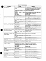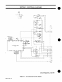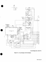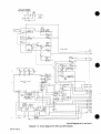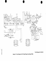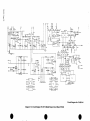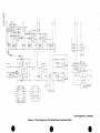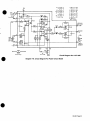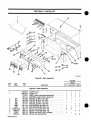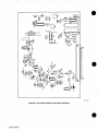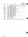
1
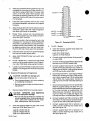
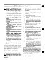
Millerfi
January
1991
FORM: OM-531C
Effe ctive With Serial No. JK674521
MODEL: SP-1
SP-2
SP-3
S P-3-50
SP-4
S P-4-50
~OLDP,~
OWNERS
IMPORTANT:
MANUAL
Read and understand the entire contents of both this manual
and the power source manual used with this unit, with special
the safety material throughout both manuals, before installing,
emphasis on
operating, or
maintaining this equipment. This unit and these instructions are for use only
by persons trained and experienced in the safe operation of welding equip
ment. Do not allow untrained persons to install, operate, or maintain this unit.
Contact your distributor if you do not fully understand these instructions.
TC-046 483
MILLER ELECTRIC
A Miller
Mfg. Co.
Group Ltd.. Company
P.O. Box 1079
Appleton,
WI 54912 USA
Tel. 414-734-9821
PRINTED IN U.SA.
.
LIMITED WARRANTY
EFFECTIVE: AUGUST
This warranty supersedes all
MILLER warranties and is exclusive with
previous
LIMITED WARRANTY
6, 1990
Subject
to the terms and conditions
hereof. MiLLER Electric Mfg. Co.. Appleton. Wisconsin war
rants to its Distributor/Dealer that all new and unused
Equipment furnished by MILLER is free from defect in
no
other guarantees
cases.
which have
transportation
year. 2000 hour warranty.
warranties
expressed
or
implied.
In the case of MILLERs breach of warranty or any other duty
with respect to the quality of any goods, the exclusive remedies
therefore shall be. at MILLERs option (1) repair or (2) replace
ment or. where authorized in writing by MILLER in appropriate
workmanship and material as of the time and place of delivery
by MILLER. No warranty is made by MILLER with respect to
engines, trade accessories or other items manufactured by
others. Such engines, trade accessories and other items are
sold subject to the warranties of their respective manufacturers.
if any. All engines are warrantied by their manufacturer for two
years from date of original purchase. except Deutz engines
a one
or
(3)
the reasonable cost of
repair
authorized MILLER
service
authorized service
facility, therefore,
or
replacement
at an
station or (4) payment of or credit
for the purchase price (less reasonable depreciation based
upon actual use) upon return of the goods at Customers risk
and expense. MILLERs option of repair or replacement will be
FOB.. Factory at Appleton. Wisconsin. or F.O.B. at a MILLER
no
compensation for
costs of any kind will be allowed.
Upon receipt
of
notice of
Except as specified below. MILLERs warranty does not apply
components having normal useful life of less than one (1)
year, such as spot welder tips. relay and contactor points.
MILLERMATIC parts thatcome in contactwith the welding wire
including nozzles and nozzle insulators where failure does not
result from defect in workmanship or material.
apparent defect or failure, MILLER shall instruct the
claimant on the warranty claim procedures to be followed.
to
MILLER shall be
required to honor warranty claims on war
Equipment in the event of failure resulting from a defect
within the following periods from the date of delivery of
Equipment to the original user:
ranted
EXPRESS WARRANTY NOT PROVIDED HEREIN
WARRANTY, GUARANTY OR REPRE
SENTATION AS TO PERFORMANCE, AND ANY REMEDY
FOR BREACH OF CONTRACT WHICH. BUT FOR THIS
PROVISION. MIGHT ARISE BY IMPLICATION, OPERATION
OF LAW. CUSTOM OF TRADE OR COURSE OF DEALING,
ANY
AND ANY IMPLIED
INCLUDING
ANY
IMPLIED
WARRANTY
OF
.
MERCHAN
TABILITY OR OF FlTNESS FOR PARTICULAR PURPOSE,
1.
Arc welders, power
2.
components
Load banks
3.
Original
main power rectifiers
(labor
1 year
4.
All
sources,
robots, and
1 year
3 years
5.
guns. feeder/guns and torches
All other MILLERMATIC Feeders
6.
Replacement
7.
Batteries
or
repair
a
.
.
days
1 year
60
days
6 months
matter of
by
90
.
parts, exclusive of labor
provided that MILLER is notified in
of the date of such failure.
As
writing
within
thirty (30) days
general policy only. MILLER may honor claims
original user within the foregoing periods.
the
ANY
AND
ALL
RESPECT
TO
EQUIPMENT
FURNISHED BY MILLER IS EXCLUDED AND DISCLAIMED
BY MILLER.
WITH
only)
welding
submitted
1 year
AS
EXPRESSLY PROVIDED BY MILLER IN
PRODUCTS ARE INTENDED FOR
ULTIMATE PURCHASE BY COMMERCIAL/INDUSTRIAL
USERS AND FOR OPERATION BY PERSONS TRAINED
AND EXPERIENCED IN THE USE AND MAINTENANCE OF
WELDING EQUIPMENT AND NOT FOR CONSUMERS OR
CONSUMER USE. MILLERS WARRANTIES DO NOT
EXTEND TO, AND NO RESELLER IS AUTHORIZED TO
EXTEND MILLERS WARRANTIES TO, ANY CONSUMER.
EXCEPT
WRITING,
MILLER
_1
I
.1
I
OM-531C
1/91
RECEIVING-HANDLING
Before unpacking equipment, check carton for any damage that may have occurred during shipment. File any
claims for loss or damage with the delivering carrier.
Assistance for
settling claims may be obtained
equipment manufacturers Transportation Department.
filing
spaces to record the Model Designa
Style Number of your unit. The infor
mation is located on the data card or the nameplate.
Use the
following
tion and Serial
or
or
from the distributor and/or the
Model
________________________________
Serial
When requesting information about this equipment, al
ways provide the Model Description and Serial or Style
or
Style
No.
____________________
Date of Purchase
______________________
Number.
TABLE OF CONTENTS
Section No.
SECTION 1
Page
SAFETY PRECAUTIONS AND SIGNAL WORDS
1-1.
General Information And
1-2.
Safety
SECTION 2
2-1.
SECTION 3
3-1.
3-2.
3-3.
3-4.
3-5.
3-6.
3-7.
Alert
4-1.
4-3.
4-4.
4-5.
4-6.
4-7.
4-8.
4-9.
4-10.
And
1
1
SPECIFICATIONS
2
Description
INSTALLATION
Field Installation Instructions For
Power Source
Installing Programmer Onto
Welding
2
Field Installation Of Pulser Into SP-1 And SP-3
3
Programmers
Remote Emergency Stop Switch Connections (Switch Not Supplied)
Remote Downslope Initiation Switch Connections (SP-3 And SP-4
Models) (Switch Not Supplied)
Remote Hand Switch Connections (SP-1 And SP-2 Models)
Remote Start Control Connections (SP-3 And SP-4) (Switch Not
Supplied)
Timed Normally-Open And Normally-Closed Contacts (SP-3 And
SP-4 Models)
SECTION 4OPERATOR
4-2.
Symbol
Safety
Signal Words
6
6
7
7
7
CONTROLS
Programmer Switch
Starting The Unit
Stopping The Unit
Electroslope (All Models)
Remote Downslope Initiation Switch (SP-3 And SP-4 Models)
Pulser (SP-2 And SP-4 Models)
Sequencer (SP-3 And SP-4 Models)
SMAW/GTAW Switch (SP-1 And SP-2 Models)
Auto/Manual Switch (SP-3 And SP-4 Models)
Remote Hand Switch RHS-46 (SP-1 And SP-2 Models)
8
8
8
9
10
10
11
11
11
11
No.
Section No.
SECTION 5
Page
No.
SEQUENCE OF OPERATION
5-1.
Control
12
5-2.
Gas
12
5-3.
Setup Checklist
Tungsten Arc Welding (GTAW)
Shielded Metal Arc Welding (SMAW)
5-4.
Shutting
SECTION 6
14
Down
14
MAINTENANCE & TROUBLESHOOTING
6-1.
ElectronicTimers
14
6-2.
Circuit Board
15
6-3.
Troubleshooting
SECTION 7
Replacement Procedures
16
ELECTRICAL DIAGRAMS
Diagram
Diagram
Diagram
Diagram
Diagram
Diagram
Diagram
Diagram
SECTION 8
7-i. Circuit
18
7-2
19
Diagram For SF-i Models
Diagram For SP-2 Models
7-3. Circuit Diagram For SP-3 And SP-4 Models
7-4. Circuit Diagram Far SF-i Model Sloper Circuit Board PC500
7-5. Circuit Diagram For SP-2 Model Sloper Circuit Board PC500
7-6. Circuit Diagram For SP-3 Model Sloper Circuit Board PC500
7-7. Circuit Diagram For SP-4 Model Sloper Circuit Board PC500
.
Circuit
7-8. Circuit
Diagram
For Pulser Circuit Board
20
.
21
.
22
.
23
.
24
25
PARTS LIST
Figure
Figure
Figure
8-1. Main
Assembly
(Sloper
8-2. Circuit Card
26
And Pulser
Illustrated)
8-3. Pulser Control
28
31
V
LIST OF CHARTS AND TABLES
Table 2-i.
1
Chart 4-i. Weld
9
Table
Table
Table
Specifications
Cycle Timing
5-i. Welding Power Source Control Checklist
5-2. Programmer Control Check!ist
6-i .Troubleshooting
13
13
17
S
SECTION 1
1-1.
SAFETY PRECAUTIONS AND SIGNAL WORDS
GENERAL INFORMATION AND SAFETY
1-2.
SAFETY
ALERT
SYMBOL
AND
SIGNAL
WORDS
A.
General
The
following safety alert symbol and signal words are
throughout this manual to call attention to and iden
different
levels of hazajd and special instructions.
tify
used
presented in this manual and on various la
and
bels, tags,
plates on the unit pertains to equipment
design, installation, operation, maintenance, and
troubleshooting which should be read, understood, and
followed for the safe and effective use of this equipment.
Information
B.
a
safety alert symbol
is used with the
signal
words WARNING and CAUTION to call atten
tion to the
safety
statements.
Safety
The installation,
operation, maintenance, and trouble
shooting of arc welding equipment requires practices
and procedures which ensure personal safety and the
safety of others. Therefore, this equipment is to be in
stalled, operated, and maintained only by qualified per
sons in accordance with this manual and all applicable
codes such as, but not limited to, those listed at the end
of Section 1
Safety Rules For Operation Of Arc Weld
ing
This
Power Source in the
welding
power
source
a
WARNING statements identify procedures or
practices which must be followed to avoid seri
ous personal injury or loss of life.
a
CAUTION statements identify procedures or
practices which must be followed to avoid minor
personal injury or damage to this equipment.
IMPORTANT
Owners
statements
identify special instructions
operation of this equip
necessary for the most efficient
Manual.
ment.
SECTION 2
Table 2-1.
SPECIFICATIONS
Specifications
Weight
Power
Net
Operates
From Welding
Power Source Control
Voltages
I
Ship
75 lbs.
78 lbs.
(34 kg)
(35.4 kg)
TC-046 483
Figure
2-1.
Specifications
OM-531
Page
1
DESCRIPTION
2-1.
The SP-3 is
er
The SP series is
designed to program specific functions
of the Syncrowave welding power source. All of the mod
els are equipped with Electroslope which provides initial
output selection, upslope time control, downslope time
which
equipped with Electroslope, and a Sequenc
provides
electronic control of initial output time,
upslope and weld time, and downslope and final output
time.
.
equipped with Electroslope; Pulser, the
SP-2; and Sequencer, the same as SP-3.
The SP-4 is
same as
control, and final output selection.
locking rear compartment on the Programmer is de
signed for tool and torch storage. The welding power
source lifting eye can be accessed through this compart
The
equipped with Electroslope. The SP-1 must
manually advanced through the welding cycle.
The SP-1 is
be
ment.
welding power source and Programmer are referred
factory
option, the SP is installed on and wired into the welding
power source. Field installation is possible and instruc
The SP-2 is
The
which
to as the unit in this manual. When ordered as a
equipped with Electroslope, and Pulser
provides background output control, pulse per
cent on time, and pulse frequency control. This program
mer must also be manually advanced through the weld
ing cycle.
tions
are
included in Section 3-1.
SECTION 3INSTALLATION
INSTALLING PROGRAMMER ONTO WELD
rection, and align four mounting holes and lead
access hole in Programmer with holes in top cov
ING POWER SOURCE
er
FIELD INSTALLATION INSTRUCTIONS FOR
3-1.
WARNING:
a
(Figures
ELECTRIC SHOCK
3-1 And
3-2)
kill.
can
Shutdown welding powersource, and discon
nect input power employing lockout/tagging
procedures before beginning this installation.
Lockout/tagging procedures consist of padlock
ing line disconnect switch in open position, re
moving fuses from fuse box, or shutting off and
red-tagging circuit breaker or other disconnect
ing device.
5.
Remove
Remove
7.
Drill four 9/32 in.
ing power
in
.
2.
Programmer front panels. Retain all hardware
during this procedure for reinstallation.
power
source
top
cover.
(7 mm) mounting holes
in weld
source cover.
or punch a 2-1/4 in. (57 mm) lead
welding power source cover.
access
hole
Electrical Connections
Locate terminal strip iT in the
welding power
source.
respect to the operator facing the welding power source
and
welding
Drill
8.
with
are
from top of
welding power
6.
1.
left or right,
Programmer
source.
B
as
source.
Using the Programmer as a template, mark four
mounting holes and lead access hole onto weld
ing power source top cover.
This unit and these instructions are for use only
by persons trained and experienced in the safe
methods of working on welding equipment.
IMPORTANT: All directions such
welding power
4.
Do not touch live electrical parts.
Do not allow untrained persons to install this
unit.
of
Connect the following leads from 12-socket
PLG2 to corresponding terminals on iT:
re
plug
11 to 1T11
moved
20 to 1T20
32 to 1T32
a
CAUTION: METAL FILINGS AND/OR TOOL
CONTACT WITH INTERNAL COMPONENTS
can damage unit.
Cover internal components.
Clean unit, and remove internal covering
terial before resuming operation.
ma
68 to 1T68
IMPORTANT: It may be necessary to cut
ties to locate leads.
3.
Locate leads Bi and 4
sleeving
splices.
Slide
back
wiring harness
coming from pilot light PL1.
on
these leads to expose
A. Mechanical Procedures
1.
Remove top
2.
Remove both side
cover
from
a
Programmer.
panels
from
welding power
source.
3.
Programmer
source
with front control
on
top of welding power
panels facing
same
di-
can
damage
unit.
Do not allow solder to fall into unit.
areas of unit when
connections.
Cover exposed
or
Place
OM-531 Page 2
CAUTION: SOLDER
unsoldering
Remove
covers
ing operation.
soldering
and clean unit before
resum
.
Solder leads Bi and 4 from PLG2 to correspond
ing leads from PL1. Slide sleeving back into posi
4.
tion after
soldering.
Insert lead 160 from PLG4 into hole 27 at RC3. Be
20.
one
coming from remote control recep
tacle RC2. Cut lead 11 approximately 6 in. (152
mm) from RC2.
coming
8.
Tape
wiring
har
C.
ness.
1.
Locate lead 31 at contactor control switch S4.
2.
Connect lead 31 from PLG2 to S4
as
(ground) coming from PLG4 to
mounting bolts holding circuit board en
in place.
or
tie leads to
harness to
existing wiring
maintain lead dress and to avoid contact with hot
from
or
Insulate free end of lead 11 and tie into
7.
lead 160 is locked in RC3.
of the
closure
22.
Splice lead 144 from PLG2 to lead 11
RC2.
6.
on
Connect lead 42
21.
Locate lead 11
5.
terminal
sure
moving parts.
Final Installation Procedures
Reinstall the
Place the
er
follows:
welding
power
source cover.
Programmer on top of the welding pow
supplied mounting
source, and secure with
screws.
a.
Disconnect
existing lead
b.
Reconnect lead 31
31 from S4.
12-pin plug PLG1 and 9-pin plug PLG3
Programmer through lead access hole into
welding power source.
Route
3.
connector on
c.
Install
31
9.
10.
new
piggyback
was
piggyback
from
lead 31.
connector onto S4 where lead
removed in Step
Connect PLG1
4.
welding
a.
5.
Solder lead 123 from PLG2 to Ri where lead 109
6.
welding power
Reinstall side
removed.
lead 109
coming from
9-socket
leads 107 to lead 107
14.
Splice
15.
Locate lead 114 at start amperage switch SlO.
Connect lead 114 from PLG4 to 510 as follows:
b.
existing lead
Disconnect
Install
piggyback
16.
was
Connect the
a
following
on
Step
source
OF
PULSER
INTO
(Figures
3-3)
can
kill.
parts.
welding powersource,
and discon
ing line disconnect switch in open position, re
moving fuses from fuse box, or shutting off and
red-tagging Circuit breaker or other disconnect
ing device.
are for use only
by persons trained and experienced in the safe
methods of working on welding equipment.
corre
All
directions, such
as
left
or
right,
are
with respect to the operator facing the welding power
source and Programmer front panels. Retain hardware
and 118. Slide
sleeving
splices.
back
just behind right
on
are
leads 117
these leads to
from PLG4 to corre
welding power source is equipped
with Pulser, insulate end of lead 160 coming from PLG4,
and tie into Programmer wiring harness.
on
RC3.
A.
during
this
procedure for reinstallation.
Mechanical Procedures
ex
IMPORTANT: If the
receptacle RC3
removed
1.
Splice leads 117 and 118
sponding leads from T2.
Locate
power
This unit and these instructions
leads from PLG4 to
iT:
Locate control transformer T2
cate hole 27
panels onto welding
Programmer.
input power employing lockout/tagging
procedures before beginning this installation.
Lockout/tagging procedures consist of padlock
a.
end of 1 T. Green transformer leads
19.
PLG4 in
onto
Shut down
piggyback
81 to 1T81
18.
to
nect
IMPORTANT:
pose the
Programmer
source.
Do not allow untrained persons to install this
unit.
114 from 510.
86 to 1T86
17.
PLG2 in
Do not touch live electrical
connector onto SlO where
removed in
sponding terminals
to
WARNING: ELECTRIC SHOCK
coming from PLG4.
Reconnect lead 114 (from Step a) to
new lead 114.
lead 114
Programmer
INSTALLATION
3-1 thru
connector on
c.
from
source.
SP-1 AND SP-3 PROGRAMMERS
Solder lead 115 from PLG2to Ri where leads 107
were removed.
a.
cover
FIELD
3-2.
Locate leads 107 at Ri. Unsolder leads from Ri.
13.
power
Connect PLG3 from
and
Splice lead 109 to
plug PLG4.
12.
to
Locate lead 109 at main amperage control Ri.
Unsolder lead from Ri.
was
11.
(from Step a)
at circuit board PCi. Lo
2.
Remove top cover from
Remove both side
Programmer.
panels from the welding power
source.
a
CAUTION~ METAL FILINGS AND/OR TOOL.
COI~3TACT WITh INTERNAL COMPONENTS
can
damage-unit.
Cover internal components.
Clean unit and remove internal covering
terial before resuming operation.
OM-531
ma
Page
3
1
provided in the front panel but not in the
nameplate for mounting the Pulser controls. Lo
cate the four prepunched holes in the lower right
corner of the front panel. Mark locations onto
nameplate by applying pressure from rear with a
sharp tool. Punch or drill holes of the same size in
the nameplate.
Holes
3.
are
3
Leadl34
LeadbOl
Rotate Pulser controls
fully counterclockwise,
and install
at
ers
supplied knobs onto shafts
zero (0) or minimum.
with
.
1210
11
100
100
18~0
20100
22 10
~i.24IQ0
912610
13
15
16
Apply the large label with control callouts onto the
nameplate. Apply label with model designation
onto lower right corner of nameplate.
6.
7
14
hardware.
5.
8100
10100
assembly from the rear of the
panel/nameplate, and secure with supplied
front
5
_______
Install the Pulser
4.
0
21
23
25
27
28
Leacj83
point
17
19
29
4
Lead 84
TA.046 965
A hole is
provided in the front panel but not in the
nameplate for mounting the ELECTROSLOPE
switch S52. Locate the hole to the right of the elec
troslope controls. Mark location onto nameplate
by applying pressure from rear with sharp tool.
Punch or drill hole of same size in the nameplate.
7.
Install the switch onto the front
8.
from
rear
with switch
keyway
Receptacle RC5O
3-1.
Figure
For SP-1 Models:
3.
a.
Insert the
following supplied
loose leads into
RC5O (see Figure 3-1).
panel/nameplate
Lead 164 to RC5O Hole 6
down.
Lead 501 to RC5O Hole 26
Apply ELECTROSLOPE
nameplate.
9.
label
over
switch onto
b.
Connect
on
For SP-1 Models
10.
relay CR56
partition in the Program
using supplied hardware.
under CR56 label
Locate circuit board PC500
11.
partition
in the
c.
d.
on
Programmer.
right side of center
Remove and discard
CAUTION: SOLDER
Programmer
can
damage
e.
unit.
Connect
soldering
Remove
covers
and clean unit before
resum
f.
31 to ELECTRO
lead 139 to
existing
lead
Remove header RC5O from
mounting
bracket.
CAUTION:
can cause
Be
existing lead 144 from rectifier SR3.
Slide the supplied tubing onto lead 144. Con
nect the female terminals from existing lead 144
to the male terminals on
IMPROPER LEAD INSERTION
receptacle
g.
ing end
h.
Insert the
following
leads from the pulser circuit
board into RC5O (see
Figure 3-1):
Lead 83 to RC5O Hole 28
Lead 84 to RC5O Hole 29
Lead 134 to RC5O Hole 24
Connect
supplied
lead 144.
connection. Connect remain
supplied lead 156
where lead 144
tacle, rotate terminal 180 and reinsert.
4
over
sure
correct
lock in
Page
tubing
ing end of lead 144 to S52 (see Figure 3-2).
Connect short lead 144 to S52 (see Figure 3-2).
equipment damage.
that lead terminals are inserted into
hole. If a terminal does not
place when inserted into the recep
splice. Connect re
lead 139 to S52 (see Figure
Disconnect
Slide
OM-531
Splice supplied
maining end of new
3-2).
ing operation.
2.
supplied loose lead
139 at RC5O and insulate
Cover exposed areas of unit when
unsoldering connections.
a
to the center
the PULSER switch S400.
Cut existing lead 1394 in. (102 mm) from RC5O.
Disconnect remaining end from CR55 and dis
card.
Do not a/low solder to fall into unit.
or
1.
remaining end of lead 501
on
of STOP push button switch PB51.
Electrical Procedures In
a
Connect
terminal
SLOPE switch S52 (see Figure 3-2). Solder re
maining end of lead 31 to the common terminal
PC500.
B.
end of lead 164 to terminal 7
Install control
only:
to the front of the center
mer
remaining
relay CR56.
to terminal on SR3
removed. Connect remain
of lead 156 to S52
(see Figure 3-2).
Connect supplied lead 155 to terminal A on
CR56. Connect remaining end of lead 155 to
S52
i.
was
(see Figure 3-2).
Connect supplied lead 157 to terminal A on
CR55. Connect remaining end of lead 157 to
S52 (see
Figure 3-2).
Lead
Top
Connect
q.
144-(Iong)
supplied
lead 163 to the terminal
S50 where lead 132
maining
Lead
removed. Connect
was
end of lead 163 to terminal 9
on
re
CR56.
on
For SP-3 Models
4.
a.
Connect supplied lead 501 to terminal 2 on
CR55. Connect remaining end of lead 501 to
center terminal of PULSER switch S400.
b.
Connect
supplied lead 81 to terminal
remaining end of lead 81
8
CR55. Connect
on
to the
top terminal of S400.
Connect supplied long~lead 1 to terminal 13
INITIAL AMPERAGE timer TD51. Connect
c.
Rear View Of
Switch
Lead 156
maining
TA-046 964
on
re
end of lead 1 to ELECTROSLOPE
switch S52
Figure
3-2. Electrical Installation Of
Electroslope
1 to S52
Switch S52 in SP-1 MODELS
j.
Disconnect
existing
male terminals
maining
on
end of
existing lead 32 to the
new
lead 32 to terminal B
on
1.
Disconnect
2.
Connect lead 109 (from
on new
piggyback
where lead 109
Cut off
existing
RC5O. Unsolder
Connect supplied lead 71 to 50T71 Connect re
maining end of lead 71 to S52 (see Figure 3-3).
f.
Connectsupplied
.
Step 1)
lead 130 4 in.
remaining
155 from terminal 3
on
piggy
1.
Connect terminal with two leads to termi
nal A on CR56.
S50
2.
Connect shorter lead to terminal 3
onto
removed in
existing lead
Figure
CR50 and terminal A on CR56 and discard.
Connect supplied lead 155 as follows:
lead 109
connector
was
to
lead 161 to5OTl6l.Connect
end of lead 161 to S52 (see
Disconnect
g.
lead 109 from S50.
existing
back connector
Install
e.
remaining
3-3).
Connect supplied lead 109 to terminal 5 on
CR56. Connect remaining end of lead 109 to
PROGRAMMER switch S50 as follows:
3.
Remove jumper link between terminals 71 and
161 on terminal strip 50T.
supplied lead 32. Connect re
CR56.
k.
d.
lead 32 from SR3. Connect
the female terminals from
(see Figure 3-3). Connect short lead
(see Figure 3-3).
Step
1.
on
CR50.
(102 mm) from
existing lead
Connect remaining lead to S52 (see
3.
end of
Figure
3-3).
130 from the FINAL AMPERAGE control R50
ing end of
m.
new
lead 130 to terminal 4
Splice supplied lead
158 to
existing
on
TD51. Connect
S52 (see Figure 3-3).
CR56.
lead 130 at
on
supplied lead 160 to terminal 6 on CR56.
remaining end of lead 160 through access
in bottom of Programmer into welding power
Connect
5.
Route
RC5O, and insulate splice. Connect remaining
end of lead 158 to terminal 12
Connect supplied lead 157 to terminal 9 on
remaining end of lead 157 to
h.
and discard. Solder supplied lead 130 to R50
where lead 130 was removed. Connect remain
hole
CR56.
source.
n.
Cut off
existing lead 133 4 in. (102 mm) from
RC5O. Disconnect remaining end of lead 133
from S50 and discard. Splice supplied lead 133
existing lead 133 at RC5O and insulate splice.
Connect remaining end of new lead 133 to ter
Rear View Of
Switch
Lead 155
Top
to
minal 3
on
CR56.
a.
Connect supplied lead 165 to the terminal on
S50 where lead 133 was removed. Connect re
maining end of lead 165 to terminal 11 on CR56.
p.
Cut
existing
lead 1324 in. (102 mm) from RC5O.
Lead 161
I
V~F
4
Lead 157
H
Lead 71
t~r
Lead 1
(long)
-l
Disconnect
remaining end of lead 132 from S50
and discard. Splice supplied lead 159 to existing
lead 132 at RC5O and insulate splice. Connect
one of the remaining ends of new lead 159 to
terminal 2 on CR56. Connect remaining end of
new
lead 159 to terminal 1
on
CR56.
Lead 1 (short)
TA-046 963
Figure
3-3. Electrical Installation Of
Electroslope
Switch S52 in SP-3 Models
OM-531 Page 5
pulser module to the
Programmer circuit
Connect lead 42 from the
6.
threaded mounting
board PC500.
Connect lead 132 from the pulser module to ter
minal 10 on CR56.
7.
REMOTE EMERGENCY STOP SWITCH CON
3-3.
NECTIONS (Switch Not Supplied)
spacer for
a
WARNING: ELECTRIC SHOCK
Do not touch live electrical
Shutdown
9.
Align supplied PC500
Thread leads 81, 86, and 114 from the pulser
module, through the access hole in the bottom of
10.
the
welding power source,
programmer, and into the welding power
source.
and discon
this installation.
Lockout/tagging procedures consist of padlock
ing line disconnect switch in open position, re
moving fuses from fuse box, or shutting off and
red-tagging circuit breaker or other disconnect
and insert into RC5O. Se
PC500 to standoffs.
cure
parts.
procedures before beginning
Reinstall RC5O.
kill.
input power employing lockout/tagging
nect
8.
can
ing device.
All directions, such
IMPORTANT:
left
as
or
right,
are
respect to the operator facing the welding power
and Programmer front panels. Retain all hard
ware removed during this procedure for reinstallation.
with
source
C.
Welding
Power Source Electrical Connections
A remote emergency stop switch may be installed into
the Programmer. If remote emergency stop capability is
For Models Prior To Serial No. JA432849:
desired, obtain switch and proceed
Splice supplied leads 81, 86, 114, and 160 to
corresponding leads routed into the welding
a.
power
b.
source
from the
For SP-1 and SP-2 Models: Obtain a normallySP-3 and
open, momentary-contact switch. For
1.
Programmer.
SP-4 Models: Obtain
a
normally-closed,
momen
tary-contact switch.
Connect leads 81 and 86 to corresponding ter
minals on terminal strip iT in the welding power
2.
Remove
source.
3.
Route leads from switch
Connect lead 114 to the START AMPERAGE
switch SlO as follows:
c.
follows:
as
Programmer top
cover.
through
access
hole
on
left side of Programmer.
Locate terminal
4.
strip 50T
left side of center
on
partition.
Disconnect
2.
Reconnect lead 114
back connector
Install
3.
Locate
edge
(from Step 1)
on new
piggyback
where lead 114
d.
lead 114 from SlO.
existing
1.
connector
onto
6.
For SP-3 and SP-4 Models: Remove jumper link
between terminals 66 and 77 on 50T, and connect
switch leads to 50T66 and 50T77.
7.
Reinstall Programmer top
8.
Resume
SlO
removed in Step 1.
receptacle RC3
For SP-1 and SP-2 Models: Connect leads from
switch to terminals 31 and 148 on 50T.
piggy
lead 114.
connector
was
to
5.
at cir
cuit board PCi. Insert lead 160 into hole 27 on
RC3. Be sure that terminal on lead 160 has
3-4.
a.
Discard
supplied
a
loose leads 81, 86, 114, and
Programmer
into
plug PLG3
Lockout/tagging procedures consist of padlock
ing line disconnect switch in open position, re
follows:
moving
Be
4.
OM-531
sure
tie
new
leads to
IMPORTANT:
existing wiring
that leads will not touch hot
Reinstall the welding power
and Programmer top cover.
Page
6
circuit breaker
or
shutting off and
other disconnect
or
ing device.
source
or
harness.
moving.
side
panels
All directions, such
to the
as
left
or
right,
are
operator facing the welding power
respect
and Programmer front panels. Retain all hard
ware removed during this procedure for reinstallation.
with
or
fuses from fuse box,
red-tagging
Lead 114 to Socket 5
Lead 160 to Socket 7
Tape
kill.
can
Do not touch live electrical parts.
welding powersource, and discon
input power employing lockout/tagging
procedures before beginning this installation.
Lead 81 to Socket 8
Lead 86 to Socket 6
3.
WARNING: ELECTRIC SHOCK
nect
Insert leads from
as
Supplied)
Not
Shutdown
160.
b.
REMOTE DOWNSLOPE INITIATION SWITCH
(SP-3 And SP-4 Models)
(Switch
For Models Effective With Serial No. JA432849:
operation.
CONNECTIONS
locked into RC3.
2.
cover.
source
A
normally-open, momentary-contact switch
may be
used for remote downslope initiation of the Programmer.
.
This switch may be manually operated or may be a fix
a-mounted limit switch. If remote downslope initiation
~ desired, obtain switch and
1.
Remove
proceed
Programmer top
Route leads from switch
2.
left
4.
mer rear
panel.
Remove
jumper links
162
on
follows:
Terminals:
cover.
through
on
access
left side of
Program
Reinstall
Programmer top
7.
Resume
operation.
3-6.
HAND
And SP-2
A
DelayedN.C.
5 & 4
Delayed NC.
4 & 3
Delayed
SWITCH
as
relay contacts, pro
follows:
CONNECTIONS
WARNING:
a
Models)
fully
ELECTRIC SHOCK
Do not touch live electrical
SP-4) (Switch
Not
Supplied)
normally-open, momentary-contact switch may
Programmer. If
mote start control is
red-tagging circuit breaker
ing device.
be
re
desired, obtain switch and make
connections between
pins A and B of five-pin Amphenol
plug supplied with welding power source. Align keyways, insert plug, and rotate threaded collar clockwise.
IMPORTANT:
or
other disconnect
ware
TIMED NORMALLY-OPEN AND NORMALLY-
CLOSED CONTACTS (SP-3 And SP-4 Mod
1.
2.
All timers have
All
to the
during
removed
IMPORTANT:
relay contacts available for control of ex
ternal equipment such as movable fixtures. Equipment
can only be connected to timer relay contacts that are
not already in use. Each timer has instantaneous con
tacts that close when power is applied to the timer, and
parts.
directions, such as left or right, are
operator facing the welding power
respect
source and Programmer front panels. Retain, all hard
with
lay
els) (Figure 3-4)
kill.
welding powersource, and discon
nect input power employing lockout/tagging
procedures before beginning this installation.
Lockout/tagging procedures consist of padlock
ing line disconnect switch in open position, re
moving fuses from fuse box, or shutting off and
REMOTE START CONTROL CONNECTIONS
And
can
Shutdown
clockwise.
used for remote start control of the
3-7.
NO.
remote hand
and rotate collar
(SP-3
12&11
To make connections to the timer
switch, RHS-46, connects to
the remote control receptacle on the welding power
source. To make connections, align keyways, insert
plug,
Delayed NO.
*Normally Closed Contacts
~NormaIIy Open Contacts
cover.
ceed
supplied
11 & 13
7 & 6 Instantaneous N.C.
between terminals 64 and
6.
The
1,2 & 15 Provide Power To Timer
6 & 8 Instantaneous NO.
Connect leads from switch to terminals 31 and 64
on terminal strip 50T.
(SP-1
follows:
14 & 9 Instantaneous N.O.~
hole in
50T.
REMOTE
are as
14 & 10 Instantaneous N.C.*
5.
3-5.
contacts that close when the timer times out.
of Programmer.
rear
Locate terminal strip 50T
3.
as
delayed
Timer terminal functions
this
procedure for
reinstallation.
Equipment can only be connected to
already in use.
re
contacts that are not
Remove
Programmer top
cover.
Route leads from external
cess
hole in left
3.
Locate
4.
Reinstall
rear
appropriate
(see Figure 3-4).
of
equipment through
Programmer.
timer and make connections
Programmer top
14
ac
cover.
13 12 11
10
9
8
7
2
5
6
15
16
0
0
0
0
0
~STANTKKE0US
CO~~TKC~S
0
C)
0
OELKVED COCCTKC~S
0
1
OWER SU~LV
3
4
CLOCK
TA.114 384
Figure
3-4. Timer Rear View
OM-531 Page 7
SECTION 4
Programmer Initial Amperage
Switch
OPERATOR CONTROLS
Upslope Time
Control
Downslope
Final
Time
Control
Control
Amperage Electroslope
Control
Switch
Auto-Manual
Switch
Start Push
Button
Stop
Push.
Button
Upslope And Weld
Amperage Time
Downslope And
Final Amperage Time
Pulser Switch
Background
Amperage Control
% On Time Control
Pulses Per Second Control
*SMAW/GTAW Switch On
SP-1 And SP-2 Modela
.
TC-046 482
Figure
PROGRAMMER SWITCH
4-1.
4-1. Front Panel Controls
(Figure 4-1)
When the PROGRAMMER switch is in the ON position,
the Programmer is energized and ready to be pro
grammed for the welding sequence. When in the OFF
position, the programmer functions are not available and
only
the
a
welding
power source controls
are
functional.
power
also used to
cycle
the
Programmer through
be started
pressing
injury.
cations and connections.
4-3.
are
three ways to start the program: 1.) START
on the Programmer, 2.) Remote
cycle
can
by using momentarily
specifi
the RHS-46. See Section 3-5 for switch
STOPPING THE UNIT
(Figure 4-1)
normal weld program is run, the Programmer
automatically resets to OFF at the end of the weld. There
When
STARTING THE UNIT (Figure 4-1)
the various
weld conditions.
The weld
position causes the Programmer to
automatically cycle through the preset program
when the welding power source contactor is
closed regardless of the PROGRAMMER switch
position.
welding
The weld cycle begins when the START push button on
the Programmer is pressed. The START push button is
CAUTION: INCORRECT SWITCH POSITION
equipment damage and personal
The AUTO
There
remote start switch connected to
source.
can cause
Place AUTO/MANUAL switch in the MANUAL
position when the PROGRAMMER switch is
in the OFF position.
4-2.
3).
source,
a
two ways to stop the unit while welding: 1.) the STOP
push button switch on the Programmer, and 2.) a remote
emergency stop switch internally connected to terminal
strip iT in the Programmer.
are
The weld cycle stops and the unit resets when the STOP
switch on the Programmer is pressed.
The weld
cycle
can
be
stopped using
a
remote
emer
push button switch
gency stop switch. See Section 3-3 for switch specifica
Hand Switch RHS-46 connected to welding power
tions and connections.
OM-531
Page
8
Chart 4-1. Weld
Automatic
Cycle Timing
Operation Using Electronic Timers
r
J
Manual Operation Using Remote Hand Switch (RHS-46)
POINT FUNCTION
L
A
Programmer START
B
Preflow timer in the
gins
C
source
be
to time.
Preflow ends.
closes.
D
power
Welding power
High frequency available.
source
AMPERAGE
control
active.
Pulsing
ends.
button pressed.
welding
FINAL
TB-046 960
M
Final amperage time.
N
Arc
extinguished. Postffow timer
source begins to time.
in
welding
power
contactor
Arc started. INITIAL AMPERAGE and INITIAL
0
Postflow time.
P
Weld sequence ends. Unit resets.
AMPERAGE TIME controls active.
POINT SEQUENCE
E
Initial amperage time.
F
UPSLOPE TIME and UPSLOPE AND WELD
AMPERAGE TIME controls active. Pulsing
welding power source times.
power source contactor closes. High fre
quency available. Arc starts and INITIAL AM
PERAGE control is active.
Preflow timer in the
1.
Welding
starts if Pulser is ON.
G
Upslope time.
H
Weld time starts. Weld condition reached. Pul
UPSLOPE TIME control active. Pulsing starts if
Pulser is on. Weld condition reached. Pulser con
2.
ser
4-4.
controls may be
adjusted.
trols may be
I
Weld time.
J
DOWNSLOPE TIME and DOWNSLOPE AND
FINAL AMPERAGE TIME controls active.
K
Downslope time.
ELECTROSLOPE
DOWNSLOPE TIME control active. FINAL AM
3.
PERAGE control active.
Arc
4.
4-1 And
4-2) (All
B.
Pulsing
ends.
extinguished. postflow timer in welding
source
(Figures
adjusted.
power
times. Weld sequence ends. Unit resets.
INITIAL AMPERAGE Control
Models)
The electroslope allows the operator to preset the initial
weld condition, an upslope time, a downslope time, and
a
final weld condition.
A.
ELECTROSLOPE Switch
When the ELECTROSLOPE switch is in the ON
tion, all Programmer controls
are
switch is in the OFF position, the
are not functional.
posi
functional. When the
Electroslope
controls
Amperage circuitry allows the operator to set
starting output that is above or below the setting of the
AMPERAGE CONTROL on the welding power source.
The Initial
a
Rotating the control clockwise increases output. The
scale surrounding the INITIAL AMPERAGE control rep
resents a percentage of the welding power source AM
PERAGE CONTROL and not
an
actual amperage
value.
OM-531
Page
9
20%
C.
UPSLOPE TIME Control
The U PSLOPE TIME control sets the time it takes for the
weld output to slope from the setting of the Programmer
INITIALAMPERAGE control to the setting of the welding
power
50% On Time
Peak
Amperage
AMPERAGE CONTROL.
source
-
Background
Amperage
Rotating the control clockwise increases time. The scale
surrounding the control is calibrated directly in seconds
(0 to 10).
D.
I
Li Li
DOWNSLOPE TIME Control
80% On Time
The DOWNSLOPE TIME control sets the time it takes
J
for the weld output to slope from the setting of the weld
ing power source AM PERAGE CONTROL to the setting
of the
Programmer
-
FINAL AMPERAGE CONTROL.
Rotating the control clockwise increases time. The scale
surrounding the control is calibrated directly in seconds
(0 to 10).
E.
FINAL AMPERAGE Control
The Final
an
On Time
PERAGE CONTROL
finishing
allows the operator to set
setting of the AM
Amperage circuitry
output that is above
or
on
________Pulses Per_________
Second
below the
the
welding
power
source
for
Figure
the weld.
Rotating the control clockwise increases output. The
surrounding the FINAL AMPERAGE control repre
sents a percentage of the welding power source AM
A.
4-2. Pulsed
SA-112 022
Output
PULSER Switch
scale
PERAGE CONTROL and not
an
actual amperage val
ue.
Placing the PULSER
pulsing circuitry
the
switch in the ON
in the
position activates
Programmer. The % ON
TIME, PULSES PER SECOND, and BACKGROUND
AMPERAGE controls must be
4-5.
REMOTE DOWNSLOPE INITIATION SWITCH
(SP-3
And SP-4
If remote control of
Models)
adjusted
to
provide
the
proper pulse width, frequency, and height. When this
switch is in the OFF
position,
the Pulser controls
are
not
functional.
downslope initiation is desired, ob
according to Section 3-4.
B.
% ON TIME Control
tain and install switch
When the Remote
downslope
Downslope Initiation Switch
starts. This allows the
operator
to
is closed,
manually
control the main weld time.
4-6.
PULSER
4-1 And
Pulsing
(SP-2
And SP-4
Models) (Figures
4-2, And Chart 4-1)
refers to the alternate
raising
and
lowering
of the
weld output at a periodic rate. The raised portions of the
weld output are controlled in width, frequency, and
height, forming pulses
of weld output. These
pulses
and
output between them (called the background
amperage) alternately heat and chill the molten weld
The % ON TIME control
and is active
only
Rotating the %
provides pulse
width selection
when the PULSER switch is ON.
ON TI ME control clockwise increases the
peak output time in relation to the entire pulse time. The
scale surrounding this control is calibrated in percent (5
to 95) and represents peak output on time during One
pulse.
C.
PULSES PER SECOND Control
The PULSES PER SECOND control
quency selection and is active
switch is ON.
only
provides pulse fre
when the PULSER
the lower
puddle. The combined effect gives the operator better
control of penetration, bead width, crowning, undercut
ting, and puddle sag in out-of-position welding, especial
ly vertical-up.
Rotating this control clockwise increases pulse frequen
cy. The scale surrounding the PULSES PER SECOND
is calibrated in pulses per second from 0.5 to 10 PPS.
D.
BACKGROUND AMPERAGE Control
The BACKGROUND AMPERAGE control sets the weld
When the Electroslope is used with the Pulser, the initial
and final output are not pulsed. Pulsing begins at
upsiope, continues through the weld portion of the cycle,
downslope is finished.
output background level. The AMPERAGE CONTROL
on the welding power source sets the peak output level
during pulsed welding.
and ends when
IMPORTANT:
while welding.
OM-531 Page 10
The Pulser controls may be adjusted
independently; therefore, it is possi
background amperage higher than the peak
These controls act
ble to set
output.
a
S
Rotating
the control clockwise increases
background
amperage. The scale surrounding the BACKGROUND
AMPERAGE control is calibrated in percentage and
should not be read
as an
The DOWNSLOPE AND FINAL AMPERAGE TIME
control
can
seconds. When this
starts.
SMAW/GTAW SWITCH (SP-1 And SP-2 Mod
els) (Figure 4~1)
SEQUENCER (SP-3 And SP-4 Models) (Fig
ure
postflow
amperage value.
4-8.
4-7.
be set for 00.099.9
control times out,
4-1 and Chart
When the switch is in the SMAW
4-1)
Sequencer times the initial output, starts the
upslope timer in the Electroslope, times the weld portion
of the cycle, starts the downslope timer in the Electro
The
position, weld output re
mains at the level set for the sequence when the
broken during any portion of the program.
When the switch is in the GTAW
sets to the INITIAL AMPERAGE control
To set desired time, press the lever directly below each
tions of the program.
digit.
The levers
These timers
can
are
be
factory
pressed
down
or
pushed
set for the time down and
is broken
2.21 minutes equals 2 minutes and 12.6 seconds.
a
The IN ITIAL AMPERAGE TI ME control allows the oper
ator to choose the length of time that the INITIAL AM
the
Programmer
position, closing the remote conpressing the Programmer
START button will energize the welding
power source, and it will NOT deenergize
unless one of the following is done:
factor device or
can
be set for
0.0099.9
seconds. When this control times out, the
UPSLOPE TIME control in the Electroslope is activated.
1. Place AUTO/MANUAL switch in MANU
AL position
UPSLOPE AND WELD AMPERAGE TIME
The UPSLOPE AND WELD AMPERAGE TIME control
sets the entire time between the start of
upslope
trol to the desired weld time. The total time should be set
the UPSLOPE AND WELD AMPERAGE TIME
con
trol.
Press STOP button
3.
Turn off
welding
on
power
Programmer
source.
When the switch is in the AUTO
position, the unit auto
matically cycles through all programmed sequences
when the START push button switch is pressed. Weld
output is determined by the amperage setting for the
se
quence.
The UPSLOPE AND WELD AMPERAGE TIME control
can
2.
and the
beginning of downslope. To determine the proper time,
add the setting of the Electroslope UPSLOPE TIME con
on
WARNING: UNEXPECTED WELD OUTPUT
can cause serious personal injury or dam
age to weidment or equipment.
If in AUTO
is active.
The INITIAL AMPERAGE TIME control
B.
final por
If use of the Programmer is not desired, AL
WAYS place the AUTO/MANUAL switch in
the MANUAL position.
INITIAL AMPERAGE TIME
on
or
AUTO/MANUAL SWITCH (SP-3 And SP-4
4-9.
1/10 (0.1) minute equals 6 seconds.
PERAGE control
downslope,
Models) (Figure 4-1)
1/100 (0.01) minute equals 0.6 seconds. A setting of
A.
the weld,
up.
stop
mode of operation.
IMPORTANT:
during
is
position, weld output re
setting when the
slope, and times the final output.
arc
arc
be set for 00.099.9
minutes. When this control
times out, the DOWNSLOPE TIME control in the EIec
troslope is activated.
When the switch is in the MANUAL
position, the program
consists of the initial condition, upslope, and an untimed
weld condition. The START push button switch or re
mote start switch must be maintained closed while weld
ing.
C.
DOWNSLOPE AND FINAL AMPERAGE TIME
DOWNSLOPE AND FINAL AMPERAGE TIME
control sets the entire time between the start of downslope and the beginning of postflow. To determine the
proper time, add the setting of the Electroslope DOWNSLOPE TIME control to the desired final amperage time.
The
The total time should be set
on
the DOWNSLOPE AND
FINAL AMPERAGE TIME control.
4-10.
REMOTE HAND SWITCH RHS-46
SP-2 Models)
(SP-1
And
(Chart 4-1)
necessary to press the Remote Hand Switch
RHS-46 each time a new or different weld condition is
It is
desired. This switch allows the operator to manually
control the selection of the welding condition and the du
ration of that condition from
a
remote station.
OM-531 Page fl
SECTION 5
a
WARNING:
ELECTRIC SHOCK can kill;
MOVING PARTS can cause serious injury;
IMPROPER AIR FLOW AND EXPOSURE TO
ENVIRONMENT can damage internal parts.
1.
Install and connect unit
this manual and the
ers
2.
Do not touch live electrical parts.
ANSI Z49.1.
3.
Ventilate to keep from
gases.
If ventilation is inadequate,
breathing device.
HOT
harm
breathing fumes
cause
Connect work clamp to clean, bare metal at
c.
Prepare tungsten electrode according to
ing power source Owners Manual, and
weld
insert
into torch.
and
the weld sequence by setting switches
according to Section 5-1.
Program
approved
METAL, SPATTER, AND SLAG
follows:
Select and obtain proper tungsten electrode.
4.
use
as
b.
body protection.
seriously
welding
workpiece.
hearing.
can
for
Prepare
a.
ARC RAYS, SPARKS, AND HOT SURFACES
can burn eyes and skin, NOISE can damage
FUMES AND GASES
your health.
Manual.
dry insulating gloves and clothing, and wear
welding helmet with proper filter lens according to
Keep
erating.
Warranty is void if the unit is operated with any
portion of the outer enclosure removed.
according to Section 3 of
welding power source Own
Wear
a//covers and panels in p/ace while op
Wear correct eye, ear, and
S
SEQUENCE OF OPERATION
and controls
5.
Turn
6.
Place PROGRAMMER switch in the ON position.
on
the
shielding
gas.
can
fire and burns.
Watch for fire.
Have fire
Place
7.
extinguisher nearby,
and know how
to use it.
Allow work and
equipment to cool before han
Push
8.
dling.
a.
See Section 1
b.
Safety Rules For Operation Of
Power Source in the welding power
source Owners Manual for basic welding safety
information.
Welding
For GTAW mode: The START
CONTROL SETUP CHECKLIST
(Tables
through
5-1
provide the operator with a quick
checklist approach to setting switch positions and con
trols for the Shielded Metal Arc (SMAW) and Gas Tung
sten Arc (GTAW) Welding processes. Specific control
settings depend on the process application.
power source Owners
function of controls.
we/ding
on
5-2.
GAS TUNGSTEN ARC WELDING
a
WARNING: Read and follow safety informa
tion at beginning of entire Section 5 before
OM-531 Page 12
mo
automatically cycles
the weld program.
during
the entire program. The IN
UPSLOPE RATE controls function but the weld
tables
proceeding.
the unit
For MANUAL mode: The Start switch must be
time is
Manual for information
button
ITIAL AMPERAGE TIME and PERCENTAGE
5-2)
IMPORTANT: See the
push
For AUTO mode: Once the Start switch is
held closed
following
remote
or
mentarily closed,
c.
The
power switch in the
Remote Hand Switch RHS-46 must be
momentarily closed each time a new sequence
is desired.
welding operations.
And
source
Programmer START push button or
(see Sections 3-5, 3-6, and 4-2).
switch
Wearers should consult with their doctor be
fore going near arc welding, gouging, or spot
5-1.
power
switch
MAGNETIC FIELDS FROM HIGH AMPER
AGES can affect pacemaker operation.
Arc
welding
ON position.
(GTAW)
manually
controlled. The unit
resets as soon as the Start switch is
downslope
or
final
stops and
opened (no
conditions).
IMPORTANT: For SP- 1 and SP-2 models: If an
age
arc out
any point in the program, the amperage
reverts to that of the INITIAL AMPERAGE control
occurs at
setting
for arc starting. For SP-3 and SP-4 models: If an arc out
age occurs during the initial, upslope, or weld conditions,
the welding power source contactor opens and weld out
put is not available. The Programmer continues to the
end of the cycle and resets.
9.
Adjust
controls
as
necessary.
S
Table 5-1.
Welding
Welding
Power Source Control Checklist
Power Source Controls
SMAW
CONTACTOR Switch
GTAW
OFF
ON
AMPERAGE Switch
As Desired
As Desired
AMPERAGE CONTROL
As Desired
As Desired
OFF
As Desired
CRATER FILL Switch
As Desired
OFF
AMPERAGE Switch
As Desired
OFF
AMPERAGE Control
As Desired
AC BALANCE Control
As Desired
As Desired
0
As Desired
OFF
OFF
HIGH FREQUENCY Switch
*POST FLOW TIME control
*SPOT TIMER Switch
*SPOT TIME Control
Not
PRE-FLOW TIME Switch
Not
Not
Applicable
OFF
PRE-FLOW TIME Control
Not
*PULSER Switch
Not
PULSES PER SECOND Control
*BACKGROUND AMPERAGE Control
Applicable
As Desired
As Desired
Applicable
OFF
OFF
*% ON TIME Control
Apphpable
Applicable
Not
Not
Applicable
Not Applicable
Not
Applicable
Not Applicable
Applicable
AC/DC Selector Switch
As Desired
As Desired
RANGE Switch
As Desired
As Desired
POLARITY Switch
As Desired
As Desired
*If
so
equipped.
Table 5-2.
Programmer Control Checklist
Programmer Controls
PROGRAMMER Switch
SMAW/GTAW Switch
SMAW
GTAW
+ON
OFF
GTAW
SMAW
.
or
AUTO/MANUAL Switch
MANUAL
As Desired
INITIAL AMPERAGE Control
Not
Applicable
As Desired
*INITIAL AMPERAGE TIME
Not
Applicable
As Desired
UPSLOPE TIME Control
Not
Applicable
As Desired
*UPSLOPE AND WELD AMPERAGE TIME
Not
Applicable
As Desired
DOWN SLOPE TIME Control
Not
Applicable
As Desired
*DOWNSLOPE AND FINAL AMPERAGE TIME
Not
Applicable
As Desired
FINAL AMPERAGE Control
Not
Applicable
As Desired
*ELECTROSLOPE Switch
OFF
*PULSER Switch
ON
ON**
As Desired
*% ON TIME Control
As Desired
As Desired
*PULSES PER SECOND Control
As Desired
As Desired
BACKGROUND AMPERAGE Switch
As Desired
As Desired
*lf
so
equipped.
+If pulsing is desired. If a remote control is used, both the peak output and background output are varied by the remote
control in the same proportion as the settings of the Programmer BACKGROUND AMPERAGE control and the welding
power
**If
source
AMPERAGE CONTROL.
Electroslope
is not used,
welding
power
source
START AMPERAGE circuit may be used.
OM-531
Page
13
SHIELDED METAL ARC WELDING
5-3.
(SMAW)
b.
WARNING: Read and follow safety information at beginning of entire Section 5 before
a
For MANUAL mode: The Start switch must be
held closed
proceeding.
pulsing
1.
Install and connect unit
IMPORTANT: If an
er source
ers
2.
Manual.
according
by setting
4.
Place the
power
source
position.
6.
Wear
as
1.
necessary.
dry insulating gloves and clothing, and wear
welding helmet with proper filter lens according to
ANSI Z49. 1.
Prepare for welding
7.
a.
as
Connect work clamp to clean, bare metal at
2.
3.
Select and obtain proper electrode, and insert
into electrode holder.
Push
Programmer START push
switch
a.
button
or
Every six months inspect the labels on
legibility. All precautionary labels must be
in a clearly readable state and replaced
when necessary. See Parts List for part number of pre
cautionary labels.
ELECTRONIC TIMERS
Begin welding.
SHUTTING DOWN
Stop welding
(Figure 6-1)
WARNING: ELECTRIC SHOCK
Do not touch live electrical
can
kill.
Place the
Turn off
shielding gas
1.
Fully
2.
Pull timer out of
3.
To
5.
POWER switch
at source, if
applicable.
supply when
not in use.
set for either 50
Hertz operation
the
model),
loosen two screws
change
on
case.
on
This
timer
faceplate.
requires
a
firm
grip.
from 60 Hertz to 50 Hertz, reconnect
left side of timer to 50 HZ
pin.
change from the time down and stop mode, re
pin on right side of timer to desired termi
nal: Up & Go, Down & Go, or Up & Stop.
To
or
60
the time
To
change time unit, apply slight pressure with a
or pencil point to metal arm in slotted arc on
pen
right
side of timer, and
move arm to
appropriate
unit.
6.
change level of accuracy, use finger force to
white plastic lever located behind timer face
until decimal point is at desired level.
To
move
device,
The electronic timers
14
source
99.9 second or
down and stop mode, and either 00.0
00.0
99.9 minute timing. To change any of these fea
tures, proceed as follows:
parts.
Lockout/tagging procedures consist of padlocking line disconnect switch in open position,
removing fuses from fuse box, or shutting off
and red-tagging circuit breaker or other discon-
Page
reset.
connect
welding power source, and dis
input poweremploying lockout/tagging procedures before inspecting, maintaming, or servicing,
OM-531
welding power
position.
Shut off gas
4.
connect
are factory
(depending on
Programmer to
WARNING:
HIGH CONCENTRATION OF
SHIELDING GAS can harm health or kill.
Shut down
necting
and allow the
Place PROGRAMMER switch in OFF position.
pin
~
necessary.
MAINTENANCE & TROUBLESHOOTING
IMPORTANT:
6-1.
as
remote
(see Sections 3-5, 3-6, and 4-2).
SECTION 6
maintained
controls
source
in the OFF
For SMAW mode: Pulsing starts as soon as the
Start switch is closed if pulsing is selected.
this unit for
output is
the
IMPORTANT: It maybe necessary to manually cycle the
Programmer to the end of the weld program through use
of the START push button switch or Remote Hand
4.
8.
Adjust
by
Switch RHS-46.
follows:
workpiece.
b.
10.
5-4.
controls
welding pow-
switch in the ON
position.
Adjust
occurs, the
outage
welding power
AMPERAGE CONTROL for restarting the arc.
9.
Place PROGRAMMER switch in the ON
welding
switches
to Section 51.
3.
5.
arc
contactor remains closed and weld
available at the level set
the weld sequence
Program
and controls
the entire program. Releas
is selected.
this manual and the
according to Section 3 of
welding power source Own-
during
the Start switch ends the program. Pulsing
starts as soon as the Start switch is closed if
ing
7.
Reinstall timer into case, and
timer
faceplate.
secure screws on
lime Unit
Time Down &
Arm
Stop Pin
60 Hertz Pin
50 Hertz Pin
...
I
~
Figure
6-2.
6-1.
Changing
Timer
Operations
CIRCUIT BOARD REPLACEMENT PROCE
IMPORTANT:
DURES
with
(Figure 6-2)
respect
All directions, such
to the
Retain all hardware removed
If a circuit board is found to be
the
following procedure.
faulty, replace board using
Do not attempt board
a
replacement part.
can
A.
2.
kill.
Shutdown
we/ding powersource, and discon
input power employing lockouVtagging
procedures before inspecting, maintaining, or
servicing.
Lockout/tagging procedures consist of padlock
ing line disconnect switch in the open position,
removing fuses from fuse box, or shutting off and
red-tagging circuit breaker or other disconnect
ing device.
(ESD)
Put
can
on
FORE
properly grounded wrist strap
Perform work
only
a
sure
B.
that
plugs
are
Reinstall
screws
removed in
Programmer top
Pulser Board
2.
Locate and examine
ing position
6-2).
Step
3.
cover.
Replacement
Programmer top
cover.
pulser board noting
mount
and connector locations (see
Figure
plugs straight off board and allow to hang free
wiring harness.
Pull
on
Remove the nuts and lock washers
board, and
area.
5.
Position
6.
remove
new
same
location
Install
new
properly installed and
moved in
can
po
PC500 and insert into RC5O. Secure
new
Remove
4.
aligned.
EXCESSIVE PRESSURE
noting mounting
screws securing PC500 to unit, and
from
PC500
receptacle RC5O.
pull
1.
static-
static-safe work
cover.
receptacle location (see Figure 6-2).
PC500 using
5.
Replacement
Locate and examine PC500
Align
3.
INCORRECT INSTALLATJON or misaligned
plugs can damage circuit board.
Be
are
BE
circuit boards.
at
right,
during this procedure for
Programmer top
4.
damage circuit board.
Transport all circuit boards in proper
shielding carriers or packages.
Remove
Remove the
ELECTROSTATIC DISCHARGE
handling
Board PC500
3.
nect
a
Sloper
sition and
Do not touch live electrical parts.
CAUTION:
or
reinsta//ation.
1-.
WARNING: ELECTRIC SHOCK
left
repair.
Contact the nearest Factory Authorized Service Station
for correct
as
operator facing the unit front panel.
board
as
board
Step
securing the
board from standoffs.
so
that connectors
previously
are
in
noted.
using lock washers arid
nuts re
4.
break circuit
board.
7.
Use
only minimal pressure and gentle move
ment when disconnecting or connecting
board plugs and removing or installing board.
Reinstall plugs onto new board with keyways
aligned. Connectors only go together completely
one
8.
way.
Reinstall
Programmer top
cover.
OM-531
Page
15
Ret. TD-046 484-A
Figure
6-3.
TROUBLESHOOTING (Table 6-1)
a
WARNING: ELECTRIC SHOCK
6-2. Circuit Board
can
kill.
Shutdown
welding powersource, and discon
input power employing lockout/tagging
procedures before inspecting or servicing.
nect
Lockout/tagging procedures consist of padlock
ing line disconnect switch in the open position,
removing fusesfrom fuse box, or shutting off and
red-tagging circuit breaker or other disconnect
ing device.
Allow
can cause severe
burns.
cooling period before servicing.
Troubleshooting
to be
performed only by quali
fied persons.
Itis assumed that the unit
ing
to Section 3 of this
was
properly installec.
accord
manual, the operator is familiar
with the function of controls, the unit was working prop
erly, and that the trouble is not related to the welding
OM-531
Page
16
process. The following table is designed to diagnose and
provide remedies for some of the troubles that may de
velop
Do not touch live electrical parts.
HOT SURFACES
Replacement
in this unit.
Use this table in
conjunction with the circuit diagram
performing troubleshooting procedures. if the
trouble is not remedied after performing these proce
dures, contact the nearest Factory Authorized Service
Station. In all cases of equipment malfunction, the
manufacturers recommendations should be strictly fol
while
lowed.
To
distinguish between welding power source problems
Programmer problems, place PROGRAMMER
switch in OFF position and use welding power source
without Programmer. if the problem still exists, refer to
welding power source Owners Manual or contact the
nearest Factory Authorized Service Station.
and
IMPORTANT: Before
beginning troubleshooting proce
dures, recheck al/switch positions and control settings
and be
cation.
sure
unit is
properly set up
for the
we/ding appli
Table 6-1
TROUBLE
.Troubleshooting
CAUSE
No weld output.
No output from
REMEDY
welding
power
source.
Turn
Programmer
source
ers
off and check
welding power
output. See welding power
Manual for
source
Own
troubleshooting information.
.
controls
Programmer
properly.
always
off
or
on.
im-
Check all control settings.
.
switches.
Check all switches and be sure they are
fied (see Sections 3-3 thru 3-6).
Relay CR56.
Replace CR56.
Sloper
Replace PC500 (see Section 6-2).
Improper
Contactor
set
control
remote
board PC500.
always Welding power source
tioning properly,
Relay
CR52,
CR53,
not func-
Turn
as
speci
off and check welding power
functions. See welding power source
Owners Manual for troubleshooting in~ormation.
Programmer
source
and/or
Replace relay(s).
CR55.
Sloper
board PC500
SP-2 models).
Low
minimum weld output.
or
Unit starts but stops as soon
Start switch is released.
as
(SP-1 and
Welding power source
tioning properly.
not func-
Replace
PC500
(see Section 6-2).
off and check welding power
functions. See welding power source
Owners Manual for troubleshooting information.
Turn
Programmer
source
Relay CR56.
Replace CR56.
Sloper board PC500.
Replace PC500 (see Section 6-2).
switch and be
Section 3-5 or 3-6).
Improper remote control switch. Check
Relay
CR52,
CR53,
and/or
sure
it is
as
specified (see
Replace relay(s).
CR55.
Electroslope
working;
not
weld
output available.
Electroslope
switch in OFF po-
Place switch in the ON
position.
sition.
Relay CR51 ,CR52, CR53, and/ Replace relay(s).
~
~
or
Electroslope working;
no
weld
CR55.
Sloper
board PC500.
Replace PC500 (see Section 6-2).
Sloper
board PC500.
Replace PC500 (see Section 6-2).
output.
Sequence timers do
not time.
Relay CR50,
or
Pulser not
CR51 ,CR53, and/
Pulser switch in OFF
working.
Replace relay(s).
CR54.
Sloper
board PC500
position.
(SP-l and
Place switch in the ON
Replace PC500
position.
(see Section 6-2).
SP-2 models).
Relay CR55.
Pulsing during initial
and final
condition.
No
pulsing, only peak
amper-
Sloper board PC500 (SP-1
SP-2 models).
Replace CR55.
and
Replace PC500 (see Section 6-2).
Sloper board PC500.
Replace PC500 (see Section 6-2).
Pulser board.
Replace pulser
Pulser board.
Replace pulser board (see Section 6-2).
age available.
No pulsing,
adjustment.
no
peak amperage
Background amperage always Sloper
board PC500.
board
(see Section 6-2).
Replace PC500 (see Section 6-2).
minimum.
Pulser board.
Replace pulser board (see Section 6-2).
OM-531
Page
17
SECTION 7
ELECTRICAL DIAGRAMS
.
RMI
EM ERG
STOP
3/
0
148
42
0
501
PLO1
>2
58
I
>3
20
>~
.
SLOPER
CIRCUII
BOARD
PC500
4
PLC~3
.
Circuit
Diagram
OM-531
Page
18
7-1. Circuit
Diagram
For SP-1 Models
Diagram
No. C-044 767
R MT.
EMERG.
STOP
~
~
50 T
10
11
1213
Circuit
Diagram
7-2. Circuit
Diagram
Diagram
No. C-044 775
For SP-2 Models
OM-531
Page
19
37464 AND
CLOSE
REMOVE
FOR REMOTE
DOWNSLOPE
648 162 JUMPER
OF
INITIATION
RMT.
EMERG.
S-TOP
31
64
0
q
77
762
0
p
761
qpSoT
REMOVE
FOR
57-4
CR51
1~~~
ELECTROSLOPE
SP-4
I
~
ONLY~
iNITIAL
CR50
2
OFFOI
4,5
I
CR
S
54
CRSO
-~~j.,g~__!__.2
753
__
I
I
UPSLOPE
52
L
I
MAN
T051
AND
WELD
~AO
12
CR54
PROGRA~5MER
CR50
157
~
'
4
I~
68
I
CR52
Tfi
AND
2 3 6
\~aJfi
FINAL
L~
53
3
20
I1,12
62
32
L
1053
-\
~
~0~_I
1/
\
42
-
CR55
CR52
ZCRS?
Ifi
j125
jJab
B
16
\
~L
PBS0
ZCR5I
0
Ifi
\
1127
r~fi~
~
0
~CURRENT
AUTO.
RMT.
CU ERG.
STOP
CURRENT
22:
31
CW
CR56
BOARD
PC500
QMAN.
~~4~~si'C53
FINAL
_INIIIAL
9:
758
730
73/
-
25:
OFFPROGRAMMER
764
14:
29
27
28:
412
~I
6
OFF
8
28
I
~AI
33
23:
RC 50
8,13
1
START
\~
8
728
7
CIRCUIT
2,7,8
\
125
SLOPER
T0~
_~162
12
fii..
~i
Tfi
~fiI
Tfi
~
31
/15
7
ON
17_
165
Cw
Q)
~
85
15
IJPSLOPE
RATE
CW-..
~fiI
OFF
42
OFF
DO WN S L DYE
RATE
777
-
_P~__________
PER
SECOND
~SON
I
I
TIME
I
20
777
I
~
1)6
160
81
lB
4
5
> ~
I
>6
CR56
9
L__
IT
fi
I
86
ON
88
Diagram
Page
>2
778
CR56
.
81
(a
Circuit
OM-531
~1
105
CR00
01
ONLY
LI3
~GURRE _
~
SP4
1H
__UL
PULSER
OFF
I
llOT
_______
85
32
~ L~
7-3
.
Circuit
Diagram
Diagram
For SP-3 And SP-4 Models
No. C-115 213-A
ISV.
52
-I-CO
T
>8
100
>15
44D-9, r.0O.hIO_1N2
Dl-24--.J Li__tlbs_22
1N71
IN2_14_1
j
NC2
GRD3
~
NC-a
l____h14-INI
SI-3EjI
13-NC
~$314-S2
bla-vu
12-V1
ICsa
S2~
10-sj
S4_6
22-6
9-01
D~7
027
9000F
L
I209EF
690._S
Il-NC
I1-S~
1
1
1N49
10-03
9-1N3
0
C
Ciruit Diagram No. C-083 530
N)
Diagram
7-4. Circuit
Diagram
For SP-1 Model
Sloper Circuit
Board PC500
0
01
Ce)
-v
CD
Co
CD
N)
N)
IN;i
IN2~I
4.~
..~JI4INl
GRD3~ ci, 41 ~I2Ve
NC2
NC4
525
IC5
Ej4D-c-
1
Dr2~j.~
SI-3Cj_-_f
13-NC
cscD~4J
Is-
IN2
Li_his_so
bI3-v
IC5~
I
Il-NC
coo-sq
0-NI
~
041
~I2-VoEr
d(
~i
1N48
pbii-ss
i~
10-03
51N3
Circuit
Diagram
7-5. Circuit
Diagram
For SP-2 Model
Sloper
Diagram
No. C-083 544
Circuit Board PC500
.
.
16
]
V2-4 C
16-
1N2
IN
21 C
]15-DZ
C-2
]14-S2
GRD.-3t
]13- Vi
NC-4C
1C52
GRD.-5C
0
S4-6 C
04-1 C
C.,
1N4-8 C
o~_j -~
~11-S3
02-6 C
310-03
V27C
1C51
111
~!ft
-
NC
310-Si
19Di
1 8VF~r
Circuit Diagram No. C-049 834-A
19IN3
-D
Di
CD
C.,
Diagram
7
7-6. Circuit
Diagram
For SP-3 Model
Sloper
Circuit Board PC500
16
6
7
-I- ISV
E~
13
V~
Circuit
Diagram
.
7-7. Circuit
Diagram For SP-4 Model Sloper Circuit Board PC500
Diagram No. C-049
835-A
N.~
1
K4.
>506
>502
J~2
3)503
L
~.
a>
M
.~.
5
>
86
505
N
~
6>
774
P
~
7>
506
BASE
EM
JTTER~,~3,COLLECTOR
Q400&Q40l
Circuit
Diagram
7-8. Circuit
Diagram
Diagram
No. A-072 938
For Pulser Circuit Board
OM-531
Page
25
SECTION 8
PARTS LIST
.
26
29~
28-~
TD-046 484-A
Figure
8-1. Main
Assembly
Quantity
Item
Dia.
No.
Mkgs.
Model
Part
No.
Description
Figure
1
+008 872
1
++052 302
134 327
004 214
5
S51
S51
S50
S50
PB5O
PB51
6
CR5O-53,55
000 174
6
000 174
7
CR5O-53
CR54
7
CR54,55
039 498
2
2
3
3
4
OM-531
Page
26
011 609
052 769
052 769
011 611
021 105
021 106
000 770
8-1. Main
sP--i
i
SP-2
(SP-3 I SP-4
Assembly
COVER, top or
COVER, top
LABEL, warning general precautionary
BUSHING, snap 1-5/8 ID x 2mtg hole
SWITCH, tgl SPDT 1OA 125V
SWITCH, tgl 4PDT 15A 125V
SWITCH, tgl 4PDT 15A 125V
SWITCH, tgt DPDT 15A 125V
SWITCH/PUSH BUTTON, blk
SWITCH/PUSH BUTTON, red
RELAY, end 24VAC 3PDT 1OA
RELAY, end 24VAC 3PDT 1OA
RELAY, end 24VDC 3PDT w/flange
RELAY, end 12OVAC 3PDT
1
1
1
1
1
1
1
1
1
1
1
1
1
1
1
1
1
1
1
1
1
1
1
1
1
1
1
1
1
1
1
1
5
5
4
4
1
1
2
2
Quantity
Model
I
Item
)No.
Dia.
Mkgs.
Part
No.
Description
Figure
8
CR56
049 181
8
CR56
SR3
049 180
035 704
9
605 670
10
073 344
11
50T
038 772
11
50T
038 832
601 219
12
13
C50,51
031 670
8-1. Main
SP-1
1
BLOCK, term 20A 9P
LINK, jumper term block 20A
CAPACITOR, cer .O5uf500VDC
HOSE, 5/32 ID x 11/32 OD (order by ft)
PC500
RC5O
048 248
22
23
24
R50,51
R52,53
S52
27
073 562
005 577
011 622
008 508
25
26
035 815
009 556
21
PLG1
PLG3
072 802
PLG4
1
1
1
1
1
1
1
1
1
1
1
1
2
2
2
2
29
PLG2
HOUSING PLUG & PINS, (consisting of)
009 418
092 233
30
31
32
019 666
33
019 666
34
TD51 ,53
TD51 53
089 408
35
1052
088 892
35
TD52
089 406
34
36
089 407
604 776
1
1
2
2
2
2
2
2
2
2
1
(consisting of)
HOUSING PLUG & SOCKETS,
RECEPTACLE, female
(consisting of)
1
1
12
12
12
1
1
8
8
8
1
1
8
8
8
1
I
8
HOUSING PLUG & SOCKETS,
TERMINAL, female
1
8
.
PANEL, front
NAMEPLATE, (order by model and serial numbers)
KNOB, line md (Part of item 25)
SWITCH, hand
1
1
1
TERMINAL, male
KNOB, line md
TIMER, digital (60 Hz)
TIMER, digital (50 Hz)
TIMER, digital (60 Hz)
TIMER, digital (50 Hz)
SCREW, panel mtg
1
1
1
12
008 072
083 526
1
TERMINAL, male
.
058 972
1
SWITCH, tgl 3PDT 15A 125VAC
PULSER, cirl (Fig 8-3)
HOUSING PLUG & PINS, (consisting of)
009 419
008 073
.
1
1
1
1
12
12
1~
12
1
1
1
1
1
1
4
4
or
or
(consisting of)
4
4
1
1
130 155
111 122
HOUSING PLUG & PINS, (consisting of)
1
1
109 770
TERMINAL, male 1 pin sz45 16-22 wire
CLAMP, cable 97-3057-1012
14
14
116 964
40
604 525
41
009 835
+When
++This
.
.
4
4
2
2
22
38
remote
1
3
3
37
39
1
2
LOCKSET
058 971
28
1
3
COVER, tool box
CHASSIS, ctrl and tool box
STAND-OFF, No. 6-32 x 5/8 Ig 1/4 hex
CIRCUIT CARD, sloper and stepper (Fig 8-2)
CIRCUIT CARD, sloper and stepper, pulser (Fig 8-2)
CIRCUIT CARD, sloper (Fig 8-2)
CIRCUIT CARD, sloper (Fig 8-2)
TERMINAL, hdr 29skt
BRACKET, mtg connector
POTENTIOMETER, C l/T 2W 10K ohm
POTENTIOMETER, C 1/1 2W 200K ohm
19
1
2
073 756
20
1
1
ift
18
048 246
4
1
2
008 880
083 408
4
1
1f~
17
PC500
4
1
2
008 870
PC500
4
ift
009 502
19
1
2
16
19
1
lft
15
083 409
SP-4
1
RELAY, end 24VAC 4PDT
RELAY, end 1 2OVAC 4PDT
RECTIFIER, integ 30A 600V
NUT, speed 12-24
GROMMET, rbr 1/2 ID x 5/8mtg hole
BLOCK, term 20A 6P
603 107
PC500
ISP-3 f
SP-2
Assembly (Continued)
14
19
I
CABLE, port No. 18 2/c (order by ft)
SWITCH, w/leads
ordering a component originally displaying a precautionary label, the label
cover replaces cover on welding power source when programmer is used.
1
1
20ft
20ft
1
1
f
1
t
1
4
4
should also be ordered.
BE SURE TO PROVIDE MODEL AND SERIAL NUMBER WHEN ORDERING REPLACEMENT PARTS.
OM-531
Page
27
C-ill 316
Figure
8-2. Circuit Card
(Sloper
And Pulser
Illustrated)
S
OM-531 Page 28
13
Quantity
Dia.
Mkqs.
Model
Part
Description
Np.
sP-i
05
0
~.
-
Figure
8-2. Circuit Card
(Fig
8-1 Item
A50
035 845
A51,52
008971
A51-55
008 971
C50,51
C52,53
C54,55
000 859
C56
031 628
C57,58,69,76
C57,58,69
C57,58,76
053 992
C59
028 288
CAPACITOR, cer .OOiuf 1000VDC
CAPACITOR, elctlt 8uf 25VDC
053 991
CAPACITOR,
053 991
003 530
CAPACITOR, cer .O5uf 500VDC
CAPACITOR, elctlt 8uf 25VDC
CAPACITOR, cer .O5uf 500VDC
CAPACITOR, cer .O2uf 500VDC
CAPACITOR, cer .O2uf 500VDC
CAPACITOR, cer iuf5OV
006 794
RELAY, reed 12VDC 1A SPST
026 202
DIODE,
58-70,77,78,83
D50-53,55,56,58-63
D50-53,55,56,58-70
026 202
D54
032 210
D57
037 386
071-76,84
D71 -76,79-82,84
028 351
D81 ,82
1C5 1
028 351
DIODE, 1A400VSP
DIODE, 1A400VSP
DIODE, 1A400VSP
DIODE, zener by 1W SP
DIODE, zener liv iw SP
DIODE, sig .O1A 75V SP
DIODE, sig .O1A 75V SP
DIODE, sig .O1A 75V SP
IC, interface 200
052,53,60-63,65-68,
70,71,78,79
C52,53,60-63,65-68,
70,71,78-80
035 832
035 839
031 646
031 646
C64
028 288
C70,71
031 670
072-75
059 228
C72-75
C77
CR100
031 637
19)
IC, linear 307
IC,Iinear74i
IC, linear 741
CAPACITOR, elctlt 220uf 35VDC
CAPACITOR, mylar .OOi5uf 100VDC
CAPACITOR, elctlt 22uf 35V
CAPACITOR, elctlt 5uf 25VDC
CAPACITOR, cer .OOluf 1000VDC
CAPACITOR, cer .OOluf 1000VDC
cer
.OSuf 500VDC
(0
0
1
i
SP-2
0
~.
~
(0
0
1
2
I SP-3
SP-4
(0
(0
~
c%J
C\J
.~.
0
.~.
0
~
1
2
5
5
2
2
2
2
1
1
4
4
2
2
2
2
2
2
1
1
3
3~,
1
1
2
2
4
4
14
15
1
1
4
4
1
1
1
1
D51 -53,55,56,
58-63,77,83
1A 400V SP
D51 -53,55,56,
026 202
026 202
028 351
008 968
1052
1C53
008 881
LG50-53
LG53
008 970
051,52
037 200
008 969
008 970
IC, interface 201
IC,interface40l7
IC, digital 4011
IC, digital 4011
TRANSISTOR, 200 MA 40V NPN
TRANSISTOR, 200 MA 40V NPN
RESISTOR, C .5W 2.7 ohm
RESISTOR, C .5W 220 ohm
050-52
037 200
R50,51
030 089
R52
030 038
R53,54
035 822
R56
030 105
R57,62,64,69,73
R57,62,64,69,73,
77,83,84
R58,59
R60,63,75,94-97,99
R60,63,75,94-97,
99,104
R60,63,75,89-91
R61 ,93,109-1i 2
030 021
RESISTOR, CF .25W 10 ohm
RESISTOR, C .5W 680 ohm
RESISTOR, C .5W 4700 ohm
030021
RESISTOR, C
005 022
POTENTIOMETER, cermet 25/T .5W 1000 ohm
RESISTOR, C .25W 10K ohm
605 911
605 911
605 911
605 916
R61,93
605916
R65
030 033
R65,92
030033
RESISTOR,
RESISTOR,
RESISTOR,
RESISTOR,
21
12
19
1
1
1
1
1
1
1
1
7
11
2
1
1
1
1
1
1
1
1
1
1
4
4
1
1
2
2
2
3
2
1
1
5
.5W 4700 ohm
C .25W 10K ohm
0.25W 10K ohm
C .25W 1K ohm
C .25W 1K ohm
RESISTOR, C .5W 470 ohm
RESISTOR, C .5W 470 ohm
2
1
1
2
2
1
1
5
8
8
2
2
2
2
6
6
2
2
2
2
8
9
6
6
1
OM-531
Page
29
Quantity
Model
Dia.
M kgs.
Part
No.
Description
sP-i
i
SP-2
ISP~3I
R66
039 108
R66
078429
R67,70
R67,70,76,78,85,86
030 044
R68
009 391
R71 ,72,74
030 052
030 044
R79-82
030 100
R92
039 106
R98,107,113
074 041
R100
004 596
RiOl
078429
R101,102
R103,105
035 886
R105
035 886
R106
035 823
R114
038 584
078429
092 648
RC5O
SR5O
VR5O
035 849
021 939
083 772
VR5O
035 843
VR51
046932
VS5O
035 227
0
~
~
~
~
~
~
~
~
0
~
~
0
~
1
1
0
6-1 Item
19)
RESISTOR, CF .25W82Kohm
RESISTOR, C .25W lOOK ohm
RESISTOR, MF .25W 100K ohm
RESISTOR, MF .25W 100K ohm
POTENTIOMETER, cermet 25/T .5W 50K ohm
RESISTOR, MF .25W 1 meg ohm
RESISTOR, MF .25W 50K ohm
RESISTOR, CF .25W 470 ohm
RESISTOR, C .25W 47K ohm
POTENTIOMETER, cermet 25/T .5W 2K ohm
RESISTOR, C .25W lOOK ohm
RESISTOR, C .25W lOOK ohm
RESISTOR, CF .25W 22K ohm
RESISTOR, CF .25W 22K ohm
RESISTOR, CF .25W 100 ohm
RESISTOR, CF .25W 470K ohm
RESISTOR, CF .25W zero ohm
TERMINAL, hdr 29 pin
RECTIFIER, integ 1 .5~A 400V
IC, linear 78M15
IC, linear 1468
IC,Iinear79lS
VARISTOR, 8 joule 1 50V
~
~.
0
0
1
1
1
1
6
..
6
1
I
1
3
3
3
4
.
.
1
1
3
3
1
1
1
3
4
1
1
..
1
2
2
1
1
1
1
1
2
1
1
1
1
1
1
1
1
1
1
1
1
1
1
BE SURE TO PROVIDE MODEL AND SERIAL NUMBER WHEN ORDERING REPLACEMENT PARTS.
OM-531 Page 30
~.
2
2
.
.
W
C)
Figure 8-2. Circuit Card (Fig
(Continued)
SP-4
H.
Quantity
-Model
Item
No.
Dia.
Mkgs.
Part
No.
008 508
003 513
106 625
2
R422
3
035 897
072 811
4
A400-402
035 845
C400
003 530
C401 ,402
031 630
C403,404
000 340
C405
C41 0
031 670
D400-403
028 351
052 141
D404
026 202
0400
0401
037 201
R400,411 ,419
039 359
037 200
R401
035 885
1R402
035 884
R403-405,407,41 0
035 827
R406
039 332
R408,41 2
R409,413-416
605 916
R423
003 913
R424
076 712
039331
092 648
RC5O
048 105
RC51
072 870
5
R420
004 186
6
R421
030 109
7
S400
011 609
Description
Figure
8-3. Pulser Control
-
SP-2,SP-4
(Fig
8-1 Item
25)
STRIP, mtg controls
SPACER, 1/4 OD x 9/64 ID x 1 in
POTENTIOMETER, C l/T 2W 1000 ohm
CIRCUIT CARD, pulser (consisting of)
IC, linear 307
CAPACITOR, cer 1 uf 500V
4
1
1
3
1
CAPACITOR, elctlt 22uf 5OVDC
CAPACITOR, cer .01 5OVDC
CAPACITOR, cer .O5uf 500VDC
CAPACITOR, cer 33pf 1000V
DIODE, sig .02A 75V SP
DIODE, 1A 400V SP
2
TRANSISTOR, 200MA 40V PNP
TRANSISTOR, 200MA 40V NPN
POTENTIOMETER, cermet 25/T .5W 5000 ohm
RESISTOR, CF .25W 68K ohm
RESISTOR, CF .25W lOOK ohm
RESISTOR, CF .25W 10K ohm
RESISTOR, CF .25W 15K ohm
RESISTOR, C .25W 1K ohm
1
2
1
1
4
1
1
3
1
1
5
1
2
RESISTOR, CF .25W 4700 ohm
POTENTIOMETER, cermet 25/T .5W 500 ohm
RESISTOR, C .25W 220K ohm
RESISTOR, CF .25W zero ohm
TERMINAL, hdr 7 post
5
1
1
1
1
1
TERMINAL, hdr 9 post
POTENTIOMETER, C 1/T 2W 5000 ohm
POTENTIOMETER, C 1/T 2W 5000 ohm
SWITCH, tgl SPDT iSA 125V
1
1
1
SB-046 481-B
Figure
8-3. Pulser Control
BE SURE TO PROVIDE MODEL AND SERIAL NUMBER WHEN ORDERING REPLACEMENT PARTS.
OM-531
Page
31
.
I
7
FORM: OM-531C
May 11, 1992
ERRATA SHEET
After this manual
to data
was
appearing
printed,
AMENDMENT TO SECTION 4
Amend the last
refinements in
equipment design occurred. This sheet lists exceptions
later in this manual.
OPERATOR CONTROLS
paragraph of Section 4-6D. PULSER (SP-2 And SP-4 Models): Background Amperage Control
Rotating the control clockwise increases background amperage. The scale surrounding the BACKGROUND
AMPERAGE control is calibrated in percent of full output of the machine, and should not be read as an amperage value.
AMENDMENT TO SECTION 8
Amend Parts List
as
follows:
Part
No.
Dia.
**
PARTS LIST
Mkgs.
Replaced
111 122
27-38
Description
With
..
141 162
..
HOUSING PLUG & PINS,
Quantity
(Effw/KB067430)
(consisting of)
134731
27-39
116964..
143 922
130 003
27-
039 273
039685
052 246
116964
137301..
27-
1
TERMINAL, male 1 pin 18-14 wire
CLAMP, cable strain relief sz 17 & 20
CABLE, adapter (Prior to KC2361 18) (consisting of)
PLUG, 5 pin MS-3106A-16S-8P
CLAMP, cableAN-3057-1012
CABLE, pwr No. 2Oga 5/c (order by ft)
CLAMP,cable97-3057-1012
RECEPTACLE, 14skt97-3101A-20-27S-(431)
HOUSING PLUG & SOCKET, (Elf w/KC2361 18)
....
....
..
....
....
....
R57,62,
64,69,73
R57,62,64,69,
73,77,83,84
1
1
152 568
....
~First
1
TERMINAL, female lskt 24-20 wire
030 038..
028 282
..
030 021
..
028 278
..
030 021
..
028 278
..
CLAMP, cable strain relief
RESISTOR, C .5W 220 ohm
sz
17 & 20
14
1
1
...
..
29-
1
2ft
....
143 922
29-
1
1
....
(consisting of)
R52....
1
137301
141 685
29-
14
.
digit represents page
no
-
digits following
RESISTOR, C .5W 4.7K ohm
5
RESISTOR, C .5W 4.7K ohm
8
dash represent item
no.
BE SURE TO PROVIDE MODEL AND SERIAL NUMBER WHEN ORDERING REPLACEMENT PARTS.
~J~J
~