1
Operators Manual
Installation, Operation & Service
Direct Steam Mixer Kettles
MODELS: (T) MKDL-40-T (-CC)
(T) MKDL-60-T (-CC)
(T) MKDL-80-T (-CC))
(T) MKDL-100-T (-CC)
(T) MKDL-125-T (-CC)
(T) MKDL-150-T (-CC)
™
Cleveland
Enodis
1333 East 179th St., Cleveland, Ohio, U.S.A. 44110
Phone: (216) 481-4900 Fax: (216) 481-3782
Visit our web site at www.clevelandrange.com
SE95018 Rev. 5
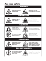
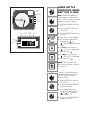
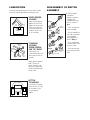
For your safety
DANGER
Keep clear of pressure
relief discharge.
Keep hands away from
moving parts and pinch points.
IMPORTANT
Do not fill kettle above
recommended level
marked on outside of kettle.
Inspect unit daily for
proper operation.
CAUTION
Surfaces may be
extremely hot! Use
protective equipment.
Wear protective equipment
when discharging hot product.
Do not lean on or place
objects on kettle lip.
Stand clear of product
discharge path when
discharging hot product.
SERVICING
Shut off power at main
fuse disconnect prior
to servicing.
0
Ensure kettle is at room
temperature and pressure
gauge is showing zero or less
prior to removing any fittings.
GAS APPLIANCES
Do not attempt to operate
this appliance during a
power failure.
Keep appliance and area free
and clear of combustibles.
INSTALLATION
GENERAL
Installation of the kettle must be accomplished by
qualified installation personnel working to all applicable
local and national codes. Improper installation of
product could cause injury or damage.
This unit is built to comply with applicable standards for
manufacturers. Included among those approval
agencies are: UL, NSF, ASME/Ntl.Bd., CSA, ETL, CE,
and others. Many local codes exist, and it is the
responsibility of the owner/installer to comply with these
codes.
INSPECTION
Before uncrating, visually inspect the unit for evidence
of damage during shipping. If damage is noticed, do
not unpack the unit, follow shipping damage
instructions.
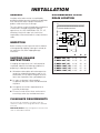
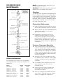
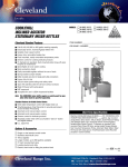
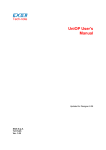
RECOMMENDED FLOOR
DRAIN LOCATION
WALL
18" CLEARANCE REQUIRED FOR SERVICE
DRAW-OFF
VALVE
A
6"
12"
B
12"
C
A
SHIPPING DAMAGE
INSTRUCTIONS
If shipping damage to the unit is discovered or
suspected, observe the following guidelines in
preparing a shipping damage claim.
1. Write down a description of the damage or the
reason for suspecting damage as soon as it is
discovered. This will help in filling out the claim
forms later. If possible, take a polaroid picture.
2. As soon as damage is discovered or
suspected, notify the carrier that delivered the
shipment.
3. Arrange for the carrier's representative to
examine the damage.
4. Fill out all carrier claims forms and have the
examining carrier sign and date each form.
CLEARANCE REQUIREMENTS
This unit must be installed in accordance with the
clearances shown on the rating label which is adhered
to the unit.
FOR YOUR SAFETY. Keep the appliance area free and
clear of combustible materials.
(T) MKDL-40-T(-CC)
(T) MKDL-60-T(-CC)
(T) MKDL-80-T(-CC)
(T) MKDL-100-T(-CC)
(T) MKDL-125-T(-CC)
(T) MKDL-150-T(-CC)
Recommended Floor Drain Location
22
22
22
21
21
21
1/8"
1/8"
1/8"
3/4"
3/4"
3/4"
B
C
51"
53"
58"
61"
65"
68"
31"
31"
31"
31"
31"
31"
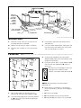
Shim as
required
to make
level with
center
console
(front
and back)
Jack
4"x4" or larger
(front and back)
Skid
Forklift tongs
Flanged feet
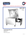
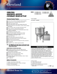
Recommended Installation Procedure
MOVING UNIT
1. While still on skid, move unit as close to final
installation position as possible.
4. Lower gently to ground and remove forklift
and blocking.
2. Prepare unit for lifting as shown in diagram.
5.
3. Lift gently with a forklift or jacks and remove
skid.
If unit has to be re-positioned, slide gently. Do
not twist or push one side of unit excessively
and cause binding on trunnions.
Note: Instructions reflect a more complicated twin mixer kettle - process for single mixer kettles is the same.
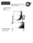
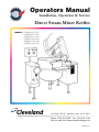
LEVELING
B
A
B
A
3. Level consoles individually from front to back
(dotted lines C). Adjustments are made by turning
flanges on front feet only.
4. Re-check that the back is level (dotted line B)
and then the front (dotted line D). Adjust if
necessary.
C
C
C
5. Check that mixer bridge is level and
guide pins lock smoothly without
binding. If not repeat steps 1 through 4.
C
C
C
D
D
Guide Pins
NOTE: See Operating Instructions before
operating unit.
Recommended Leveling Procedure
6. Make electrical connections (see electrical
service connections) and test mixer bridge as
follows:
1. With straight-edge, line the backs of the
consoles up with each other (dotted line A).
⇒ A/ Raise mixer bridge.
2. Level and straight-edge backs of consoles (dotted
line B). Adjustments are made by turning flanges
on back feet only.
⇒ C/ Swing bridge to the left as far as possible.
⇒ B/ Swing bridge out over centre console.
⇒ D/ Lower bridge.
COMPRESSED AIR CONNECTION
⇒ E/ Bridge pins should enter pin hole on kettle
perfectly, If not return to step 1 and repeat
leveling steps.
Mixer Kettles with an air activated discharge valve
require a minimum of 90 PSI to operate correctly.
⇒ F/ Raise bridge and swing to far right (for twin
mixers only).
If the unit is also supplying air to a Metering Filling
Station then a pressure of 100 PSI at a minimum volume
of 25 CFM is required.
⇒ G/ Repeat steps D and E (for twin mixers
only).
7.
Once positioned and leveled, permanently
secure the kettle's flanged feet to the floor
using 5/16 inch stainless steel lag bolts and
floor anchors (supplied by the installer).
Secure each of the flanged feet with one bolt
in each hole.
8.
Connect piping as described in the "PIPING
CONNECTION" section.
The air supplied to the mixer should be clean and dry.
No oil should be added to the supply air. We
recommend the compressed air system be equipped
with a drier, filter, and automatic water dump on the air
compressor receiver tank. If the distance between the
tank and the unit is less than 100 feet then a minimum
line size of 3/4" is required. A distance of 100 to 300 feet
requires a minimum 1" line.
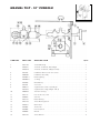
PIPING CONNECTIONS
ELECTRICAL SERVICE
CONNECTIONS
Install in accordance with local codes and/or the
National Electric Code ANSI/NFPA No 70-1981 (USA)
or the Canadian Electric Code CSA Standard C22.1
(Canada). A separate fused disconnect switch must
be supplied and installed. The kettle must be
electrically grounded by the installer.
The electric supply must match the power
requirements specified on the kettle's rating plate.
The copper wiring must be adequate to carry the
required current at the rated voltage. Refer to the
specification sheet for electrical specifications.
1. Ensure main power is turned off before
connecting wires.
2. Remove the screws at the rear of the center
console cover, and remove the cover. A wiring
diagram is affixed to the underside of the
console cover.
3. Feed permanent copper wiring 18" through the
cut-out in the bottom of the console. Connect
wiring in junction box in the bottom of the
console.
4. Turn main power back on.
5. Check for correct rotation of electric motor
(access by removing top front cover on center
console). If rotation is incorrect, disconnect
main power and reverse any two of the three
live lines.
6. Replace the console cover and secure it with
screws.
1. All plumbing to and from the kettle should be
thoroughly cleaned and inspected for dirt and
debris before the final connections to the kettle
are made.
2. Connect all piping according to identification
tags on unit.
3. Piping between boiler and kettle should be
sloped and a drip condensate trap installed at
lowest point.
4. Insulating steam piping is recommended for
safety and higher efficiency.
5. To determine the correct steam supply pipe
size:
⇒ A/ Find the total steam requirement using the
first chart.
⇒ B/ Use the steam requirement total in the second
chart to find the correct pipe size.
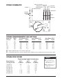
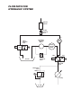
DUMP VALVE TO DRAIN
PIPING SCHEMATIC
CONDENSATE OUT
STEAM IN
HOT WATER
COOLING WATER IN
COLD WATER
COOLING WATER OUT
GLOBE VALVES
PRESSURE
REDUCING
VAVLE
PVR
UNIONS
STRAINERS
STEAM REQUIREMENTS FOR KETTLES
Kettle Cap.
U.S. Gal.
Kettle
Dia.
40
60
80
100
125
150
26"
29.5"
33"
36"
40"
40"
25 psi Steam 265°F
Lbs./Hr.
Hp./Hr.
100
150
210
260
320
390
3
4.5
6.0
7.5
9.5
11.0
40 psi Steam 287°F
Lbs./Hr.
Hp./Hr.
120
190
260
320
400
480
4
5.5
7.5
9.5
11.5
14.0
80 psi Steam 302°F
Lbs./Hr.
Hp./Hr.
150
230
300
390
470
570
4.5
7.0
9.0
11.0
14.0
17.0
Steam requirements are maximum per hour.
If more than one unit is on the same line then add the steam usage for each one to reach a total.
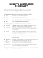
STEAM PIPE SIZING
NOTES:
Required pipe length in feet/meters
Steam Required
Lbs./Kg. per hour
100/45 Kg.
200/91 Kg.
300/136 Kg.
400/182 Kg.
500/227 Kg.
700/318 Kg.
900/409 Kg.
200 Ft.
60 Meters
3/4"
1"
1"
1"
1 1/4"
1 1/2"
1 1/2"
400 Ft.
125 Meters
1
1
1
1
1
1
1"
1/4"
1/4"
1/2"
1/2"
3/4"
3/4"
600 Ft.
185 Meters
1
1
1
1
1
1/4"
1/2"
1/2"
3/4"
3/4"
2"
2"
Pipe size in inches.
Less than 50 PSI (3.4
BAR) pressure, increase
pipe size by 1/4".
80 to 100 PSI (5.5 to 6.8
BAR), Decrease pipe
size by 1/4".
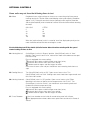
QUALITY ASSURANCE
CHECKLIST
Follow this list only after all other installation steps are completed.
Some steps require the use of equipment. Follow operating instructions.
The following will be performed before the unit is connected to utilities:
1. Visual
Examine unit for scratches, dents, or other defects.
2. Visual
Check flanged feet all have bolts holding them.
3. General
Check all accessible wiring, mechanical and plumbing connections by hand for
secure, tight and satisfactory assembly. Remove all paper.
4. Level
Check unit has been leveled and squared correctly.
The following will be performed with the unit connected to utilities:
5. Raise Bridge
If bridge does not raise then check motor rotation. Bridge should not raise until
speed control is turned to minimum and then adjusted back up.
6. Swing Bridge
Bridge when fully raised should swing without hitting any object, i.e. control
housing, kettle lip. Check that hydraulic hoses are not being pinched by stops
on swivel assembly.
7.
Kettle tilts smoothly both down and back up. If power tilt, check that micro
switches are adjusted properly (kettle is level in upright position and drains fully
when tilted) and are not being crushed by gear.
Tilt Kettle
8. Lower Bridge
Raise bridge. Switch to mix. Turn speed control to zero to reset micro switch then
set speed control to number four. Check that unit does not begin to mix until
bridge has lowered part way into the kettle. Check that mixer bridge pin lowers
into pin hole correctly
9. Speed Control Main
Main agitator arm not rotating when set at minimum but will start to move slowly on
one. Speed control makes positive contact with micro switch.
10. Speed Control Secondary
Set main speed control to five. Adjust secondary control from
minimum to maximum. Look for considerable speed variance.
11. Water Faucets
Turn on hot water faucet. Turn off and check for leaks in piping and drips from
faucet spout. Repeat above with cold water faucet.
12. Product Discharge Add water to kettle. Check for leaks from valve. Open and close valve a few times
Valve
and check for leaks again.
OPTIONAL CONTROLS
Some units may not have the following items to test
13. Meter
Complete this test using markings on mixer arm or a measuring strip if there are no
markings on the unit. Test the meter at the following values up to capacity (Should be
approx. ±1/4"). During this test check that the (interrupt) switch stops the water flow
and the (continue/reset) when switched to "continue" resumes the flow without resetting
the meter.
GALLONS
5
20
40
80
100
LITERS
20
80
160
320
400
When the (continue/reset) switch is turned to "reset" the displayed quantity on the
meter should be erased and the count begins at zero.
For the following test fill the kettle 3/4 full of water. Have the mixer rotating with the speed
control setting at three to five.
14. Heating Manual
(Active/Bypass) switch in "Bypass" position. (Heat/Off/Cool) switch in "Heat"
position. Open manual steam valve, steam enters kettle and condensate escapes
from steam trap.
For units equipped with water cooling 1./ Automatic drain opens and discharges water from jacket,
2./ Automatic drain closes when steam starts exiting,
3./ Condensate drain opens and discharges hot water.
Close manual steam valve and you should hear steam entering kettle slow to a
stop.
15. Cooling Manual
Turn (Heat/Off/Cool) switch to "Off". Open manual steam valve. Turn
(Heat/Off/Cool) switch to "Cool". Cooling water enters kettle from large console and
exits from side console.
16. Heating Automatic (Heat/Off/Cool) switch in "Off" position. Open manual steam valve. Follow
operating instructions on label to set the temperature to 180°F/ 90°C. Turn
(Active/Bypass) switch to "Active", you should hear steam entering kettle and
condensate should escape steam trap.
For units equipped with water cooling 1./ Automatic drain opens and discharges water from jacket,
2./ Automatic drain closes when steam starts exiting,
3./ Condensate drain opens and discharges hot water.
17 Chart Recorder
a) Seal chart recorder on the inside all around to the panel with silicone.
b) Seal pipe penetration where cables enters panel from console with silicone all
around.
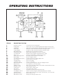
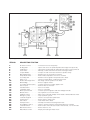
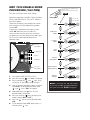
OPERATING INSTRUCTIONS
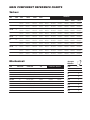
Operating Controls & Indicators for Standard Direct Steam Mixer Kettles
ITEM NO.
DESCRIPTION FUNCTION
1.
2.
3.
4.
5.
6.
7.
8.
9.
10.
11.
12.
13.
14.
15.
16.
17.
18.
19.
20.
21.
22.
23.
24.
25.
26.
Air Quick Connect . . . . . . . . . .Connection for air to food pump.
Air Regulator . . . . . . . . . . . . . .Opens and closes air operated product discharge valve (Item 10).
Hand Wheel . . . . . . . . . . . . . .Tilts kettle for pouring. May be replaced by tilt switch if unit is power tilt.
Steam Valve . . . . . . . . . . . . . .Manually controls the amount of steam entering the kettle.
Scraper Blades . . . . . . . . . . . .Scrapes the side of the kettle and moves product away.
Main Agitator Arm . . . . . . . . . .Provides most of the product movement.
Temperature Probe . . . . . . . . .Probe holds temperature sensors for controller.
Secondary Arm . . . . . . . . . . . .Provides reverse agitation and product lift in kettle.
Drain Cock . . . . . . . . . . . . . . .Used to manually drain condensate from kettle.
Product Discharge Valve . . . .Discharge valve for product in the kettle.
Mixer Bridge . . . . . . . . . . . . . .Encloses agitator motors.
Secondary Speed Control . . .Controls speed of secondary agitator arm.
Faucet Spout . . . . . . . . . . . . . .Delivers water to the kettle.
Hot Water Valve . . . . . . . . . . . .Turns on hot water.
Cold Water Valve . . . . . . . . . . .Turns on cold water.
Mixer Speed Control . . . . . . . .Controls speed of agitators and mixer bridge lift mode.
Mix/Lift Switch . . . . . . . . . . . . .Sets hydraulics to mix or lift mode.
Up/Down Switch . . . . . . . . . . .When unit is in lift mode, bridge can be raised or lowered with this switch.
Emergency Stop . . . . . . . . . . .Stops hydraulic system.
On/Off Switch . . . . . . . . . . . . .Power switch to water meter.
Start Switch . . . . . . . . . . . . . . .Starts water flow to kettle.
Interrupt Switch . . . . . . . . . . . .Interrupts flow without resetting water meter.
Active/Bypass Switch . . . . . . .Switch to activate or bypass (manual operation) the controller.
Controller Switch . . . . . . . . . . .Dual function switch for auto mode or manual heat, cool or off mode.
Main Power Switch . . . . . . . . .Power switch for unit.
Water Meter Control . . . . . . . .Display and setting for water meter.
Operating Controls & Indicators for Cook Chill Direct Steam Mixer Kettles
ITEM NO.
DESCRIPTION FUNCTION
1.
2.
3.
4.
5.
6.
7.
8.
9.
10.
11.
12.
13.
14.
15.
16.
17.
18.
19.
20.
21.
22.
23.
24.
25.
26.
27.
Air Quick Connect . . . . . . . . . .Connection for air to food pump.
Air Regulator . . . . . . . . . . . . . .Opens and closes air operated product discharge valve (Item 10).
Hand Wheel . . . . . . . . . . . . . .Tilts kettle for pouring. May be replaced by tilt switch if unit is power tilt.
Steam Valve . . . . . . . . . . . . . .Manually controls the amount of steam entering the kettle.
Scraper Blades . . . . . . . . . . . .Scrapes the side of the kettle and moves product away.
Main Agitator Arm . . . . . . . . . .Provides most of the product movement.
Temperature Probe . . . . . . . . .Probe holds temperature sensors for controller.
Secondary Arm . . . . . . . . . . . .Provides reverse agitation and product lift in kettle.
Drain Cock . . . . . . . . . . . . . . .Used to manually drain condensate from kettle.
Product Discharge Valve . . . .Discharge valve for product in the kettle.
Mixer Bridge . . . . . . . . . . . . . .Encloses agitator motors.
Secondary Speed Control . . .Controls speed of secondary agitator arm.
Faucet Spout . . . . . . . . . . . . . .Delivers water to the kettle.
Hot Water Valve . . . . . . . . . . . .Turns on hot water.
Cold Water Valve . . . . . . . . . . .Turns on cold water.
Mixer Speed Control . . . . . . . .Controls speed of agitators and mixer bridge lift mode.
Mix/Lift Switch . . . . . . . . . . . . .Sets hydraulics to mix or lift mode.
Up/Down Switch . . . . . . . . . . .When unit is in lift mode, bridge can be raised or lowered with this switch.
Emergency Stop . . . . . . . . . . .Stops hydraulic system.
Controller Keypad . . . . . . . . . .Used to set temperature parameters.
On/Off Switch . . . . . . . . . . . . .Power switch to water meter.
Start Switch . . . . . . . . . . . . . . .Starts water flow to kettle.
Interrupt Switch . . . . . . . . . . . .Interrupts flow without resetting water meter.
Active/Bypass Switch . . . . . . .Switch to activate or bypass (manual operation) the controller.
Controller Switch . . . . . . . . . . .Dual function switch for auto mode or manual heat, cool or off mode.
Main Power Switch . . . . . . . . .Power switch for unit.
Water Meter Control . . . . . . . .Display and setting for water meter.
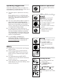
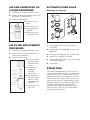
Operating Suggestions
OFF
ON
General Operation
1. Turn MAIN POWER SWITCH
to "ON".
Cleveland Range Mixer Kettles are simple and
safe to operate. The following tips will allow you to
maximize the use of your new mixer.
1. To achieve optimum performance on tilting
kettles;
Before applying steam to a cold kettle, open
the DRAIN COCK to drain condensate from the
kettles jacket. Close drain cock when unit is
fully drained.
2. Allow unit to preheat before addition of product to
kettle. However when cooking egg and milk
products, the kettle should NOT be preheated, as
products of this nature adhere to hot cooking
surfaces. These types of foods should be placed
in the kettle before heating is begun.
OFF
MIX
LIFT
WARNING- Insure FAUCET
SPOUT is out of way before
raising or lowering bridge.
1. Turn MIX/LIFT SWITCH to "LIFT".
UP
OFF
DOWN
3. An important part of kettle cleaning is to
prevent foods from drying on. For this reason,
cleaning should be completed immediately
after cooked foods are removed. Refer to the
"Care and Cleaning" instructions for detailed
kettle washing procedures.
4. If a mixer bridge is equipped with a
temperature probe for a controller or
thermometer, the probe must be submerged a
minimum of three inches in the product for
accurate readings.
Safety
1. Close PRODUCT DISCHARGE VALVE before
filling the kettle.
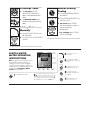
Lifting & Lowering
Bridge
OFF
MIX
LIFT
2. Turn MIXER SPEED
CONTROL to "MIN" and back
up to #5.
3. Turn and hold UP/DOWN
SWITCH "UP" to raise or
"DOWN" to lower.
Mixing
1. Turn MIX/LIFT SWITCH to "MIX".
2. Turn MIXER SPEED
CONTROL to "MIN" and
slowly adjust to desired
speed.
3. Adjust SECONDARY SPEED
CONTROL to desired speed.
2. When raising or lowering MIXER BRIDGE,
insure FAUCET SPOUT is not in the way of
MAIN AGITATOR ARM or damage to spout
will result.
3. As a safety precaution the MIXER SPEED
CONTROL must first be turned to zero before
unit will start to mix.
4. Always remember, like a cooking pot the
kettles become very hot when cooking. Avoid
contact with bare skin.
Tilting Kettle
1. Raise MIXER BRIDGE and
swing to side.
2. For manual tilt: turn
HANDWHEEL.
3. For power tilt: turn switch
"
" to raise, or "
" to tilt.
WARNING- Do not tilt kettle
when mixer agitators are in kettle
bowl.
Discharge Valve
BYPASS ACTIVE
1. For air valve: turn AIR
REGULATOR clockwise to
open, or counterclockwise to
close.
Manual Heating/
Cooling
1. Turn ACTIVE/BYPASS SWITCH
to "BYPASS".
OFF
HEAT AUTO COOL
2. For butterfly valve: push
handle in and pull upwards to
open.
2. Turn CONTROLLER SWITCH to
"HEAT" or "COOL".
3. For heat: open STEAM
VALVE completely to boil, or
adjust to regulate
temperature.
Adding Water
Manually
For cooling: open STEAM
VALVE completely.
1. Locate FAUCET SPOUT over
desired kettle.
2. Turn on HOT or COLD WATER
VALVES.
Upper
Display
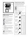
DIGITAL WATER
METER OPERATING
INSTRUCTIONS
3
2000
Lower
Display
1930
Note: The digital counter has been preset at the
factory and should operate satisfactory. If
installing a new counter (or the configuration
settings to your existing digital counter become
corrupted) you must configure the digital counter
as shown below (Configuring a Digital
Counter) prior to operation.
PST
OUT
PGM
ENT
CONTINUE RESET
Program
Indicator
ON
1
Turn POWER switch "ON".
Turn START switch to "RESET".
Delivery will start at "0" and stop at
preset volume.
INTERRUPT
RST
Next
Key
Enter
Key
To stop delivery at any time, turn
INTERRUPT switch to " ".
Reset
Key
CONTINUE RESET
OFF
4
5
Down
Key
Locate delivery spout over
desired kettle.
2
Set required volume by first pushing the
key until the digit you want to change is
flashing in the lower display. Then use the
key to change the value of the selected digit.
When all digits are set, press the ENT key.
OFF
6
To complete delivery after
interrupting, turn START switch
to "CONTINUE"
ON
7
Turn POWER switch to "OFF"
when meter is not in use.
Changing Functions & Options
CAL 9900
Hi
˚C
Process
Temperature
or Set Point
Sp
Lo
The controller has been preset at the factory and should
operate satisfactory. If you wish to fine tune the unit for
your specific application consult the CAL 990O
Installation and Operation Manual. Following is a
simplified procedure for changing parameters.
SP1
Error
OFF
ON
1. Mixer MAIN POWER switch in the "ON"
position.
SP2
BYPASS ACTIVE
*
*
*
*
p
View Set Point
Decrease
Increase
CAL 9900 Controls Drawing
MIXER KETTLE OPERATION
USING CAL 9900
Note: Temperature probe on mixer bridge must
be covered with a minimum of three inches of
product to function correctly.
2. ACTIVE/BYPASS switch in "BYPASS" position.
3. Press button labeled (p). The display should show a
number with a decimal place in it.
Left of the decimal
place is the
OPERATING MODE
setting (this number
should be flashing).
To the right is the
FUNCTION NUMBER.
4. To change the
OPERATING MODE
setting push the
(
) or (
)
buttons.
CAL 9900
*
p
CAL 9900
*
˚C
˚C
p
1. Open STEAM VALVE completely
OFF
ON
OFF
HEAT AUTO COOL
BYPASS ACTIVE
2. Turn mixer MAIN POWER switch to
"ON" (CAL 9900 lights up and
displays present temperatures).
3. Turn HEAT/COOL switch to
“OFF/AUTO".
4. Turn ACTIVE/BYPASS switch to
"BYPASS". The unit should not be
heating or cooling at this point.
5. Push ( ) button on CAL 9900 to read set point
temperature. (This is the desired product
temperature).
*
6. To change set point temperature push and
hold ( ) button while pushing ( ) or ( )
button. New set point is determined when
( ) button is released.
*
*
7. Add product to kettle.
8. Turn ACTIVE/BYPASS switch to
“ACTIVE”. If the set point
temperature is higher than the
product temperature, the kettle will start heating.
5. To move to the
FUNCTION NUMBER
(right of the
decimal) push
( ) button.
*
6. That number
should now be
flashing. To move
to another FUNCTION
NUMBER push the
( ) or ( )
buttons.
*
7. Push ( ) button to
move to the left of the
decimal. To change
the OPERATING MODE
setting push the
( ) or ( )
buttons.
CAL 9900
*
p
CAL 9900
*
˚C
p
CAL 9900
*
˚C
˚C
p
BYPASS ACTIVE
Note: For twin kettles, the CAL 9900 will control
the kettle the mixer is in.
8. When your changes
are complete push
the button labeled
(p) again to return
to the Process
Temperature.
CAL 9900
*
p
˚C
Cleveland
Range
Factory
Settings
OPERATING FUNCTION
MODE
NUMBER
0
0
0
1
5
2
0
3
4 steam
4
5 electric
0
5
5
6
0
7
0
8
1
9
0
10
0
11
0
12
0
13
0
14
0
15
9
16
17
0
0
18
1
19
2 T.A.P
20
0
0
21
0 = °C
22
1 = °F
6
23
-- -24
0
25
-- -26
OFF
MAN
ON
Pen
Display
OUT1 OUT2 ALRM
SP
˚C
˚F
U
Pen1 key AUTO/MAN
SCROLL Key
AUTO
MAN
OFF
HEAT AUTO COOL
UP Key
DOWN Key
BYPASS ACTIVE
MIXER KETTLE
OPERATION USING
MRC 7000 (1 PEN)
Note: Temperature probe on
mixer bridge must be covered
with a minimum of three inches of
product to function correctly.
1. Turn MAIN POWER switch to
"ON".
2. Turn HEAT/COOL switch to
"OFF/AUTO".
Manual
MAN
Setpoint
Heat
Cooling
Output 1 Output 2
3. Turn ACTIVE/BYPASS switch to
"ACTIVE".
Alarm
4. Open steam valve completely.
OUT1 OUT2 ALRM
5. On controller keypad push
and hold key " " or
" " until desired temperature
is set.
SP
Minus Sign
˚C
˚F
˚U
6. To start: push scroll key
"
" until "CtrL" is displayed.
7. Push down key "
MRC 7000 Controls Drawing (1 pen)
".
8. To stop: push scroll key
"
" until "OFF " is displayed.
9. Push down key "
".
NOTE: For twin kettles, the
MRC 7000 will control the kettle
the mixer is in.
OFF
HEAT AUTO COOL
BYPASS ACTIVE
If the unit is used continually it
may be simpler to control the
"ON/OFF " function with the
following steps:
1. Keep HEAT/COOL switch at
"OFF/AUTO".
2. To stop turn ACTIVE/BYPASS
switch to "BYPASS".
BYPASS ACTIVE
3. To change temperature
setting push and hold key
" " or " " until desired
temperature is set.
4. To start, turn ACTIVE/BYPASS
switch to "ACTIVE".
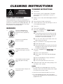
CLEANING INSTRUCTIONS
CAUTION
SURFACES MAY
BE EXTREMELY HOT!
CARE AND CLEANING
Cooking equipment must be cleaned regularly to
maintain its fast, efficient cooking performance and
to ensure its continued safe, reliable operation. The
best time to clean is shortly after each use (allow
unit to cool to a safe temperature).
CLEANING INSTRUCTIONS
1. Turn unit off.
2. Remove drain screen (if applicable). Thoroughly
wash and rinse the screen either in a sink or a
dishwasher.
3. Prepare a warm water and mild detergent solution in
the unit.
4. Remove food soil using a nylon brush.
5. Loosen food which is stuck by allowing it to soak at
a low temperature setting.
6. Drain unit.
WARNINGS
➩
7. Rinse interior thoroughly.
Do not use detergents or
cleansers that are chloride
based or contain quaternary
salt.
Chloride Cleaners
➩
Do not use a metal bristle
brush or scraper.
8. If the unit is equipped with a Tangent Draw-Off
Valve, clean as follows:
a) Disassemble the draw-off valve first by turning
the valve knob counter-clockwise, then turning
the large hex nut counter-clockwise until the
valve stem is free of the valve body.
b) In a sink, wash and rinse the inside of the valve
body using a nylon brush.
c) Use a nylon brush to clean tangent draw-off tube.
d) Rinse with fresh water.
e) Reassemble the draw-off valve by reversing the
procedure for disassembly. The valve's hex nut
should be hand tight only.
Wire Brush &
➩
Steel wool should never be
used for cleaning the stainless
steel.
9. If the unit is equipped with a Butterfly Valve, clean
as follows:
a) Place valve in open position.
b) Wash using a warm water and mild detergent
solution.
Steel Pads
c) Remove food deposits using a nylon brush.
➩
Unit should never be cleaned
with a high pressure spray
hose.
d) Rinse with fresh water.
e) Leave valve open when unit is not in use.
10. Using mild soapy water and a damp sponge, wash
the exterior, rinse, and dry.
NOTES
High Pressure
Spray Hose
➩
Do not leave water sitting in unit
when not in use.
➩ For more difficult cleaning applications one of the
following can be used: alcohol, baking soda, vinegar,
or a solution of ammonia in water.
➩ Leave the cover off when the kettle is not in use.
Stagnant
Water
➩ For more detailed instructions refer to the Nafem
Stainless Steel Equipment Care and Cleaning manual
(supplied with unit).
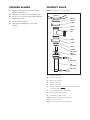
SCRAPER BLADES
PRODUCT VALVE
1. Remove retaining ring and slide scraper
blades off agitator arm.
Daily - clean product valve as follows:
2. Place parts in a pan of warm water to soak.
KETTLE
3. Clean in a sink, using a warm water and mild
detergent solution.
KETTLE
OUTLET
4. Rinse with fresh water.
CLAMP
5. Allow to dry thoroughly on a flat, clean
surface.
0-RING
VALVE
TEE
0-RING
CLAMP
0-RING
CLOSED
POSTITION
OPEN
POSITION
AIR HOSE
AIR
CYLINDER
AIR HOSE
1.
Open product valve.
2.
Disconnect air hoses.
3.
Remove air cylinder.
4.
Remove valve tee.
5.
Remove all O-rings.
6.
Clean air cylinder, do not submerge in water. Wipe
clean and sanitize.
7.
Clean and sanitize tee and O-rings.
8.
Grease and reinstall O-rings.
9.
Reinstall tee to kettle outlet.
10. Reinstall air cylinder to bottom of tee.
11. Reconnect air hoses.
12. Close valve and check for alignment.
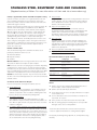
STAINLESS STEEL EQUIPMENT CARE AND CLEANING
(Suppied courtesy of Nafem. For more information visit their web site at www.nafem.org)
Contrary to popular belief, stainless steels ARE susceptible to rusting.
4. Treat your water.
Though this is not always practical, softening hard water can do much
to reduce deposits. There are certain filters that can be installed to
remove distasteful and corrosive elements. To insure proper water
treatment, call a treatment specialist.
Corrosion on metals is everywhere. It is recognized quickly on iron and
steel as unsightly yellow/orange rust. Such metals are called “active”
because they actively corrode in a natural environment when their atoms
combine with oxygen to form rust.
Stainless steels are passive metals because they contain other metals, like
chromium, nickel and manganese that stabilize the atoms. 400 series
stainless steels are called ferritic, contain chromium, and are magnetic;
300 series stainless steels are called austenitic, contain chromium and
nickel; and 200 series stainless, also austenitic, contains manganese,
nitrogen and carbon. Austenitic types of stainless are not magnetic, and
generally provide greater resistance to corrosion than ferritic types.
With 12-30 percent chromium, an invisible passive film covers the steel’s
surface acting as a shield against corrosion. As long as the film is intact
and not broken or contaminated, the metal is passive and stain-less. If the
passive film of stainless steel has been broken, equipment starts to
corrode. At its end, it rusts.
5. Keep your food equipment clean.
Use alkaline, alkaline chlorinated or non-chloride cleaners at
recommended strength. Clean frequently to avoid build-up of hard,
stubborn stains. If you boil water in stainless steel equipment,
remember the single most likely cause of damage is chlorides in the
water. Heating cleaners that contain chlorides have a similar effect.
6. Rinse, rinse, rinse.
If chlorinated cleaners are used, rinse and wipe equipment and
supplies dry immediately. The sooner you wipe off standing water,
especially when it contains cleaning agents, the better. After wiping
equipment down, allow it to air dry; oxygen helps maintain the
stainless steel’s passivity film.
Enemies of Stainless Steel
There are three basic things which can break down stainless steel’s
passivity layer and allow corrosion to occur.
7. Never use hydrochloric acid (muriatic acid) on stainless steel.
8. Regularly restore/passivate stainless steel.
1. Mechanical abrasion
2. Deposits and water
Recommended cleaners for specific situations
3. Chlorides
Job
Cleaning Agent
Comments
Mechanical abrasion means those things that will scratch a steel surface.
Steel pads, wire brushes and scrapers are prime examples.
Routine cleaning
Soap, ammonia,
detergent, Medallion
Apply with cloth or sponge
Fingerprints & smears
Arcal 20, Lac-O-Nu
Ecoshine
Provides barrier film
Stubborn stains &
discoloration
Cameo, Talc, Zud,
First Impression
Rub in direction of polish lines
Grease & fatty acids,
blood, burnt-on-foods
Easy-off, De-Grease
It Oven Aid
Excellent removal on all finishes
Grease & oil
Any good
commercial detergent
Apply with sponge or cloth
Restoration/Passivation
Benefit, Super Sheen
Water comes out of the faucet in varying degrees of hardness. Depending
on what part of the country you live in, you may have hard or soft water.
Hard water may leave spots, and when heated leave deposits behind that
if left to sit, will break down the passive layer and rust stainless steel. Other
deposits from food preparation and service must be properly removed.
Chlorides are found nearly everywhere. They are in water, food and table
salt. One of the worst chloride perpetrators can come from household and
industrial cleaners.
So what does all this mean? Don’t Despair!
Here are a few steps that can help prevent stainless steel rust.
1. Use the proper tools.
When cleaning stainless steel products, use non-abrasive tools. Soft
cloths and plastic scouring pads will not harm steel’s passive layer.
Stainless steel pads also can be used but the scrubbing motion must
be in the direction of the manufacturers’ polishing marks.
2. Clean with the polish lines.
Some stainless steel comes with visible polishing lines or “grain.”
When visible lines are present, always scrub in a motion parallel to the
lines. When the grain cannot be seen, play it safe and use a soft cloth
or plastic scouring pad.
Review
1. Stainless steels rust when passivity (film-shield) breaks down as a
result of scrapes, scratches, deposits and chlorides.
2. Stainless steel rust starts with pits and cracks.
3. Use the proper tools. Do not use steel pads, wire brushes or scrapers
to clean stainless steel.
4. Use non-chlorinated cleaners at recommended concentrations. Use
only chloride- free cleaners.
5. Soften your water. Use filters and softeners whenever possible.
6. Wipe off cleaning agent(s) and standing water as soon as possible.
Prolonged contact causes eventual problems.
3. Use alkaline, alkaline chlorinated or non-chloride containing cleaners.
While many traditional cleaners are loaded with chlorides, the industry
is providing an ever-increasing choice of non-chloride cleaners. If you
are not sure of chloride content in the cleaner used, contact your cleaner
supplier. If your present cleaner contains chlorides, ask your supplier if
they have an alternative. Avoid cleaners containing quaternary salts; it
also can attack stainless steel and cause pitting and rusting.
To learn more about chloride-stress corrosion and how to prevent it,
contact the equipment manufacturer or cleaning materials supplier.
Developed by Packer Engineering, Naperville, Ill., an independent testing
laboratory.
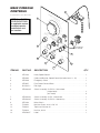
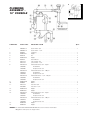
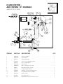
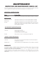
SERVICE PARTS
WARRANTY
Our Company supports a worldwide network of
Maintenance and Repair Centers. Contact your
nearest Maintenance and Repair Centre for
replacement parts, service, or information
regarding the proper maintenance and repair of
your cooking equipment
In order to preserve the various agency safety
certification (UL, NSF, ASME/Ntl. Bd., etc.), only
factory-supplied replacement parts should be
used. The use of other than factory supplied
replacement parts will void warranty.
1
51
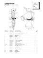
HYDRAULIC
COMPONENTS
7
6
Scraper
Blades:
8
5
9
41
47
KETTLE
SIZE
GALLONS
10
QUANTITY
40
22
60
26
80
30
100
34
125
38
150
38
46
52
39 40
4
3
11
43
12
38
2
37
1
44
36
13A
48
13B
14
15
35
42
34
50
49
16
30
18
32
19
Cooling Fan:
20
Fan . . . . . . . . KE54860
Fan Cover . . . KE601236
Fan Guard . . . KE54861
31
29
21 22 23
33
28
27
24
25
26
NOTE: For Hydraulic Hoses order
Part No. RT00505 and specify
length required
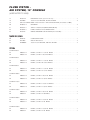
ITEM NO.
PART NO.
DESCRIPTION
1.
2.
KE51607
KE54834-10
SE50224
KE51608
KE54834-11
SE50224
KE51848
SE50241
SE50242
KE52124
KE51846
KE51938
KE53004
FA95006
KE51845
KE53005
KE51715
KE51716
KE52114
FA11286
FA11346
KE52115
CT50097
KE53962
Flow Control Valve . . . . . . . . . . . . . . . . . . . . . . . . . . . . . . . . . . . . . . . . . . . . . . . . . . . . . . . .2
Solenoid Valve, 2 Way, 120 Volt . . . . . . . . . . . . . . . . . . . . . . . . . . . . . . . . . . . . . . . . . . . . .1
Coil Only 120 Volt . . . . . . . . . . . . . . . . . . . . . . . . . . . . . . . . . . . . . . . . . . . . . . . . . . . . . . . .1
Check Valve . . . . . . . . . . . . . . . . . . . . . . . . . . . . . . . . . . . . . . . . . . . . . . . . . . . . . . . . . . . .1
Solenoid Valve, 3 Way, 120 Volt . . . . . . . . . . . . . . . . . . . . . . . . . . . . . . . . . . . . . . . . . . . . .1
Coil Only 120 Volt . . . . . . . . . . . . . . . . . . . . . . . . . . . . . . . . . . . . . . . . . . . . . . . . . . . . . . . .1
Jack . . . . . . . . . . . . . . . . . . . . . . . . . . . . . . . . . . . . . . . . . . . . . . . . . . . . . . . . . . . . . . . . . . .1
Rod Gland Seal Kit . . . . . . . . . . . . . . . . . . . . . . . . . . . . . . . . . . . . . . . . . . . . . . . . . . . . . . .1
Piston Seal Kit. . . . . . . . . . . . . . . . . . . . . . . . . . . . . . . . . . . . . . . . . . . . . . . . . . . . . . . . . . .1
Jack Upper Pin . . . . . . . . . . . . . . . . . . . . . . . . . . . . . . . . . . . . . . . . . . . . . . . . . . . . . . . . . .1
Hydraulic Motor, Scraper Arm, 40 gal. . . . . . . . . . . . . . . . . . . . . . . . . . . . . . . . . . . . . . . .1
Hydraulic Motor, Scraper Arm, 60-150 gal.
Hydraulic Motor, Scraper Arm, 200-250 gal.
Woodruff Key . . . . . . . . . . . . . . . . . . . . . . . . . . . . . . . . . . . . . . . . . . . . . . . . . . . . . . . . . . . .1
Hydraulic Motor, Secondary Agitator, 40-150 gal. . . . . . . . . . . . . . . . . . . . . . . . . . . . . . . .1
Hydraulic Motor, Secondary Agitator, 200-250 gal.
Main Coupling, Scraper Arm . . . . . . . . . . . . . . . . . . . . . . . . . . . . . . . . . . . . . . . . . . . . . . .1
Secondary Coupling, Agitator Arm . . . . . . . . . . . . . . . . . . . . . . . . . . . . . . . . . . . . . . . . . . .1
Coupling Washer, Primary S.S. . . . . . . . . . . . . . . . . . . . . . . . . . . . . . . . . . . . . . . . . . . . . . .1
Socket Head Screw, 1/4 X 20 . . . . . . . . . . . . . . . . . . . . . . . . . . . . . . . . . . . . . . . . . . . . . . .2
Socket Head Screw, 5/16 X 20 . . . . . . . . . . . . . . . . . . . . . . . . . . . . . . . . . . . . . . . . . . . . . .2
Coupling Washer, Secondary S. S. . . . . . . . . . . . . . . . . . . . . . . . . . . . . . . . . . . . . . . . . . . .1
R.T.D Probe Single . . . . . . . . . . . . . . . . . . . . . . . . . . . . . . . . . . . . . . . . . . . . . . . . . . . . . . .1
Blade Stop Ring . . . . . . . . . . . . . . . . . . . . . . . . . . . . . . . . . . . . . . . . . . . . . . . . . . . . . . . . .2
3.
4.
5.
6.
7.
8.
9.
10.
11.
12.
13A.
13B.
14.
15.
16.
QTY.
18.
19.
20.
21.
21.
22.
23.
24.
25.
26.
27.
28.
29.
30.
31.
32.
33.
34.
35.
36.
37.
38.
39.
40.
41.
42.
43.
44.
46.
47.
48.
49.
50.
51.
52.
KE51834
KE51875-3
KE51875-4
KE51875-5
KE51889
KE52222
KE52222-1
KE52223
KE52224
KE52190
KE52171
KE51844
FI05060
SE50280
FI05061
SE50094
KE51874
KE52382
KE00860
KE51622
FA95022
KE51623
SE50353
KE51624
KE50295
KE50294
FA95055-3
T40527
T40528
T40529
T40530
T40531
T40532
T405321
T405322
KE51921
KE51925
FA19506
FA19507
KE00935
KE00936
KE00937
KE00938
KE00939
KE00940
KE009401
KE009402
KE00947
KE00948
KE00949
KE00950
KE00951
KE00952
KE009521
KE009522
KE00947-1
KE00948-1
KE00949-1
KE00950-1
KE00951-1
KE00952-1
KE009521-1
KE009522-1
KE52687
RT00505
KE00715
Scraper Blades . . . . . . . . . . . . . . . . . . . . . . . . . . . . . . . . . . . . . . . . . . . . . . . . .as required
Electric Motor, 3 hp., 208-230/460V . . . . . . . . . . . . . . . . . . . . . . . . . . . . . . . . . . . . . . . . . .1
Electric Motor, 3 hp., 220/380/440V . . . . . . . . . . . . . . . . . . . . . . . . . . . . . . . . . . . . . . . . . .1
Electric Motor, 3 hp., 575V . . . . . . . . . . . . . . . . . . . . . . . . . . . . . . . . . . . . . . . . . . . . . . . . .1
Filter, Tank Breather . . . . . . . . . . . . . . . . . . . . . . . . . . . . . . . . . . . . . . . . . . . . . . . . . . . . . . .1
Gear, 3/4" I.D. Pump, prior to 1995 . . . . . . . . . . . . . . . . . . . . . . . . . . . . . . . . . . . . . . . . . . .1
Gear, 3/4" I.D. Pump, after 1995 . . . . . . . . . . . . . . . . . . . . . . . . . . . . . . . . . . . . . . . . . . . . .1
Gear, 7/8" I.D. Motor . . . . . . . . . . . . . . . . . . . . . . . . . . . . . . . . . . . . . . . . . . . . . . . . . . . . . .1
Nylon Coupling. . . . . . . . . . . . . . . . . . . . . . . . . . . . . . . . . . . . . . . . . . . . . . . . . . . . . . . . . .1
Speed Control Knob . . . . . . . . . . . . . . . . . . . . . . . . . . . . . . . . . . . . . . . . . . . . . . . . . . . . . .1
Gasket, Oil Tank . . . . . . . . . . . . . . . . . . . . . . . . . . . . . . . . . . . . . . . . . . . . . . . . . . . . . . . . .1
Hydraulic Pump . . . . . . . . . . . . . . . . . . . . . . . . . . . . . . . . . . . . . . . . . . . . . . . . . . . . . . . . .1
Swivel adapter . . . . . . . . . . . . . . . . . . . . . . . . . . . . . . . . . . . . . . . . . . . . . . . . . . . . . . . . . .5
Hydraulic Hose, Per Foot . . . . . . . . . . . . . . . . . . . . . . . . . . . . . . . . . . . . . . . . . . . . . . . . . .40
Swivel Elbow. 90 Degrees . . . . . . . . . . . . . . . . . . . . . . . . . . . . . . . . . . . . . . . . . . . . . . . . .9
Oil Filler . . . . . . . . . . . . . . . . . . . . . . . . . . . . . . . . . . . . . . . . . . . . . . . . . . . . . . . . . . . . . . . .1
Pressure Relief Valve, Hydraulic . . . . . . . . . . . . . . . . . . . . . . . . . . . . . . . . . . . . . . . . . . . . .1
Pressure Gauge . . . . . . . . . . . . . . . . . . . . . . . . . . . . . . . . . . . . . . . . . . . . . . . . . . . . . . . . .1
Speed Control Cable Assembly . . . . . . . . . . . . . . . . . . . . . . . . . . . . . . . . . . . . . . . . . . . . .1
Bridge Tilt Pin . . . . . . . . . . . . . . . . . . . . . . . . . . . . . . . . . . . . . . . . . . . . . . . . . . . . . . . . . . .1
Retaining Ring . . . . . . . . . . . . . . . . . . . . . . . . . . . . . . . . . . . . . . . . . . . . . . . . . . . . . . . . . . .1
Clevis Bracket . . . . . . . . . . . . . . . . . . . . . . . . . . . . . . . . . . . . . . . . . . . . . . . . . . . . . . . . . . .1
Clevis Pin c/w Clips . . . . . . . . . . . . . . . . . . . . . . . . . . . . . . . . . . . . . . . . . . . . . . . . . . . . . .1
Knuckle Joint . . . . . . . . . . . . . . . . . . . . . . . . . . . . . . . . . . . . . . . . . . . . . . . . . . . . . . . . . . . .1
Mounting Bracket, Mercury Switch . . . . . . . . . . . . . . . . . . . . . . . . . . . . . . . . . . . . . . . . . . .1
Mercury Switch . . . . . . . . . . . . . . . . . . . . . . . . . . . . . . . . . . . . . . . . . . . . . . . . . . . . . . . . .1-2
Woodruff Key . . . . . . . . . . . . . . . . . . . . . . . . . . . . . . . . . . . . . . . . . . . . . . . . . . . . . . . . . . . .1
Housing, probe, 40 gal. . . . . . . . . . . . . . . . . . . . . . . . . . . . . . . . . . . . . . . . . . . . . . . . . . . .1
Housing, probe, 60 gal. . . . . . . . . . . . . . . . . . . . . . . . . . . . . . . . . . . . . . . . . . . . . . . . . . . .1
Housing, probe, 80 gal. . . . . . . . . . . . . . . . . . . . . . . . . . . . . . . . . . . . . . . . . . . . . . . . . . . .1
Housing, probe, 100 gal. . . . . . . . . . . . . . . . . . . . . . . . . . . . . . . . . . . . . . . . . . . . . . . . . . .1
Housing, probe, 125 gal. . . . . . . . . . . . . . . . . . . . . . . . . . . . . . . . . . . . . . . . . . . . . . . . . . .1
Housing, probe, 150 gal. . . . . . . . . . . . . . . . . . . . . . . . . . . . . . . . . . . . . . . . . . . . . . . . . . .1
Housing, probe, 200 gal. . . . . . . . . . . . . . . . . . . . . . . . . . . . . . . . . . . . . . . . . . . . . . . . . . .1
Housing, probe, 250 gal. . . . . . . . . . . . . . . . . . . . . . . . . . . . . . . . . . . . . . . . . . . . . . . . . . .1
Pin, Scraper Arm . . . . . . . . . . . . . . . . . . . . . . . . . . . . . . . . . . . . . . . . . . . . . . . . . . . . . . . . .1
Pin, Secondary Agitator . . . . . . . . . . . . . . . . . . . . . . . . . . . . . . . . . . . . . . . . . . . . . . . . . . .1
Set Screw, Secondary Agitator . . . . . . . . . . . . . . . . . . . . . . . . . . . . . . . . . . . . . . . . . . . . .1
Set Screw, Scraper Arm . . . . . . . . . . . . . . . . . . . . . . . . . . . . . . . . . . . . . . . . . . . . . . . . . . .1
Secondary Agitator, 40 gal. (includes #44) . . . . . . . . . . . . . . . . . . . . . . . . . . . . . . . . . . . .1
Secondary Agitator, 60 gal. (includes #44) . . . . . . . . . . . . . . . . . . . . . . . . . . . . . . . . . . . .1
Secondary Agitator, 80 gal. (includes #44) . . . . . . . . . . . . . . . . . . . . . . . . . . . . . . . . . . . .1
Secondary Agitator, 100 gal. (includes #44) . . . . . . . . . . . . . . . . . . . . . . . . . . . . . . . . . . .1
Secondary Agitator, 125 gal. (includes #44) . . . . . . . . . . . . . . . . . . . . . . . . . . . . . . . . . . .1
Secondary Agitator, 150 gal. (includes #44) . . . . . . . . . . . . . . . . . . . . . . . . . . . . . . . . . . .1
Secondary Agitator, 200 gal. (includes #44) . . . . . . . . . . . . . . . . . . . . . . . . . . . . . . . . . . .1
Secondary Agitator, 250 gal. (includes #44) . . . . . . . . . . . . . . . . . . . . . . . . . . . . . . . . . . .1
Primary Agitator, 40 gal., with Gallon Markings (includes #16, 18 & 43) . . . . . . . . . . . . . .1
Primary Agitator, 60 gal., with Gallon Markings (includes #16, 18 & 43) . . . . . . . . . . . . . .1
Primary Agitator, 80 gal., with Gallon Markings (includes #16, 18 & 43) . . . . . . . . . . . . . .1
Primary Agitator, 100 gal., with Gallon Markings (includes #16, 18 & 43) . . . . . . . . . . . . .1
Primary Agitator, 125 gal., with Gallon Markings (includes #16, 18 & 43) . . . . . . . . . . . . .1
Primary Agitator, 150 gal., with Gallon Markings (includes #16, 18 & 43) . . . . . . . . . . . . .1
Primary Agitator, 200 gal., with Gallon Markings (includes #16, 18 & 43) . . . . . . . . . . . . .1
Primary Agitator, 250 gal., with Gallon Markings (includes #16, 18 & 43) . . . . . . . . . . . . .1
Primary Agitator, 40 gal., with Liter Markings (includes #16, 18 & 43) . . . . . . . . . . . . . . .1
Primary Agitator, 60 gal., with Liter Markings (includes #16, 18 & 43) . . . . . . . . . . . . . . .1
Primary Agitator, 80 gal., with Liter Markings (includes #16, 18 & 43) . . . . . . . . . . . . . . .1
Primary Agitator, 100 gal., with Liter Markings (includes #16, 18 & 43) . . . . . . . . . . . . . .1
Primary Agitator, 125 gal., with Liter Markings (includes #16, 18 & 43) . . . . . . . . . . . . . .1
Primary Agitator, 150 gal., with Liter Markings (includes #16, 18 & 43) . . . . . . . . . . . . . .1
Primary Agitator, 200 gal., with Liter Markings (includes #16, 18 & 43) . . . . . . . . . . . . . .1
Primary Agitator, 250 gal., with Liter Markings (includes #16, 18 & 43) . . . . . . . . . . . . . .1
Roller Bearing . . . . . . . . . . . . . . . . . . . . . . . . . . . . . . . . . . . . . . . . . . . . . . . . . . . . . . . . . . . 2
Hydraulic Hose . . . . . . . . . . . . . . . . . . . . . . . . . . . . . . . . . . . . . . . . . . . . . . . . . . . . . .specify length
Bridge Swivel Housing Assembly . . . . . . . . . . . . . . . . . . . . . . . . . . . . . . . . . . . . . . . . . . . 1
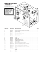
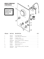
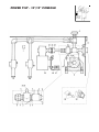
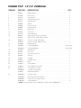
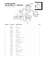
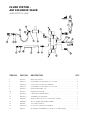
REMOTE CONTROL
ASSEMBLY
1
For Standard Direct Steam Mixer Kettles
NOTE: See SWITCH
CONFIGURATIONS
for applicable contact
cartridge/capacitor
combinations and
part numbers
16
INCLUDED WITH
ALL SWITCHES.
14
13
14
6
15
5
4
10
11
12
2
DI
7
Cl
GI
ev
TA
L
W
ela
AT
ER
17
nd
ME
TE
R
8
18
9
ITEM NO.
PART NO.
DESCRIPTION
1.
2.
3.
4.
5.
6.
7.
8.
9.
10.
11.
12.
13.
14.
15.
16.
17.
KE53479
KE53257
KE51857
KE53258
KE52710
KE52835
KE52936
KE51139
KE54402
KE01820
SK50370
KE54402
KE003209-6
KE003209-1
KE003209-7
KE52272
KE50753-9
Digital Temperature Controller and Indicator . . . . . . . . . . . . . . . . . . . . .1
Digital Counter . . . . . . . . . . . . . . . . . . . . . . . . . . . . . . . . . . . . . . . . . . . .1
Front Cover, Digital Counter . . . . . . . . . . . . . . . . . . . . . . . . . . . . . . . . .1
Panel Mount Socket . . . . . . . . . . . . . . . . . . . . . . . . . . . . . . . . . . . . . . . .1
Thermostat . . . . . . . . . . . . . . . . . . . . . . . . . . . . . . . . . . . . . . . . . . . . . . .1
Bracket for Thermostat . . . . . . . . . . . . . . . . . . . . . . . . . . . . . . . . . . . . . .1
Fuse . . . . . . . . . . . . . . . . . . . . . . . . . . . . . . . . . . . . . . . . . . . . . . . . . . . .1
Holder, Fuse . . . . . . . . . . . . . . . . . . . . . . . . . . . . . . . . . . . . . . . . . . . . . .1
Mounting Bracket, Fuse . . . . . . . . . . . . . . . . . . . . . . . . . . . . . . . . . . . . .1
Ambient Heater Assembly . . . . . . . . . . . . . . . . . . . . . . . . . . . . . . . . . . .1
Terminal Block . . . . . . . . . . . . . . . . . . . . . . . . . . . . . . . . . . . . . . . . . . . .1
Mounting Bracket, Terminal Block . . . . . . . . . . . . . . . . . . . . . . . . . . . . .1
Momentary Spring Return Switch Assembly . . . . . . . . . . . . . . . . . . . . .1
Switch Assembly, On/Off - Maintained . . . . . . . . . . . . . . . . . . . . . . . . . .2
Momentary Spring Return Switch Assembly . . . . . . . . . . . . . . . . . . . . .2
Cover . . . . . . . . . . . . . . . . . . . . . . . . . . . . . . . . . . . . . . . . . . . . . . . . . . .1
Relay . . . . . . . . . . . . . . . . . . . . . . . . . . . . . . . . . . . . . . . . . . . . . . . . . . . .1
KE95229
KE95229-1
Label: . . . . . . . . . . . . . . . . . . . . . . . . . . . . . . . . . . . . . . . . . . . . . . . . . . .1
English
French
18.
QTY.
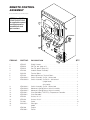
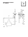
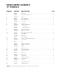
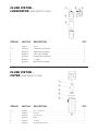
REMOTE CONTROL
ASSEMBLY
For Cook Chill Direct Steam Mixer Kettles
NOTE: See SWITCH
CONFIGURATIONS
for applicable contact
cartridge/capacitor
combinations and
part numbers
12
15
2
3
INCLUDED WITH
ALL SWITCHES.
16
7
8
9
5
10
11
17
6
9
1
4
5
6
ITEM NO.
PART NO.
DESCRIPTION
1.
2.
3.
4.
5.
6.
7.
8.
KE53257
SE50354
SE50354
KE01820
SK50370
KE54402
KE003209-1
KE003209-3
9.
10.
11.
12.
12.
13.
14.
15.
16.
17.
KE003209-1
KE003209-6
KE003209-7
KE53136-1
KE53136-2
KE53131
KE53132
FA11091
SK50315-1
Digital Counter . . . . . . . . . . . . . . . . . . . . . . . . . . . . . . . . . . . . . . . . . . . .1
Pen Tip, red (pkg. of 5) . . . . . . . . . . . . . . . . . . . . . . . . . . . . . . . . . . . . .1
Pen Tip, green (pkg. of 5) . . . . . . . . . . . . . . . . . . . . . . . . . . . . . . . . . .1
Ambient Heater Assembly . . . . . . . . . . . . . . . . . . . . . . . . . . . . . . . . . . .1
Terminal Block . . . . . . . . . . . . . . . . . . . . . . . . . . . . . . . . . . . . . . . . . . . .1
Mounting Bracket, Terminal Block . . . . . . . . . . . . . . . . . . . . . . . . . . . . .1
Switch Assembly, On/Off - Maintained . . . . . . . . . . . . . . . . . . . . . . . . . .1
Switch Assembly, On/Off/On - Maintained
(single kettle) . . . . . . . . . . . . . . . . . . . . . . . . . . . . . . .1
(twin kettle) . . . . . . . . . . . . . . . . . . . . . . . . . . . . . . . . .2
Switch Assembly, On/Off - Maintained . . . . . . . . . . . . . . . . . . . . . . . . . .2
Momentary Spring Return Switch Assembly . . . . . . . . . . . . . . . . . . . . .1
Momentary Spring Return Switch Assembly . . . . . . . . . . . . . . . . . . . . .2
Chart Recorder (TCR-DTCI) /Temperature Controller . . . . . . . . . . . . . .1
Chart Recorder . . . . . . . . . . . . . . . . . . . . . . . . . . . . . . . . . . . . . . . . . . . .1
Gasket, 24 1/4" . . . . . . . . . . . . . . . . . . . . . . . . . . . . . . . . . . . . . . . . . . . .2
Gasket, 15 3/4" . . . . . . . . . . . . . . . . . . . . . . . . . . . . . . . . . . . . . . . . . . . .2
Screw . . . . . . . . . . . . . . . . . . . . . . . . . . . . . . . . . . . . . . . . . . . . . . . . . . .10
Pilot Light . . . . . . . . . . . . . . . . . . . . . . . . . . . . . . . . . . . . . . . . . . . . . . . .1
Label: . . . . . . . . . . . . . . . . . . . . . . . . . . . . . . . . . . . . . . . . . . . . . . . . . . .1
English
French
KE95438
KE95438-1
14
13
QTY.
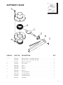
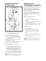
MAIN CONSOLE
CONTROLS
2
For Standard Direct Steam Mixer Kettles
1
9
10
L
I
F
T
NOTE: See SWITCH
CONFIGURATIONS
for applicable contact
cartridge/capacitor
combinations and
part numbers
11
12
13
O
AT FF/A
HE
UT
O
CO
OL
4
O
AT FF/A
HE
3
6
MI
X
UT
O
CO
OF
OL
F
INCLUDED WITH
ALL SWITCHES.
LI
FT
OF
F
6
ON
5
UP
6
OF
F
DO
W
N
7
14
8
ITEM NO.
PART NO.
DESCRIPTION
QTY.
1.
KE52190
Knob, Speed Control . . . . . . . . . . . . . . . . . . . . . . . . . . . . . . . . . . . . . . .1
2.
KE00860
Cable and Bracket, Speed Control (includes items 9 - 13) . . . . . . . . . .1
3.
KE53193
Emergency Switch . . . . . . . . . . . . . . . . . . . . . . . . . . . . . . . . . . . . . . . . .1
4.
KE53377
Push Button Contact Block . . . . . . . . . . . . . . . . . . . . . . . . . . . . . . . . . .1
5.
SK50315-1
Pilot Light . . . . . . . . . . . . . . . . . . . . . . . . . . . . . . . . . . . . . . . . . . . . . . . .1
6.
KE003209-5
Switch Assembly, On/Off/On - Maintained
(single kettle) . . . . . . . . . . . . . . . . . . . . . . . . . . . . . . .2
(twin kettle) . . . . . . . . . . . . . . . . . . . . . . . . . . . . . . . . .3
7.
KE003209-1
Switch Assembly, On/Off - Maintained . . . . . . . . . . . . . . . . . . . . . . . . . .1
8.
KE003209-7
Switch Assembly, On/Off/On - Momentary . . . . . . . . . . . . . . . . . . . . . . .1
9.
KE52180
Micro Switch . . . . . . . . . . . . . . . . . . . . . . . . . . . . . . . . . . . . . . . . . . . . . .1
10.
FA10032
Machine Screw, #4-40 x 5/8" LG . . . . . . . . . . . . . . . . . . . . . . . . . . . . . .2
12.
FA32002
Tooth Lock Washer #4 . . . . . . . . . . . . . . . . . . . . . . . . . . . . . . . . . . . . . .2
13.
14.
FA20000
KE95230-E
Hex Nut, #4-40 . . . . . . . . . . . . . . . . . . . . . . . . . . . . . . . . . . . . . . . . . . . .2
Label: . . . . . . . . . . . . . . . . . . . . . . . . . . . . . . . . . . . . . . . . . . . . . . . . . . .1
MAIN CONSOLE
CONTROLS
2
SP
For Cook Chill Direct Steam Mixer Kettles
EE
D
NOTE: See SWITCH
CONFIGURATIONS
for applicable contact
cartridge/capacitor
combinations and
part numbers
1
6
7
CO
5
NT
RO
8
L
4
6
7
9
10
9
3
FA
ST
2
1
MI
X
M
IX
ER
OF
F
INCLUDED WITH
ALL SWITCHES.
UN M
LEOTO
SS R
M
COWI
IN
NTLL
.
RONO
L TS
IS T
ATAR
LI
FT
"MT
IN
."
LI
11
UP
EM
ER
STGE
OPNC
Y
FT
OF
F
DO
W
N
5
4
3
12
ITEM NO.
PART NO.
DESCRIPTION
QTY.
1.
KE52190
Knob, Speed Control . . . . . . . . . . . . . . . . . . . . . . . . . . . . . . . . . . . . . . .1
2.
KE00860
Cable and Bracket, Speed Control . . . . . . . . . . . . . . . . . . . . . . . . . . . .1
3.
KE53193
Emergency Switch . . . . . . . . . . . . . . . . . . . . . . . . . . . . . . . . . . . . . . . . .1
4.
KE53377
Push Button Contact Block . . . . . . . . . . . . . . . . . . . . . . . . . . . . . . . . . .1
5.
KE003209-8
Switch Assembly, On/Off/On - Momentary . . . . . . . . . . . . . . . . . . . . . . .1
6.
KE52180
Micro Switch . . . . . . . . . . . . . . . . . . . . . . . . . . . . . . . . . . . . . . . . . . . . . .1
7.
FA10032
Machine Screw, #4-40 x 5/8" LG . . . . . . . . . . . . . . . . . . . . . . . . . . . . . .2
9.
FA32002
Tooth Lock Washer, #4 . . . . . . . . . . . . . . . . . . . . . . . . . . . . . . . . . . . . . .2
10.
FA20000
Hex Nut, #4-40 . . . . . . . . . . . . . . . . . . . . . . . . . . . . . . . . . . . . . . . . . . . .2
11.
KE003209-5
Switch Assembly, On/Off/On - Maintained . . . . . . . . . . . . . . . . . . . . . .1
12.
KE95230-E
Label: . . . . . . . . . . . . . . . . . . . . . . . . . . . . . . . . . . . . . . . . . . . . . . . . . . .1
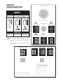
SWITCH
CONFIGURATION
SPEED CONTROL
5
4
6
L
IF
3
7
8
INDEX
Capacitor
T
For Standard Direct Steam Mixer Kettles
2
1
9
Contactor Cartridges
*
FAST
MIN.
MOTOR WILL NOT START
UNLESS CONTROL IS AT "MIN."
LEFT
KETTLE
OFF/AUTO
HEAT
COOL
EMERGENCY
STOP
RIGHT
KETTLE
OFF/AUTO
HEAT
COOL
PART NO.
LIFT
OFF
MIX
OFF
LIFT
UP
DOWN
EMPTY
EMPTY
NOTES: *For units built prior to December 2006, the complete
switch assembly must be ordered (see applicable
drawing).
MIXER
ON
EMPTY
OFF
EMPTY
MAIN
POWER
KE603208-9 KE603208-8
EMPTY
KE52074
Refer to Maintenance Section for Switch Disassembly
Instructions.
CONTROLLER
START
ON
EMPTY
EMPTY
EMPTY
EMPTY
EMPTY
EMPTY
INTERRUPT
OFF
EMPTY
CONTINUE RESET
ACTIVE
EMPTY
EMPTY
EMPTY
BYPASSED
KE95230-C
POWER
DIGITAL WATER METER
OPERATING INSTRUCTIONS
DISCONNECT FROM POWER
SUPPLY BEFORE SERVICING
1. Turn POWER switch ON.
2. Set required volume. Do not exceed kettle
capacity.
3. Locate delivery spout over desired kettle.
4. Press START switch downward to RESET.
Delivery will start at “0” and stop at preset volume.
5. To stop delivery any time, press INTERRUPT
switch downward.
6. To complete delivery after interrupting, press
START switch upward to CONTINUE.
7. Turn POWER switch to OFF when meter is not in use.
KE95229-G
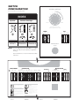
SWITCH
CONFIGURATION
SPEED CONTROL
For Cook Chill Direct Steam Mixer Kettles
5
4
6
IF
8
T
3
7
INDEX
L
2
1
9
Capacitor
Contactor Cartridges
FAST
MIN.
MOTOR WILL NOT START
UNLESS CONTROL IS AT "MIN."
MIXER
LIFT
OFF
OFF
UP
DOWN
EMPTY
LIFT
EMPTY
MIX
PART NO.
KE52074
KE603208-9
KE603208-8
EMERGENCY
STOP
NOTES: *For units built prior to December 2006, the complete
switch assembly must be ordered (see applicable
drawing).
Refer to Maintenance Section for Switch Disassembly
Instructions.
OFF
General Operation
ON
BYPASS ACTIVE
1. Turn MAIN POWER SWITCH to
"ON".
OFF
HEAT AUTO COOL
Lifting & Lowering
Bridge
OFF
MIX
LIFT
5
6
4
L
2. Turn MIXER SPEED CONTROL to
"MIN" and adjust to desired speed.
IF
T
3
7
2
MIN.
OFF
UP
DOWN
3. Turn and hold UP/DOWN SWITCH
"UP" to raise or "DOWN" to lower.
WARNING- Insure FAUCET SPOUT
is out of way before raising or lowering bridge.
OFF
MIX
LIFT
Mixing
Manual Heating/
Cooling
1. Turn ACTIVE/BYPASS SWITCH to
"BYPASS".
OFF
HEAT AUTO COOL
BYPASS ACTIVE
Automatic Heating/
Cooling
NOTE: TEMPERATURE PROBE on
MIXER BRIDGE must be covered
ith
i i
f th
i h
f
OFF
ON
Water Meter
Discharge Valve
EMPTY
EMPTY
EMPTY
EMPTY
EMPTY
EMPTY
EMPTY
EMPTY
START
OFF ON
For cool: open STEAM VALVE
completely.
1
FAST
BYPASS ACTIVE
START
CONTINUE RESET
2. Turn CONTROLLER SWITCH to
"HEAT" or "COOL".
3. For heat: open STEAM VALVE
completely to boil, or adjust to
regulate temperature.
1. Turn MIX/LIFT SWITCH to "LIFT".
SPEED CONTROL
8
9
WATER METER
INTERRUPT
EMPTY
ON
OFF
HEAT AUTO COOL
EMPTY
EMPTY
EMPTY
OFF
CONTROLLER
OFF
HEAT AUTO COOL
EMPTY
MAIN POWER
KE95230-C
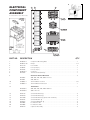
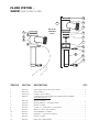
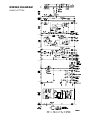
ELECTRICAL
COMPONENT
ASSEMBLY
1
2
9
For Standard Direct Steam Mixer Kettles
THERMAL
OVERLOAD
RELAY
24
8 15 19
7 17 19 21
12 18 20
ITEM
NO.
13
5
4
16
6
10 11 15 19
PART NO.
DESCRIPTION
1.
2.
4.
5.
6.
7.
8.
KE50343-7
KE50753-10
KE51139
SK50445
KE52936
KE50750-1
KE51982
Component Mounting Plate . . . . . . . . . . . . . . . . . . . . . . . . . . . . . . . . . . . . . . . .1
Relays . . . . . . . . . . . . . . . . . . . . . . . . . . . . . . . . . . . . . . . . . . . . . . . . . . . . . . . .2-7
Fuse Holder . . . . . . . . . . . . . . . . . . . . . . . . . . . . . . . . . . . . . . . . . . . . . . . . . . . . .2
Fuse (3 amps) . . . . . . . . . . . . . . . . . . . . . . . . . . . . . . . . . . . . . . . . . . . . . . . . . . .1
Fuse (1 amps) . . . . . . . . . . . . . . . . . . . . . . . . . . . . . . . . . . . . . . . . . . . . . . . . . . .1
Contactor . . . . . . . . . . . . . . . . . . . . . . . . . . . . . . . . . . . . . . . . . . . . . . . . . . . . . . .1
Thermal Overload Relay . . . . . . . . . . . . . . . . . . . . . . . . . . . . . . . . . . . . . . . . . . .1
KE52055
KE52051
Heater for Thermal Overload . . . . . . . . . . . . . . . . . . . . . . . . . . . . . . . . . . . . . .3
200, 208, 220, 240, 380 & 415 volt
440, 480 volt
SK50055-1
SK50054-1
Terminal Block Sections . . . . . . . . . . . . . . . . . . . . . . . . . . . . . . . . . . . . . . . . . .3-6
Terminal Block End Section . . . . . . . . . . . . . . . . . . . . . . . . . . . . . . . . . . . . . . . .1
KE53838-5
KE53838-6
Transformer . . . . . . . . . . . . . . . . . . . . . . . . . . . . . . . . . . . . . . . . . . . . . . . . . . . .1
200, 208, 220, 240, 440 & 480 volt
380 & 415 volt
FA10133
FA10239
FA12500
FA10245
FA10362
FA32005
FA32006
KE02274
Screws #6-32x3/8" lg. . . . . . . . . . . . . . . . . . . . . . . . . . . . . . . . . . . . . . . . . . . . . .3
Screws #8-32x3/8" lg. . . . . . . . . . . . . . . . . . . . . . . . . . . . . . . . . . . . . . . . . . . . . .6
Screws #8-32x3/8" lg. (brass with undercut) . . . . . . . . . . . . . . . . . . . . . . . . . . .1
Screws #8-32x1" lg. . . . . . . . . . . . . . . . . . . . . . . . . . . . . . . . . . . . . . . . . . . . . . . .2
Screws #10-32x3/8" lg. . . . . . . . . . . . . . . . . . . . . . . . . . . . . . . . . . . . . . . . . . . . .4
Lockwashers #8 . . . . . . . . . . . . . . . . . . . . . . . . . . . . . . . . . . . . . . . . . . . . . . . . .8
Lockwashers #10 . . . . . . . . . . . . . . . . . . . . . . . . . . . . . . . . . . . . . . . . . . . . . . . .4
Capacitor Assembly . . . . . . . . . . . . . . . . . . . . . . . . . . . . . . . . . . . . . . . . . . . . . .3
9.
10.
11.
12.
13.
15.
16.
17.
18.
19.
20.
21.
QTY.
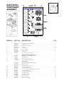
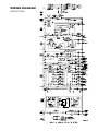
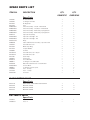
ELECTRICAL
COMPONENT
ASSEMBLY
1
2
3 15 21
24 21
11
For Cook Chill Direct Steam Mixer Kettles
THERMAL
OVERLOAD
RELAY
MAIN TERMINAL BLOCK
24
10 17 22
8
7
9 19 22 25
15 6
14 20 23
18
4
22 17 13 12
ITEM NO.
PART NO.
DESCRIPTION
1.
2.
3.
4.
6.
7.
8.
9.
10.
KE50343-8
KE52710
KE52835
KE50753-10
KE51139
SK50445
KE52936
KE50750-1
KE51982
Component Mounting Plate . . . . . . . . . . . . . . . . . . . . . . . . . . . . . . . . . . . . . . . .1
Thermostat . . . . . . . . . . . . . . . . . . . . . . . . . . . . . . . . . . . . . . . . . . . . . . . . . . . . .1
Bracket for Thermostat . . . . . . . . . . . . . . . . . . . . . . . . . . . . . . . . . . . . . . . . . . . .1
Relays . . . . . . . . . . . . . . . . . . . . . . . . . . . . . . . . . . . . . . . . . . . . . . . . . . . . . . . .6-9
Fuse Holder . . . . . . . . . . . . . . . . . . . . . . . . . . . . . . . . . . . . . . . . . . . . . . . . . . . . .2
Fuse (3 amps) . . . . . . . . . . . . . . . . . . . . . . . . . . . . . . . . . . . . . . . . . . . . . . . . . . .1
Fuse (1 amps) . . . . . . . . . . . . . . . . . . . . . . . . . . . . . . . . . . . . . . . . . . . . . . . . . . .1
Contactor . . . . . . . . . . . . . . . . . . . . . . . . . . . . . . . . . . . . . . . . . . . . . . . . . . . . . . .1
Thermal Overload Relays . . . . . . . . . . . . . . . . . . . . . . . . . . . . . . . . . . . . . . . . . .1
KE52055
KE52051
Heater for Thermal Overload . . . . . . . . . . . . . . . . . . . . . . . . . . . . . . . . . . . . . .3
200, 208, 220, 240, 380 & 415 volt
440, 480 volt
SK50055-1
SK50054-1
Terminal Block Sections . . . . . . . . . . . . . . . . . . . . . . . . . . . . . . . . . . . . . . . . . . .3
Terminal Block End Section . . . . . . . . . . . . . . . . . . . . . . . . . . . . . . . . . . . . . . . .1
KE53838-5
KE53838-6
Transformer . . . . . . . . . . . . . . . . . . . . . . . . . . . . . . . . . . . . . . . . . . . . . . . . . . . .1
200, 208, 220, 240, 440 & 480 volt
380 & 415 volt
FA10133
FA10135
FA10239
FA12500
FA10245
FA10362
FA32004
FA32005
FA32006
FA20002
KE02274
Screws #6-32x3/8" lg. . . . . . . . . . . . . . . . . . . . . . . . . . . . . . . . . . . . . . . . . . . . . .5
Screws #6-32x1/2" lg. . . . . . . . . . . . . . . . . . . . . . . . . . . . . . . . . . . . . . . . . . . . .7-11
Screws #8-32x3/8" lg. . . . . . . . . . . . . . . . . . . . . . . . . . . . . . . . . . . . . . . . . . . . . .6
Screws #8-32x3/8" lg. (brass with undercut) . . . . . . . . . . . . . . . . . . . . . . . . . . .1
Screws #8-32x1" lg. . . . . . . . . . . . . . . . . . . . . . . . . . . . . . . . . . . . . . . . . . . . . . . .2
Screws #10-32x3/8" lg. . . . . . . . . . . . . . . . . . . . . . . . . . . . . . . . . . . . . . . . . . . . .4
Lockwashers #6 . . . . . . . . . . . . . . . . . . . . . . . . . . . . . . . . . . . . . . . . . . . . . . . . .2
Lockwashers #8 . . . . . . . . . . . . . . . . . . . . . . . . . . . . . . . . . . . . . . . . . . . . . . . . .8
Lockwashers #10 . . . . . . . . . . . . . . . . . . . . . . . . . . . . . . . . . . . . . . . . . . . . . . . .4
Hex Nut #6-32 . . . . . . . . . . . . . . . . . . . . . . . . . . . . . . . . . . . . . . . . . . . . . . . . . . .1
Capacitor Assembly . . . . . . . . . . . . . . . . . . . . . . . . . . . . . . . . . . . . . . . . . . . . . .3
11.
12.
13.
14.
15.
16.
17.
18.
19.
20.
21.
22.
23.
24.
25.
QTY.
PLUMBING
ASSEMBLY 10" CONSOLE
ITEM NO.
PART NO.
DESCRIPTION
1.
KE02055-2
KE02055-4
FI00267
FI00629-31
FI00179
FI00629-36
FI00152
KE51653
KE51367
KE54834-3
SE50405
SE50406
KE54834-4
SE50410
SE50404
KE54834-8
SE50409
SE50404
FI00629-30
FI00063
KE51654
KE53008
FI00629-29
FI0062919
KE54834-5
SE50407
SE50401
KE54834-4
SE50410
SE50404
FI00629-4
FI00629-7
Steam Valve 3/4" . . . . . . . . . . . . . . . . . . . . . . . . . . . . . . . . . . . . . . . . . . . . . . . . .1
Steam Valve 1 1/4"
Coupling . . . . . . . . . . . . . . . . . . . . . . . . . . . . . . . . . . . . . . . . . . . . . . . . . . . . . . .1
Nipple . . . . . . . . . . . . . . . . . . . . . . . . . . . . . . . . . . . . . . . . . . . . . . . . . . . . . . . . .1
Tee . . . . . . . . . . . . . . . . . . . . . . . . . . . . . . . . . . . . . . . . . . . . . . . . . . . . . . . . . . . .1
Nipple . . . . . . . . . . . . . . . . . . . . . . . . . . . . . . . . . . . . . . . . . . . . . . . . . . . . . . . . .4
Street Elbow . . . . . . . . . . . . . . . . . . . . . . . . . . . . . . . . . . . . . . . . . . . . . . . . . . . .3
Check Valve 3/4" . . . . . . . . . . . . . . . . . . . . . . . . . . . . . . . . . . . . . . . . . . . . . . . . .2
Check Valve 1 1/4"
* Solenoid Valve, 3/4" - 50 psi. . . . . . . . . . . . . . . . . . . . . . . . . . . . . . . . . . . . . . .1
Rebuild Kit
Replacement Coil
* Solenoid Valve, 3/4" - 100 psi. . . . . . . . . . . . . . . . . . . . . . . . . . . . . . . . . . . . . .1
Rebuild Kit
Replacement Coil
* Solenoid Valve, 1 1/4" - 100 psi. . . . . . . . . . . . . . . . . . . . . . . . . . . . . . . . . . . .1
Rebuild Kit
Replacement Coil
Nipple . . . . . . . . . . . . . . . . . . . . . . . . . . . . . . . . . . . . . . . . . . . . . . . . . . . . . . . . .1
Elbow . . . . . . . . . . . . . . . . . . . . . . . . . . . . . . . . . . . . . . . . . . . . . . . . . . . . . . . . . .2
Y-Strainer 3/4" . . . . . . . . . . . . . . . . . . . . . . . . . . . . . . . . . . . . . . . . . . . . . . . . . . .1
Y-Strainer 1 1/4"
Nipple . . . . . . . . . . . . . . . . . . . . . . . . . . . . . . . . . . . . . . . . . . . . . . . . . . . . . . . . .1
Nipple . . . . . . . . . . . . . . . . . . . . . . . . . . . . . . . . . . . . . . . . . . . . . . . . . . . . . . . . .1
* Solenoid Valve, 3/4" - 50 psi. . . . . . . . . . . . . . . . . . . . . . . . . . . . . . . . . . . . . . .1
Rebuild Kit
Replacement Coil
* Solenoid Valve, 3/4" - 100 psi. . . . . . . . . . . . . . . . . . . . . . . . . . . . . . . . . . . . . .1
Rebuild Kit
Replacement Coil
Nipple . . . . . . . . . . . . . . . . . . . . . . . . . . . . . . . . . . . . . . . . . . . . . . . . . . . . . . . . .1
Nipple . . . . . . . . . . . . . . . . . . . . . . . . . . . . . . . . . . . . . . . . . . . . . . . . . . . . . . . . .1
2.
3.
4.
5.
6.
7.
8.
9.
10.
11.
.
12.
13.
14.
15.
16.
*NOTE: See SOLENOID VALVE MAINTENANCE section for further information.
100 gallons and up use the larger valves.
QTY.
PLUMBING ASSEMBLY - 18" CONSOLE
ITEM NO.
PART NO.
DESCRIPTION
1.
FI00096
Union . . . . . . . . . . . . . . . . . . . . . . . . . . . . . . . . . . . . . . . . . . . . . . . . . . . . . . . . . .1
2.
F100179
Tee . . . . . . . . . . . . . . . . . . . . . . . . . . . . . . . . . . . . . . . . . . . . . . . . . . . . . . . . . . . .1
3.
F105130
Reducing Nipple . . . . . . . . . . . . . . . . . . . . . . . . . . . . . . . . . . . . . . . . . . . . . . . . .1
4.
KE52702
Y-Strainer, 1/2" . . . . . . . . . . . . . . . . . . . . . . . . . . . . . . . . . . . . . . . . . . . . . . . . . . .1
5.
KE52701
Steam Trap . . . . . . . . . . . . . . . . . . . . . . . . . . . . . . . . . . . . . . . . . . . . . . . . . . . . .1
6.
FI00151
Street Elbow . . . . . . . . . . . . . . . . . . . . . . . . . . . . . . . . . . . . . . . . . . . . . . . . . . . .3
7.
FI00441
Reducing Bushing . . . . . . . . . . . . . . . . . . . . . . . . . . . . . . . . . . . . . . . . . . . . . . . .1
8.
FI00363
Reducing Elbow . . . . . . . . . . . . . . . . . . . . . . . . . . . . . . . . . . . . . . . . . . . . . . . . .1
9.
KE54834-5
* Solenoid Valve, 3/4" - 50 psi. . . . . . . . . . . . . . . . . . . . . . . . . . . . . . . . . . . . . . .1
SE50407
SE50401
KE54834-4
QTY.
Rebuild Kit
Replacement Coil
* Solenoid Valve, 3/4" - 100 psi. . . . . . . . . . . . . . . . . . . . . . . . . . . . . . . . . . . . . .1
SE50410
Rebuild Kit
SE50404
Replacement Coil
10.
FI00143
Street Elbow . . . . . . . . . . . . . . . . . . . . . . . . . . . . . . . . . . . . . . . . . . . . . . . . . . . .3
11.
KE51653
Check Valve . . . . . . . . . . . . . . . . . . . . . . . . . . . . . . . . . . . . . . . . . . . . . . . . . . . .1
12.
KE51654
Y-Stainer . . . . . . . . . . . . . . . . . . . . . . . . . . . . . . . . . . . . . . . . . . . . . . . . . . . . . . .1
13.
KE52666
Thermostat Mtg. Block . . . . . . . . . . . . . . . . . . . . . . . . . . . . . . . . . . . . . . . . . . . .1
14.
UR50077
Thermostat . . . . . . . . . . . . . . . . . . . . . . . . . . . . . . . . . . . . . . . . . . . . . . . . . . . . .1
15.
FA11052
Bindinghead Screw . . . . . . . . . . . . . . . . . . . . . . . . . . . . . . . . . . . . . . . . . . . . . . .1
16.
FA11060
Bindinghead Screw . . . . . . . . . . . . . . . . . . . . . . . . . . . . . . . . . . . . . . . . . . . . . . .1
17.
FI00178
Tee . . . . . . . . . . . . . . . . . . . . . . . . . . . . . . . . . . . . . . . . . . . . . . . . . . . . . . . . . . . .1
18.
FI05089
Reducing Nipple . . . . . . . . . . . . . . . . . . . . . . . . . . . . . . . . . . . . . . . . . . . . . . . . .1
19.
KE54834-2
SE50408
SE50404
* Solenoid Valve, 3/8" . . . . . . . . . . . . . . . . . . . . . . . . . . . . . . . . . . . . . . . . . . . . .1
Rebuild Kit
Replacement Coil
*NOTE: See SOLENOID VALVE MAINTENANCE section for further information.
MANUAL TILT - 10" CONSOLE
ITEM NO.
PART NO.
DESCRIPTION
QTY.
1.
KE51730
Tilt Shaft Bearing . . . . . . . . . . . . . . . . . . . . . . . . . . . . . . . . . . . . . . . . . . . . . . . . .1
2.
KE50375
Tilt Shaft, Small Gear, 40 to 80 gal. . . . . . . . . . . . . . . . . . . . . . . . . . . . . . . . . . .1
KE503751
Tilt Shaft, Small Gear, 100 gal. and up . . . . . . . . . . . . . . . . . . . . . . . . . . . . . . . .1
3.
FA19505
Handwheel Allen Screw, Hex Socket . . . . . . . . . . . . . . . . . . . . . . . . . . . . . . . . .1
4.
KE00508
Handwheel Assembly . . . . . . . . . . . . . . . . . . . . . . . . . . . . . . . . . . . . . . . . . . . . .1
5.
FA95007-1
Retaining Ring . . . . . . . . . . . . . . . . . . . . . . . . . . . . . . . . . . . . . . . . . . . . . . . . . . .1
6.
FA05002-6
"O" Ring . . . . . . . . . . . . . . . . . . . . . . . . . . . . . . . . . . . . . . . . . . . . . . . . . . . . . . . .2
7.
FA95048
Woodruff Key . . . . . . . . . . . . . . . . . . . . . . . . . . . . . . . . . . . . . . . . . . . . . . . . . . . .1
8.
FA19201
Set Screw . . . . . . . . . . . . . . . . . . . . . . . . . . . . . . . . . . . . . . . . . . . . . . . . . . . . . .1
9.
10.
KE00151
Segment Gear, Small, up to 60 gal. . . . . . . . . . . . . . . . . . . . . . . . . . . . . . . . . . .1
KE52833
Segment Gear, Large, 80 gal. and up . . . . . . . . . . . . . . . . . . . . . . . . . . . . . . . .1
KE00699
Trunnion Housing . . . . . . . . . . . . . . . . . . . . . . . . . . . . . . . . . . . . . . . . . . . . . . . .1
11.
FA19177
Hex-Socket Set Screw . . . . . . . . . . . . . . . . . . . . . . . . . . . . . . . . . . . . . . . . . . . . .1
12.
FA20047
Jam Nut . . . . . . . . . . . . . . . . . . . . . . . . . . . . . . . . . . . . . . . . . . . . . . . . . . . . . . . .1
13.
KE52191
Roller Bearing . . . . . . . . . . . . . . . . . . . . . . . . . . . . . . . . . . . . . . . . . . . . . . . . . . .2
14.
KE52193
Thrust Bearing Spacer . . . . . . . . . . . . . . . . . . . . . . . . . . . . . . . . . . . . . . . . . . . .2
15.
KE50315
Worm Gear . . . . . . . . . . . . . . . . . . . . . . . . . . . . . . . . . . . . . . . . . . . . . . . . . . . . .1
16.
FA95005
Tension Pin . . . . . . . . . . . . . . . . . . . . . . . . . . . . . . . . . . . . . . . . . . . . . . . . . . . . .1
17.
FA95008
Hex Nut 3/4-16 . . . . . . . . . . . . . . . . . . . . . . . . . . . . . . . . . . . . . . . . . . . . . . . . . .2
18.
FA30088
Washer . . . . . . . . . . . . . . . . . . . . . . . . . . . . . . . . . . . . . . . . . . . . . . . . . . . . . . . .3
19.
KE52192
Thrust Washer . . . . . . . . . . . . . . . . . . . . . . . . . . . . . . . . . . . . . . . . . . . . . . . . . . .4
POWER TILT - 10"/12" CONSOLE
POWER TILT - 10"/12" CONSOLE
ITEM NO.
PART NO.
DESCRIPTION
QTY.
1.
KE50581
Bridge Rectifier . . . . . . . . . . . . . . . . . . . . . . . . . . . . . . . . . . . . . . . . . . . . . . . . . .1
2.
KE51007
Micro Switch . . . . . . . . . . . . . . . . . . . . . . . . . . . . . . . . . . . . . . . . . . . . . . . . . . . .2
3.
KE52192
Thrust Washer . . . . . . . . . . . . . . . . . . . . . . . . . . . . . . . . . . . . . . . . . . . . . . . . . . .4
4.
KE52193
Thrust Bearing Spacer . . . . . . . . . . . . . . . . . . . . . . . . . . . . . . . . . . . . . . . . . . . .2
5.
KE52191
Roller Bearing . . . . . . . . . . . . . . . . . . . . . . . . . . . . . . . . . . . . . . . . . . . . . . . . . . .2
6.
FA30088
Washer . . . . . . . . . . . . . . . . . . . . . . . . . . . . . . . . . . . . . . . . . . . . . . . . . . . . . . . .2
8.
FA95008
Hex Nut, 3/4-16 . . . . . . . . . . . . . . . . . . . . . . . . . . . . . . . . . . . . . . . . . . . . . . . . . .2
9.
SE00028
Knob Assembly . . . . . . . . . . . . . . . . . . . . . . . . . . . . . . . . . . . . . . . . . . . . . . . . . .1
11.
KE50315
Worm Gear,
12.
FA95005
Tension Pin . . . . . . . . . . . . . . . . . . . . . . . . . . . . . . . . . . . . . . . . . . . . . . . . . . . . .1
13.
KE51730
Tilt Shaft Bearing . . . . . . . . . . . . . . . . . . . . . . . . . . . . . . . . . . . . . . . . . . . . . . . . .1
14.
KE00151
Segment Gear, Small, up to 60 gal. . . . . . . . . . . . . . . . . . . . . . . . . . . . . . . . . . .1
KE52833
Segment Gear, Large, 80 gal. and up . . . . . . . . . . . . . . . . . . . . . . . . . . . . . . . .1
KE00699
Trunnion Housing, 40 to 80 gal. . . . . . . . . . . . . . . . . . . . . . . . . . . . . . . . . . . . . .1
15.
. . . . . . . . . . . . . . . . . . . . . . . . . . . . . . . . . . . . . . . . . . . . . . . . . . . .1
KE001182
Trunnion Housing, 100 gal. and up . . . . . . . . . . . . . . . . . . . . . . . . . . . . . . . . . .1
16.
FA95007-1
Retaining Ring . . . . . . . . . . . . . . . . . . . . . . . . . . . . . . . . . . . . . . . . . . . . . . . . . . .1
17.
FA05002-6
"O" Ring (40-80 gal.) . . . . . . . . . . . . . . . . . . . . . . . . . . . . . . . . . . . . . . . .2 (per kettle)
FA05002-27
"O" Ring (40-80 gal.) . . . . . . . . . . . . . . . . . . . . . . . . . . . . . . . . . . . . . . . .2 (per kettle)
18.
FA95048
Woodruff Key . . . . . . . . . . . . . . . . . . . . . . . . . . . . . . . . . . . . . . . . . . . . . . . . . . . .1
19.
FA19201
Set Screw . . . . . . . . . . . . . . . . . . . . . . . . . . . . . . . . . . . . . . . . . . . . . . . . . . . . . .1
20.
FA19177
Hex-Socket Set Screw . . . . . . . . . . . . . . . . . . . . . . . . . . . . . . . . . . . . . . . . . . . . .1
21.
FA20047
Jam Nut . . . . . . . . . . . . . . . . . . . . . . . . . . . . . . . . . . . . . . . . . . . . . . . . . . . . . . . .1
22.
KE50582
Coupling . . . . . . . . . . . . . . . . . . . . . . . . . . . . . . . . . . . . . . . . . . . . . . . . . . . . . . .2
23.
KE50583
Coupling Insert . . . . . . . . . . . . . . . . . . . . . . . . . . . . . . . . . . . . . . . . . . . . . . . . . .1
25.
KE52832-1
Motor . . . . . . . . . . . . . . . . . . . . . . . . . . . . . . . . . . . . . . . . . . . . . . . . . . . . . . . . . .1
26.
SK50055-1
Terminal Block . . . . . . . . . . . . . . . . . . . . . . . . . . . . . . . . . . . . . . . . . . . . . . . . . . .1
27.
SK50054-1
Terminal Block End-Section . . . . . . . . . . . . . . . . . . . . . . . . . . . . . . . . . . . . . . . .1
28.
29.
KE50579-1
Circuit Breaker. 1.3 Amp. . . . . . . . . . . . . . . . . . . . . . . . . . . . . . . . . . . . . . . . . . .1
FA05002-34
"O" Ring, Circuit Breaker . . . . . . . . . . . . . . . . . . . . . . . . . . . . . . . . . . . . . . . . . . .1
KE50580
Water Resistant Boot . . . . . . . . . . . . . . . . . . . . . . . . . . . . . . . . . . . . . . . . . . . . . .1
KE003209-11
Complete Switch . . . . . . . . . . . . . . . . . . . . . . . . . . . . . . . . . . . . . . . . . . . . . . . . .1
KE603208-4
KE603208-7
KE603208-9
Momentary Switch Activator*** . . . . . . . . . . . . . . . . . . . . . . . . . . . . . . . . . . . . . .1
Contact Section Holder, Latch*** . . . . . . . . . . . . . . . . . . . . . . . . . . . . . . . . . . . .1
Contact Block*** . . . . . . . . . . . . . . . . . . . . . . . . . . . . . . . . . . . . . . . . . . . . . . . . . 4
***NOTE: for units built prior to Dec. 2006 order Complete Switch KE003209-11
WATER METER ASSEMBLY 18" CONSOLE
WATER METER ASSEMBLY 18" CONSOLE
ITEM NO.
PART NO.
1.
FI05058
3/4" Cross . . . . . . . . . . . . . . . . . . . . . . . . . . . . . . . . . . . . . . . . . . . . . . . . . . . . . .1
2.
KE02055-2
Steam Valve Modification . . . . . . . . . . . . . . . . . . . . . . . . . . . . . . . . . . . . . . . . . .2
3.
N0640B4.5
Nipple . . . . . . . . . . . . . . . . . . . . . . . . . . . . . . . . . . . . . . . . . . . . . . . . . . . . . . . . .2
4.
FI00063
Elbow 90 degree . . . . . . . . . . . . . . . . . . . . . . . . . . . . . . . . . . . . . . . . . . . . . . . . .4
5.
FI000356
Reducing Bushing . . . . . . . . . . . . . . . . . . . . . . . . . . . . . . . . . . . . . . . . . . . . . . . .1
6.
KE600812-1
Street Elbow . . . . . . . . . . . . . . . . . . . . . . . . . . . . . . . . . . . . . . . . . . . . . . . . . . . .1
7.
FI05029
Hose Barb . . . . . . . . . . . . . . . . . . . . . . . . . . . . . . . . . . . . . . . . . . . . . . . . . . . . . .2
KE54834-5
* Solenoid Valve, 3/4" . . . . . . . . . . . . . . . . . . . . . . . . . . . . . . . . . . . . . . . . . . . . .1
8.
9.
10.
11.
DESCRIPTION
SE50407
Rebuild Kit
SE50401
Replacement Coil
QTY.
N0640B3
Nipple, Gallon Meter . . . . . . . . . . . . . . . . . . . . . . . . . . . . . . . . . . . . . . . . . . . . . .1
N0640B3.5
Nipple, Litre Meter
FI00363-3
Reducing Elbow 90 Degree . . . . . . . . . . . . . . . . . . . . . . . . . . . . . . . . . . . . . . . .1
KE51861
Gallon Meter . . . . . . . . . . . . . . . . . . . . . . . . . . . . . . . . . . . . . . . . . . . . . . . . . . . .1
KE51860
Litre Meter
12.
FI00062
Elbow 90 Degree . . . . . . . . . . . . . . . . . . . . . . . . . . . . . . . . . . . . . . . . . . . . . . . . .1
13.
KE52173
1/2"1.D. Hot Water Wash-up Hose . . . . . . . . . . . . . . . . . . . . . . . . . . . . . . . . . . .1
14.
FI05220-3
Hose Clamp . . . . . . . . . . . . . . . . . . . . . . . . . . . . . . . . . . . . . . . . . . . . . . . . . . . .2
15.
FI00179
Tee . . . . . . . . . . . . . . . . . . . . . . . . . . . . . . . . . . . . . . . . . . . . . . . . . . . . . . . . . . . .1
16.
FI05074
Adapter, Gallon Meter . . . . . . . . . . . . . . . . . . . . . . . . . . . . . . . . . . . . . . . . . . . . .2
KE600362
Adapter, Litre Meter
17.
N0640B1.5
Nipple . . . . . . . . . . . . . . . . . . . . . . . . . . . . . . . . . . . . . . . . . . . . . . . . . . . . . . . . .1
18.
FA11091
Machine Screw . . . . . . . . . . . . . . . . . . . . . . . . . . . . . . . . . . . . . . . . . . . . . . . . . .8
20.
KE51369
Steam Valve Flange . . . . . . . . . . . . . . . . . . . . . . . . . . . . . . . . . . . . . . . . . . . . . .2
21.
SE00028
Knob Assembly . . . . . . . . . . . . . . . . . . . . . . . . . . . . . . . . . . . . . . . . . . . . . . . . . .2
22.
KE95321
Label "Hot" . . . . . . . . . . . . . . . . . . . . . . . . . . . . . . . . . . . . . . . . . . . . . . . . . . . . . .1
23.
KE95322
Label "Cold" . . . . . . . . . . . . . . . . . . . . . . . . . . . . . . . . . . . . . . . . . . . . . . . . . . . . .1
24.
SD50097
Flanged Nut . . . . . . . . . . . . . . . . . . . . . . . . . . . . . . . . . . . . . . . . . . . . . . . . . . . . .1
25.
KE51585
Faucet Spout Fitting . . . . . . . . . . . . . . . . . . . . . . . . . . . . . . . . . . . . . . . . . . . . . .1
26.
KE50825-12
Faucet Spout . . . . . . . . . . . . . . . . . . . . . . . . . . . . . . . . . . . . . . . . . . . . . . . . . . . .1
27.
FA05002-19
"O" Ring . . . . . . . . . . . . . . . . . . . . . . . . . . . . . . . . . . . . . . . . . . . . . . . . . . . . . . . .1
28.
FA95022
Retaining Ring Carter . . . . . . . . . . . . . . . . . . . . . . . . . . . . . . . . . . . . . . . . . . . . .1
29.
KE51736
Long Faucet Nut . . . . . . . . . . . . . . . . . . . . . . . . . . . . . . . . . . . . . . . . . . . . . . . . .1
*NOTE: See SOLENOID VALVE MAINTENANCE section for further information.
FLUSH PISTON VALVE (USED PRIOR TO 2003)
ITEM NO.
PART NO.
DESCRIPTION
QTY.
T40430
Valve Assembly (includes parts 1 - 16) . . . . . . . . . . . . . . . . . . . . . . . . .1
1.
FA05000
"O" Ring, Cylinder Head . . . . . . . . . . . . . . . . . . . . . . . . . . . . . . . . . . . . .1
2.
KE52345
Piston Shaft . . . . . . . . . . . . . . . . . . . . . . . . . . . . . . . . . . . . . . . . . . . . . . .1
3.
KE52346
Air seal . . . . . . . . . . . . . . . . . . . . . . . . . . . . . . . . . . . . . . . . . . . . . . . . . .1
4.
KE52347
Sani-Clamp Seal, 4”
5.
KE52344
Sani-Clamp, 4” . . . . . . . . . . . . . . . . . . . . . . . . . . . . . . . . . . . . . . . . . . . .1
6.
FA05002-22
"O" Ring, Cylinder Body . . . . . . . . . . . . . . . . . . . . . . . . . . . . . . . . . . . . .2
7.
FA05002-21
"O" Ring, Piston . . . . . . . . . . . . . . . . . . . . . . . . . . . . . . . . . . . . . . . . . . . .2
8.
KE52315
Piston . . . . . . . . . . . . . . . . . . . . . . . . . . . . . . . . . . . . . . . . . . . . . . . . . . .1
9.
10.-13.
KE52335
SE00040
Compression Spring . . . . . . . . . . . . . . . . . . . . . . . . . . . . . . . . . . . . . . . .1
Supply Hose Assembly, Piston . . . . . . . . . . . . . . . . . . . . . . . . . . . . . . . .1
10.
KE52341
Hose Barb, 1/8” x 1/4” . . . . . . . . . . . . . . . . . . . . . . . . . . . . . . . . . . . . . .3
11.
KE52340
Supply Hose, 8” . . . . . . . . . . . . . . . . . . . . . . . . . . . . . . . . . . . . . . . . . . .1
12.
KE52342
Hose Barb, 1/4” x 1/4” . . . . . . . . . . . . . . . . . . . . . . . . . . . . . . . . . . . . . .1
13.
KE52338
Quick Connect Male End . . . . . . . . . . . . . . . . . . . . . . . . . . . . . . . . . . . .1
14.
KE52327
Piston Top . . . . . . . . . . . . . . . . . . . . . . . . . . . . . . . . . . . . . . . . . . . . . . . .1
15.
KE52328
Piston Cylinder . . . . . . . . . . . . . . . . . . . . . . . . . . . . . . . . . . . . . . . . . . . .1
16.
KE52314
Bottom Nut . . . . . . . . . . . . . . . . . . . . . . . . . . . . . . . . . . . . . . . . . . . . . . .1
. . . . . . . . . . . . . . . . . . . . . . . . . . . . . . . . . . . . . . .1
FLUSH PISTON AIR SYSTEM, 10" CONSOLE
(USED PRIOR TO 2003)
ITEM NO.
PART NO.
DESCRIPTION
QTY.
1.
FA30512
Spacer . . . . . . . . . . . . . . . . . . . . . . . . . . . . . . . . . . . . . . . . . . . . . . . . . . . . . . . . .1
2.
FA32500
Tooth lockwasher . . . . . . . . . . . . . . . . . . . . . . . . . . . . . . . . . . . . . . . . . . . . . . . . .1
3.
KE52697
Locking nut . . . . . . . . . . . . . . . . . . . . . . . . . . . . . . . . . . . . . . . . . . . . . . . . . . . . .1
4.
KE52931
Adapter . . . . . . . . . . . . . . . . . . . . . . . . . . . . . . . . . . . . . . . . . . . . . . . . . . . . . . . .1
5.
FI00266
Coupling . . . . . . . . . . . . . . . . . . . . . . . . . . . . . . . . . . . . . . . . . . . . . . . . . . . . . . .1
6.
FI00595-17
Nipple 1/2" NPT . . . . . . . . . . . . . . . . . . . . . . . . . . . . . . . . . . . . . . . . . . . . . . . . . .2
7.
FI00178
Tee 1/2" NPT . . . . . . . . . . . . . . . . . . . . . . . . . . . . . . . . . . . . . . . . . . . . . . . . . . . .2
8.
FI00595-12
Nipple 1/2" NPT . . . . . . . . . . . . . . . . . . . . . . . . . . . . . . . . . . . . . . . . . . . . . . . . . .1
9.
FI05047
Bushing . . . . . . . . . . . . . . . . . . . . . . . . . . . . . . . . . . . . . . . . . . . . . . . . . . . . . . . .1
10.
KE52342
Hose Barb . . . . . . . . . . . . . . . . . . . . . . . . . . . . . . . . . . . . . . . . . . . . . . . . . . . . . .3
11.
FI05167
Hose Barb 90 Degree Elbow . . . . . . . . . . . . . . . . . . . . . . . . . . . . . . . . . . . . . . .6
12.
KE52815
Airline Lubricator . . . . . . . . . . . . . . . . . . . . . . . . . . . . . . . . . . . . . . . . . . . . . . . . .1
13.
KE52895
Air Regulator . . . . . . . . . . . . . . . . . . . . . . . . . . . . . . . . . . . . . . . . . . . . . . . . . . . .1
14.
KE52339
Female End Quick Connect . . . . . . . . . . . . . . . . . . . . . . . . . . . . . . . . . . . . . . . .1
15.
KE52932
Bracket For Lubricator . . . . . . . . . . . . . . . . . . . . . . . . . . . . . . . . . . . . . . . . . . . .1
16.
FA32006
Toothlock Washer . . . . . . . . . . . . . . . . . . . . . . . . . . . . . . . . . . . . . . . . . . . . . . . .4
17.
FA21006
Nut . . . . . . . . . . . . . . . . . . . . . . . . . . . . . . . . . . . . . . . . . . . . . . . . . . . . . . . . . . . .4
18.
FA11091
Machine Screw . . . . . . . . . . . . . . . . . . . . . . . . . . . . . . . . . . . . . . . . . . . . . . . . . .2
19.
KE53209
Quick Exhaust Valve . . . . . . . . . . . . . . . . . . . . . . . . . . . . . . . . . . . . . . . . . . . . . .1
20.
KE53210
Muffler . . . . . . . . . . . . . . . . . . . . . . . . . . . . . . . . . . . . . . . . . . . . . . . . . . . . . . . . .1
21.
KE52031
Air Line Filter c/w Bracket . . . . . . . . . . . . . . . . . . . . . . . . . . . . . . . . . . . . . . . . . .1
22.
KE53251
Air Line Filter Bracket . . . . . . . . . . . . . . . . . . . . . . . . . . . . . . . . . . . . . . . . . . . . .1
23.
FA11144
Bindinghead Screw . . . . . . . . . . . . . . . . . . . . . . . . . . . . . . . . . . . . . . . . . . . . . . .4
24.
FI05166
Quick connect . . . . . . . . . . . . . . . . . . . . . . . . . . . . . . . . . . . . . . . . . . . . . . . . . . .1
25.
KE54280
Slide valve . . . . . . . . . . . . . . . . . . . . . . . . . . . . . . . . . . . . . . . . . . . . . . . . . . . . . .1
26.
KE53215
1/4" Air Hose, 65" Long . . . . . . . . . . . . . . . . . . . . . . . . . . . . . . . . . . . . . . . . . . . .1
FLUSH PISTON LUBRICATOR (USED PRIOR TO 2003)
ITEM NO.
PART NO.
DESCRIPTION
QTY.
1.
FA30512
Spacer . . . . . . . . . . . . . . . . . . . . . . . . . . . . . . . . . . . . . . . . . . . . . . . . . . . . . . . . .1
1.-5
KE52815
Lubricator c/w Bracket . . . . . . . . . . . . . . . . . . . . . . . . . . . . . . . . . . . . . .1
1.
SE50418
Sight Dome Assembly . . . . . . . . . . . . . . . . . . . . . . . . . . . . . . . . . . . . . .1
2.
SE50419
Filler Cap Assembly . . . . . . . . . . . . . . . . . . . . . . . . . . . . . . . . . . . . . . . .1
3.
SE50420
Needle Valve Assembly . . . . . . . . . . . . . . . . . . . . . . . . . . . . . . . . . . . . .1
4.
SE50422
"O" Ring . . . . . . . . . . . . . . . . . . . . . . . . . . . . . . . . . . . . . . . . . . . . . . . . .1
5.
SE50423
Bowl/Guard Assembly . . . . . . . . . . . . . . . . . . . . . . . . . . . . . . . . . . . . . .1
FLUSH PISTON FILTER (USED PRIOR TO 2003)
ITEM NO.
PART NO.
DESCRIPTION
QTY.
1.-5
KE52031
Filter c/w Bracket . . . . . . . . . . . . . . . . . . . . . . . . . . . . . . . . . . . . . . . . . . . . . . . .1
1.
SE50425
Deflector . . . . . . . . . . . . . . . . . . . . . . . . . . . . . . . . . . . . . . . . . . . . . . . . . . . . . . .1
2.
SE50426
Filter Element . . . . . . . . . . . . . . . . . . . . . . . . . . . . . . . . . . . . . . . . . . . . . . . . . . . .1
3.
SE50427
Baffle . . . . . . . . . . . . . . . . . . . . . . . . . . . . . . . . . . . . . . . . . . . . . . . . . . . . . . . . . .1
4.
SE50428
"O" Ring . . . . . . . . . . . . . . . . . . . . . . . . . . . . . . . . . . . . . . . . . . . . . . . . . . . . . . . .1
5.
SE50429
Bowl/Guard Assembly . . . . . . . . . . . . . . . . . . . . . . . . . . . . . . . . . . . . . . . . . . . . .1
FLUSH PISTON VALVE (USED AFTER TO 2003)
12
13
4
12
AIR VALVE
ASSEMBLY
FPVA-3
1
5
2
6
3
7
8
9
10
8
11
ITEM ON.
PART NO.
DESCRIPTION
QTY.
1.
KE55210
WELD RING, KETTLE BOTTOM OUTLET . . . . . . . . . . . . . . . . . . . . . . . . . . . . . 1
2.
FI05144-3
SANI CLAMP, 3” . . . . . . . . . . . . . . . . . . . . . . . . . . . . . . . . . . . . . . . . . . . . . . . . . 2
3.
KE52154-4
GASKET, SANI CLAMP, 3” . . . . . . . . . . . . . . . . . . . . . . . . . . . . . . . . . . . . . . . . . 2
4.
KE02291
COMPLETE ACTUATOR AND DISCHARGE VALVE ASSEMBLY . . . . . . . . . . . . 1
INCLUDES PARTS 5. - 13.
5.
KE55248
BUNA-N O-RING . . . . . . . . . . . . . . . . . . . . . . . . . . . . . . . . . . . . . . . . . . . . . . . . .1
6.
KE55249
REPLACEABLE S.S. PLUNGER HEAD . . . . . . . . . . . . . . . . . . . . . . . . . . . . . . . .1
7.
KE55250
BUNA-N O-RING . . . . . . . . . . . . . . . . . . . . . . . . . . . . . . . . . . . . . . . . . . . . . . . . .1
8.
KE55251
1/8 NPT S.S. HYDRAULIC CLOSE NIPPLE . . . . . . . . . . . . . . . . . . . . . . . . . . . .2
9.
KE55252
MALE S.S. QUICK DISCONNECT . . . . . . . . . . . . . . . . . . . . . . . . . . . . . . . . . . . .1
10.
KE55253
AIR OPERATED CYLINDER . . . . . . . . . . . . . . . . . . . . . . . . . . . . . . . . . . . . . . . .1
11.
KE55254
FEMALE S.S. QUICK DISCONNECT . . . . . . . . . . . . . . . . . . . . . . . . . . . . . . . . .1
12.
KE55255
BUNA-N O-RING . . . . . . . . . . . . . . . . . . . . . . . . . . . . . . . . . . . . . . . . . . . . . . . . .2
13.
KE55256
BODY, DISCHARGE VALVE . . . . . . . . . . . . . . . . . . . . . . . . . . . . . . . . . . . . . . . .1
FLUSH PISTON AIR SYSTEM, 10" CONSOLE
(USED AFTER TO 2003)
N1
N2
ITEM NO.
PART NO.
DESCRIPTION
QTY.
I
KE601603
QUICK CONNECT . . . . . . . . . . . . . . . . . . . . . . . . . . . . . . . . . . . . . . . . . . . . . . . .I
2
KE601601
SLIDE VALVE . . . . . . . . . . . . . . . . . . . . . . . . . . . . . . . . . . . . . . . . . . . . . . . . . . . .1
3
FA30512
SPACER WASHER . . . . . . . . . . . . . . . . . . . . . . . . . . . . . . . . . . . . . . . . . . . . . . . .i
4
FA32500
TOOTH LOCK WASHER 7/8 DIA, . . . . . . . . . . . . . . . . . . . . . . . . . . . . . . . . . . . .1
5
KE52697
NUT 1/2 NIPS BRASS . . . . . . . . . . . . . . . . . . . . . . . . . . . . . . . . . . . . . . . . . . . .~~
6
KE601602
AIR FITTING . . . . . . . . . . . . . . . . . . . . . . . . . . . . . . . . . . . . . . . . . . . . . . . . . . . . .I
7
KE600814-1
TEE 1/2 NPT (FIP x FIP x FIP) . . . . . . . . . . . . . . . . . . . . . . . . . . . . . . . . . . . . . . .I
8
FI00351
BUSHING 1/2 MIP x 1/4 FIP . . . . . . . . . . . . . . . . . . . . . . . . . . . . . . . . . . . . . . . .1
9
FI05318
HOSE BARB 90' ELBOW . . . . . . . . . . . . . . . . . . . . . . . . . . . . . . . . . . . . . . . . . .3
11
FA30090
WASHER 15/16 IDxl 3/4 ODxl/8 THK . . . . . . . . . . . . . . . . . . . . . . . . . . . . . . . . .1
13
KE02369
FILTER-REGULATOR ASSEMBLY . . . . . . . . . . . . . . . . . . . . . . . . . . . . . . . . . . . .1
14
FI05220-1
GEAR CLAMP . . . . . . . . . . . . . . . . . . . . . . . . . . . . . . . . . . . . . . . . . . . . . . . . . . .4
15
FA21002
#6-32 HEX NUT SS . . . . . . . . . . . . . . . . . . . . . . . . . . . . . . . . . . . . . . . . . . . . . . .4
16
KE532176
PNEUMATIC HOSE (1/4 I.D.xl2 1/2 LG.) . . . . . . . . . . . . . . . . . . . . . . . . . . . . . .1
FLUSH PISTON AIR SYSTEM, 10" CONSOLE
(USED AFTER TO 2003)
17
KE532177
PNEUMATIC HOSE, (1/4 I.D.x 31 LG.) . . . . . . . . . . . . . . . . . . . . . . . . . . . . . . . .1
18
FA32004
TOOTH LOCK WASHER, #6 ZINC PLATED . . . . . . . . . . . . . . . . . . . . . . . . . . . .4
19
SEE FOLLOWING PAGE: FLUSH PISTON - AIR SOLENOID VALVE (Used after to 2003)
20
KE50555-3
GROMMET . . . . . . . . . . . . . . . . . . . . . . . . . . . . . . . . . . . . . . . . . . . . . . . . . . . . .2
21
KE01812-1
SWITCH ON/OFF/ON (MAINT/MAINT/MOM) . . . . . . . . . . . . . . . . . . . . . . . . . . .1
24
KE95481-5
LABEL, PRODUCT DISCHARGE VALVE . . . . . . . . . . . . . . . . . . . . . . . . . . . . . . .1
25
KE55232
WIRING DIAGRAM FOR AIR VALVE (NOT SHOWN) . . . . . . . . . . . . . . . . . . . . .1
POWER TILT OPTION
30
KE02185
COMPONENT PLATE . . . . . . . . . . . . . . . . . . . . . . . . . . . . . . . . . . . . . . . . . . . . .1
32
FA21007
#10-32 HEX NUT SS . . . . . . . . . . . . . . . . . . . . . . . . . . . . . . . . . . . . . . . . . . . . . .2
33
FA40000-6
TOOTH LOCK WASHER, #10 ZINC PLATED . . . . . . . . . . . . . . . . . . . . . . . . . . .2
N1
FI00595-17
NIPPLE, 1/2 NPT x 11 1/8 LG. BRASS . . . . . . . . . . . . . . . . . . . . . . . . . . . . . . . .1
N2
FI0059 5-12
NIPPLE, 1/2 NPT x 10 1/2LG. BRASS . . . . . . . . . . . . . . . . . . . . . . . . . . . . . . . . .1
N1
FI00595-17
NIPPLE, 1/2 NPT x 11 1/8 LG. BRASS . . . . . . . . . . . . . . . . . . . . . . . . . . . . . . . .1
N2
FI00595-13
NIPPLE, 1/2 NPT x B 7/8 LG. BRASS . . . . . . . . . . . . . . . . . . . . . . . . . . . . . . . . .1
N1
FI00595-17
NIPPLE, 1/2 NPT x 11 1/8 LG. BRASS . . . . . . . . . . . . . . . . . . . . . . . . . . . . . . . .1
N2
FI00595-14
NIPPLE, 1/2 NPT x 8 1/2 LG. BRASS . . . . . . . . . . . . . . . . . . . . . . . . . . . . . . . . .1
N1
FI00595-12
NIPPLE, 1/2 NPT x 10 1/2 LG. BRASS . . . . . . . . . . . . . . . . . . . . . . . . . . . . . . . .1
N2
FI00595-15
NIPPLE, 1/2 NPT x 6 7/8 LG. BRASS . . . . . . . . . . . . . . . . . . . . . . . . . . . . . . . . .1
N1
FI00595-19
NIPPLE, 1/2 NPT x 13 7/8 LG. BRASS . . . . . . . . . . . . . . . . . . . . . . . . . . . . . . .1
N2
FI00595-16
NIPPLE, 1/2 NPT x 7 5/8 LG. BRASS . . . . . . . . . . . . . . . . . . . . . . . . . . . . . . . . .1
N1
FI00595-12
NIPPLE, 1/2 NPT x 10 1/2 LG. BRASS . . . . . . . . . . . . . . . . . . . . . . . . . . . . . . . .1
N2
FI00595-7
NIPPLE, 1/2 NPT x 4 LG.BRASS . . . . . . . . . . . . . . . . . . . . . . . . . . . . . . . . . . . . .1
N1
FI00595-19
NIPPLE, 1/2 NPT x 13 7/8 LG. BRASS . . . . . . . . . . . . . . . . . . . . . . . . . . . . . . . .1
N2
FI00595-11
NIPPLE, 1/2 NPT x 6 LG. BRASS . . . . . . . . . . . . . . . . . . . . . . . . . . . . . . . . . . . .1
N1
FI00595-19
NIPPLE, 1/2 NPT x 13 7/8 LG. BRASS . . . . . . . . . . . . . . . . . . . . . . . . . . . . . . . .1
N2
FI00595-7
NIPPLE, 1/2 NPT x 4 LG. BRASS . . . . . . . . . . . . . . . . . . . . . . . . . . . . . . . . . . . .1
NIPPLES
for MKDL-40CC
for MKDL-60CC
for MKDL-80CC
for MKDL-100CC
for MKDL-125CC
for MKDL-150CC
for MKDL-200CC
for MKDL-250CC
FLUSH PISTON AIR SOLENOID VALVE
(USED AFTER TO 2003)
ITEM ON.
PART NO.
DESCRIPTION
QTY.
5.
KE55257
MALE QUICK PLUG . . . . . . . . . . . . . . . . . . . . . . . . . . . . . . . . . . . . . . . . . . . . . .1
6.
FI05317-1
HOSE BARB, 1/8' NPT MALE TO 1/4” HOSE . . . . . . . . . . . . . . . . . . . . . . . . . . .2
7.
KE55259-1
1/4” ID X 6 FT LONG HOSE, 250 #W,P. . . . . . . . . . . . . . . . . . . . . . . . . . . . . . . .2
8.
FI05317-2
HOSE BARB, 1/4” NPT MALE TO 1/4” HOSE . . . . . . . . . . . . . . . . . . . . . . . . . . .2
9.
KE55261-1
EXHAUST MUFFLER, 1/8” . . . . . . . . . . . . . . . . . . . . . . . . . . . . . . . . . . . . . . . . .1
10
KE55262
FEMALE QUICK PLUG . . . . . . . . . . . . . . . . . . . . . . . . . . . . . . . . . . . . . . . . . . . .1
11.
KE55263-1
5 WAY AIR SOLENOID VALVE . . . . . . . . . . . . . . . . . . . . . . . . . . . . . . . . . . . . . .1
12.
KE55264-1
STANDARD 1/8” MUFFLER . . . . . . . . . . . . . . . . . . . . . . . . . . . . . . . . . . . . . . . . .1
13.
FI05220-1
GEAR CLAMP FOR 1/4” I,D, HOSE (NOT SHOWN) . . . . . . . . . . . . . . . . . . . . . .5
14.
FI05030-2
90° 1/4” ELBOW, MALE PIPE THREAD . . . . . . . . . . . . . . . . . . . . . . . . . . . . . . .1
15.
KE55305
1/4” FLOW CONTROL . . . . . . . . . . . . . . . . . . . . . . . . . . . . . . . . . . . . . . . . . . . . .1
16.
KE55259-2
/4” ID X 3 FT LONG HOSE, 250 #W,P. . . . . . . . . . . . . . . . . . . . . . . . . . . . . . . . .1
17.
FI05318
90° ELBOW HOSE BARB/ 1/4” HOSE I,D./14” PIPE, BRASS . . . . . . . . . . . . . . .1
BUTTERFLY VALVE
1
3
4
5
6
7
2
ITEM NO.
PART NO.
DESCRIPTION
1. - 7.
KE51603
Butterfly Valve, 2" (includes housing) . . . . . . . . . . . . . . . . . . . . . . . . . . .1
KE52286
Butterfly Valve, 3" (includes housing) . . . . . . . . . . . . . . . . . . . . . . . . . . .1
1.
FA11224
Bolt, 5/16-18 x1" S.S. . . . . . . . . . . . . . . . . . . . . . . . . . . . . . . . . . . . . . . . .4
2.
FA21024
Nut, 5/16-18 . . . . . . . . . . . . . . . . . . . . . . . . . . . . . . . . . . . . . . . . . . . . . .4
3.
SE50433
Seat, 2" . . . . . . . . . . . . . . . . . . . . . . . . . . . . . . . . . . . . . . . . . . . . . . . . . .1
SE50433-1
Seat, 3" . . . . . . . . . . . . . . . . . . . . . . . . . . . . . . . . . . . . . . . . . . . . . . . . . .1
SE50434
Stem, 2" . . . . . . . . . . . . . . . . . . . . . . . . . . . . . . . . . . . . . . . . . . . . . . . . .1
SE50434-1
Stem, 3" . . . . . . . . . . . . . . . . . . . . . . . . . . . . . . . . . . . . . . . . . . . . . . . . .1
SE50435
Locking Spider, 2" . . . . . . . . . . . . . . . . . . . . . . . . . . . . . . . . . . . . . . . . .1
SE50435-1
Locking Spider, 3" . . . . . . . . . . . . . . . . . . . . . . . . . . . . . . . . . . . . . . . . .1
6.
SE50436
Handle Assembly . . . . . . . . . . . . . . . . . . . . . . . . . . . . . . . . . . . . . . . . . .1
7.
SE50437
Allen Bolt . . . . . . . . . . . . . . . . . . . . . . . . . . . . . . . . . . . . . . . . . . . . . . . .1
4.
5.
QTY.
Rev 1
MAIN COMPONENT REFERENCE CHARTS
Valves:
KETTLE
SIZE
PRESSURE
STEAM
TRAP
SAFETY
VALVE
MANUAL
VALVE
CHECK
VALVE
GALLONS
PSI
40
50
1/2" NPT
KE51248
3/4" x 3/4"
KE51720
3/4" x 3/4"
KE02055-2
3/4"
KE51653
60-80
50
1/2" NPT
KE51248
3/4" x 3/4"
KE51720
3/4" x 3/4"
KE02055-2
100-125
35
1/2" NPT
KE51248
1-1/4" x 1-1/4"
KE53144
150
35
1/2" NPT
KE51248
200-250
35
40
SOLENOIDS
STRAINER
STEAM
CONDENSATE
POTABLE
WATER
COOLING
WATER
DUMP
VALVE
3/4"
KE51654
3/4" x 3/4"
KE54834-3
3/4" x 3/4"
KE54834-5
3/4" x 3/4"
KE54834-5
3/4" x 3/4"
KE54834-5
3/8" x 3/8"
KE54834-2
3/4"
KE51653
3/4"
KE61654
3/4" x 3/4"
KE54834-3
3/4" x 3/4"
KE54834-5
3/4" x 3/4"
KE54834-5
3/4" x 3/4""
KE54834-5
3/8" x 3/8"
KE54834-2
1-1/4" x 1-1/4"
KE02055-4
1-1/4"
KE51367
1-1/4"
KE53008
1-1/4" x 1-1/4"
KE54834-8
3/4" x 3/4"
KE54834-5
3/4" x 3/4"
KE54834-5
3/4" x 3/4""
KE54834-5
3/8" x 3/8"
KE54834-2
1-1/4" x 1-1/4"
KE53144
1-1/4" x 1-1/4"
KE02055-4
1-1/4"
KE51367
1-1/4"
KE53008
1-1/4" x 1-1/4"
KE54834-8
3/4" x 3/4"
KE54834-5
3/4" x 3/4"
KE54834-5
3/4" x 3/4""
KE54834-5
3/8" x 3/8"
KE54834-2
1/2" NPT
KE51248
1-1/4" x 1-1/4"
KE53144
1-1/4" x 1-1/4"
KE02055-4
1-1/4"
KE51367
1-1/4"
KE53008
1-1/4" x 1-1/4"
KE54834-8
3/4" x 3/4"
KE54834-5
3/4" x 3/4"
KE54834-5
3/4" x 3/4""
KE54834-5
3/8" x 3/8"
KE54834-2
100
1/2" NPT
KE53160
3/4" x 1"
KE53158
3/4" x 3/4"
KE02055-2
3/4"
KE51653
3/4"
KE61654
3/4" x 3/4"
KE54834-4
3/4" x 3/4"
KE54834-4
3/4" x 3/4"
KE54834-5
3/4" x 3/4""
KE54834-4
3/8" x 3/8"
KE54834-2
60-80
100
1/2" NPT
KE53160
3/4" x 1"
KE53158
3/4" x 3/4"
KE02055-2
3/4"
KE51653
3/4"
KE61654V
3/4" x 3/4"
KE54834-4
3/4" x 3/4"
KE54834-4
3/4" x 3/4"
KE54834-5
3/4" x 3/4""
KE54834-4
3/8" x 3/8"
KE54834-2
100-125
100
1/2" NPT
KE53160
1-1/4" x 1-1/4"
KE53162
1-1/4" x 1-1/4"
KE02055-4
1-1/4"
KE51367
1-1/4"
KE53008
1-1/4" x 1-1/4"
KE54834-8
1-1/4" x 1-1/4"
KE54834-8
3/4" x 3/4"
KE54834-5
3/4" x 3/4""
KE54834-5
3/8" x 3/8"
KE54834-2
150
100
1/2" NPT
KE53160
1-1/4" x 1-1/4"
KE53162
1-1/4" x 1-1/4"
KE02055-4
1-1/4"
KE51367
1-1/4"
KE53008
1-1/4" x 1-1/4"
KE54834-8
1-1/4" x 1-1/4"
KE54834-8
3/4" x 3/4" 1-1/4" x 1-1/4""
KE54834-5 KE54834-8
3/8" x 3/8"
KE54834-2
200-250
100
1/2" NPT
KE53160
1-1/4" x 1-1/4"
KE53162
1-1/4" x 1-1/4"
KE02055-4
1-1/4""
KE51367
1-1/4"
KE53008
1-1/4" x 1-1/4"
KE54834-8
1-1/4" x 1-1/4"
KE54834-8
3/4" x 3/4" 1-1/4" x 1-1/4""
KE54834-5 KE54834-8
3/8" x 3/8"
KE54834-2
Mechanical:
Scraper
Blades:
KETTLE
SIZE
PRESSURE
GALLONS
PSI
STANDARD
PRIMARY
SECONDARY
40
50
KE00151 (SMALL)
MANUAL
KE51846
KE51845
10
40
18
60-80
50
KE00151 (SMALL)
MANUAL
KE51938
KE51845
18
100-125
35
KE52833 (BIG)
MANUAL
KE51938
KE51845
10
60
12
18
150
35
KE52833 (BIG)
POWER
KE51938
KE51845
80
12
18
GEAR SIZE
TILT
HYDRAULIC MOTORS
GEAR
SIDE
KETTLE
CONSOLE
SIZE
GALLONS
CENTRE
CONSOLE
QUANTITY
22
26
30
200-250
35
KE52833 (BIG)
POWER
KE53004
KE53005
12
100
20 34
40
100
KE00151 (SMALL)
MANUAL
KE51846
KE51845
10
125
18
60-80
100
KE00151 (SMALL)
MANUAL
KE51938
KE51845
18
120-125
100
KE52833 (BIG)
MANUAL
KE51938
KE51845
10
150
12
18
150
100
KE52833 (BIG)
POWER
KE51938
KE51845
200
12
18
200-250
100
KE52833 (BIG)
POWER
KE53004
KE53005
250
12
20 48
38
38
44
MAINTENANCE
INSPECTION AND MAINTENANCE CHECK LIST
Cleveland Range equipment requires little preventative maintenance. We do however provide the following
chart as a guide line for inspection and maintenance to keep your unit functioning at 100%.
MONTHLY INSPECTIONS
Item
Inspection
Item Switches
Inspect switches for damage and correct operation. Replace as required.
Product Drain Valves
Tangent Draw-Off Valve
Inspect parts for damage. Test valve for leakage. Replace as required.
Butterfly Valve.
Inspect parts for damage. Test valve for leakage. Replace as required.
Air Valve
Inspect parts for damage. Test valve for leakage. Check valve seals for air
leakage. Inspect supply hose and fittings. Replace as required. Inspect air
filter and replace if required.
SIX MONTH MAINTENANCE
Lubrication
Grease trunnion housings.
Grease bridge swivel assembly.
Use "Never Seize" on tilt worm and gear.
Strainers
Clean strainers in steam in and cooling water supply lines.
YEARLY MAINTENANCE
Lubrication
Drain hydraulic oil and remove filter. Replace oil and filter (see Hydraulic
Oil Replacement Procedure.
Solenoid Valves
Inspect solenoid valves for proper operation. Clean or replace as required.
WARRANTY
Our Company supports a worldwide network of Maintenance and Repair Centers. Contact your nearest
Maintenance and Repair Centre for replacement parts, service, or information regarding the proper
maintenance and repair of your cooking equipment
In order to preserve the various agency safety certification (UL, NSF, ASME/Ntl. Bd., etc.), only factorysupplied replacement parts should be used. The use of other than factory supplied replacement parts will
void warranty.
AIR LINE LUBRICATOR OIL
FILLING PROCEDURE
AUTOMATIC DUMP VALVE
Replacing “O” rings (8):
1. Disconnect air supply and bleed system.
2. Remove cover on console (see PARTS LIST PNEUMATIC COMPONENTS).
3. Check for oiler location.
Filler
Cap
3
4. Inspect oil level in
bowl.
5
5. Remove filler cap.
2
4
8
6. Add mineral oil as
required.
Bowl
7. Replace filler cap
and console cover.
7
1
6
Oiler
Automatic Dump Valve
AIR FILTER REPLACEMENT
PROCEDURE
1. Disassemble valve as per daily cleaning
instructions.
1. Disconnect air supply and bleed system.
2. Holding lower valve body (6), unscrew valve
bottom (7).
2. Remove cover on console (see Parts List Pneumatic Components).
3. Pull lower valve body out from cylinder body.
3. Check for filter location.
4. Push lever down
and rotate bowl/
guard assembly
1/8 turn.
Deflector
Filter
Element
Baffle
Lever
Bowl/Guard
Assembly
Air Filter
5. Push down on
bowl/guard
assembly
and remove.
6. Unscrew baffle
and remove filter
element, inspect
and replace filter
if required.
7. Replace filler cap
and cover.
4. Replace "O" rings (8), as required.
5. Coat cylinder body and "O" rings with cooking
oil or food-safe grease.
6. Reassemble.
STEAM TRAP
Each kettle is equipped with a steam trap in the
line of the kettle outlet to the drain, to remove line
condensate that forms inside the steam jacket. A
good steam trap at startup releases air and wet
steam into the drain line for a few minutes, then
holds the steam jacket. During cooking, the trap
periodically releases accumulated condensate. If
the kettle's cooking performance becomes
inadequate after long use, replacement of the
steam trap with a new one may restore kettle
operation to peak efficiency.
RE-INSTALLING SPEED
CONTROL CABLE
HYDRAULIC OIL
REPLACEMENT PROCEDURE
One of the most important maintenance tasks is to
change the hydraulic oil yearly. Under heavy
usage the oil should be changed every nine
months. It is important to change the oil regularly
to prevent its breakdown which leads to the
damaging of components.
The oil filter should be changed at the same time
as the hydraulic oil. A clean filter prevents
particles from damaging the other components in
the system.
Replace the hydraulic fluid as follows:
A
B
⇒
Disconnect power to unit.
⇒
Remover the front top panel on the main
console.
⇒
Remove chrome vent cap from breather pipe
located beside electric motor.
⇒
Remove plug bolt from bottom left front corner
of main console to drain oil into your catch
pail.
⇒
Remove oil filter.
⇒
Replace plug bolt.
⇒
Refill unit through breather pipe using
approximately 12 U.S. gallons of Tellus 32
hydraulic oil (oil should be 6 1/2" deep in
tank).
⇒
Install new oil filter (Part# SE50094).
⇒
Replace chrome vent cap and front top panel.
⇒
Reconnect power to unit.
⇒
Run unit to remove any air in the lines.
G
C
D
F
E
Speed Control Assembly
1. Turn sprocket of speed control so that wire."A"
is fully extended towards shaft "B".
2. Insert end of cable through bracket "C".
3. Insert wire so it protrudes approximately 1/2"
to 5/8" through hole in bolt "D". Tighten bolt
and bend end of wire.
4. Bring pump arm "E" up until it hits stop bolt
"F" and tighten screw "C".
5. Reassemble unit. Speed control knob will go
on pointing toward minimum setting.
6. Turn mixer on with speed control set at
minimum setting.
7. If scraper arm is turning, loosen nut "G" and
back stop bolt "F" off a few turns. Next loosen
screw "C" and slowly pull up cable until
scraper arm stops turning. Retighten screw
"C". Gently turn stop bolt "F" down until it hits
arm. Lock in place by tightening nut "G".
8. Scraper arm should now go from no rotation
to fast rotation by turning speed control knob.
NOTE: Mixer may run rough and noisy for one or
two hours if air has become trapped in the line.
NOTE: Mixer may run rough and noisy for one or
two hours if air has become trapped in the line.
LUBRICATION
Lubricate the following parts every three months
to insure smooth operation and reduce wear.
DISASSEMBLY OF SWITCH
ASSEMBLY
1. Place slotted
screwdriver
between contactor
cartridge and
cartridge mounting
block as shown in
Fig.1.
MIXER BRIDGE
HOUSING
Front
Cover
Back
Cover
Grease
Nipples
There are two grease
nipples on the mixer
bridge swivel housing
which are accessed
by removing the front
and back covers on
the 18" console.
Fig. 1
Contactor
cartridges
Fig. 2
3. Place screwdriver
under tab in the back
of the cartridge
mounting block as
shown in Fig. 3.
Side View of 18" Console
Fig. 3
TRUNNION
HOUSING,
WORM SCREW
AND TILT GEAR
Adjusting
Screw
Worm
Screw and
Tilt
Gear
Cross
Bar
These parts are
accessed through the
front cover on the 18"
console.
Trunnion and Tilt Mechanism Drawing
Apply grease to gear
teeth. Check for
excessive play and
adjust with adjusting
screw located on top
of cross bar.
Trunnion Housing
Grease Nipple
KETTLE
TRUNNIONS
Accessed via the top
covers on the 10" and
18" consoles. Each
has two grease
nipples.
Kettle Trunnion Drawing
2. Twist screwdriver
to free cartridge.
4. Twist screwdriver
to remove block from
the rotary switch.
Fig. 4
Cartridge
Locking mounting
block
ring
Rotary switch
Switch Assembly
3. Unscrew locking
ring to remove rotary
switch.
SOLENOID VALVE
MAINTENANCE
NOTE: It is not necessary to remove the valve
from the pipeline for repairs.
WARNING: Turn off electrical power supply and
depressurize valve before making repairs.
Cleaning
All solenoid valves should be cleaned periodically.
The time between cleanings will vary depending
on the medium and service conditions. In general,
if the voltage to the coil is correct, sluggish valve
operation, excessive noise or leakage will indicate
that cleaning is required . Clean valve strainer or
filter when cleaning the valve.
Preventive Maintenance
1. Keep the medium flowing through the valve as
free from dirt and foreign material as possible.
2. While in service, the valve should be operated
at least once a month to insure proper
opening and closing.
3. Depending on the medium and service
conditions, periodic inspection of internal
valve parts for damage or excessive wear is
recommended. Thoroughly clean all parts.
Replace worn or damaged parts. However, for
best results, replace all parts as supplied with
a Rebuild Kit.
Causes of Improper Operation
1. Faulty Control Circuits: Check the electrical
system by energizing the solenoid. A metallic
"click" signifies that the solenoid is operating.
Absence of the "click" indicates loss of power
supply . Check for loose or blown fuses, open
circuited or grounded coil, broken lead wires
or splice connections.
Solenoid Valve Exploded View Drawing
Ordering Information
Parts marked with an asterisk (*) in the Solenoid
Valve Exploded View Drawing are supplied in the
Rebuild Kits.
Valve #
(Description)
Rebuild
Kit #
Replacement
Coil#
KE54834-9 (2", 120V/60 Hz.)
KE54834-6 (1", 120V/60 Hz.)
KE54834-7 (1", 120V/60 Hz.)
KE54834-3 (3/4", 120V/60 Hz.)
KE54834-5 (3/4", 120V/60 Hz., HW)
KE54834-2 (3/8", 120V/60 Hz.)
KE54834-8 (1 1/4", 120V/60 Hz.)
KE54834-4 (3/4", 120V/60 Hz.)
SE50400
SE50402
SE50403
SE50405
SE50407
SE50408
SE50409
SE50410
SE50401
SE50401
SE50404
SE50406
SE50401
SE50404
SE50404
SE50404
2. Burned-Out Coil: Check for open-circuited
coil. Replace coil as necessary. Check supply
voltage; it must be the same as specified on
nameplate.
3. Low Voltage: Check voltage across the coil
lead. Voltage must be at least 85% of
nameplate rating.
4. Incorrect Pressure: Check valve pressure.
Pressure to valve must be within range
specified on nameplate.
5. Excessive Leakage: Disassemble valve and
clean all parts. If leakage continues, replace
all parts as supplied with a Rebuild Kit.
Coil Replacement
Valve Reassembly
WARNING: Turn off electrical power supply.
1. Reassemble in reverse order of disassembly.
Use exploded view for identification and
placement of parts.
1. Disconnect coil lead wires and green
grounding wire if present.
2. Remove retaining clip, nameplate and
housing.
2. Lubricate all gaskets with DOW CORNING
111® Compound lubricant or an equivalent
high-grade silicone grease.
WARNING: When metal retaining clip
disengages, it will spring upward.
3. Position support and inner and outer body
gaskets in valve body.
3. Slip spring washer and coil off the solenoid
base subassembly.
4. Position lip seal, flanged end up, onto piston
assembly. Install piston assembly with lip seal
into support in valve body cavity.
4. Coil is now accessible for replacement.
Reassemble in reverse order of disassembly.
Use Solenoid Valve Exploded View Drawing
for identification and placement of parts.
CAUTION: Solenoid must be fully reassembled
because the housing and internal parts complete
the magnetic circuit.
Valve Disassembly
WARNING: Depressurize valve and turn off
electrical power supply.
1. Disassemble valve in an orderly fashion. Use
exploded view for identification and
placement of parts.
2. If necessary, disconnect coil lead wires,
grounding wire (if present), and rigid conduit
from solenoid housing,
3. Remove retaining clip and slip the entire
solenoid enclosure off the solenoid base subassembly.
WARNING: When metal retaining clip
disengages, it will spring upward,
4. Unscrew solenoid base sub-assembly and
remove core assembly, core spring, and
solenoid base gasket.
5. Remove bonnet screws, valve bonnet, piston
assembly, lip seal, support, inner and outer
body gaskets.
6. All parts are now accessible to clean or
replace; Replace worn or damaged parts.
However, for best results, replace all parts as
supplied with an Rebuild Kit.
5. Replace valve bonnet and bonnet screws.
Torque bonnet screws in a crisscross manner
to 95 ±10 inch-pounds (10,7 ±1,1 newtonmeters).
6. Replace solenoid base gasket, core
assembly, and solenoid base sub-assembly.
Torque solenoid base sub-assembly to 175
±25 inch-pounds (19,8 ±2,8 newton-meters).
7. Replace solenoid enclosure and retaining clip.
8. Restore line pressure and electrical power
supply to valve.
9. After maintenance is completed, operate the
valve a few times to be sure of proper
opening and closing.
MRC 7000 ENABLE MODE
PROCEDURE (1&2 PEN)
Press and hold both keys until "EnAb " appears
(about 10 seconds).
When you release the keys "EtSt " will appear.
EnAb
For Cook Chill Direct Steam Mixer Kettles
Reference page #36 in the MRC 7000 Installation,
Wiring, Operation Manual, Form 2877, Edition 6,
May 1994 update.
To prevent tampering, your programmer comes
from the factory with the programming modes
turned "oFF ".
If adjustment is required then the modes must be
turned "ON " before they are accessible. We
recommend that when the adjustments have been
completed you turn off the programming modes again.
To turn on the mode required perform the
following steps:
Push to turn "on "
Push to turn "oFF "
Test
Mode
Calibration
Mode
EtSt
oFF
Factory
Setting
ECAL
oFF
Factory
Setting
Program
Mode
EPro
oFF
Factory
Setting
Pen1 key AUTO/MAN
Tune
Mode
AUTO
Etun
SCROLL Key
oFF
Factory
Setting
MAN
UP Key
AUTO
DOWN Key
Manual
(Stby)Mode
ESbY
Pen 2 key AUTO/MAN
MAN
oFF
Factory
Setting
MAN
Setpoint Select
Mode (optional)
ESPS
oFF
Factory
Setting
OUT1 OUT2 ALRM
SP
CAL 9900 Controls Drawing
1. Turn MAIN POWER SWITCH to "ON ".
2. Press the scroll key "
ESPC
" until "CtrL" is displayed.
3. Press and hold the " " and " " keys at the
same time. All the display lamps will light.
4. After 10 seconds the display lights will go out
and "EnAb " will be displayed. Release the
" " and " " keys. "EtSt " will appear.
5. Repeatedly press the " " key until the
desired mode is displayed.
6. Press the scroll key " " once to display the
mode’s setting ("ON " or "oFF ").
7. Press the "
"ON ".
Setpoint
Change
" key to turn the desired mode
8. To turn desired mode "oFF " follow steps 1-5
and then press " " key.
on
Factory
Setting
Note: Pressing the up key while
any of the modes are displayed will
exit you from the "EnAb" program.
MRC 7000 Enable Mode Flow Chart
WIRING DIAGRAM
SINGLE KETTLES
WIRING DIAGRAM
TWIN KETTLES
FLOW PATH FOR
HYDRAULIC SYSTEM
Hydraulic
Cylinder
Variable
Restrictor
Valve
OUT
2 Way
Solenoid
Valve
UP
Check
Valve
Secondary
Hydraulic
Motor
Primary
Hydraulic
Motor
DOWN
MIX
IN
LIFT
Variable
Restrictor
Valve
To Tank
3 Way
Solenoid
Valve
Relief Valve
set at
1000 psi
Pump
To Tank
SPARE PARTS LIST
ITEM ON.
DESCRIPTION
QTY.
DOMESTIC
QTY.
OVERSEAS
Spare Parts
SE50426
SE50428
KE52895
KE52936
KE003209-1
KE003209-3
KE003209-6
KE003209-7
KE02274
KE603208-8
KE603208-9
KE50753-10
KE00860
SE50224
KE53962
KE51834
SE50094
KE54834-3
KE54834-2
KE52701
UR50077
KE50579
FA00012
KE50580
KE603208-9
FA00016
SK50445
SK52936
KE50750-1
Air Filter Element
"O" Ring for Air Filter
Air Regulator
Fuse
Switch Assembly - On/Off - Maintained
Switch Assembly - On/Off/On - Maintained
Switch Assembly - Momentary Spring Return
Switch Assembly - Momentary Spring Return
Capacitor Assembly
Capacitor Cartridge - NC
Capacitor Cartridge - NO
Relay
Cable and Bracket Assembly - Speed Control
Solenoid Valve Coil
Blade Stop Ring
Scraper Blades
Oil Filter
Solenoid Valve, 3/4" - 50 psi.
Solenoid Valve, 3/8"
Steam Trap
Thermostat
Circuit Breaker
"O" Ring for Circuit Breaker
Water Resistant Boot for Circuit Breaker
Contact Block
"O" Ring for Faucet Spout
Fuse - 3 amps
Fuse - 1 amps
Contactor
1
1
--1
--------2
2
2
2
----2
2
1
----------1
1
--2
1
1
---
1
1
1
1
1
1
1
1
2
2
2
2
1
1
2
2
1
1
1
1
1
1
1
1
1
2
1
1
1
1
4
4
4
1
4
4
4
-----
1
1
FLUSH PISTON VALVE
Spare Parts
KE55210
KE55248
KE55250
KE55255
WELD RING, KETTLE BOTTOM OUTLET
BUNA-N O-RING
BUNA-N O-RING
BUNA-N O-RING
BUTTERFLY VALVE
Spare Parts
SE50433
SE50433-1
Seat - 2"
Seat - 2"