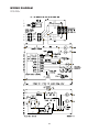
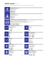
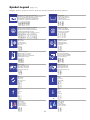
1
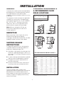
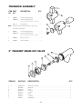
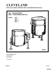
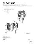
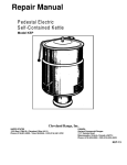
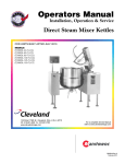
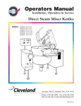
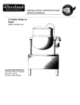
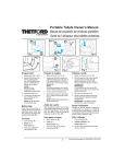
Operators Manual
Installation, Operation & Service
Electric Floor Model Kettles
For units built after August 1999
MODELS:
KEL-25, KEL-30, KEL-40, KEL-40-SH, KEL-60, KEL-80, KEL-100
KEL-25-T, KEL-40-T, KEL-60-T, KEL-80-T, KEL-100-T
KEL-40-SH, KEL-40-TSH, KEL-60-SH, KEL-60-TSH
1333 East 179th St., Cleveland, Ohio, U.S.A. 44110
Enodis
Phone: (216) 481-4900 Fax: (216) 481-3782
Visit our web site at www.clevelandrange.com
SE95036 Rev. 2
TABLE OF CONTENTS
Installation
General . . . . . . . . . . . . . . . . . . . . . . . . . . . . . . . . . . . . . . . . . . . . 1
Inspection . . . . . . . . . . . . . . . . . . . . . . . . . . . . . . . . . . . . . . . . . . . 1
Shipping Damage Instructions . . . . . . . . . . . . . . . . . . . . . . . . . . . 1
Installation . . . . . . . . . . . . . . . . . . . . . . . . . . . . . . . . . . . . . . . . . . 1
Clearance Requirements . . . . . . . . . . . . . . . . . . . . . . . . . . . . . . . . 1
Recommended Floor Drain Locations. . . . . . . . . . . . . . . . . . . . . . 1
Recommended Floor Drain Detail . . . . . . . . . . . . . . . . . . . . . . . . 2
Assembly . . . . . . . . . . . . . . . . . . . . . . . . . . . . . . . . . . . . . . . . . . . 2
Wire Connection . . . . . . . . . . . . . . . . . . . . . . . . . . . . . . . . . . . . . . 2
Water . . . . . . . . . . . . . . . . . . . . . . . . . . . . . . . . . . . . . . . . . . . . . . 2
Installation Checks . . . . . . . . . . . . . . . . . . . . . . . . . . . . . . . . . . . . 3
Cleaning. . . . . . . . . . . . . . . . . . . . . . . . . . . . . . . . . . . . . . . . . . . . 3
Operating Instructions
General Parts Drawing . . . . . . . . . . . . . . . . . . . . . . . . . . . . . . . . 4
Operating the Kettle . . . . . . . . . . . . . . . . . . . . . . . . . . . . . . . . . . . 5
Approximate Boiling Times . . . . . . . . . . . . . . . . . . . . . . . . . . . . . . 5
Cleaning Instructions
Care & Cleaning . . . . . . . . . . . . . . . . . . . . . . . . . . . . . . . . . . . . . 6
Service Parts
Warranty. . . . . . . . . . . . . . . . . . . . . . . . . . . . . . . . . . . . . . . . . . . . 7
Faucet Assembly. . . . . . . . . . . . . . . . . . . . . . . . . . . . . . . . . . . . . . 7
Hinge Assembly . . . . . . . . . . . . . . . . . . . . . . . . . . . . . . . . . . . . . . 8
Kettle Bottom & Side . . . . . . . . . . . . . . . . . . . . . . . . . . . . . . . . 9-10
Control Console Components - Hand Tilt. . . . . . . . . . . . . . . . 11-12
Control Console Components - Power Tilt . . . . . . . . . . . . . . . 13-14
Trunnion Assembly . . . . . . . . . . . . . . . . . . . . . . . . . . . . . . . . . . . 15
2" Tangent Draw-Off Valve . . . . . . . . . . . . . . . . . . . . . . . . . . . . . 15
Spare Parts List . . . . . . . . . . . . . . . . . . . . . . . . . . . . . . . . . . . . . 16
Maintenance
Inspection & Maintenance Check List. . . . . . . . . . . . . . . . . . . . . 17
Calibrating Procedure . . . . . . . . . . . . . . . . . . . . . . . . . . . . . . . . 18
Pressure Relief Valve Periodic Testing Procedure . . . . . . . . . . . . 18
Reservoir Fill Procedures . . . . . . . . . . . . . . . . . . . . . . . . . . . . . . 19
Kettle Venting Instructions . . . . . . . . . . . . . . . . . . . . . . . . . . . . . 19
Vacuum Leak Test Procedure . . . . . . . . . . . . . . . . . . . . . . . . . . . 20
Repairing Leaks in Steam Jacketed Kettle Fittings . . . . . . . . . . . 20
Lubrication Procedure . . . . . . . . . . . . . . . . . . . . . . . . . . . . . . . . 20
Hinge Adjustment Instruction . . . . . . . . . . . . . . . . . . . . . . . . . . . 20
Diagnostic Guide. . . . . . . . . . . . . . . . . . . . . . . . . . . . . . . . . . 21-23
Wiring Diagrams . . . . . . . . . . . . . . . . . . . . . . . . . . . . . . . . . . 24-25
Symbol Legend
. . . . . . . . . . . . . . . . . . . . . . . . . . . . . . . . . . . . . . . . . . . . . . . 26-27
INSTALLATION
GENERAL
CLEARANCE REQUIREMENTS
& RECOMMENDED FLOOR
DRAIN LOCATIONS
Installation of the kettle must be accomplished by
qualified electrical installation personnel working
to all applicable local and national codes.
Improper installation of product could cause injury
or damage.
Clearance Requirements
This equipment is built to comply with applicable
standards for manufacturers. Included among
those approval agencies are: UL, NSF, ASME/Ntl.
Bd., CSA, CGA, ETL, and others. Many local
codes exist, and it is the responsibility of the
owner/installer to comply with these codes.
Back
Left Side
Right Side *
0
0
12'
* Minimum recommended
clearance for service
Note: Maximum voltage for LVD (low volt
directive for Europe) to be 440 volts for CE
marked appliances.
2" Tangent
Draw-Off
Valve
2" Tangent
Draw-Off
Valve
INSPECTION
RECOMMENDED
FLOOR DRAIN
RECOMMENDED
FLOOR DRAIN
Before unpacking visually inspect the unit for
evidence of damage during shipping.
If damage is noticed, do not unpack the unit, follow
Shipping Damage Instructions shown below.
A
A
B
B
SHIPPING DAMAGE
INSTRUCTIONS
RECOMMENDED
FLOOR DRAIN
RECOMMENDED
FLOOR DRAIN
12" x 12"
C
If shipping damage to the unit is discovered or
suspected, observe the following guidelines in
preparing a shipping damage claim.
C
D
D
Tilting
Models
1. Write down a description of the damage or the
reason for suspecting damage as soon as it is
discovered. This will help in filling out the claim
forms later.
Stationary
Models
Recommended Floor Drain Locations **
Model #
A
B
C
D
2. As soon as damage is discovered or suspected,
notify the carrier that delivered the shipment.
KEL-25
22 3/8”
34”
5 1/4”
11 1/4”
KEL-30
25 3/8”
37”
6 3/4”
12 3/4”
3. Arrange for the carrier's representative to
examine the damage.
KEL-40
28 5/8”
40”
7 3/4”
13 3/4”
KEL-40-SH
32 1/2”
44”
9 1/2”
15 1/2”
4. Fill out all carrier claims forms and have the
examining carrier sign and date each form.
KEL-60
32 1/2”
44”
9 1/2”
15 1/2”
KEL-80
35 7/8”
47”
11 1/4”
17 1/4”
KEL-100
38 3/8”
50”
12 1/2”
18 1/2”
KEL-25-T
22 1/4”
51 3/4”
4
24”
INSTALLATION
The first installation step is to refer to the
Specification Sheets or Specification Drawings for
detailed clearance and drain requirements in
order to determine the location of the kettle. Next,
carefully cut open the shipping carton for easy
removal of the kettle.
KEL-40-T
26
56
5 1/2”
28 1/2”
KEL-60-T
29 3/4”
62 1/2”
5 1/2”
31”
KEL-80-T
30 1/2”
65 3/8”
5 1/2”
35 1/2”
KEL-100-T
34 1/8”
69 1/4”
4”
40 1/2”
**
1
Above dimensions apply to standard 2" Tangent Draw-Off Valve
only. For other valves consult factory.
RED
YELLOW
BLACK
4" MINIMUM,
6" RECOMMENDED
RED
BLACK
SINGLE
PHASE
BLUE
RED
THREE
PHASE
BLACK
RECOMMENDED
FLOOR
FLOOR SLOPE
DRAIN
1" IN 4'
BLUE
Note: Maximum voltage for LVD (low voltage
directive for Europe) to be 440 volts for CE
marked appliances.
RECOMMENDED FLOOR
DRAIN DETAIL
RED
YELLOW
BLACK
PIPE DRAIN
RECOMMENDED
MINIMUM VALVE
SIZE PLUS 1"
L1 L2 L3
L1
L2
The kettle is wired for 3-phase operation at the
factory. For single phase operation, rewire the
terminal block to that shown in the above diagram.
ASSEMBLY
Note: Ensure main power is turned off before
connecting wires.
FLANGED
FOOT (5" DIA)
3 1/8"
Stationary Models
Remove the screws securing the dome-shaped
service cover underneath the kettle and remove
the cover. A wiring diagram is affixed to the inside
of cover. Fasten permanent copper wiring to the
three-connection terminal block, Be sure to
connect ground wire to the separate ground
terminal connector (ground lug). Slide the cover's
slot over the wiring and secure the cover to kettle
with the screws.
(3) 7/16" DIA.
HOLES
Flanged Foot Detail
Position the kettle in it's permanent location, and
level the kettle by turning the adjustable flanged
feet. Once positioned and leveled, permanently
secure the kettle's flanged feet to the floor using
5/16" lag bolts and floor anchors (supplied by the
installer). There are three bolts required to secure
each of the flanged feet.
Tilting Models
First remove the handwheel by loosening the allen
screw. Then remove the two screws at the front
and rear of the console cover and remove the
cover. A wiring diagram is affixed to the underside
of the console cover. Feed permanent copper
wiring through the cut-out in the bottom of the
console, and fasten to the three-connection
terminal block. Be sure to connect the ground
terminal connector (ground lug). Replace the
console cover and handwheel.
WIRE CONNECTION
Install in accordance with local codes and/or the
National Electric Code ANSI/NFPA No. 70-1990
(USA) or the Canadian Electric Code CSA
Standard C22.1 (Canada). A separate fused
disconnect switch must be supplied and installed.
The kettle must be electrically grounded by the
installer.
WATER
The sealed jacket of the electric kettle is
precharged with the correct amount of a waterbased formula, and therefore, no water connection
is required to the kettle jacket. The kettle can be
equipped with optional hot and cold water taps,
the taps require 1/2" copper tubing as supply
lines.
The electrical supply must match the power
requirements specified on the kettle's rating plate.
The copper wiring must be adequate to carry the
required current at the rated voltage. Refer to
specification sheet for all electrical specifications.
2
INSTALLATION CHECKS
when the kettle is upright. If the red light remains
lit in the upright position, it indicates a low water
condition, and water must be added to the
reservoir before the kettle can be operated.
Refer to the Reservoir Fill Procedures on page
19 of this manual.
Although the kettle has been thoroughly tested
before leaving the factory, the installer is
responsible for ensuring the proper operation of
kettle once installed.
6. Turn the ON/OFF Switch/Solid State Temperature
Control (1) to "10" (Max.) and allow the kettle to
preheat. The green light should remain on until
the set temperature (260°F/127°C) is reached.
Then the green light will cycle ON and OFF,
indicating the element is cycling ON and OFF to
maintain temperature. Fill the kettle with cold
water to the steam jacket’s welded seam. Refer
to the Temperature Range Chart on page 5 for
the time required to bring the water to a boil.
Visual Checks
1. Check Tilting (tilting kettles):
A/ Gearbox tilts kettle smoothly and freely.
2. Insure there are:
A/ Three lag bolts securely holding each foot
B/ The bottom cover (stationary kettles) is in
place and held with a nut.
C/ The console cover (tilting kettles) is in place
and held with a screw.
7. When all testing is complete, empty the kettle
and turn the ON/OFF Switch/Solid State
Temperature Control (1) to the “OFF” position.
Performance Checks
1. Supply power to the kettle by placing the
fused disconnect switch to the "ON" position.
CLEANING
150
250
20
30
10
300
40
0
IR
NT A
VE
0
After installation the kettle must be thoroughly
cleaned and sanitized prior to cooking. See
complete cleaning instructions on page 6 of this
manual.
200
100
50
50
60
psi
350
400
kPa
2. Before turning the kettle on, read the
Vacuum/Pressure Gauge (4). The gauge's
needle should be in the green zone. If the
needle is in the "VENT AIR" zone, follow Kettle
Venting Procedure on page 19 of this manual.
3. Turn the kettle's ON/OFF Switch/Solid State
Temperature Control (1) to "1" (Min.). The Heat
Indicator Light (Green) (2) should remain lit,
indicating the element is on, until the set
temperature is reached (130°F/54°C). Then the
green light will cycle on and off, indicating the
element is cycling on and off to maintain
temperature.
4. Tilt the kettle forward (tilting models only). The
Low Water Indicator Light (Red) (3) should be lit
when the kettle is in a tilted position. This light
indicates that the element has automatically
been shut off by the kettle's safety circuit. This is
a normal condition when the kettle is in a tilted
position.
5. Raise the kettle to the upright position. The Low
Water Indicator Light (Red) (3) should go out
3
OPERATING INSTRUCTIONS
CONTROL PANEL
6
5
7
4
8
3
9
3.
2
10
1
OFF
1.
4.
5.
KE95555-2-A
4.
5.
2.
6.
8.
8.
CONTROL PANEL
TILTING KETTLE
STATIONARY KETTLE
General Parts Drawing
ITEM #
DESCRIPTION
FUNCTION
1.
On-Off Switch/Solid State
Temperature Control
Turns kettle ON/OFF and allows the operator to adjust the kettle
temperature in increments from 1 (Min.) to 10 (Max.).
(see Temperature Range Chart in the Operating Instructions
section on page 5 of this manual).
2.
Heat Indicator Light (Green)
When lit, indicates that the kettle element is on.
Cycles ON-OFF with element.
3.
Low Water Indicator Light (Red)
When lit, indicates that the kettle is low on water and will not operate
in this condition (see Reservoir Fill Procedures on page 19 of this
manual).
4.
Vacuum/Pressure Gauge
Indicate steam pressure in PSI inside steam jacket as well as
vacuum in inches of mercury.
5.
Pressure Relief Valve
(not shown)
This valve is used to vent the kettle and in the unlikely event there is
an excess steam build-up in the jacket, this valve opens
automatically to relieve this pressure.
6.
Tilt Wheel
Used for tilting the kettle up or down. Some units have an optional
Power Tilt Control Switch located in the same position.
7.
Power Tilt Control Switch
(not shown)
Used for tilting the kettle up or down.
8.
Tangent Draw-Off Valve
Used for draining product or wash water from kettle. It is supplied as
standard equipment on stationary kettles and is optional on tilting kettles.
4
OPERATING THE KETTLE
4. Place food product into the kettle. The Heat
Indicator Light (Green) (2) will cycle on and
off indicating the elements are cycling on and
off to maintain the set temperature.
DO NOT LEAN ON OR PLACE OBJECTS ON
KETTLE LIP. SERIOUS INJURY COULD RESULT
IF KETTLE TIPPED OVER, SPILLING HOT
CONTENTS.
NOTE: Do not fill kettle above
recommended level marked on
outside of kettle.
1. Before turning kettle on, read the
Vacuum/Pressure Gauge (4). The gauges
needle should be in the green zone. If the
needle is in the " VENT AIR " zone, refer to the
Kettle Venting Instructions (page 19). Any air
that may be present will increase cooking
times. Once heated, the kettle's normal
maximum operating pressure is approximately
10-12 psi, while cooking a water base product.
NOTE: The Low Water Indicator Light (Red) (3)
should not be lit during kettle operation. This light
indicates that the elements have been
automatically shut off by the kettle's safety circuit.
It is normal for the red light to come on when the
kettle is in a tilted position. However, the kettle
cannot be operated when the red light remains lit
while the kettle is in the upright position. This
indicates a low water condition, and water must
be added to the reservoir. Refer to Reservoir Fill
Procedures on page 19 of this manual for details.
2. Ensure that the electrical service to the kettle
is turned on at the fused disconnect switch.
Temperature
Control
Setting
Approximate
Product Temperature
°F
°C
1. (Min.)
130
54
2.
145
63
3.
160
71
4.
170
77
5.
185
85
6.
195
91
7.
210
99
8.
230
110
9.
245
118
10. (Max.)
260
127
5. When cooking is completed place ON/OFF
Switch/Solid State Temperature Control (1) to
the "OFF' position.
6. Pour the contents of the kettle into an
appropriate container by tilting the kettle
forward. Care should be taken to pour slowly
enough to avoid splashing off the product.
NOTE: As with cleaning food soil from any
cookware, an important part of kettle cleaning is to
prevent food from drying on. For this reason, cleaning
should be completed immediately after cooked foods
are removed. Refer to the Cleaning Instructions (page
6) for detailed kettle washing procedures.
APPROXIMATE BOILING
TIMES
NOTE: Certain combinations of ingredients will
result in temperature variations
Temperature Range Chart
Times in Minutes
Gals.
3. Preheat the kettle by turning the ON/OFF
Switch/Solid State Temperature Control (1) to
the desired temperature setting (see above
"Temperature Range Chart"). The Heat
Indicator Light (Green) (2) will remain lit,
indicating the burner is lit, until the
temperature setting is reached. When the
green light goes off, the heaters are off, and
preheating is complete.
25
40
60
80
100
Ltrs.
95
150
225
300
375
Standard Wattage
High Wattage*
208V
240V
480V
208V
240V
480V
60
60
100
130
160
45
50
75
100
120
60
75
75
100
120
40
40
50
65
80
30
30
40
50
60
30
30
40
50
60
*High Wattage is only available with 3 phase units.
The accompanying chart shows approximate
times required for electric kettles of various
capacities to boil water. The ON/OFF Switch/Solid
State Temperature Control (1) must be set at "10"
(Max.) throughout the heatup period. Water will
boil about 1/3 faster if the kettle is filled only to the
outer steam jacket's welded seam, resulting in a
kettle filled to 2/3 capacity.
NOTE: When cooking egg and milk products, the
kettle should not be preheated, as products of this
nature adhere to hot cooking surfaces. These
types of food should be placed in the kettle before
heating is begun.
5
CLEANING INSTRUCTIONS
CARE AND CLEANING
c) In a sink, wash and rinse the inside of the
valve body using a nylon brush.
Your kettle must be cleaned regularly to maintain
its fast, efficient cooking performance, and to
ensure its continued safe, reliable operation.
d) Reassemble the draw-off valve by
reversing the procedure for disassembly.
The valve's hex nut should be hand tight
only.
WARNING: Do not use
chloride base detergents.
There is a growing number of
non-chloride cleaners
available. If unsure of the
cleaners chlorine content
consult the supplier. Also
avoid cleaners containing
Chloride Cleaners
quaternary salt as they can
cause the stainless steel to pit and rust.
6. Rinse kettle interior thoroughly, then drain the
rinse water. Do not leave water sitting in unit
when not in use.
7. Using mild soapy water and a damp sponge,
wash the exterior of the kettle, rinse, and dry.
NOTE: For more difficult
cleaning applications one of
the following can be used:
alcohol, baking soda, vinegar,
or a solution of ammonia in
water.
WARNING: If any gaskets or seals are found
defective, replace or repair immediately. (See
Service Parts Drawings for part identification.)
1. Place the kettle's On-Off Switch/Solid State
Temperature Control (1) to the "OFF" position.
Steel Pads
2. Prepare a warm water and mild detergent
solution in the kettle.
Avoid the use of chloride
cleansers, which may damage
the kettle's stainless steel
surface.
WARNING: Steel wool should never be used for
cleaning the cooking chamber of the kettle.
Particles of steel wool become embedded in the
cooking surface and rust, which may corrode the
stainless steel.
3. Remove food soil inside the kettle using a
nylon brush.
WARNING: Do not use a
metal bristle brush or scraper,
as this may permanently
damage the kettle's stainless
steel surface.
NOTE: Unit should not be cleaned with a water jet.
8. Leave the cover off when the kettle is not in
use.
Wire Brush & Scrapers
4. Loosen food which is stuck to the kettle by
allowing it to soak at a low temperature
setting.
RECOMMENDED CLEANERS FOR SPECIFIC
SITUATIONS
5. If the kettle is equipped with a draw-off valve,
it should be cleaned as follows:
a) Remove drain screen from bottom of
kettle. Thoroughly wash and rinse the
screen either in a sink or a dishwasher,
then replace it into the kettle.
b) Disassemble the draw-off valve first by
turning the valve knob counter-clockwise,
then turning the large hex nut counterclockwise until the valve stem is free of
the valve body.
6
Job
Cleaning Agent
Comments
Routine Cleaning
Soap, Ammonia
Detergent, Medallion
Apply with cloth or
sponge
Fingerprints
& Smears
Arcal 20, Lac-O-Nu
Ecoshine
Provides barrier film
Stubborn Stains
& Discolouration
Cameo, Talc, Zud
First Impression
Rub in direction
of polish lines
Grease & Fatty Acids,
Blood, Burnt-On Foods
Easy-Off, De-Grease It
Oven Aid
Excellent removal
on all finishes
Grease & Oil
Any good commercial
detergent
Apply with sponge
or cloth
Restoration/
Passivation
Benefit, Super Sheen
SERVICE PARTS
WARRANTY
Our Company supports a worldwide network of Maintenance and Repair Centers. Contact your nearest
Maintenance and Repair Centre for replacement parts, service, or information regarding the proper
maintenance and repair of your cooking equipment
In order to preserve the various agency safety certification (UL, NSF, ASME/Ntl. Bd., etc.), only factorysupplied replacement parts should be used. The use of other than factory supplied replacement parts will
void warranty.
FAUCET ASSEMBLY
1
2
1
ITEM PART
NO. NO.
DESCRIPTION
QTY.
3
4
2
5
3
6
1.
KE50825-5
KE50825-3
KE50825-2
2.
FA95022
4
3/4" Spout . . . . . . . . . . . . . . . . . . . .1
(KEL-25/30/40/60/80/100 & 40-SH)
3/4" Spout (KEL-25-T) . . . . . . . . . . . .1
3/4" Spout (KEL-40/60/80/100-T) . . . .1
6
10
7
Retaining Ring . . . . . . . . . . . . . . . . . .1
11
9
8
3.
FA05002-19 "O" Ring . . . . . . . . . . . . . . . . . . . . . . .1
4.
KE51736
Long Faucet Nut . . . . . . . . . . . . . . . .1
5.
SE50020
Hot Water Stem Assembly . . . . . . . . .1
(Double Pantry only)
12
13
10
11
12
6.
SE50021
Cold Water Stem Assembly . . . . . . . .1
7.
KE51401
Single Pantry Body . . . . . . . . . . . . . .1
(c/w Item No. 6)
8.
KE50335
Adapter Washer . . . . . . . . . . . . . . . .1
(Single Pantry only)
9.
KE51403
Double Pantry Body . . . . . . . . . . . . .1
(c/w Item No. 5&6)
10.
KE54159
Faucet Mounting Bracket . . . . . . . . . .1
11.
FA11258
Hex Cap Screw . . . . . . . . . . . . . . . . .2
12.
FA30505
Washer . . . . . . . . . . . . . . . . . . . . . . .2
13.
FA21008
Hex Nut . . . . . . . . . . . . . . . . . . . . . . .2
14.
SE50447
Washer Horseshoe . . . . . . . . . . . . . .1
7
13
14
HINGE ASSEMBLY
9
4
7
11
8
6
10
1
9
5
12
ITEM NO.
1. - 11
PART NO.
DESCRIPTION
13
2
3
QTY.
KE50597-1
Hinge Assembly - up to 40 gal. . . . . . . . . . . . . . . . . . . . . . . . . . . . . . . . . . .1
KE50597-2
60 & 80 gal. . . . . . . . . . . . . . . . . . . . . . . . . . . . . . . . . . .1
KE50597-3
100 gal. & up . . . . . . . . . . . . . . . . . . . . . . . . . . . . . . . . . .1
1.
KE50882
Hinge Base . . . . . . . . . . . . . . . . . . . . . . . . . . . . . . . . . . . . . . . . . . . . . . . . . .1
2.
KE51217
Hinge Cylinder . . . . . . . . . . . . . . . . . . . . . . . . . . . . . . . . . . . . . . . . . . . . . . . .1
3.
KE50121-2
Torsion Spring -
KE50121-1
4.
KE50823-1
KE50823-2
up to 40 gal. . . . . . . . . . . . . . . . . . . . . . . . . . . . . . . . . . .1
60 gal & up . . . . . . . . . . . . . . . . . . . . . . . . . . . . . . . . . . .1
Hinge Pin -
up to 80 gal. . . . . . . . . . . . . . . . . . . . . . . . . . . . . . . . . . .1
100 gal. & up . . . . . . . . . . . . . . . . . . . . . . . . . . . . . . . . . .1
5.
KE50824
Hinge Bearing . . . . . . . . . . . . . . . . . . . . . . . . . . . . . . . . . . . . . . . . . . . . . . . .1
6.
KE50819-1
Hinge End Piece . . . . . . . . . . . . . . . . . . . . . . . . . . . . . . . . . . . . . . . . . . . . . . .1
7.
KE50620
Hinge Insert . . . . . . . . . . . . . . . . . . . . . . . . . . . . . . . . . . . . . . . . . . . . . . . . . .1
8.
KE50819
Hinge End Piece . . . . . . . . . . . . . . . . . . . . . . . . . . . . . . . . . . . . . . . . . . . . . . .1
9.
FA11284
Screw, Socket Head . . . . . . . . . . . . . . . . . . . . . . . . . . . . . . . . . . . . . . . . . . . .4
10.
FA11507
Cutting Screw, . . . . . . . . . . . . . . . . . . . . . . . . . . . . . . . . . . . . . . . . . . . . . . . .2
11.
SK50418
Plug Button . . . . . . . . . . . . . . . . . . . . . . . . . . . . . . . . . . . . . . . . . . . . . . . . . . .1
12.
KE50151-E
Knob . . . . . . . . . . . . . . . . . . . . . . . . . . . . . . . . . . . . . . . . . . . . . . . . . . . . . . .1
13.
Cover Handle (specify model) . . . . . . . . . . . . . . . . . . . . . . . . . . . . . . . . . . . .1
8
KETTLE BOTTOM & SIDE
11
2
27
28
1
3
4
6
5
10
Element
Terminals
20
18 32
21
22
9
25
26
8
7
24
23
19
12
14
16
15 13
17
9
7
KETTLE BOTTOM & SIDE
ITEM NO.
PART NO.
DESCRIPTION
1.
KE50556-1
Probe, Water Level . . . . . . . . . . . . . . . . . . . . . . . . . . . . . . . . . . . . . . . . . . . . .1
2.
QTY.
KE51723
Safety Valve, 50 PSI, 1/2" (for 25-80 gallon kettles) . . . . . . . . . . . . . . . . . . . . .1
KE51721
Safety Valve, 35 PSI, 1/2", (for 100 gallon kettles) . . . . . . . . . . . . . . . . . . . . . .1
3.
KE51226
Wire Connector Terminal . . . . . . . . . . . . . . . . . . . . . . . . . . . . . . . . . . . . . . . .10
4.
KE51225
Edge Connector . . . . . . . . . . . . . . . . . . . . . . . . . . . . . . . . . . . . . . . . . . . . . . .1
5.
KE00458
Solid State Control Box . . . . . . . . . . . . . . . . . . . . . . . . . . . . . . . . . . . . . . . . . .1
6.
KE50753-7
Relay, 12 VDC . . . . . . . . . . . . . . . . . . . . . . . . . . . . . . . . . . . . . . . . . . . . . . . .1
7.
KE54761
Bracket, Terminal Block . . . . . . . . . . . . . . . . . . . . . . . . . . . . . . . . . . . . . . . . .1
8.
KE50377
Terminal Block Section . . . . . . . . . . . . . . . (Large, White) . . . . . . . . . . . . . . .3
SK50055-1
Terminal Block Section . . . . . . . . . . . . . . . (Small) . . . . . . . . . . . . . . . . . . . .3
KE50376
Terminal Block End Section
SK50054-1
Terminal Block End Section . . . . . . . . . . . . (Small) . . . . . . . . . . . . . . . . . . . .1
SK50054-2
Terminal Block End Barrier . . . . . . . . . . . . . . . . . . . . . . . . . . . . . . . . . . . . . . .1
9.
10.
. . . . . . . . . . . (Large, White) . . . . . . . . . . . . . . .1
KE53838-11
Transformer, 380-415 to 120-220V . . . . . . . . . . . . . . . . . . . . . . . . . . . . . . . . .1
KE53838-12
Transformer, 440-480 to 240V . . . . . . . . . . . . . . . . . . . . . . . . . . . . . . . . . . . . .1
KE53838-13
Transformer, 600 to 240V . . . . . . . . . . . . . . . . . . . . . . . . . . . . . . . . . . . . . . . .1
11.
KE50429-3
Pressure Gauge . . . . . . . . . . . . . . . . . . . . . . . . . . . . . . . . . . . . . . . . . . . . . . .1
12.
KE50568-1
L.E.D., Green . . . . . . . . . . . . . . . . . . . . . . . . . . . . . . . . . . . . . . . . . . . . . . . . .1
13.
KE50567-1
L.E.D., Red . . . . . . . . . . . . . . . . . . . . . . . . . . . . . . . . . . . . . . . . . . . . . . . . . . .1
14.
SE00114
Potentiometer with ON/OFF Switch, c/w Item #15 . . . . . . . . . . . . . . . . . . . . . .1
15.
KE51005
Rubber Boot
16.
KE50569-1
Knob, Potentiometer . . . . . . . . . . . . . . . . . . . . . . . . . . . . . . . . . . . . . . . . . . . .1
17.
KE50558
Safety Thermostat (140° C) . . . . . . . . . . . . . . . . . . . . . . . . . . . . . . . . . . . . . . .1
. . . . . . . . . . . . . . . . . . . . . . . . . . . . . . . . . . . . . . . . . . . . . . . . .1
18.
KE50515
Thermistor . . . . . . . . . . . . . . . . . . . . . . . . . . . . . . . . . . . . . . . . . . . . . . . . . . .1
19.
KE50750-3
Contactor, 208/240V, 40 Amp. (standard kettles) . . . . . . . . . . . . . . . . . . . . . . .2
KE50750-4
Contactor, 208/240V, 50 Amp. (special high wattage kettles - 6 elements) . . .2
KE50750-5
Contactor, 208/240V, 60 Amp. (special high wattage kettles - 6 elements) . . .2
20.
KE51139-1
Fuse Holder . . . . . . . . . . . . . . . . . . . . . . . . . . . . . . . . . . . . . . . . . . . . . . . . . .1
21.
KE52936-1
Fuse, 1/2 amp (used on 380 to 600V units) . . . . . . . . . . . . . . . . . . . . . . . . . . .1
22.
KE54833-3
Snap-In Bushing, .875" . . . . . . . . . . . . . . . . . . . . . . . . . . . . . . . . . . . . . . . . . .1
23.
KE54833-4
Snap-In Bushing 1.093" . . . . . . . . . . . . . . . . . . . . . . . . . . . . . . . . . . . . . . . . .1
24.
KE50473
Ground . . . . . . . . . . . . . . . . . . . . . . . . . . . . . . . . . . . . . . . . . . . . . . . . . . . . . .1
25.
KE53838-19
Transformer, 120 to 16V . . . . . . . . . . . . . . . . . . . . . . . . . . . . . . . . . . . . . . . . .1
KE53838-21
Transformer, 240 to 16V . . . . . . . . . . . . . . . . . . . . . . . . . . . . . . . . . . . . . . . . .1
KE50391
Bracket, Electrical Entry, 1 3/8" hole . . . . . . . . . . . . . . . . . . . . . . . . . . . . . . . .1
26.
KE50392
Bracket, Electrical Entry, 1 3/4" hole . . . . . . . . . . . . . . . . . . . . . . . . . . . . . . . .1
27.
KE54852-1
Guard Bracket, Pressure Relief Valve . . . . . . . . . . . . . . . . . . . . . . . . . . . . . . .1
28.
FA11145
Screw, 10-32 x 3/8" SS . . . . . . . . . . . . . . . . . . . . . . . . . . . . . . . . . . . . . . . . . .2
10
CONTROL CONSOLE COMPONENTS - HAND TILT
11
KEL-T (hand tilt) A
CONTROL CONSOLE COMPONENTS - HAND TILT
ITEM NO.
PART NO.
DESCRIPTION
1.
FA11134
Screw, 10-24 x 3/8" SS . . . . . . . . . . . . . . . . . . . . . . . . . . . . . . . . . . . . . . . . . .2
2.
KE50325
Gear Box Lid . . . . . . . . . . . . . . . . . . . . . . . . . . . . . . . . . . . . . . . . . . . . . . . . .1
3.
FA95008
Locknut, 3/4-16 . . . . . . . . . . . . . . . . . . . . . . . . . . . . . . . . . . . . . . . . . . . . . . . .2
4.
FA30088
Washer, 1 1/2" 0.D. x 13/16" I.D. x .125 "W. . . . . . . . . . . . . . . . . . . . . . . . . . . .1
5.
SE00036
Thrust Bearing Assembly and Spacer . . . . . . . . . . . . . . . . . . . . . . . . . . . . . . .2
6.
KE50752
Transformer, 240/16V . . . . . . . . . . . . . . . . . . . . . . . . . . . . . . . . . . . . . . . . . . .1
7.
KE50315
Worm . . . . . . . . . . . . . . . . . . . . . . . . . . . . . . . . . . . . . . . . . . . . . . . . . . . . . . .1
8.
FA95005
Tension Pin . . . . . . . . . . . . . . . . . . . . . . . . . . . . . . . . . . . . . . . . . . . . . . . . . . .1
9.
KE50375
Tilt Shaft . . . . . . . . . . . . . . . . . . . . . . . . . . . . . . . . . . . . . . . . . . . . . . . . . . . . .1
10.
FA19505
Set Screw, hand wheel . . . . . . . . . . . . . . . . . . . . . . . . . . . . . . . . . . . . . . . . . .1
11.
KE00508
Hand Wheel . . . . . . . . . . . . . . . . . . . . . . . . . . . . . . . . . . . . . . . . . . . . . . . . . .1
12.
FA95007
Retaining Ring (25-40 gallon) . . . . . . . . . . . . . . . . . . . . . . . . . . . . . . . . . . . . .2
FA95050
Retaining Ring (60 gallon & up) . . . . . . . . . . . . . . . . . . . . . . . . . . . . . . . . . . .2
KE00151
Segment Gear (25-40 gallon) . . . . . . . . . . . . . . . . . . . . . . . . . . . . . . . . . . . . .1
KE52833
Segment Gear (60 gallon & up) . . . . . . . . . . . . . . . . . . . . . . . . . . . . . . . . . . .1
FA95048
Woodruff Key (25-40 gallon) . . . . . . . . . . . . . . . . . . . . . . . . . . . . . . . . . . . . . .1
FA95051
Woodruff Key (60 gallon & up) . . . . . . . . . . . . . . . . . . . . . . . . . . . . . . . . . . . .1
KE51711
Roller Bearing, trunnion (25-40 gallon) . . . . . . . . . . . . . . . . . . . . . . . . . . . . . .2
KE517111
Roller Bearing, trunnion (60 gallon & up) . . . . . . . . . . . . . . . . . . . . . . . . . . . .2
KE50377
Terminal Block Section (large, white) . . . . . . . . . . . . . . . . . . . . . . . . . . . . . . .3
SK50055
Terminal Block Section (small, black) . . . . . . . . . . . . . . . . . . . . . . . . . . . . . . .3
KE50376
Terminal Block End Section (large, white) . . . . . . . . . . . . . . . . . . . . . . . . . . . .1
SK50054
Terminal Block End Section (small, black) . . . . . . . . . . . . . . . . . . . . . . . . . . . .1
18.
T40226
Bearing Assembly . . . . . . . . . . . . . . . . . . . . . . . . . . . . . . . . . . . . . . . . . . . . .1
19.
FA10623
Bolt, 5/16-24 x 1 1/2" . . . . . . . . . . . . . . . . . . . . . . . . . . . . . . . . . . . . . . . . . . . .1
20.
FA20029
Hex Nut, 5/16-24 . . . . . . . . . . . . . . . . . . . . . . . . . . . . . . . . . . . . . . . . . . . . . .1
21.
KE51891
Washer, 1 1/2" 0.D. x 13/16” I.D. x .037" W. . . . . . . . . . . . . . . . . . . . . . . . . . . .2
25.
KE51730
Bearing, tilt shaft . . . . . . . . . . . . . . . . . . . . . . . . . . . . . . . . . . . . . . . . . . . . . . .1
13.
14.
15.
16.
17.
QTY.
12
KEL-T (hand tilt) B
CONTROL CONSOLE COMPONENTS - POWER TILT
13
KEL-T (power tilt) A
CONTROL CONSOLE COMPONENTS - POWER TILT
ITEM NO.
PART NO.
DESCRIPTION
1.
2.
3.
4.
KE503252
FA11134
KE50577
KE51224
KE52386
KE50583
KE50582
KE50377
SK50055
KE50376
SK50054
FA95008
FA30088
SE00036
FA95005
KE50581
KE51011
KE51009
KE51010
KE50752
FA95007
FA95050
FA95048
FA95051
KE50580
KE51007
FA00012
KE00151
KE52833
KE50315
KE50441
FA11081
KE51711
KE517111
KE51731
FA10623
FA20229
T40226
KE51891
FA95037
FA95014
KE50579
Gear Box Lid . . . . . . . . . . . . . . . . . . . . . .
Screw, 10-24 x 3/8" S.S. . . . . . . . . . . . . . .
Motor . . . . . . . . . . . . . . . . . . . . . . . . . . . .
Transformer, 208/120V (HG3J) . . . . . . . . .
Transformer, 220, 240/120V (HG5J) . . . . .
Buna-N Insert . . . . . . . . . . . . . . . . . . . . . .
Coupling . . . . . . . . . . . . . . . . . . . . . . . . .
Terminal Block Section (large, white) . . . .
Terminal Block Section (small, black) . . . .
Terminal Block End Section (large, white) .
Terminal Block End Section (small, black) .
Locknut, 3/4-16 . . . . . . . . . . . . . . . . . . . . .
Washer,1 1/2" 0.D. x 13/16" I.D. x .125" W.
Thrust Bearing Assembly and Spacer . . . .
Tension Pin . . . . . . . . . . . . . . . . . . . . . . . .
Bridge Rectifier . . . . . . . . . . . . . . . . . . . . .
Contact Section . . . . . . . . . . . . . . . . . . . .
Square Spacer Plate . . . . . . . . . . . . . . . . .
Square Actuator . . . . . . . . . . . . . . . . . . . .
Transformer, 240/16V . . . . . . . . . . . . . . . .
Retaining Ring (25-40 gallon) . . . . . . . . . .
Retaining Ring (60 gallon & up) . . . . . . . .
Woodruff Key (25-40 gallon) . . . . . . . . . . .
Woodruff Key (60 gallon & up) . . . . . . . . .
Water Resistant Boot . . . . . . . . . . . . . . . .
Micro Switch . . . . . . . . . . . . . . . . . . . . . . .
"O" Ring, circuit breaker . . . . . . . . . . . . . .
Segment Gear (25-40 gallon) . . . . . . . . . .
Segment Gear (60 gallon & up) . . . . . . . .
Worm . . . . . . . . . . . . . . . . . . . . . . . . . . . .
Tilt Shaft . . . . . . . . . . . . . . . . . . . . . . . . . .
Screw, 8-32 x 1/2", SS . . . . . . . . . . . . . . . .
Roller Bearing, trunnion (25-40 gallon) . . .
Roller Bearing, trunnion (60 gallon & up) .
Bearing, tilt shaft . . . . . . . . . . . . . . . . . . . .
Bolt, 5/16-24 x 1 1/2" . . . . . . . . . . . . . . . .
Hex Nut, 5/16-24 . . . . . . . . . . . . . . . . . . .
Bearing assembly . . . . . . . . . . . . . . . . . . .
Washer, 1 1/2" 0.D. x 13/16" I.D. x .037" W.
Key, 3/16" x 3/16" x 3/4" . . . . . . . . . . . . . .
Key, 3/16" x 3/16" x 1" . . . . . . . . . . . . . . . .
Circuit breaker, 1 amp . . . . . . . . . . . . . . .
5.
6.
7.
8.
9.
10.
11.
12.
13.
14.
15.
16.
17.
18.
19.
20.
22.
23.
24.
25.
26.
27.
28.
29.
30.
31.
32.
33.
37.
38.
39.
QTY.
.
.
.
.
.
.
.
.
.
.
.
.
.
.
.
.
.
.
.
.
.
.
.
.
.
.
.
.
.
.
.
.
.
.
.
.
.
.
.
.
.
.
.
.
.
.
.
.
.
.
.
.
.
.
.
.
.
.
.
.
.
.
.
.
.
.
.
.
.
.
.
.
.
.
.
.
.
.
.
.
.
.
.
.
.
.
.
.
.
.
.
.
.
.
.
.
.
.
.
.
.
.
.
.
.
.
.
.
.
.
.
.
.
.
.
.
.
.
.
.
.
.
.
.
.
.
.
.
.
.
.
.
.
.
.
.
.
.
.
.
.
.
.
.
.
.
.
.
.
.
.
.
.
.
.
.
.
.
.
.
.
.
.
.
.
.
.
.
.
.
.
.
.
.
.
.
.
.
.
.
.
.
.
.
.
.
.
.
.
.
.
.
.
.
.
.
.
.
.
.
.
.
.
.
.
.
.
.
.
.
.
.
.
.
.
.
.
.
.
.
.
.
.
.
.
.
.
.
.
.
.
.
.
.
.
.
.
.
.
.
.
.
.
.
.
.
.
.
.
.
.
.
.
.
.
.
.
.
.
.
.
.
.
.
.
.
.
.
.
.
.
.
.
.
.
.
.
.
.
.
.
.
.
.
.
.
.
.
.
.
.
.
.
.
.
.
.
.
.
.
.
.
.
.
.
.
.
.
.
.
.
.
.
.
.
.
.
.
.
.
.
.
.
.
.
.
.
.
.
.
.
.
.
.
.
.
.
.
.
.
.
.
.
.
.
.
.
.
.
.
.
.
.
.
.
.
.
.
.
.
.
.
.
.
.
.
.
.
.
.
.
.
.
.
.
.
.
.
.
.
.
.
.
.
.
.
.
.
.
.
.
.
.
.
.
.
.
.
.
.
.
.
.
.
.
.
.
.
.
.
.
.
.
.
.
.
.
.
.
.
.
.
.
.
.
.
.
.
.
.
.
.
.
.
.
.
.
.
.
.
.
.
.
.
.
.
.
.
.
.
.
.
.
.
.
.
.
.
.
.
.
.
.
.
.
.
.
.
.
.
.
.
.
.
.
.
.
.
.
.
.
.
.
.
.
.
.
.
.
.
.
.
.
.
.
.
.
.
.
.
.
.
.
.
.
.
.
.
.
.
.
.
.
.
.
.
.
.
.
.
.
.
.
.
.
.
.
.
.
.
.
.
.
.
.
.
.
.
.
.
.
.
.
.
.
.
.
.
.
.
.
.
.
.
.
.
.
.
.
.
.
.
.
.
.
.
.
.
.
.
.
.
.
.
.
.
.
.
.
.
.
.
.
.
.
.
.
.
.
.
.
.
.
.
.
.
.
.
.
.
.
.
.
.
.
.
.
.
.
.
.
.
.
.
.
.
.
.
.
.
.
.
.
.
.
.
.
.
.
.
.
.
.
.
.
.
.
.
.
.
.
.
.
.
.
.
.
.
.
.
.
.
.
.
.
.
.
.
.
.
.
.
.
.
.
.
.
.
.
.
.
.
.
.
.
.
.
.
.
.
.
.
.
.
.
.
.
.
.
.
.
.
.
.
.
.
.
.
.
.
.
.
.
.
.
.
.
.
.
.
.
.
.
.
.
.
.
.
.
.
.
.
.
.
.
.
.
.
.
.
.
.
.
.
.
.
.
.
.
.
.
.
.
.
.
.
.
.
.
.
.
.
.
.
.
.
.
.
.
.
.
.
.
.
.
.
.
.
.
.
.
.
.
.
.
.
.
.
.
.
.
.
.
.
.
.
.
.
.
.
.
.
.
.
.
.
.
.
.
.
.
.
.
.
.
.
.
.
.
.
.
.
.
.
.
.
.
.
.
.
.
.
.
.
.
.
.
.
.
.
.
.
.
.
.
.
.
.
.
.
.
.
.
.
.
.
.
.
.
.
.
.
.
.
.
.
.
.
.
.
.
.
.
.
.
.
.
.
.
.
.
.
.
.
.
.
.
.
.
.
.
.
.
.
.
.
.
.
.
.
.
.
.
.
.
.
.
.
.
.
.
.
.
.
.
.
.
.
.
.
.
.
.
.
.
.
.
.
.
.
.
.
.
.
.
.
.
.
.
.
.
.
.
.
.
.
.
.
.
.
.
.
.
.
.
.
.
.
.
.
.
.
.
.
.
.
.
.
.
.
.
.
.
.
.
.
.
.
.
.
.
.
.
.
.
.
.
.
.
.
.
.
.
.
.
.
.
.
.
.
.
.
.
.
.
.
.
.
.
.
.
.
.
.
.
.
.
.
.
.
.
.
.
.
.
.
.
.
.
.
.
.
.
.
.
.
.
.
.
.
.
.
.
.
.
.
.
.
.
.
.
.
.
.
.
.
.
.
.
.
.
.
.
.
.
.
.
.
.
.
.
.
.
.
.
.
.
.
.
.
.
.
.
.
.
.
.
.
.
.
.
.
.
.
.
.
.
.
.
.
.
.
.1
.1
.1
.1
.1
.1
.2
.3
.3
.1
.1
.2
.1
.2
.1
.1
.6
.1
.1
.1
.1
.1
.1
.1
.1
.2
.1
.1
.1
.1
.1
.4
.2
.2
.1
.1
.1
.1
.2
.1
.1
.1
14
KEL-T (power tilt) B
TRUNNION ASSEMBLY
ITEM PART
NO. NO.
For Spring
Assist Lid Only
DESCRIPTION
QTY.
1
1.
KE00354
Trunnion Bearing Casting . . . . . . . . . . . . .1
KE00354-D
Trunnion Bearing Casting . . . . . . . . . . . . .1
(without roller bearings, used prior to July 1984)
KE51711
Note:
Roller Bearing . . . . . . . . . . . . . . . . . . . . .2
4
2
Units without roller bearings cannot be replaced by
units with roller bearings.
2.
KE00351
3
Trunnion Bearing Casting . . . . . . . . . . . . .1
KE00351-D
Trunnion Bearing Casting . . . . . . . . . . . . .1
(without roller bearings, used prior to July 1984)
3.
KE00349
Bolt, 5/16-18 x 1/2" . . . . . . . . . . . . . . . . . .1
4.
KE50666
Spherical Washer . . . . . . . . . . . . . . . . . . .1
2" TANGENT DRAW-OFF VALVE
7
6
5
4
3
2
1
ITEM NO.
PART NO.
DESCRIPTION
1. - 7.
1.
2.
3.
4.
5.
6.
7.
KE50972-B
FA95049
KE527551
KE52754
KE52753
KE52752
FA00111
KE52751
Draw-Off Assembly
Wing Nut . . . . . . .
Knob . . . . . . . . . .
Hex Nut . . . . . . . .
Retainer . . . . . . . .
Piston . . . . . . . . . .
"O" Ring . . . . . . . .
Valve Body . . . . .
QTY.
.
.
.
.
.
.
.
.
.
.
.
.
.
.
.
.
.
.
.
.
.
.
.
.
.
.
.
.
.
.
.
.
15
.
.
.
.
.
.
.
.
.
.
.
.
.
.
.
.
.
.
.
.
.
.
.
.
.
.
.
.
.
.
.
.
.
.
.
.
.
.
.
.
.
.
.
.
.
.
.
.
.
.
.
.
.
.
.
.
.
.
.
.
.
.
.
.
.
.
.
.
.
.
.
.
.
.
.
.
.
.
.
.
.
.
.
.
.
.
.
.
.
.
.
.
.
.
.
.
.
.
.
.
.
.
.
.
.
.
.
.
.
.
.
.
.
.
.
.
.
.
.
.
.
.
.
.
.
.
.
.
.
.
.
.
.
.
.
.
.
.
.
.
.
.
.
.
.
.
.
.
.
.
.
.
.
.
.
.
.
.
.
.
.
.
.
.
.
.
.
.
.
.
.
.
.
.
.
.
.
.
.
.
.
.
.
.
.
.
.
.
.
.
.
.
.
.
.
.
.
.
.
.
.
.
.
.
.
.
.
.
.
.
.
.
.
.
.
.
.
.
.
.
.
.
.
.
.
.
.
.
.
.
.
.
.
.
.
.
.
.
.
.
.
.
.
.
.
.
.
.
.
.
.
.
.
.
.
.
.
.
.
.
.
.
.
.
.
.
.
.
.
.
.
.
.
.
.
.
.
.
.
.
.
.
.
.
.
.
.
.
.
.
.
.
.
.
.
.
.
.
.
.
.
.
.
.
.
.
.
.
.
.
.
.
.
.
.
.
.
.
.
.
.1
.1
.1
.1
.1
.1
.1
.2
SPARE PARTS LIST
ITEM ON.
DESCRIPTION
QTY.
QTY.
DOMESTIC
OVERSEAS
1
1
Refer to page 9, Kettle Bottom& Side for parts drawing
KE00458
Solid State Control Box
KE50753-7
Relay, 12 VDC
KE50750-5
Contactor, 208/240V, 60 Amp.
(special high wattage kettles - 6 elements)
KE53838-11
Transformer, 380-415 to 120-220V
1
1
2
1
SE00114
Potentiometer with ON/OFF Switch, c/w Rubber Boot
1
1
KE51005
Rubber Boot
1
1
KE50569-1
Knob, Potentiometer
1
1
KE50515
Thermistor
1
KE51005
Rotary Seal
1
KE52936-1
Fuse, 1/2 amp (used on 380 to 600V units)
1
KE53838-19
Transformer, 120 to 16V
1
1
KE53838-21
Transformer, 240 to 16V
1
1
1
1
Refer to page 7, Faucet Assembly for drawing
FA05002-19
"O" Ring for Faucet Spout
16
MAINTENANCE
ALL SERVICE MUST BE PERFORMED BY A QUALIFIED SERVICE TECHNICIAN.
Cleveland Range equipment requires little preventative maintenance. We do however provide the following
chart as a guideline for inspection and maintenance to keep your unit functioning at 100%.
INSPECTION AND MAINTENANCE CHECK LIST
The following check should be completed every six months or more frequently if unit is in a high volume
facility.
WARNING: It is imperative that damaged seals be repaired immediately to prevent equipment failure
and/or damage.
ITEM
CHECK
BOTTOM COVER GASKETS
Check to see both
gaskets are in place
and are not cracked
or split.
Kettle Bottom
Gaskets
CONSOLE COVER
Insure there are two screws firmly holding down the cover. If not replace
screws.
HAND WHEEL
Check hand wheel for tightness. If loose tighten allen screw.
TILTING
(hand tilt models only)
(tilting models only)
PRESSURE GAUGE
Check that kettle tilts smoothly. Grease as described in Lubrication
Procedure (page 20).
Check that the gauge does not have moisture on its inside face.
Replace if moisture is present.
Check that the gauge shows a vacuum (needle is well into the Green
zone) when cold and shows between 25-40 psi when unit is hot. If not
follow Vacuum Leak Test Procedure (page 20).
PRESSURE RELIEF VALVE
Check pressure relief valve as described in Pressure Relief Valve
Testing Procedure (page 18).
TEMPERATURE CHECK
Following Calibrating Procedure (page 18) check the inner kettle
surface temperature with a digital surface thermometer and adjust if
required.
17
CALIBRATING PROCEDURE
DANGER: PRESSURE RELIEF
VALVE WILL EXHAUST HIGH
TEMPERATURE STEAM. CONTACT
WITH SKIN COULD RESULT IN
SERIOUS BURNS. KEEP FACE,
HANDS AND BODY CLEAR OF DISCHARGE.
1.
Insure the unit has a vacuum before you begin
calibrating procedures. If unit requires venting refer
to Kettle Venting Instructions on page 19 of this
manual.
2.
Turn kettle ON and set temperature dial to 10
(Max.).
3.
Allow the unit to cycle twice.
4.
Check temperature of the inner kettle surface with
a digital surface thermometer.
5.
Temperature should be between 260° F and 265° F.
1.
Remove guard bracket from pressure relief
valve/gauge assembly.
6.
Using a screw driver adjust temperature by turning
the potentiometer on the black box. Turn very little.
Turn clockwise to INCREASES and counterclockwise to DECREASE temperature.
2.
With the kettle empty, turn unit ON and set
temperature control to 10 (Max.). Allow the kettle to
heat until the unit cycles off.
7.
Allow the unit to cycle twice.
3.
8.
Check temperature of the inner kettle surface with
a digital surface thermometer.
Switch unit OFF and disconnect main power at
fused disconnect switch.
4.
Stand to the side of the pressure relief valve
discharge tube and pull valve open for a maximum
of one second. Repeat test three to four times. Each
time the mechanism should move freely and be
accompanied by a rapid escape of steam.
5.
Replace guard bracket from pressure relief
valve/gauge assembly.
DANGER: WORKING ON MACHINES
WITH POWER COULD RESULT IN
SEVERE ELECTRICAL SHOCK.
9. Repeat steps 4 through 8 until unit is calibrated.
Pressure Guage
Pressure Relief Valve
Guard Bracket
Pressure Relief Valve/Gauge Assembly Drawing
PRESSURE RELIEF VALVE
PERIODIC TESTING
PROCEDURE
WARNING: IMPROPER REFILLING OF
KETTLE JACKET WILL RESULT IN
IRREVERSIBLE DAMAGE TO UNIT.
If valve appears to be sticking replace pressure relief
valve.
If foreign material is discharged then drain kettle and
replace pressure relief valve.
Most insurance agencies require periodic testing of
pressure relief valves used on pressure vessels. This
procedure will allow you to safely and quickly test your
kettle's pressure relief valve. We recommend this test be
performed twice a year.
See Reservoir Fill Procedure (page 19) for full instructions
on the correct method for refilling kettle jacket.
WARNING: Improper refilling of kettle jacket will result
in irreversible damage to unit.
NOTE: The following instruction is intended for use by
qualified service personnel.
NOTE: Rust inhibitor is purchased locally. Read
directions and do not exceed manufacturer's
recommendation (excessive rust inhibitor can also
cause solidification).
WARNING: Kettle surface will be hot and steam will be
released during testing. Take necessary precautions
including the use of gloves and eye protection to
prevent personal injury.
18
RESERVOIR FILL
PROCEDURES
3. Remove Guard Bracket (A).
The kettle's water level must be maintained at the proper level to
submerge the heater elements. Under normal operating
conditions, the sealed water reservoir should never require the
addition of water.
5. Remove Pressure Relief Valve (B).
4. Pull Pressure Relief Valve (B) open to insure vessel
is not pressurized.
6. Replace Pressure Relief Valve (B) with Street Elbow (C).
7. Add distilled water (D) through the Street Elbow (C),
using a funnel if necessary. Refer to Distilled Water
Requirements chart for the proper amount required.
If the red "low water" light comes on during use (while the kettle is
in an upright position), the water level has reached a critically low
level. The low water protection control has automatically shut off
the heater elements. The following procedure must be completed
before further use:
8. Apply a thread sealant (i.e. Teflon tape) to the
Pressure Relief Valve's (B) thread and replace.
9. Replace Guard Bracket (A).
10. Restore power to unit at the fused disconnect switch.
NOTE: Have a qualified service technician repair the leakage
problem and add water to the unit. Ensure that the red "low water"
light is on when the kettle is upright. On tilting kettles, it is normal
for the red light to come on when the kettle is in a tilted position, as
the elements are not submerged in water at this point.
11. The kettle must now be vented. (Refer to the Kettle
Venting Instructions shown below).
KETTLE VENTING INSTRUCTIONS
CAUTION: Only a mixture of distilled water and rust inhibitor should
be used when adding water to a partially filled water reservoir. Local
tap water conditions may cause kettle damage which is not covered
under warranty. Rust inhibitor is purchased locally. Read directions
and do not exceed manufacturer's recommendation (excessive rust
inhibitor can also cause solidification).
150
200
100
50
30
10
0
Kettle
Capacity
25 gallon
30 gallon
40 gallon
60 gallon
80 gallon
100 gallon
150
1.
200
100
250
20
50
300
40
0
IR
NT A
VE
0
30
10
50
60
psi
IR
NT A
VE
50
60
psi
kPa
Pressure
Relief
Valve
350
400
kPa
Guard
Bracket
When the Reservoir is
Completely Empty,
Add Distilled Water
3.75 U.S. Gallons
4.3 U.S. Gallons
4.75 U.S. Gallons
5.75 U.S. Gallons
6.5 U.S. Gallons
7.25 U.S. Gallons
The following venting procedure should be followed when the
Vacuum/Pressure Gauge needle is in the "VENT AIR" zone:
NOTE: Check for and eliminate leaks prior to venting
(See Repairing Leaks in Steam Jacketed Kettle Fittings
on page 19).
1. Remove guard bracket from
6
5
pressure relief valve/gauge
7
assembly.
4
8
Ensure kettle is at room
temperature and pressure
gauge showing zero or less
pressure.
3
9
2
350
400
300
40
0
DISTILLED WATER REQUIREMENTS
When Red “Low Water
Light” comes
on, add Distilled Water
1.0 U.S Gallons
1.5 U.S Gallons
2.0 U.S Gallons
2.1 U.S Gallons
2.6 U.S Gallons
2.8 U.S Gallons
Pressure
Gauge
250
20
10
1
2. Shut off power to the kettle at
the fused disconnect switch.
OFF
D. Fill unit via Street Elbow
2. Turn kettle ON and set
Temperature Control to 10
(Max.), heat the empty kettle
until unit cycles off.
3. Vent kettle by pulling safety
valve ring 8-10 times in short
2-3 second blasts with a 5
second interval between
pulls.
NOTE: If unit cycles ON, stop
venting and wait for kettle to
cycle OFF before continuing.
C.
Attach Street
Elbow
B.*
Remove
Pressure
Relief
Valve
150
200
100
A. Remove
Guard
Bracket
250
20
50
10
*Important- Pull ring on Pressure Relief Valve
50
60
psi
prior to removal to insure vessel is not pressurized.
Pressure Relief Valve/Gauge Assembly Drawing
19
300
40
0
IR
NT A
VE
0
30
350
400
kPa
4. Turn kettle OFF. Add cold
water to kettle until its surface
temperature is below 100°F.
The pressure gauge needle
should be in the green zone,
indicating a vacuum in the
kettle’s jacket.
5. Replace guard bracket from
pressure relief valve/gauge
assembly.
VACUUM LEAK TEST PROCEDURE
WATER LEVEL
PROBE
If the kettle will not hold vacuum, test for leaks at:
PRESSURE
GAUGE
A. Water Level Probe (Remove bottom cover).
B. Pressure Relief Valve.
C. Pressure Gauge.
LEAK TEST PROCEDURE:
1. Heat kettle until unit cycles off.
2. Shut off power to the kettle at the fused disconnect switch.
PRESSURE
RELIEF VALVE
3. Spread Bubble Type Leak Detector over suspected are
and watch closely for bubbles.
4. Repair areas as required.
REPAIRING LEAKS IN STEAM JACKETED KETTLE FITTINGS
If unit will not hold a vacuum the most likely cause is a leak at one of the fittings.
Often, the easiest way to eliminate a leak is reseal the suspect areas.
1. Water Level Probe
Remove, clean threads, apply teflon thread sealant and reinstall.
2. Pressure Relief Valve
A/ Inspect for signs of leaks. Replace if required.
B/ Remove, clean threads, apply teflon thread sealant and reinstall.
3. Pressure Gauge
A/ Inspect face of gauge. If it contains moisture on the inside of face replace.
B/ Remove, clean threads, apply teflon thread sealant and reinstall.
LUBRICATION PROCEDURE
HINGE ADJUSTMENT
INSTRUCTIONS
Lubricate the following parts every three months to
insure smooth operation and reduce wear.
TRUNNION
HOUSING,
WORM SCREW
AND TILT GEAR
Adjusting
Screw
Worm
Screw and
Tilt
Gear
Cross
Bar
These parts are
accessed through the
top cover of the
console.
1.
2.
3.
Apply grease to gear
teeth. Check for
excessive play and adjust with adjusting screw located
on top of cross bar.
Trunnion Housing
Grease Nipple
3/8" Allen wrench
4.
KETTLE
TRUNNIONS
5.
6.
7.
On the left hand side of
the kettle there are two
grease nipples on the
top back portion of the
trunnion housing. On the
right hand side of the
kettle you must remove
the console cover to
access the two grease
nipples.
8.
9.
10.
20
Insert 3/8" Allen wrench.
Turn clockwise to relieve tension on spring.
While tension is released remove one of the two
slotted screws.
To prevent Allen wrench from springing back
abruptly while the second slotted screw is removed,
insert a pin (approximately 1/8") in the hole where
the first slotted screw was removed from.
Remove second slotted screw.
While holding Allen wrench remove pin.
Turn Allen wrench clockwise to tighten or
counter-clockwise to loosen tension to produce
desired effect.
Re-insert pin in one of the two holes.
Tighten one slotted screw in the other hole (it
may be necessary to turn Allen wrench slightly to
align holes).
Remove pin and repeat step number 9 for other
slotted screw.
DIAGNOSTIC GUIDE
This section contains servicing information intended for use by Authorized Service Personnel.
NOTE 1: If Fault Isolation Procedure is required, be sure to start at step #1.
NOTE 2: On table type kettles the entire control mounting panel may be removed from kettle control
housing for easier troubleshooting and parts replacement.
A/ Problem: Kettle is not heating at all. (Kettle must be on and temperature control set.)
Possible Causes
1.
No incoming power.
2.
Kettle is tilted.
3.
Low water condition.
4.
Defective ON/OFF switch.
5.
Defective 12 VDC relay.
6.
7.
8.
9.
Defective safety thermostat.
Defective contactor/s.
Defective potentiometer
(temperature control).
Defective low water level
probe.
10.
11.
12.
13.
Defective thermistor.
Defective 240/16 VAC
transformer.
Defective control box.
Defective elements.
Fault Isolation Procedure
Step
Test
Result
Remedy
1.
Is there proper incoming voltage at
terminal block?
Yes
Go to step #2.
No
Correct external power supply problem.
Is the red LED illuminated?
Yes
Follow Reservoir Fill Procedure (page
19). If this does not correct the
problem, go to Problem D.
No
Go to step #3.
Yes
Go to step #4.
No
Go to step #7.
Yes
Check contactor contacts for pitting. Voltage
across contactor terminals while in a closed
position indicates a poor contact. Replace
contactor/s as necessary. Check elements
for short at ground or an open circuit. If
element/s are defective contact the factory.
Elements are not field replaceable.
No
Go to step #5.
Measure continuity across safety
thermostat. Is it an open circuit?
Yes
Replace defective safety thermostat.
No
Go to step #6.
Is there 120 VAC present across the
coils of the contactors?
Yes
Replace defective contactor/s.
No
Go to step #6.
Remove wire from low water level probe
and ground it to the body of the kettle.
Do the contactors now energize?
Yes
Clean or replace defective low water
level probe. Replace defective red LED.
No
Go to step #8.
Is there 16 VAC present at output of 16
VAC transformer?
Yes
Go to step #9.
No
Replace defective 240/16 VAC transformer.
2.
3.
4.
5.
6.
7.
8.
Is the green LED illuminated?
Do both contactors energize?
21
9.
10.
11.
Measure continuity of ON/OFF switch/
temperature control. Is it operating
properly?
Yes
Go to step #10.
No
Replace defective ON/OFF switch/
temperature control.
Unplug control box and measure the
resistance across potentiometer. Is it
approximately 0 ohms at maximum
setting and 50,000 ohms at minimum?
Yes
Go to step #11.
No
Replace defective potentiometer
(ON/OFF switch/temperature control)
Remove edge connector from control
box. While kettle is cold or thermistor is
removed and allowed to cool, measure
the resistance between edge connector’s
pins #2 and #7. Is it approximately
100,00 ohms?
Yes
Spray contact cleaner on control box
terminals and edge connector. Try box
again, if the problem still exists, replace
defective control box.
No
Replace defective thermistor.
B/ Problem: Kettle heats too slowly or not hot enough. (Note: normal max. operating pressure with an
empty kettle is 30-35 psi.)
Possible Causes
1.
2.
Air in jacket requires
venting.
Defective safety thermostat.
3.
4.
Defective potentiometer
(temperature control).
Defective thermistor.
5.
6.
7.
Defective contactor/s.
Defective control box.
Defective elements/s.
Fault Isolation Procedure
Step
Test
Result
Remedy
1.
In a cold state, does the pressure gauge
read in the green zone?
Yes
Go to step #2.
No
There is air present in the jacket of the
kettle. Follow Kettle Venting Procedure
(page 19). If constant venting is required,
there is a leak that should be corrected.
Do the contactors shut off too early?
(before reaching normal maximum
operating pressure.)
Yes
Go to step #3.
No
Check contactor contacts for pitting.
Voltage across terminal of contactor
while energized signifies a poor
contact. Replace contactor/s as
necessary. Check elements for short to
ground or open circuit. If elements are
defective, contact the factory. Elements
are not field replaceable.
Does the green LED remain illuminated
after the contactors shut off?
Yes
Replace defective safety thermostat.
No
Go to step #4.
Unplug control box and measure the
resistance across potentiometer
(temperature control). Is it approximately
0 ohms at maximum and 50,000 ohms at
minimum setting?
Yes
Go to step #5.
No
Replace defective thermistor.
Yes
Go to step #6.
2.
3.
4.
22
5.
Remove kettle thermistor and allow to
cool. Remove edge connector from
control box. Test resistance across edge
connector's pins #2 and #7. Is it
approximately 100,000 ohms?
No
Replace defective thermistor
6.
Turn the potentiometer on the control box
clockwise to increase the maximum
operating temperature. Does the kettle
now achieve maximum operating
pressure of 30-35 psi in an empty kettle?
Yes
Kettle is operating correctly.
No
Spray contact cleaner on control
terminals and edge connector. Try box
again. If problem still exists, replace
defective control box.
C/ Problem: Kettle is overheating.
Possible Causes
1.
Defective thermistor
.
2.
Defective potentiometer
(temperature control).
3.
4.
Defective 12 VDC relay.
Defective control box.
Fault Isolation Procedure
Step
Test
Result
Remedy
1.
Does the green LED turn off even though
the contactors remain energized?
Yes
Replace defective 12 VDC relay.
No
Go to step #2.
Unplug the control box and measure the
resistance across the potentiometer (temperature
control), Is the resistance approximately 0 ohms at
maximum and 50,000 ohms at minimum setting?
Yes
Go to step #3.
No
Replace defective thermistor.
Remove kettle thermistor and allow to cool
Remove edge connector from control box.
Test resistance across edge connector’s
pins #2 and #7. Is it approximately 100,000
ohms?
Yes
Go to step #4.
No
Replace defective thermistor.
Turn the potentiometer (temperature
control) on the control box counterclockwise to decrease the maximum
operating temperature. does the kettle
continue to overheat?
Yes
Spray contact cleaner on control box terminal
and edge connector. Try box again. If problem
still exists, replace defective control box.
No
Kettle is operating correctly.
2.
3.
4.
D/ Problem: Red LED remains illuminated even though water has been added.
Possible Causes
1.
2.
Defective low water level probe
Defective control box.
Fault Isolation Procedure
Step
Test
Result
Remedy
1.
Remove wire from low water level probe
and ground the wire to the body of the
kettle. Does the red LED turn off?
Yes
Replace or clean defective low water
level probe.
No
Spray contact cleaner on control box
terminals and edge connector. Try box
again. If problem still exist, replace
defective control box.
23
WIRING DIAGRAM
200-240v
OUTSIDE
OF NORTH
AMERICA
24
WIRING DIAGRAM
380-600v
OUTSIDE
OF NORTH
AMERICA
25
✔
Symbol Legend
(page 1 of 2)
❐ English ❐ French ❐ Spanish
❐ Italian ❐ German ❐ Chinese-Simplified ❐ Chinese-Traditional
✔
✔
RISK OF ELECTRICAL SHOCK
DANGER DE SECOUSSE ÉLECTRIQUE
PELIGRO DE ELECTROCHOQUE
PERICOLO DI SCOSSA
STROMSCHLAG-GEFAHR
✔
✔
✔
✔
✔
SPLASHPROOF
ANTIÉCLABOUSSURES
A PRUEBA DE SALPICADURAS
PROTETTO CONTRO GLI SPRUZZI
SPRITZWASSERDICHT
✔
✔
✔
✔
DISCONNECT ELECTRICAL SUPPLY BEFORE WORKING ON KETTLE
COUPER LE COURANT AVANT D'INTERVENIR SUR L'ÉQUIPEMENT
DESCONECTAR LA ALIMENTACION ELECTRICA ANTES DE REALIZAR TRABAJOS EN EL EQUIPO
DISINSERIRE LA CORRENTE PRIMA DI LAVORARE SULLA MACCHINA
STROMVERSORGUNG AUSSCHALTEN, BEVOR AM GERÄT GEARBEITET WIRD
✔
✔
✔
✔
✔
✔
✔
MAIN POWER
ALIMENTATION ÉLECTRIQUE
ALIMENTACION PRINCIPAL
ALIMENTAZIONE
HAUPTSTROM
✔
ON
MARCHE
ENCENDIDO
ACCESO
AN
✔
✔
✔
✔
OFF
ARRÊT
APAGADO
SPENTO
AUS
✔
PAUSE, INTERRUPTION
PAUSE, INTERRUPTION
PAUSA, INTERRUPCION
PAUSA, INTERRUZIONE
PAUSE, UNTERBRECHUNG
✔
CONTINUE
CONTINUER
CONTINUAR
CONTINUA
WEITER
RESET
RÉENCLENCHER
RECONECTAR
RESET
NULLSTELLEN
START OF ACTION
DÉBUT DE L'ACTION
INICIAR FUNCIONAMIENTO
INIZIO OPERAZIONE
FUNKTION STARTEN
STOP OF ACTION
ARRÊT DE L'ACTION
PARAR FUNCIONAMIENTO
ARRESTO OPERAZIONE
FUNKTION STOPPEN
26
FAST STOP, EMERGENCY
ARRÊT RAPIDE D'URGENCE
PARADA RAPIDA, EMERGENCIA
ARRESTO RAPIDO, EMERGENZA
SCHNELLER STOPP, NOTFALL
FAST START
DÉMARRAGE RAPIDE
INICIO RAPIDO
AVVIAMENTO RAPIDO
SCHNELLER START
26
Symbol Legend
(page 2 of 2)
❐ English
❐ French ❐ Spanish ❐ Italian ❐ German ❐ Chinese-Simplified ❐ Chinese-Traditional
✔
AUTOMATIC TEMPERATURE CONTROL
COMMANDE AUTOMATIQUE DE LA TEMPÉRATURE
AJUSTE AUTOMATICO DE TEMPERATURA
CONTROLLO AUTOMATICO TEMPERATURA
AUTOMATISCHE TEMPERATURREGELUNG
✔
✔
✔
BURNER AND/OR ELEMENT ENERGIZED
BRÛLEUR ET/OU ÉLÉMENT ALLUMÉ
QUEMADOR O ELEMENTO ENCENDIDO
FIAMMA E/O ELEMENTO ATTIVATI
BRENNER ODER ELEMENT EINGESCHALTET
✔
✔
✔
✔
✔
✔
HEATING
ÉBULLITION
CALEFACCION
RISCALDAMENTO
HEIZUNG
✔
✔
✔
✔
✔
HEAT ADJUSTMENT
RÉGLAGE DE LA CHALEUR
REGULACION DE CALOR
REGOLAZIONE RISCALDAMENTO
WÄRMEREGULIERUNG
IGNITION FAILURE
PANNE D'ALLUMAGE
FALLO DE ENCENDIDO
MANCATA ACCENSIONE
ZÜNDUNGSFEHLER
COOLING
REFROIDISSEMENT
REFRIGERACION
RAFFREDDAMENTO
KÜHLUNG
MIXER BRIDGE
PONT DU MÉLANGEUR
PUENTE DE MEZCLADORA
MENSOLA MESCOLATORE
MISCHER-BRÜCKE
✔
LEFT KETTLE
BOUILLOIRE GAUCHE
HERVIDOR IZQUIERDO
BOLLITORE SINISTRO
LINKER KOCHKESSEL
✔
LOW WATER
NIVEAU BAS DE L'EAU
NIVEL DE AGUA BAJO
LIVELLO BASSO
WASSERSTAND NIEDRIG
✔
RIGHT KETTLE
BOUILLOIRE DROITE
HERVIDOR DERECHO
BOLLITORE DESTRO
RECHTER KOCHKESSEL
MIX
MÉLANGER
MEZCLAR
MESCOLATURA
MISCHEN
LIFT
LEVER
LEVANTAR
SOLLEVARE
HEBEN
UP
HAUT
ARRIBA
SU
RAUF
DOWN
BAS
ABAJO
GIÙ
RUNTER
27
COLD WATER
EAU FROIDE
AGUA FRIA
ACQUA FREDDA
KALTES WASSER
HOT WATER
EAU CHAUDE
AGUA CALIENTE
ACQUA CALDA
HEISSES WASSER
27