1
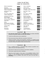
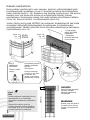
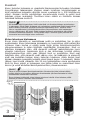
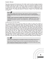
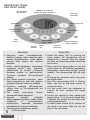
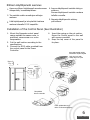
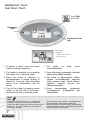
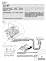
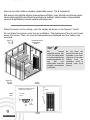
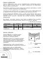
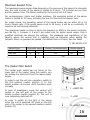
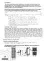
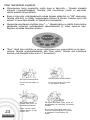
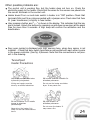
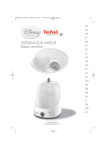
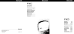
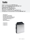
*to be purchased separately
with USERPANEL:
-Classic
- Touch
Classic
Touch
SÄHKÖKIUAS
ELECTRIC SAUNA HEATER
Ei käytössä seuraavissa maissa: USA, Kanada ja Meksiko.
Not for use in the USA, Canada and Mexico.
TAKUUAIKA
Takuuaika perhe-/ kotisaunoissa on yksi (1) vuosi alkaen kiukaan
toimituspäivästä. Asunto-osakeyhtiöissä takuuaika on kuusi (6) kuukautta.
Kylpyläsaunoissa ja muissa julkisissa saunoissa takuuaika määräytyy
käyttöasteen mukaan. Lisätietoja maahantuojalta.
LAATUTAKUU
Takuuaikana ilmenneet raaka-aineesta tai valmistusvirheistä johtuvat viat
korjataan veloituksetta. (Esim. suolaveden käyttö kiukaan löylyvetenä on
kielletty.) Takuu ei kata luonnonkivelle ominaista värivaihteluita, lustoisuutta ja
hiushalkeamia, jotka eivät vaikuta turvallisuuteen ja toimintaan. Takuu ei
myöskään kata käyttövirheistä kuten väärien kiuaskivien tai meriveden
käytöstä johtuvia vikoja.
Kuljetusvahingoista on tehtävä merkintä rahtikirjaan tavaraa vastaanotettaessa
tai seitsemän päivän kuluessa tavaran saapumisesta vastaanottajalle.
Kuljetusvahingoista on myös ehdottomasti ilmoitettava kuljetusliikkeen
viimeiselle toimipisteelle. Vahingoittunut osa on säilytettävä tarkastusta varten.
Vakuutus korvaa vahingoittuneen osan tilalle uuden. Osa toimitetaan yleisiä
kuljetusvälineitä kuten Matkahuoltoa käyttäen. Takuuasiat on hoidettava
aina liikkeen kautta josta tuote on ostettu.
WARRANTY TIME
Warranty time of household sauna is one (1) year starting from the day of
delivery. In condominium sauna warranty time is six (6) months. Warranty time
of sauna in public baths and in other public places is calculated from hours of
usage. More information about public sauna warranty from heater importer.
QUALITY WARRANTY
Defects in sauna heater caused by raw materials or by manufacturing mistakes
are fully compensated during warranty time. Warranty doesn’t cover variation
of color, normal breaking lines or hairline cracks in stones that doesn’t affect
functionality or safety. Warranty doesn’t cover damages caused by improper
stones or salty/chlorinated water.
Transportation damages must be noticed when receiving goods, latest within 7
days from receiving. Transportation damages must be informed also to
forwarding company. Store damaged parts for later evaluation. Insurance will
replace damaged goods by new ones. Warranty claims must be always
dealt with the shop that sold the heater.
SISÄLLYSLUETTELO
TABLE OF CONTENTS
Kiukaan asentaminen
Kiuaskivet
Käyttöpaneli: Classic
Erillisen käyttöpanelin asennus
Käyttöpaneli: Touch
Tunnistin
Ovitunnistin (lisävaruste)
Tuuletin (lisävaruste)
Himmennin (lisävaruste)
Kytkentäkaavio
Maksimi päälläoloajat
Ohjauskeskuksen pääkytkin
Ilmanvaihto
Eristys
Saunahuoneen lämmitys
Kiukaan Puinen Suojakaide
Tekniset tiedot
Varaosat
Vianetsintä
Turvaohjeet
1
Heater Installation
2
3
5
6
7
8
10
10
10
11
15
15
17
18
18
19
20
20
21
25
Heater Stones
User Panel: Classic
Installation of the Control Panel
User Panel: Touch
Sensor
Door Sensor (optional)
Fan (optional)
Dimmer (optional)
Electrical Diagrams
Maximum Session Time
Control Unit Main Switch
Air Ventilation
Insulation
Heating Of The Sauna
Wooden Heater Guard Rail
Technical Data
Spareparts
Troubleshooting
Heater Precautions
4
5
6
7
8
10
10
10
11
16
16
17
19
19
19
20
20
22
25
Varoitukset
1. Vain valtuutettu sähköasentaja voi tehdä asennustyön ja suorittaa mahdolliset
huoltotyöt ja korjaukset. Käytä vain alkuperäisiä varaosia.
2. Irroita kiuas sähköverkosta ennen asentamista.
3. Ennen asennusta tarkista sähköverkon jännitteen soveltuvuus.
4. Tarkasta tunnistimien sijainti asennusohjeiden mukaisesti. On tärkeää asentaa
tunnistimet oikein, liian lähellä tunnistimia olevat ilmanvaihtoventtiilit viilentävät
tunnistimia liikaa ja aiheuttavat kiukaan ylikuumenemisen.
Precautions
1. Only a qualified electrician is allowed to make electrical connections and
repairs on the unit. Use original parts only.
2. Disconnect the heater from the electrical circuit before installation.
3. Check power supply rating before installation.
4. Check the correct location of the sensor in the installation section of the
manual. It is very important to place the temperature sensor correctly as it
closeness to the air ventilation cools down the sensor and may lead to
overheating.
Kiukaan asentaminen
Kiuas voidaan sijoittaa mihin vain saunaan, kuitenkin vähimmäisetäisyyksiä
turvallisuussyistä noudattaen (kuva 2). Noudata annettuja kuutiotilavuuksia
(katso tekniset tiedot s. 19). Kiuasta ei saa asentaa syvennykseen. Älä asenna
saunaan kuin yksi kiuas ellei sinulla ole erikoisohjeita kahden kiukaan
asentamiseen. Useimmissa maissa, laki vaatii kiukaan kiinnittämisen lattiaan
(kuva 1a). Asenna tukitikut turvallisuussyistä (kuva 1b).
Johdon täytyy olla tyyppiä HO7RN-F tai vastaavaa. Kiuaskytkennät saa tehdä
ainoastaan valtuutettu sähköasentaja, turvallisuuden ja luotettavuuden
varmistamiseksi. Väärät kytkennät voivat aiheuttaa oikosulkuja ja palovaaran
(kytkentäkaavio sivu 11).
* Löylynohjain
2
Kierrä
säätääksesi
korkeuden.
Kuva. 1b
Fig. 1b
Ruuvattava suoraan
lattiaan estämään
kiukaan
liikkuminen.
Must be screwed
directly on the floor
to prevent the
heater from being
accidentally moved.
100mm
Twist to adjust
height.
JALKA
STAND
Huom!
Poista suojapahvi vastuksista ennen
asentamista, se on tarkoitettu
ainoastaan suojaamaan kuljetuksen
ajaksi.
Remove the carton from the
heating elements before installing
the heater as it is only intended to
protect them during shipment.
1
SOUMI / ENGLISH
1300mm
Note
200mm
Kuva. 1a
Fig. 1a
täytyy kiinnittää
kiukaaseen.
* Refelector
must be attached
to the heater
HUOMIO
Kiinnitä kiuas tarpeeksi
vahvaan seinään.
Vahvista panelointia
tarvittaessa.
WARNING
Heater must be fixed to
the wall that is strong
enough to support the
heater.
Heater Installation
The heater can be placed next to the sauna wall, but for safety and
convenience, follow the minimum safety distances as provided in Fig. 2. Follow
the cubic volumes given in the Technical Data (page 19). Do not install the
heater to the floor or wall niche. Do not install more than one heater in a sauna
room unless you follow the special instructions for twin-heater installations. In
most countries, there is a law that requires heaters to be screwed to the floor
as provided in Fig. 1a. Fix the heater to a wall like shown in Fig. 1b.
The heater gets very hot. To avoid the risk of accidental contact with the heater,
it is recommended that a heater guard be provided. See Fig. 10 on Page 19
The cable used for sauna wiring must be HO7RN-F type or its equivalent. A
certified electrician must do the installation of the heater to ensure safety and
reliability. Improper electrical connection can cause electric shock or fire. Refer
to the electrical diagram in page 11.
Kuva 2
Fig. 2
Vähimmäisturvaetäisyydet (mm)
Minimum Safety Distances (mm)
HUOM:
Tarkista ohjauskeskuksen tehonkesto
ohjauskeskuksen käyttöohjeesta.
Kontaktoriyksikkö tarvitaan, jos
kiukaan teho ylittää erillisen ohjauskeskuksen kapasiteetin.Erillinen kontaktoriyksikkö voidaan liittää kiukaisiin joiden teho on 10,5kW tai
enemmän.
100
100
A
Kajo 8 kW i TH6-80Ni-WL 1900
Kajo 9 kW i TH6-90Ni-WL 1900
20
max. 500
A
NOTE:
Please refer to the control unit
manual for maximum power rating.
Contactor unit is needed if heater’s
power rating exceeds separate
control unit’s capacity. Additional
contactor unit can be connected to
the heaters 10,5kW and higher.
A
Kajo 15 kW i TH12-150Ni-WL 2300
Kajo 10,5kW i TH6-105Ni-WL 1900
Kajo 180 kW i TH12-180Ni-WL 2300
Kajo 21 kW i TH12-210Ni-WL 2300
Kajo 12kW i TH6-120Ni-WL 2100
Kajo 24 kW i TH12-240Ni-WL 2300
Kajo 10,5 kW i TH9-105Ni-WL 1900
Kajo 12 kW i
TH9-120Ni-WL 2100
Kajo 15 kW i
TH9-150Ni-WL 2100
2
SOUMI / ENGLISH
Kiuaskivet
Kivien tarkoitus kiukaassa on varastoida lämpöenergiaa löylyveden tehokkaan
höyrystämisen takaamiseksi. Kiukaan oikean toiminnan varmistamiseksi on
kivet poistettava kiukaasta vähintäin kerran vuodessa tai n. 500 käyttötunnin
välein. Kiukaan kivitila puhdistetaan murentuneista kivistä ja uudet kivet
ladotaan ohjeen mukaisesti. Tarvittava kivien määrä on ilmoitettu kiukaan
teknisissä tiedoissa sivulla 21.
Huom!
Älä koskaan
an käy
käytä kiuasta ilman kiviä koska tämä voi aiheuttaa kiukaan vaurioitumisen
ja palovaaran. Käytä SaWo-kiukaassa vain valmistajan suosittelemia SaWo-kiuaskiviä tai
muita raskaita ja kiinteitä erityisesti kiuaskiviksi tarkoitettuja kiviä. Riittävän ilman
kierron varmistamiseksi ja lämmityselementtien ylikuumenemisen sekä mekaanisen
vaurion välttämiseksi, älä käytä SaWo-kiukaissa teollisesti valmistettuja säännöllisen
muotoisia keraamisia kiuaskiviä. Älä myöskään käytä huokoisia ja/tai pehmeitä tai
murenevia luonnonkivilajeja kuten vuolukiveä.
Kivien latominen kiukaaseen
Ennen kivien latomista on suositeltavaa pestä ne mahdollisen lian ja pölyn
poistamiseksi. Kivien latomisessa kiukaaseen on huomioitava, että kiukaan läpi
virtaavan ilman kiertoa ei estetä koska tämä johtaa lämmityselementtien
ylikuumenemiseen ja niiden käyttöiän merkittävään lyhenemiseen. Kivet on
ladottava kiukaaseen siten, että elementit peittyvät mahdollisimman hyvin
ulkopäin katsottuna. Isokokoisia kiviä ei saa milloinkaan työntää väkisin
lämmityselementtien väliin vaan tällaiset kivet on poistettava. Kivet ovat
ladottava siten, että elementit eivät väänny ulos- tai sisäänpäin ja elementit
eivät saa koskettaa toisiaan kivien ladonnan tuloksena. Aseta ensiksi kivet
kiukaan alaosaan avaamalla keskellä olevat kaaret kuvan 3 mukaisesti, tämän
jälkeen loput kivistä yläkautta. Alle 35 mm halkaisijaltaan olevia pienikokoisia
kiviä tai kiven paloja ei kiukaaseen saa laittaa koska ne vaarantavat ilman
kierron ja voivat aiheuttaa lämmityselementtien ylikuumenemisen.
Huom!
Takuu ei korvaa kiukaan lämmityselementtien rikkoutumisia jotka johtuvat väärän
kivilajin käytön tai virheellisen ladonnan aiheuttamasta ylikuumenemisesta tai niiden
aiheuttamista mekaanisista vaurioista.
Ennen kiukaan kivittämistä, tulee kiukaan toimivuus kokeilla. Kiuas laitetaan päälle
hetkeksi ja kaikkien vastusten tulee lämmetä.
Kuva 3
Fig. 3
1
3
SOUMI / ENGLISH
Heater Stones
The main purpose of the stones in the heater unit is to store enough energy to
efficiently vaporize the water thrown on top of the stones to maintain correct
humidity in the sauna room. The stones must be removed at least once a year
or every 500 hours which ever occurs first. All stone crumbles must be
removed from the heater unit and replaced with new ones as described in the
heater manual. The required amount of stones is listed in the Technical Data
on page 21.
Note
Never use the heater without stones as it may cause fire. Use only manufacturer
recommended SaWo-stones. Using unsuitable stones may lead to heating element
damage and will void the warranty. Never use eramic stones or other artificial stones of
any type!
If heater is used in commercial or public place, Kajosauna Oy recommends to use
KERKES ceramic heater stones. KERKES ceramic stones are designed for sauna heaters
and KERKES stones don’t crumble in high temperatures. NOTE: soap stone or other
natural stones should be used only in the surface of the heater. Not touching heating
elements.
Loading stones into the heater
It is recommended that all stones should be rinsed to remove any stains or
dust that can cause unpleasant odour during the first few times of using the
heater. It is important that the stones are loaded carefully in a way that they
do not block air circulation through the heater. Load the stones to the heater so
that the heating elements are not visible from any angle. First place stones to
the lower part of the heater. In order to make space for loading the stones, fold
arcs to open as shown in Fig.3. Put the arcs back properly and load the rest of
the stones from the top. Make sure that the elements don’t get bended or
touch each other as a result of the loading. Larger stones that won’t fit
between the heating elements must not be forced in place instead they must
be completely removed. Small crumble or stone pieces smaller than 35mm in
diameter must not be loaded into the heater because they will block the air
circulation and will cause overheating and possible heating element damage.
Note
Heating element damage due to overheating caused by wrong kind of stones or stones
which were wrongly loaded into the heater is not covered by the factory warranty.
Before the tower heater is filled with stones, electrician should test that the heater
works. Testing can be done by turning on the heater for a short time without any stones
and verifying that all heating elements are heating up.
4
SOUMI / ENGLISH
Käyttöpaneli: Classic
User Panel: Classic
LED merkkivalot
LED indicators
Näppäimet ja merkkivalot
Buttons and States (Illustration)
LED näyttö
LED display
Saunahuoneen valo
Light
Virtanäppäin
Power
Esiajastus näppäin
Pre-run Timer
Toimintonäppäin
Mode
Ajastin
Timer
Alas
Down
Kiuas
Heater
Höyrystin
Steamer
Valitse-näppäin
Toggle / Select
Tuuletin
Fan
Pikaohjeet
kiuas
virtanäppäimestä.
1. Käynnistä
Näyttöön ilmestyy viiden sekunnin ajaksi
saunan tavoitelämpötila, jonka jälkeen
näkyviin tulee saunan sen hetkinen
lämpötila.
2. Lyhyet Valitse-näppäimen painallukset
muuttavat näytön tilaa: lämpötila,
päälläoloaika ja tuuletin (toiminnot
saattavat poiketa eri malliversioilla).
Toimintoa vastaavat LED-merkkivalot
palavat.
3. Kun haluat muuttaa toimintoja paina
Valitse-näppäintä ja pidä sitä hetkisen
pohjassa haluamasi toiminnon kohdalla.
vastaava
LED-merkkivalo
4. Toimintoa
vilkkuu, Alas- ja Ylös-näppäimillä voit
säätää arvoa.
siirtyä
toiminnosta
toiseen
5. Voit
painelemalla Valitse-näppäintä.
valintasi
pitämällä
6. Vahvista
Valitse-näppäintä pohjassa. Vaikka Valitse
näppäintä
ei
painettaisikaan,
ohjauskeskus
vahvistaa
muutokset
automaattisesti 5 sekunnin kuluttua.
7. Yleensä saunan lämpiäminen kestää
35-50 minuuttia.
5
SOUMI / ENGLISH
Ylös
Up
Suhteellinen kosteus
Relative Humidity
Lämpötila
Temperature
Quick Start
1. Switch the heater "ON" by pressing the
power button. Set temperature will be
displayed for 5 seconds. After this display
will show the actual temperature inside the
sauna room.
2. Short press the toggle button to see the
actual values for the different parameters:
temperature, session time and fan* (not all
models). The corresponding LED will light
up.
3. To change the parameter value, long press
the toggle button.
4. Now the corresponding LED is blinking
faster. Use the up and down arrows to
change the value.
5. You can move from one parameter to
another by short pressing the toggle
button.
6. Confirm the settings by long pressing the
toggle button. If no keys are pressed after
5 seconds, the control unit will confirm the
changes automatically.
7. It usually takes around 35-50 minutes for
the sauna to get warm. After this you can
start to use your sauna.
Erillisen käyttöpanelin asennus
1. Asenna erillinen käyttöpaneli saunahuoneen
ulkopuolelle, huonelämpötilaan.
2. Tee seinään aukko annettujen mittojen
mukaan.
3. Liitä käyttöpaneli ja tehoyksikkö toisiinsa
mukana tulevalla RJ 12 kaapelilla.
4. Asenna käyttöpaneli seinään tehtyyn
aukkoon.
Ruuvaa käyttöpaneli seinään mukana
tulleilla ruuveilla.
5. Napauta käyttöpanelin etulevy
pai-koilleen.
Installation of the Control Panel (See IIlustration)
1. Mount the Separate control panel
casing outside the sauna room, in
preferred, secure area on a room
temperature.
2. Cut the wall section according to the
specifications.
3. Connect the RJ12 cable provided from
the control panel to the Power
Controller.
4. Insert the casing on the cut section.
Screw the Control panel to the wall
with screws provided.
5. Snap the top cover of the panel to
its place.
Avaa painamalla reikää
esimerkiksi kynän kärjella
Push the hole with
sharp object to open
2.
25mm
161mm
85mm
Kuva 4
Fig. 4
5.
4.
Tehoyksikkö
Power Controller
Katso johdotuskuva 11.
Refer to Electrical Diagram
6
SOUMI / ENGLISH
Käyttöpaneli: Touch
User Panel: Touch
Kiuas Päälle
Heater ON
Virtanäppäin
Power
Saunahuoneen Valo
Light
Kiuas päälla
Heater ON
* Tuuletin on lisöva ruste
* Fan is optional
1. If display is blank press the power
button to activate userpanel.
1. Jos
näyttö
on
virtananäppäintä.
tyhjä,
paina
2. The heater is switched on by pressing
the heater icon in stand-by mode.
2. Kiuas käynnistyy painamalla näytössä
olevaa kiuas päälle symbolia.
3. When the heater is switched on
set-temperature is shown blinking in
display for 5 seconds. After this actual
sauna room temperature will be
shown.
3. Kun kiuas on käynnistetty, vilkkuu
saunan tavoitelämpötila näytössä
viiden sekunnin ajan. Tämän jälkeen
näyttöön ilmestyy saunan sen
hetkinen lämpötila.
4. Turn off the heater by pressing power
button on the left side of the screen.
Userpanel will stay in stand-by mode.
4. Kiuas
sammutetaan
painamalla
virtanäppäintä. Ohjauspaneli jää
valmiustilaan.
Huom!
Note
Always check that there are no combustible
materials, like towels, above the heater, nor
inside the safety distances, before switching the
heater on! The safety distances are stated in
the heater manual.
7
SOUMI / ENGLISH
Tarkista aina ennen kiukaan tai esiajastuksen
käynnistämistä, ettei kiukaan päällä tai
läheisyydessä ole mitään palavia materiaaleja
kuten pyyhkeitä. Huomio turvaetäisyydet, jotka
löytyvät kiukaan ohjekirjasta.
Tunnistin
Sensor
Huom!
Note:
Varmista, että asennat lämpötilatunnistimen
ylikuumenemissuojalla
kiukaan
yläpuolelle
myöhemmin annettavien ohjeiden mukaisesti.
Katso kuva 7 ja 8.
Make sure you mount the temperature sensor
with the fuse, above the heater following the
instructions given in the Sensor section! See
figure 7 and 8.
Lämpötilatunnistimen johto koostuu kahdesta
erilaisesta johdosta. Asenna silikonieristeisen
johdon pää lämpötilatunnistimeen. Älä pinta-asenna
PVC kaapelia löylyhuoneen sisään. Pintaasennukseen soveltuva silikonikaapeli on saatavana
erikseen.
Wire of temperature sensor consist of two
different cables. Install the silicone cable part to
temperature sensor. Do not mount the PVC cable
inside the sauna room. For that purpose, silicon
cable is available upon request.
Turvallisuussyistä noudata asennusohjeita tarkasti!
For safety reasons, please follow the instructions!
Kuva 5
Fig. 5
T/H SENSOR 3
T/H SENSOR 1
DOOR SWITCH
TS2
TS1
TEMP.FUSE
T/H SENSOR 4
T/H SENSOR 2
DOOR SWITCH
TS2
TS1
TEMP.FUSE
4
Valkoinen WHITE
1
Sininen BLUE
3
Musta BLACK
Ruskea BROWN
2
Kuva 6
Fig. 6
Lämpötilatunnistin
ylikuumenemissuojalla
TEMP. SENSOR & FUSE
R1
F1
1
TS
TS1
4
2
3
FUS
TEMPFUSE
Maksimi päälläoloajan valinta
Jumper for maximum session time
6Tuntia 18Tuntia
hrs
hrs
JPB1
Siirtämällä liitintä saat muutettua päälläoloja esiajastusaikaa.
1
4Tuntia 12Tuntia 24Tuntia
hrs
hrs
hrs
By changing the place of jumpers, you can
adjust the session time and pre-run time
8
SOUMI / ENGLISH
Asenna tunnistin kattoon kiukaan yläpuolelle kuvien 7 ja 8 mukaisesti.
Älä asenna tunnistinta lähelle ilmanvaihtoventtiilejä. Liian lähellä tunnistimia olevat
ilmanvaihtoventtiilit viilentävät tunnistimia ja antavat väärän tiedon tehoyksikölle
saunan lämpötilasta ja kiuas saattaa ylikuumentua.
Place the sensor to the ceiling, over the heater, as shown in the figures 7 and 8.
Do not place the sensors near the air ventilation. The closeness of the air vent cools
down the sensor. Thus, an incorrect temperature is displayed and the heater may
overheat.
Kuva 7
Fig. 7
Lämpötilatunnistin
Temperature
Sensor
Huom!
Note
Älä
asenna
lämpötila-anturia alle
1000 mm etäisyydelle
suuntaa-mattomasta
tuloilmaventtiilistä tai
alle
500
mm
etäisyydelle anturista
poispäin suunnatusta
venttiilistä.
Kuva 8
Fig. 8
KATTO
CEILING
Mahdolliset tunistimen sijainnit
Possible sensor locations
SEINÄ
WALL
100mm
Tunnistin
Sensor
100mm
9
SOUMI / ENGLISH
LATTIA
FLOOR
Do not place the
sensors too near to air
ventilation (not under
1000mm) or not under
500mm
from
air
ventilation, which is
directed away from
sensors.
Ovitunnistin (lisävaruste)
Muussa kuin kotikäytössä on suositeltavaa asentaa ovitunnistin. Ovitunnistin kytkee
pois päältä kaikki aktiiviset esiajastustoiminnot mikäli ovi on auki.
Ovitunnistin myös varmistaa, että saunan ovi ei ole liian pitkään avoinna, kun kiuas
on päällä. Jos kiuas on päällä ja ovi on auki yli 15 minuuttia, varoitusääni ja
”DOOR”-teksti näytössä ilmoittavat asiasta. Kiuas sammuu automaattisesti.
Huom!
Mikäli ovitunnistinta ei ole asennettu, tulee ohjauskeskuksen riviliittimet "Door switch" (kt. kuva 5 /
Tunnistimet) kytkeä toisiinsa yhdyslangalla
Tuuletin (lisävaruste)
Tuuletinta voi käyttää vain jos toiminto on olemassa ohjauskeskuksessa.
Saunahuoneen tuulettimessa pitää olla joko sulkunapa- tai oikosulkumoottori, jotta
ohjauskeskus voi ohjata sen tehoa. Max teho 100W 230V jännitteessä.
Valaistuksen himmennin (lisävaruste)
Mikäli himmennintoiminto on kytkettynä ohjauskeskukseen voit säätää saunahuoneen valaistuksen voimakkuutta. Vain hehkulamput ovat säädettävissä.
Door Sensor (optional)
In other than household use, it is recommended to install door sensor. The door
sensor disables all pre-run operations if the door is opened while the pre-run
countdown is active.
The door sensor also ensures that the door is not open for long periods of time
when the heater is on. If the heater is on and the door is open for more than
15minutes, an alarm and “DOOR” will be displayed to warn the user. The heater will
be switched off automatically.
Note:
If no door sensor is installed, "Door switch" terminals in the Power Controller must be connected with
each other by a jumper wire. See Fig. 5. Note: connection is not present in the drawing.
Fan (optional)
The fan function can only be activated if the fan feature is present on the control
unit. Ensure that the fan motor to be controlled is either shaded pole or permanent
split capacitor motor. The maximum power is100W with 230 VAC.
Dimmer (optional)
It is possible to use any suitable lamp of your choice in the sauna room. However, if
the dimmer feature is present on the control unit and wished to be used, only
incandescent lamp is suitable.
10
SOUMI / ENGLISH
11
SOUMI / ENGLISH
2.0
1.5
2.0 2.0
2.0
1.5 2.0 1.5
1.5 1.5
2.0
KAJO-12kW i
2.0
1.5
TH6-120Ni-WL 12.0 2.0
H6
1.5
H5
1.5
H4
1.5
H3
KAJO-10,5kW i TH6-105Ni-WL 10.5 2.0
H2
1.5 1.15 1.5 1.15 1.5 1.15
H1
9.0
TH6-90Ni-WL
kW
1 2 3 4 5 6
HH H H HH
PE
N
3
W TB N2 STBY DRAINFILLFAN
N
V U LIGHT STBY N N N
8.0
TH6-80Ni-WL
KAJO-9kW i
Model
KAJO-8kW i
Heater
(R) L1
(S) L2
(T) L3
N
PE
5
R S T N N N N N UB U V W
Max. 15.0 kW
400V 3N~
50-60HZ
3
T
4 2
TS1
DOOR
TS2
T/H
Temp.Fuse TS1
T
Temp
Fuse
T
TS2
4
SENSOR
2 1 1 D 1 3
3 4 4 D 2 4
CONTROLLER
T
RH
User Interface
Board
Contactor Unit
T / H Sensor
Control
Kytkentäkaavio
Electrical Diagram
TB: Control of Heating
NON-FUSED
Heater
5
Model
kW
H1
H2
H3
H H H H H H H H H
1 2 3 4 5 6 7 8 9
R S T N N N N N UB U V W
H4
PE
H5
H6
H7
3
H8
N DRAIN FILL FAN
W TB N2 STBY
N
LIGHT
V U
STBY N N N
NON-FUSED
H9
3
T
T
Temp.Fuse
Temp
Fuse
TS1
4 2
TS1 DOOR
TS2
T/H
T
4
TS2
SENSOR
2 1 1 D 1 3
3 4 4 D 2 4
CONTROLLER
KAJO-9kW i TH9-105Ni-WL 10.5 1.15 1.15 1.15 1.15 1.15 1.15 1.15 1.15 1.15
KAJO-12kW i TH9-120Ni-WL 12.0 1.5 1.15 1.5 1.5 1.15 1.5 1.5 1.15 1.15
KAJO-15kW i TH9-150Ni-WL 15.0 2.0 1.5 1.5 2.0 1.5 1.5 2.0 1.5 1.5
(R) L1
(S) L2
(T) L3
N
PE
Max. 15.0 kW
400V 3N~
50-60HZ
TB: Control of Heating
12
SOUMI / ENGLISH
T
Control
T / H Sensor
RH
User Interface
Board
Contactor Unit
Max. 15.0kW
400V 3N~
50-60HZ
5
Heater
PE
V U
N
3
N
FAN
3
T
Temp.Fuse TS1
T
4
1
2
Model
3
4
5
kW
6
H1
DOOR
2 1 1 D 1 3
3 4 4 D 2 4
Temp
Fuse
H H H H H H
LIGHT STBY
N
W TBN2STBY
CONTROLLER
POWER CONTROLLER
H2
User Interface
Board
(R) L1
(S) L2
(T) L3
N
PE
7
H3
8
H4
9
H5
H6
H7
10 11 12
H8
5
H9
H10
H11
R S T N N N N N UB U V W
H H H H H H
Control
Temp
Fuse
1 1
2 2
Please make sure that the
jumper is connected to temp
fuse terminals.
Varmista, että jumpperi on
asennetu
“Temp
Fuse”
terminaaleihin.
Huom!
Note
H12
PE
N
N2 STBY
N
LIGHT STBY
CONTROLLER
CONTACTOR UNIT
KAJO-18kW i TH12-180Ni-WL 18.0 1.5 1.5 1.5 1.5 1.5 1.5 1.5 1.5 1.5 1.5 1.5 1.5
KAJO-21kW i TH12-210Ni-WL 21.0 1.5 1.5 1.5 1.5 1.5 1.5 2.0 2.0 2.0 2.0 2.0 2.0
KAJO-24kW i TH12-240Ni-WL 24.0 2.0 2.0 2.0 2.0 2.0 2.0 2.0 2.0 2.0 2.0 2.0 2.0
R S T N N N N N UB U V W
13
(R) L1
(S) L2
(T) L3
N
PE
SOUMI / ENGLISH
Heater
Model
kW
H1
H2
H3
H4
H5
H H H H H H H H H H H H
1 2 3 4 5 6 7 8 9 10 11 12
H6
PE
H7
H8
3
N DRAIN FILL FAN
W TB N2 STBY
N
LIGHT
V U
STBY N N N
NON-FUSED
H9
3
H10
H11
Temp
Fuse
H12
T
4 2
T
Temp.Fuse
TS1 DOOR
TS2
T/H
4
TS1
SENSOR
2 1 1 D 1 3
3 4 4 D 2 4
CONTROLLER
KAJO-15kW i TH12-150Ni-WL 15.0 1.15 1.15 1.15 1.5 1.15 1.15 1.15 1.5 1.15 1.15 1.15 1.5
(R) L1
(S) L2
(T) L3
N
PE
5
R S T N N N N N UB U V W W
Max. 15.0 kW
400V 3N~
50-60HZ
TB: Control of Heating
SOUMI / ENGLISH
14
T
TS2
Control
T
T / H Sensor
RH
User Interface
Board
Contactor Unit
Maksimi päälläoloajat
Maksimi päälläoloaika riippuu saunan käyttökohteesta. Kotikäytössä maksimiaika on rajattu kuuteen tuntiin. Se sisältää esiajastuksen ja päälläoloajan.
Tehdas- asetus on kuusi tuntia.
Taloyhtiöissä, hotelleissa ja muissa vastaa vissa kohteissa maksimiaika on rajattu
12 tuntiin, sisältäen esiajastuksen ja päälläoloajan.
Yleisissä saunoissa päälläoloaika voi olla joko 18 tai 24 tuntia. Mikäli päälläoloaika
on ajastettu 24 tuntiin, sauna on aina päällä ja vaatii jatkuvaa valvontaa.
Maksimi päälläoloajat säädetään piirilevy- kortilla olevilla liittimillä, katso kuva 5.
Suomessa liittimet 3, 4 ja 5 ovat tarkoitettu ainoastaan yleisiin, kaupallisessa
käytössä oleviin saunoihin. Asetuksia saa muuttaa ainoastaan valtuutettu
sähköasentaja.
Kun liittimiä asennetaan, kyseisen maan lakeja ja säädöksiä tulee noudattaa.
Mikäli liittimiä ei ole asennettu lainkaan, asetus on 6 tuntia. Ks. Taulukko.
*) IEC 60335-2-53 mukaan
Sauna Tyyppi
Liittimet
Kotisauna
1
2
Maksimi päälläoloaika
4 tuntia
6 tuntia
Maksimi
esiajastusaika
3 tuntia
5 tuntia
Hotellit, kerrostalot
Yleinen sauna
3
12 tuntia
4
5
18 tuntia
24 tuntia
99 tuntia
Kiukaan pääkytkin
Kiukaan pääkytkin on sijoitettu kiukaan
alaosaan. Pääkytkin irroittaa kiukaan
elektroniikan verkkojännitteestä.
Pääkytkimen asento I on tarkoittu normaalia
toimintaa varten. Ainostaan tässä kytkimen
asennossa ohjauskeskus voi ohjata kiuasta ja
ohjauskeskuksen muut toiminnot toimivat
normaalisti.
Ohjauskeskuksen irroitus verkosta tapahtuu
kääntämällä pääkytkin keskiasentoon (asento 0).
Saunahuoneen valon voi laittaa päälle
kääntämällä pääkytkin asentoon II. Tällöin
ohjauskeskuksen elektoniikka säilyy verkosta
irroitettuna.
II 0
I
I = Ohjauskeskus
päällä
0 = Pois päältä
II = Valot päällä
15
SOUMI / ENGLISH
Maximum Session Time
The maximum sauna session time depends on the purpose of the sauna. For domestic
use, the total on-time of the sauna is limited to 6 hours. *)It includes pre-run time
and the session time. The factory setting for the control unit is 6 hours.
For condominiums, hotels and similar locations, the operating period of the sauna
heater is limited to 12 hours, including the pre-run time and the session time.
For public sauna, the operating period of the sauna heater can be either 18 or 24
hours. Please note, if the public sauna is set to 24 hours, it will be on constantly. It
needs to be continuously attended.
The maximum heater on-time is set by the jumpers on SCB1 in the power controller,
see the Fig. 5. Jumpers 3, 4 and 5 are meant only for public sauna rooms. Only a
qualified electrical can change the settings. The standards and regulations of the
country where the control unit is installed must be followed, when setting the
jumpers. When no jumpers are placed, the default time is 6 hours. See the Table.
*) IEC 60335-2-53
Sauna Type
Jumper
Domestic sauna
Hotels, Condominiums
Public sauna
1
2
3
4
5
Max. time
4h
6h
12h
18h
24h
Max. pre-run time
3h
5h
99h
The Heater Main Switch
The heater main switch can be found on the
lower part of the heater. Using this switch, you
can isolate the electronics from the mains power
supply.
In order to put the unit into operation, switch to
the first position (switch position I). In this
switch position all control unit’s functions work
normally.
In case of breakdown, press the control unit
switch on the left part of the rocker to the
middle position (switch position 0). The unit is
now completely switched off.
In order to switch on the light in the sauna
when the unit is switched off, press on the left
part of the rocker to the second position (switch
position II).
II 0
I
I = UNIT ON
0 = OFF
II = LIGHT ON
16
SOUMI / ENGLISH
Ilmanvaihto
Saadaksesi miellyttävän ilmatilan saunaan siellä pitäisi olla kuumaa ja raikasta
ilmaa sopivassa suhteessa. Ilmanvaihdon tarkoitus on kierrättää kiukaan
ympärillä oleva ilma saunan kaukaisimpaankin nurkkaan. Tulo- ja
poistoilmaventtiilien sijainnit vaihtelevat saunan mallista sekä omistajan
mieltymyksistä riippuen.
Tuloilmaventtiili voidaan asentaa seinälle suoraan kiukaan alle (kuva 9A).
Koneellista ilmastointia käytettäessä tuloilmaventtiili voidaan asentaa
vähintään 60 cm:n korkeuteen kiukaan yläpuolelle (kuva 9B) tai kattoon
kiukaan yläpuolelle (kuva 9C). Näin asennettuna, ulkoa tuleva raskas kylmä
ilma sekoittuu kevyeen kuumaan kiukaasta tulevaan ilmaan, tuoden raikasta
ilmaa saunojille. Suositeltava tuloilmaventtiilien koko on 5-10 cm.
Poistoilmaventtiili pitäisi sijoittaa diagonaalisesti tuloilmaventtiiliä vastapäätä,
mieluiten lauteiden alle mahdollisimman kauas raitisilma-aukosta. Se voidaan
asentaa lähelle lattiaa, johtaa putkea pitkin katolla sijaitsevaan
poistoilmaventtiiliin tai johtaa oven alitse kylpyhuoneessa olevaan
poistoventtiiliin. Tällöin saunan kynnysraon on oltava vähintään 5 cm ja
kylpyhuoneessa olisi suotavaa olla koneellinen ilmastointi. Poistoilmaventtiilin
pitää olla kaksi kertaa suurempi kuin tuloilmaventtiilin.
Kuva 9
Fig. 9
A
B
C
Air Ventilation
To have a soothing sauna, there should be a proper mixing of hot and cold air
inside the sauna room. Another reason for ventilation is to draw air around the
heater and move the heat to the farthest part of the sauna. The positioning of the
inlet and outlet vents may vary depending on the design of the sauna room or
preference of the owner. Nordic spruce wood is recommended for the walls and
ceiling inside the sauna.
The inlet vent may be installed on the wall directly below the heater (Fig. 9a).
When using the mechanical ventilation, the inlet vent may be placed at least 60
cm above the heater (Fig. 9b) or on the ceiling above the heater (Fig. 9c).
Through these positions, the heavy cold air that is blown into the sauna is mixed
with the light hot air from the heater, bringing fresh air for the bathers to breathe.
The recommended size for the inlet vent is 5-10 cm.
The outlet vent should be placed diagonally opposite to the inlet. It is
recommended that the outlet vent be placed under the platform in a sauna as far
as possible from the fresh air vent. It may be installed near the floor, or led
outside through a pipe from the floor going to a vent to the sauna ceiling, or
under the door (to the washroom). In this case, the sill slot must be at least 5 cm
and it is recommended that there is mechanical ventilation in the
washroom. The size of the exhaust should be twice that of the inlet.
17
SOUMI / ENGLISH
Eristys
Saunassa pitää olla asianmukaiset eristykset seinissä, katossa ja ovessa.
Oikean tehoista kiuasta valittaessa on huomioitava: Jos saunassa on yksi
neliömetri (m²) eristämätöntä seinäpintaa (esim. lasiovi, tiili- tai
kaakeliseinä), on saunan tilavuuteen laskettava lisää suunnilleen 1,2
kuutiometriä (m³) (tekniset tiedot sivu 20.).
Kosteuseristyksen pitää olla saunassa hyvä, koska sen tarkoitus on estää
saunan kosteuden leviäminen muihin huoneisiin ja seinärakenteisiin.
Kosteuseristys täytyy sijoittaa lämpöeristyksen ja paneelien väliin. Saunan
seinät ja katto on suositeltavaa paneloida kuusella.
Lämpö- ja kosteuseristys asennetaan seuraavan järjestyksen mukaisesti
ulkoa sisälle:
1. Lämpöeristyksen suositeltava minimipaksuus seinissä on 50 mm
ja katossa 100 mm.
2. Höyrysulkuna voi käyttää pahvi- tai alumiinifoliolaminaattia,
joka kiinnitetään eristyksen päälle alumiinifolio sisäänpäin.
3. Jätä vähintään 20 mm ilmarako höyrysulun ja sisäpaneelin
väliin.
4. Estääksesi kosteuden kerääntymisen paneelin taakse jätä
seinäpaneelin ja katon väliin rako.
Saunahuoneen lämmitys
Tarkista sauna aina ennen kiukaan päälle kytkemistä (ettei kiukaalla tai sen
läheisyydessä ole mitään tavaraa). Ensimmäisellä käyttökerralla kiukaasta
ja kivistä saattaa irrota hajuja, joten huolehdi saunahuoneen riittävästä
tuuletuksesta. Teholtaan oikean kokoinen kiuas lämmittää saunahuoneen
valmiiksi noin tunnissa (kuva 9). Lämpötilan saunassa tulisi olla noin + 60 + 90 °C, henkilökohtaisten mieltymysten mukaan. Liian suuritehoinen
kiuas lämmittää saunan liian nopeasti, jolloin kivet eivät ehdi lämmetä
tarpeeksi. Tästä johtuen suurin osa löylyvedestä valuu suoraan kiukaan
läpi. Jos kiuas on saunahuoneeseen nähden alitehoinen,
saunan
lämmittämiseen tarvitaan enemmän aikaa.
18
SOUMI / ENGLISH
Insulation
The sauna must have proper insulation on the walls, ceiling and door. One
square meter (m²) of un-insulated surface increases the cubic volume by
approximately 1.2m³ when determining the power requirement of the heater.
Refer to page 20 (Technical Diagram).
Ensure that moisture proofing is appropriate in the sauna room. The purpose
of this is to prevent spreading of moisture to the other rooms or wall
structure. Moisture proofing must be placed between heating insulation and
panel.
Thermal and moisture proofing need to be installed according to the following
order from outside to inside.
1. The recommended minimum thickness of the thermal
insulation in the walls is 50 mm and in the ceiling 100 mm.
2. It is possible to use carton- or aluminum foil laminate as a
vapor barrier, which is affixed over the insulation aluminum
foil inwards.
3. Leave at least 20 mm air slot between vapor barrier and
inside panel
4. To prevent gathering of the moisture behind the panel, leave
the slot between wall panel and ceiling.
Heating of the sauna
Always check the sauna room before switching the sauna heater on (make
sure that there is nothing near the heater). When you are using the heater for
the first time, the heater and the stones may emit smells. Make sure that the
sauna room has been efficiently ventilated. If the output of the heater is
proper it will take about an hour to reach suitable temperature (Fig. 9). The
temperature in sauna room should be between +60 - + 90 °C, according to
the preference of the user. Too powerful heater will heat the sauna room too
quickly and the stones won't have enough time to warm. Because of this the
water thrown on the stones will run through. If the heater is underpowered the
heating time will be much longer.
Kiukaan Puinen Suojakaide
Wooden Heater Guard Rail
Kiukaaseen voidaan asentaa puinen suojakaide (myydään erikseen)
suojaamaan saunojia kuumalta kiukaalta.
You may install the heater guard rail (sold separately) to avoid accidental
contact with the heater.
900mm
Kuva 10
Fig. 10
Kiukaan puinen
suojakaide
19
SOUMI / ENGLISH
Wooden Heater
Guard Rail
Tekniset tiedot
Technical Data
KIUAS
HEATER
Kajo 8 kW i
VASTUS
MALLI
MODEL
TH6-80Ni-WL
kW
kW
8.0
SAUNAN
TILAVUUS
JÄNNITE
SUPPLY
HEATING ELEMENT SAUNA ROOM
MIN
MAX VOLTAGE
3
kW TYYPPINUMERO
3 x 1.5
3 x 1.15
TYPE
TH150
TH115
(m )
7
KIUKAAN
KOKO
LEVEYS SYVYYS KORKEUS
JOHDON
POIKKIPINTA
SIZE OF WIRE
SIZE OF HEATER
SIZE OF WIRE
WIDTH DEPTH
(mm)
HEIGHT
KIVET
(mm )
400V 3N~
540
300
1400
5 x 2.5
540
300
1400
5 x 2.5
540
300
1400
5x2.5
170
5x4
160
Kajo 9 kW i
TH6-90Ni-WL
9.0
6 x 1.5
TH150
8
15
Kajo 10,5 kW i
TH6-105Ni-WL
10.5
2 x 2.0
3 x 1.5
TH200
TH150
9
16
400V 3N~
Kajo 12 kW i
TH6-120Ni-WL
12.0
6 x 2.0
TH200
11
18
400V 3N~
540
300
1400
Kajo-10,5 kW i
TH9-105Ni-WL 10.5
9 x 1.15
TH115
10
16
400V 3N~
640
350
1400
5 x 2.5
Kajo-12,0 kW i
TH9-120Ni-WL 12.0
4 x 1.15
5 x 1.5
TH115
TH150
11
20
400V 3N~
640
350
1400
5 x 4.0
Kajo-15,0 kW i
TH9-150Ni-WL 15.0
6 x 1.5
3 x 2.0
TH150
TH200
14
25
400V 3N~
640
350
1400
5 x 4.0
Kajo-15,0 kW i
TH12-150Ni-WL 15.0
9 x 1.15
3 x 1.5
TH115
TH150
15
26
400V 3N~
780
420
1400
Kajo-18,0 kW i
TH12-180Ni-WL 18.0
12 x 1.5
TH150
18
30
400V 3N~
780
420
1400
Kajo-21,0 kW i
TH12-210Ni-WL 21.0
6 x 1.5
6 x 2.0
TH150
TH200
22
35
400V 3N~
780
420
1400
Kajo-24,0 kW i
TH12-240Ni-WL 24.0
12 x 2.0
TH200
24
40
400V 3N~
780
420
1400
5 x 2.5
T1
5x2.5
(AMP.)
(kg)
14
400V 3N~
OHJAUS SULAKE
STONES CONTROL FUSE
2
T2
5x2.5
5x2.5
5x4.0
5x4.0
5x4.0
158
158
180
180
180
250
250
250
250
Innova
3 x 16
Innova
3 x 16
Innova
3x20
Innova
3x20
Innova
3 x 20
Innova
3 x 25
Innova
3 x 25
Innova
3 x 25
Innova
T1
3x16
T2
3x16
3x16
3x20
3x20
3x20
Innova
Innova
Tornikiukaan Varaosat
Tower Heater Spareparts
3
2
5
4
1
6
1.15 kW
8mm
1.5 kW
12mm
2 kW
12mm
7
1.
2.
3.
4.
5.
6.
7.
Vastus
Vastuspidikkeet
Kaapelipidike
Säätöjalka
Piirilevy
Lämpötilatunnistinmen johto
Lämpötilatunnistin
1.
2.
3.
4.
5.
6.
7.
Heating Element
Heating Element Holder
Cable Holder
Leveling Bolt
Control Board
Sensor cable
Temperature sensor
20
SOUMI / ENGLISH
Vianetsintä
Vian ilmetessä, kiuas sammuu,
kuuluu varoitussignaali ja näyttöön
ilmestyy vikakoodi. Alle koodien
selvitykset.
Varoitus
Ainoastaan valtuutettu sähköasentaja voi tehdä huoltotyöt ja korjaukset!
Ratkaisu
Vika koodi
Ongelma
E1
Tunnistin 1 ei ole asennettu Tarkasta tehoyksikön ja tunnistimen
väliset kaapelit ja liitännät. Mikäli niistä ei
löydy vikaa, tarkasta tunnistin.
E2
Tunnistimessa 1 on
Mikäli vian syytä ei löydy, ota yhteys
oikosulku
jälleenmyyjään tai maahantuojaan.
E3
Ylikuumenemissuoja
on lauennut
E4
Tunnistin 2 ei ole asennettu Tarkasta toisen tunnistimen ja tehoyksikön väliset johdot. Mikäli johdoissa ei
ole ongelmaa, tarkasta tunnistin. Kiuas
Tunnistimessa 2 on
toimii käyttäen ensimmäistä tunnistinta,
oikosulku
mutta toinen tunnistin tarvitaan höyrystiYhdistetty lämpötila/
nosaa varten.
kosteustunnistin on
Mikäli uusi tunnistin tarvitaan tai vian
viallinen
syytä ei löydy, ota yhteys jälleenmyyjään
tai maahantuojaan.
E5
E6
Tarkasta tehoyksikön ja tunnistimen
väliset kaapelit ja liitännät. Mikäli niistä ei
löydy vikaa, tarkasta tunnistin. Tunnistin
on mahdollisesti ylikuumentunut. Syy
siihen tulee selvittää ennen kun saunaa
käytetään uudestaan. Uusi tunnistin
tarvitaan.
Mikäli vian syytä ei löydy, ota yhteys
jälleenmyyjään tai maahantuojaan
E7
Yhteyshäiriö
Tarkasta RJ12 kaapeli, mikäli käytössä on
erillisellä käyttöpanelilla varustettu malli.
Mikäli kaapeli on sijoitettu lähelle muita
kaapeleita, saattaa niistä aiheutua magneettisia häiriöitä. Mikäli on kyseessä
sisäänrakennetulla
käyttöpanelilla
varustettu malli, irrota paneli. Puhdista
pinnit ja asenna takaisin paikoilleen,
varmistaen että kaikki on hyvin paikoillaan.
Mikäli vian syytä ei löydy, ota yhteys
jälleenmyyjään tai maahantuojaan.
E8
Lämpötila on suurempi
kuin maksimi lämpötila
Ota yhteyttä valtuutettuun sähköasentajaan. Älä käytä kiuasta ennen kuin syy on
selvinnyt ja korjattu.
21
SOUMI / ENGLISH
Troubleshooting
If an error occurs, the heater will be
switched off. There will be a warning
beep and the code for the error will
be displayed in the control panel.
See more details on the table below.
Code
E1
Problem
Temperature sensor 1 is
not connected.
E2
Temperature sensor 1
is short circuit.
Warning
Please note, only a qualified electrician or
maintenance personnel is allowed to make the
service operations and repairs!
Solution
Check the wire between the sensor and
the control unit. If there is no problem
with the wires and they are correctly
installed, check the sensor.
If no reason for the problem can be found,
contact the retailer.
E3
Temperature fuse is
defective.
E4
Check the wire between the bench sensor
and the control unit. If there is no problem
with the wires and they are correctly
installed, check the sensor. The heater can
Temperature sensor 2
still be used with the sensor 1 only, but 2
is short circuit.
sensors are needed for the steamer.
If a new sensor is needed or no reason for
Combined Temperature
/ Humidity sensor is defective. the problem can be found, contact the
retailer.
E5
E6
Check the wire between the sensor and
the control unit. It has probably overheated. The reason for it needs to be
discovered before using the sauna again.
A new sensor is needed.
If no reason for the problem can be found,
contact the retailer.
Temperature sensor 2
is not connected.
E7
Communication failure.
Check the RJ12 cable. If the area where
the cable is located has many other cables,
it can cause interference problems. If
built-in model is used, remove the control
panel. Wipe the pin header contact to
remove any dirt. Assemble back the
control panel in correct position and make
sure the six pin header connectors are
properly inserted to the socket.
If no reason for the problem can be found,
contact the retailer.
E8
Temperature
than
the
temperature.
If this happens contact qualified electrician
or maintenance personnel before using
the sauna again.
is
greater
maximum
22
SOUMI / ENGLISH
Muut mahdolliset ongelmat
Ohjauskeskus toimii ongelmitta, mutta kiuas ei käynnisty – Tarkasta kiukaalle
menevät virransyöttökaapelit. Tarkasta, että tunnistimien johdot on asennettu
oikeille paikoille tehoyksikössä.
Kiuas ei käynnisty virtanäppäimestä vaikka kiukaan pääkytkin on “ON” asennossa.
Tarkista että N2in on liitetty happylangalla liittimen N kanssa. Tarkista myös että
sulake F1 (muuntajan lähellä) on tiukasti kiini pitimessään.
Nappuloita painettaessa näyttöön tulee ”----”. Näppäinlukitus on päällä. Poista lukitus
painamalla molempia nuolinäppäimiä samanaikaisesti yli viiden sekunnin ajan.
Piippaus vahvistaa lukituksen poiston.
“Door” teksti tulee näyttöön ja kuuluu varoitusääni kun ovitunnistinta ei ole asennettuna. Tarkista ohjauskeskuksesta, että “Door switch” liittimet ovat kytkettynä
toisiinsa yhdyslangalla (katso kuva 2 / Tunnistimet)
23
SOUMI / ENGLISH
Älä käytä kiuasta grillinä.
Älä laita puita sähkökiukaalle.
Do not use the heater as
a grill.
Do not put wood of any kind
on the electric heater.
Älä koskaan käytä
kiuasta ilman kiviä. Se
aiheuttaa palovaaran.
Älä käytä kloorivettä (esim. Uima- tai
porealtaasta) tai merivettä. Se tuhoaa
kiukaan.
Never use the heater
without stones. It may
cause a fire.
Do not use chlorinated water (e.G.
From the swimming pool or jacuzzi)
or seawater. It can destroy the
heater.
Other possible problems are:
The control unit is working fine, but the heater does not turn on. Check the
electricity supply to the heater. Check that the wires for the sensors are placed into
the correct terminals in the control unit.
Heater doesn’t turn on and main switch in heater is in “ON” position. Check that
terminals N2in and N are interconnected with a jumper wire. Check also that fuse
F1 (near transformer) is tightly in fuse holder.
User presses a button and “----“ is shown in the display. This indicates that the key
pad is locked. Unlock the buttons by pressing up and down arrow keys at the same
time for more than 5 seconds. A high beep will confirm the activation and the
deactivation.
Door open symbol is displayed with high warning tone, when door sensor is not
installed. - Check that door switch terminals are connected with each other by wire
in the power controller. (See fig. 2/Sensors. Note that the connections is not present in the drawing.
Turvaohjeet
Heater Precautions
Valtuutettu ammattimies tekee
kytkennät ja korjaukset.
Älä kuivata vaatteita kiukaalla. Se
aiheuttaa palovaaran.
Wiring and repairs must be
done by a certified electrician.
Do not use the heater as clothes
dryer. It may cause fire.
Älä istu kiukaalla. Se on todella
kuuma ja aiheuttaa
palovammoja.
Älä peitä kiuasta. Se
aiheuttaa palovaaran.
Never sit on the heater. It is
really hot and can cause serious
burns.
Do not cover the heater. It
may cause a fire.
24
SOUMI / ENGLISH
Voltage/max. Power
Jännite/max. Teho
3-vaiheisena:
Teho max
400V 3N~
15kW, 3 x 5kW
Rated Power 3 Phases
400V 3N~
15kW, 3 x 5kW
Taajuus
50/60Hz
Frequency
50/60Hz
Maksimi päälläoloajat
(asetukset)
4,6,12,18,24 tuntia (IEC/EN
60335-2-53 mukaiset)
4,6,12,18,24 (IEC/EN
60335-2-53 restrictions)
Erillinen käyttöpaneli
S-malleissa
(W) 180 x (H) 105 x (D) 31
120g
Maximum session time
(preset)
User Interface
Power Extension Unit
Erillinen kontaktoriyksikkö
(3 x 5 kW), 400 V 3N~, 50/60 Hz
Temperature Sensor with fuse
Valon ohjaus:
Cabin Light
230 V 1N~,
100W
lisävarusteena
valaistuksen
himmennin
www.kajokiuas.fi
[email protected]
230 V 1N~,
100W
Rating
230 V 1N~, 100W
*Dimmer 0%-100%
(Optional)
Fan
Tuulettimen ohjaus: Lisävaruste
Jännite
Tuulettimen nopeus on
säädettävissä 0%-100%
(3 x 5 kW), 400 V 3N~, 50/60 Hz
Sensor
Tunnistin:
lämpötilatunnistin ylikuumenemissuojalla
Jännite
max 15 kW AC1
lisävaruste
Rating
Pidätämme oikeuden muutoksiin.
Subject to change without notice.
230V 1N~, 0.5A
Optional (with speed
control)
TH_wall_ML_S(FiEnNi1212)
max 15 kW AC1
(W) 180 x (H) 105 x (D) 31
120g