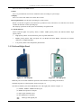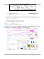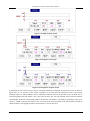
1
Multi-parameter Patient Monitor UP-8000 User Manual User Manual for Multi-parameter Patient Monitor This Manual is written and compiled in accordance with the IEC 60601-1(Medical electrical equipment Part1: General requirements for safety). It complies with both international and enterprise standards and is also approved by State Technological Supervision Bureau. The Manual is written for the current UP-8000 Multi-parameter Patient Monitor. The Manual describes, in accordance with the UP-8000 Multi-parameter Patient Monitor’s features and requirements, main structure, functions, specifications, correct methods for transportation, installation, usage, operation, repair, maintenance and storage, etc. as well as the safety procedures to protect both the user and equipment. Refer to the respective chapters for details. The Manual is published in English and we have the ultimate right to explain the Manual. Version of This User Manual: Ver1.0 August 19, 2009 All rights reserved. Marks in the Manual: Warning: must be followed to avoid endangering the operator and the patient. ☞ Note: contains some important information and tips about operations and application. Attention: must be followed to avoid causing damage to the monitor. 3502-2360003 I User Manual for Multi-parameter Patient Monitor Instructions to User Dear Users, Thank you very much for purchasing our product. Please read the following information very carefully before using this device. Read these instructions carefully before using this monitor. These instructions describe the operating procedures to be followed strictly. Failure to follow these instructions can cause monitoring abnormity, equipment damage and personal injury. The manufacturer is NOT responsible for the safety, reliability and performance issues and any monitoring abnormality, personal injury and equipment damage due to user’s negligence of the operation instructions. The manufacturer’s warranty service does not cover such faults. Do NOT operate this monitor in the circumstance where flammable gas or explosion factor exists. To ensure patient safety, do NOT place the monitor in any position that might cause it to fall on patient. The user must check that the equipment functions safely and ensure that it is in proper working condition before being used. If used with High Frequency (HF) surgery please note the positioning of Cerebral State Monitor sensor. In order to reduce the hazard of burns,the sensors should not be located between the surgical site and the electro-surgical unit return sensor. When connect this monitor with multi-parameter central monitor, the equipotential grounding terminal must be connected with the shell of central monitor, and make sure that the terminal is connected with the grounding wire reliably to make the unit which connected with this monitor and this monitor are in the same equipotential circumstance. Pay attention if the monitor is connected to a patient connected to other equipment. The total of leakage current may exceed the allowable limit and cause a possible hazard to the patient. The unit which is connected to this monitor should be in accordance with international requirements for medical device. Please shut down the monitor and remove sensors during MRI scanning, or else induced current could potentially cause burns. The monitor may affect the MRI image, and the MRI unit may affect the accuracy of monitor measurements. Although biocompatibility tests have been performed on all the applied parts, some exceptional allergic patients may still have anaphylaxis. Do NOT apply to those who suffer from anaphylaxis. All the cables and rubber tubes of the applied parts should be kept away from the patient’s cervix to prevent any possible suffocation of the patient. All the parts of the monitor should NOT be replaced at will. If necessary, please use the components provided by the manufacturer or those of the same model II User Manual for Multi-parameter Patient Monitor and standards as the accessories along with the monitor which are provided by the same factory, otherwise negative effects concerning safety and biocompatibility, etc. may be caused. Do NOT open the device cover and Cerebral State Monitor cover without authorization. Covers should only be opened by qualified service personnel. When the covers are opened, an electrical shock hazard exists which can result in serious injury to persons and instrument component damage. If the monitor falls off accidentally, please do NOT operate it until its safety and technical indexes have been carefully tested and positive testing results obtained. Before maintenance, please switch off power. This monitor is a professional medical device, can only be operated by trained personnel with qualification. Please peruse the relative content about the clinical restrictions and contraindication. When disposing of the monitor and its accessories, the local law should be followed. III User Manual for Multi-parameter Patient Monitor Table of Contents CHAPTER 1 OVERVIEW ...................................................................................................................................... 1 1.1 FEATURES ........................................................................................................................................................ 1 1.2 PRODUCT NAME AND MODEL ......................................................................................................................... 2 1.3 SCOPE OF APPLICATION ................................................................................................................................... 2 1.4 REQUIREMENT OF OPERATING ENVIRONMENT AND INSTALLATION ................................................................ 2 1.5 NORMAL WORKING ENVIRONMENT ................................................................................................................ 2 1.6 IMPACT ON THE ENVIRONMENT AND RESOURCES ........................................................................................... 3 1.7 SAFETY............................................................................................................................................................ 3 CHAPTER 2 WORKING THEORIES OF THE MAIN UNIT ............................................................................ 4 2.1 ARCHITECTURE ............................................................................................................................................... 4 2.2 STRUCTURE ..................................................................................................................................................... 4 2.3 WORKING THEORIES ....................................................................................................................................... 4 CHAPTER 3 INSTALLATION AND CONNECTION ......................................................................................... 6 3.1 APPEARANCE ................................................................................................................................................... 6 3.1.1 Front Panel............................................................................................................................................... 6 3.1.2 Left and Right Panel ................................................................................................................................ 7 3.1.3 Rear Panel................................................................................................................................................ 8 3.2 OVERALL INTRODUCTION OF CEREBRAL STATUS MONITOR ........................................................................... 8 3.2.1 Description of Keys ................................................................................................................................. 9 3.2.2 Introduction for Display Screen .............................................................................................................. 9 3.2.3 Setup Menu............................................................................................................................................ 10 3.2.4 Events .................................................................................................................................................... 12 3.3 INSTALLATION ............................................................................................................................................... 13 3.3.1 Opening the Box and Check .................................................................................................................. 13 3.3.2 Connecting the AC Power Cable ........................................................................................................... 13 3.3.3 Starting the Monitor............................................................................................................................... 13 3.4 CONNECTION ................................................................................................................................................. 13 3.4.1 ECG Connection .................................................................................................................................... 13 3.4.2 Blood Pressure Cuff Connection ........................................................................................................... 15 3.4.3 To connect the SpO2 .............................................................................................................................. 16 3.4.4 CSM Electrode Connection ................................................................................................................... 17 3.4.5TEMP Transducer Connection ............................................................................................................... 18 3.4.6 Battery Installation ................................................................................................................................ 18 3.4.7 Loading Printing Paper .......................................................................................................................... 18 CHAPTER 4 MONITORING SCREEN .............................................................................................................. 19 4.1 MAIN SCREEN ............................................................................................................................................... 19 4.1.1 Date and Time Setup.............................................................................................................................. 19 4.1.2 Screen Description................................................................................................................................. 20 4.2 FREEZE AND ST ANALYSIS SCREEN ............................................................................................................... 23 4.2.1 Screen Description................................................................................................................................. 24 4.2.2 Operation Instruction ............................................................................................................................. 24 4.3 MODE SELECTION SCREEN ............................................................................................................................ 25 4.4 SPO2 DATA LIST SCREEN ............................................................................................................................... 25 IV User Manual for Multi-parameter Patient Monitor 4.4.1 Screen Description................................................................................................................................. 26 4.5 BLOOD PRESSURE DATA LIST SCREEN .......................................................................................................... 26 4.5.1 Screen Description................................................................................................................................. 26 4.6 GRAPHIC TREND SCREEN .............................................................................................................................. 27 4.6.1 Screen Description................................................................................................................................. 27 4.6.2 Operation Instruction ............................................................................................................................. 30 4.7 RECALL SCREEN ............................................................................................................................................ 30 4.8 VPC SCREEN ................................................................................................................................................. 32 4.9 SYSTEM SETUP SCREEN................................................................................................................................. 33 4.9.1 System Parameter Settings .................................................................................................................... 34 4.9.2 Printer Parameter Settings ..................................................................................................................... 34 4.9.3 ECG Parameter Settings ........................................................................................................................ 35 4.9.4 Temperature Parameter Settings ............................................................................................................ 36 4.9.5 NIBP Parameter Settings ....................................................................................................................... 37 4.9.6 SpO2 Parameter Settings ........................................................................................................................ 38 4.9.7 CSM Parameter Settings ........................................................................................................................ 38 4.9.8 Resume Default ..................................................................................................................................... 39 4.10 COLOR SETTINGS SCREEN ........................................................................................................................... 39 4.11 FILE/ARCHIVE MANAGEMENT SCREEN ....................................................................................................... 39 4.12 EVENT LIST ................................................................................................................................................. 40 CHAPTER 5 TECHNICAL SPECIFICATIONS ................................................................................................ 41 5.1 CEREBRAL STATE MONITORING .................................................................................................................... 41 5.2 ECG MONITORING ........................................................................................................................................ 41 5.3 RESP MONITORING ....................................................................................................................................... 41 5.4 TEMP MONITORING...................................................................................................................................... 42 5.5 NIBP MONITORING ....................................................................................................................................... 42 5.6 SPO2 & PULSE RATE MONITORING ............................................................................................................... 42 5.7 RECORDED DATA ........................................................................................................................................... 42 5.8 OTHER TECHNICAL SPECIFICATIONS ............................................................................................................. 43 CHAPTER 6 PACKAGING AND ACCESSORIES ............................................................................................ 43 6.1 PACKAGING ................................................................................................................................................... 43 6.2 ACCESSORIES ................................................................................................................................................ 43 CHAPTER 7 PARAMETERS MONITORING................................................................................................... 45 7.1 CSM MONITORING........................................................................................................................................ 45 7.1.1 The Principle for Measurement ............................................................................................................. 45 7.1.2 CSM Parameters .................................................................................................................................... 45 7.1.3 CMS Processes ...................................................................................................................................... 47 7.2 ECG/RESP MONITORING.............................................................................................................................. 47 7.2.1 How to Obtain High Quality ECG and Accurate Heart Rate Value....................................................... 47 7.3 NIBP MONITOR ............................................................................................................................................. 48 7.3.1 The Principle for Measurement of Blood Pressure ................................................................................ 48 7.3.2 Points to be Noted in Measurement of Blood Pressure ......................................................................... 50 7.3.3 Clinical Limitations ............................................................................................................................... 50 7.4 SPO2/PULSE MONITOR ................................................................................................................................. 51 7.4.1 SpO2 Monitor ........................................................................................................................................ 51 V User Manual for Multi-parameter Patient Monitor 7.4.2 Points to be Noted in SpO2 and Pulse Measuring ................................................................................. 51 7.4.3 Clinical Limitations ............................................................................................................................... 52 7.5 TEMP MONITOR ........................................................................................................................................... 52 CHAPTER 8 TROUBLESHOOTING ................................................................................................................. 53 8.1 NO DISPLAY ON THE SCREEN ........................................................................................................................ 53 8.2 EXCESSIVE ECG SIGNAL INTERFERENCE OR TOO THICK BASELINE ............................................................. 53 8.3 TROUBLESHOOTING OF CMS ........................................................................................................................ 53 8.4 NO BLOOD PRESSURE AND PULSE OXYGEN MEASURES ............................................................................... 54 CHAPTER 9 MAINTENANCE ............................................................................................................................ 55 9.1 SERVICE AND EXAMINATION ......................................................................................................................... 55 9.1.1 Daily Examination ................................................................................................................................. 55 9.1.2 Routine Maintenance ............................................................................................................................. 55 9.1.3 Battery Maintenance .............................................................................................................................. 55 9.2 CLEANING, STERILIZATION AND DISINFECTION ............................................................................................. 56 9.3 CLEANING, STERILIZATION AND DISINFECTION OF ACCESSORIES ................................................................. 56 9.4 STORAGE ....................................................................................................................................................... 57 9.5 TRANSPORTATION .......................................................................................................................................... 57 APPENDIX ............................................................................................................................................................. 58 VI Chapter 1 Overview 1.1 Features UP-8000 Multi-parameter Patient Monitor is the combination of the functions of Cerebral Status Monitor and Multi-parameter Patient Monitor, which not only can monitor anesthetic deepness related parameters (CSI, EMG, BS% etc.) during anaesthesia operation, but also can synchronously monitor patient’s physiological parameters, such as ECG, respiratory rate, NIBP, SpO2, pulse rate, body temperature etc. 12.1” high-resolution color LCD display; EEG signal is acquired with common-mode rejection and amplified by Cerebral Status Monitor (CSM) to ensure the high quality of the EEG signal. Unique algorithm eliminates the effect of artifacts during the procedure of CSI determination. CSI is the result of EEG signal analysis, and can be scaled into 0 to 100 units. Bar graph display of EMG component between 75-85Hz bandwidth; Display BS% value which is derived from the latest 30 seconds EEG signal. Adopting artifact resistance algorithm to protect EEG against exterior interference; 24-hour CSM data storage; Up to 96 hours CSI trend data; Store and recall all the setting events; CSM displays CSI, EEG, EMG, BS% etc. physiological parameters simultaneously and has CSI alarm function; Automatic analysis of 20 arrhythmia waveforms and VPC, waveform freezing function and automatic ST segment measurement and manual analysis; 100 groups of arrhythmia events’ data and the corresponding ECG, TEMP, SpO2, RESP and pulse value of each case; Storage and recall of a list of 400 groups of NIBP measurement data, as well as heart rate, body temperature, respiratory rate and SpO2/pulse rate when the measure of blood pressure is taken; Up to 10 hours store and recall ECG waveform data; High precision NIBP measuring module, good repeat capability; Unique SpO2 measuring set, which ensures the accuracy of SpO2 value and plus rate. Special SpO2 measuring device, which ensures the accuracy of SpO2 and pulse rate measures; Flexible high and low alarm limits setting function; Easy to color-code and change the color of the font, background and waveforms if need to be; Multiple interface monitoring, which enables simultaneous monitoring of several ECG User Manual for Multi-parameter Patient Monitor waveforms; Resistance against defibrillator and electrosurgical unit interference and high safety level, can be used along with cardiac pacemaker; Blood pressure may be measured in the mode of “adult/infant/neonate”, which may be selected via the menu, to better suit the adult, pediatric and neonatal patient; Built-in printer to output waveforms and text; 1.2 Product Name and Model Product name: Multi-parameter Patient Monitor Model: UP-8000 1.3 Scope of Application UP-8000 Multi-parameter Patient Monitor is multifunctional equipment designed for monitoring the comprehensive physiological parameters of patient. With the functions of real-time displaying and recording of patient’s EEG, CSI, BS%, ECG, respiratory value, body temperature value, non-invasive blood pressure value, pulse oxygen saturation value, pulse rate and other physiological parameters, it allows comprehensive analysis of physiological and pathological conditions. This equipment is intended for use in major, medium and small-sized hospitals, clinics, and health practitioner’s office. The operation should be performed by qualified professionals only. 1.4 Requirement of Operating Environment and Installation 1. This equipment should be situated in a place protected against direct sunlight, so as to prevent overheating inside the equipment. 2. Do not use this device in an environment with toxic or inflammable gas. 3. This device should be fixed on a stand or flat platforms, so as to prevent possible shock. 4. Do not use with any equipment other than those expressly permitted in these instructions. 5. When using this device with electrosurgical equipment, the user (doctor or nurse) should pay attention to the safety of patient. 6. Make sure that the equal-potential grounding terminal is grounded correctly. 7. Do not use mobile phone nearby, so as to avoid strong radiant field interference. 1.5 Normal Working Environment 1. Ambient temperature range: 10°C ~40°C 2. Relative humidity: 30%~75% 3. Atmospheric pressure: 70.0kPa ~106.0kPa 4. Power supply: a.c.100~250V 5. Power frequency: 50/60Hz 2 User Manual for Multi-parameter Patient Monitor 1.6 Impact on the Environment and Resources Low 1.7 Safety Conform to IEC 60601-1, classified as Class I, with Type BF and CF applied parts. 3 User Manual for Multi-parameter Patient Monitor Chapter 2 Working Theories of the Main Unit 2.1 Architecture The architecture of this monitor is shown as Fig.2.1. Fig. 2.1 Architecture 2.2 Structure 1. The monitor consists of the main units and the corresponding functional components (CSM accessories, ECG leads, non-invasive blood pressure cuff, SpO2 probe and temperature transducer). 2. The patient monitor has 5 measurement channels: the CSI channel, the ECG and respiration channel, the NIBP channel, the SpO2 and pulse channel, the temperature channel. 3. The patient monitor has two output channels: the networking communication port and the printer. 4. Basic parameters include: CSI, EEG, EMG, BS%, heart rate, respiration rate, NIBP, SpO2, NIBP, pulse and temperature. 2.3 Working Theories UP-8000 Multi-parameter Patient Monitor, which performs physiological parameter measurement through different modules, is a product of module design. It consists of CSM module, ECG/ respiration/temperature module, NIBP module, SpO2 module and the main unit etc. 1. Adopt wireless communication to transmit data between CSM module and CSM Monitor. 2. CSM module monitors ECG, CSI, EMG, BS% etc. waveforms and data through cerebral status accessorial unit. 3. The ECG module collects the heart rate, respiration waveforms through the ECG leads and collects the temperature data through the temperature probes as well. 4 User Manual for Multi-parameter Patient Monitor 4. The SpO2 module collects the data of pulse rate, pulse oxygen saturation (SpO2) and SpO2 volume waveform via the SpO2 probe. 5. The NIBP module collects the blood pressure data, including the diastolic, systolic and mean arterial pressure through the NIBP cuff. The cuffs are designed for adult, infant and neonate respectively, and the NIBP measurement has three modes: adult, infant and neonate. 6. The main unit consists of main board, multi-function board, and the keyboard. The multi-function board performs the data communication among the main board, ECG module, SpO2 module and NIBP module. 5 User Manual for Multi-parameter Patient Monitor Chapter 3 Installation and Connection 3.1 Appearance 3.1.1 Front Panel Figure 3.1 Front Panel 1. Power switch Press it for 3 seconds to turn on or turn off the monitor. 2. AC:AC indicator When AC indicator is on, it means this device is using mains power supply. 3. DC:DC indicator of built-in battery When DC indicator is on, it means the battery is used; when both of AC indicator and DC indicator are on, it means that this device is using mains power supply and the battery is being recharged. 4. ECG Lead Selection Click it to shift the ECG monitoring circulatory among I, II, and III, aVR, aVL, aVF and V. 5. Alarm Silence Press this key to set or activate the system alarm silence function. In the monitoring screen, press Alarm Silence key to set the alarm silent time. The time shows up on the lower left of the screen. When the alarm timer is activated, the system begins to count down and alarm when the set time has passed. The alarm silent time has four options: 2 minutes, 5 minutes, 10 minutes and 20 minutes, or the system alarm is in the alarm status. 6. Freeze Press this key to freeze ECG waveforms or the waveforms of ECG, SpO2 and RESP for ST segment analysis according to system setting. 7. NIBP 6 User Manual for Multi-parameter Patient Monitor Press it to start or stop NIBP measure. 8. Print Press it to print different waveforms of different status according to system setups. 9. Display Press it to return to the main screen from other screens. 10.Navigation knob: It is the major operating key of the system. Rotate it to the left or right to select functions or parameters. Press and release it to shift the screen and to confirm the function or other operating tips. The majority operations of this system are finished by navigation knob. 11. Alarm indicator Yellow indicator lights- low priority alarm, it blinks: middle priority alarm; red indicator blinks: high priority alarm; ☞ High priority alarm: exceeds the limits, pulse stop and suffocation. ☞ Middle priority alarm: leads and probe off, VE RONT and SVE RONT, electrodes off, artifact difference, too high impedance . ☞ Low priority alarm: other arrhythmia phenomenon. 3.1.2 Left and Right Panel Figure 3.2 the left panel Figure 3.3 the right panel Different ports are located in different positions of the monitor for operating conveniences. The built-in printer is at the left panel, shown as Figure 3.2 The cable, transducer ports and CSM Monitor are at the right panel, shown as Figure 3.3. (1) TEMP1, TEMP2: TEMP transducer port (2) NIBP: blood pressure cuff port (3) SpO2: SpO2 transducer port (4) ECG/RESP: ECG lead port With Type BF applied part 7 User Manual for Multi-parameter Patient Monitor With Type CF applied part and applicable during the defibrillator is used Caution! Please read the manual for details. 3.1.3 Rear Panel Figure 3.4 Rear panel The following ports are at the rear panel of the monitor. (1) MONITOR: external display port (2) NET: serial port for software upgrade (3) : Equal potential grounding port (4) “FUSE T3.15 A”: fuse holders;fuse specification:T3.15AL/250V Φ520mm. (5) AC100~250V: Power supply socket (6) S/N: Serial number (7) Nameplate 3.2 Overall Introduction of Cerebral Status Monitor 8 User Manual for Multi-parameter Patient Monitor 3.2.1 Description of Keys 3.2.2 Introduction for Display Screen The CSM always starts with display A Switch between display A, B, C and D by pressing the Display key (7). 1. Display Mode A Main information window with CSI, BS%, EMG%, SQI%, operation time and battery information. Fig. A 2. Display Mode B CSI trend curve with event markers and BS curve. EMG% is displays as a bar in the right panel. Operation time and numeric value of the actual CSI and BS%. The time scale for the trend curve is 5.27 minutes and each tag is 60 seconds. 9 User Manual for Multi-parameter Patient Monitor Fig. B 3. Display Mode C Sensor impedance, CSI, BS% and operation time. When display C is active, the sensor impedance is updated every 60 seconds. Press Display key (7a) firmly for immediately impedance update. Fig. C 4. Display Mode D CSI trend histogram with 5-minute interval showing average, lowest and highest CSI values within the interval. EMG% is shown in the display as a bar in the right-hand side. Operating time and numerical value for current CSI and BS%. The time scale for the histogram graph is 180 min. The interval between each tag is 60 min. The high-low bar in the current time interval (high-low bar to the far right) is updated dynamically. Fig. D 3.2.3 Setup Menu General menu structure and menu selections Top Menu 10 User Manual for Multi-parameter Patient Monitor How to select menu settings from Display Mode 1. Remove battery lid. 2. From any Display Mode, press any arrow on the Control key (9). 3. The top menu appears. 4. Note: The last menu used is chosen. How to set parameter values 1. Press the Control key (9a) to select menu. 2. Press the Control key (9b) to enter submenu. 3. Press the Control key (9a) to select parameter. 4. Press the Control key (9b) to highlight parameter value. 5. Press the Control key (9a) to select parameter value. 6. Press the Control key (9b) to store setting or (9c) to cancel the selection and return without any change. 7. Press the Control key (9c) to go back in one menu level steps. If the Control key has not been activated in 20 sec. the CSM returns to Operation Display Mode. Note: The change of settings will only be stored for future use after returning to Operation Display Modes. Settings Menu Parameter Description Values(Default) High Alarm Selects the CSI Alarm High Option ON/OFF(OFF) Low Alarm Selects the CSI Alarm Low Option ON/OFF(OFF) High Limit Selects the CSI High Alarm Level 2-99(60) Low Limit Selects the CSI Low Alarm Level 1-98(40) Language Select device language English Contrast Select display contrast 10-30(20) Alarm Config RF interface Auto Link Select radio link active. If turned OFF the link is completely inactive. Active Auto Link Option Device Information: Select Submenu. 11 ON/OFF(OFF) Active/Inactive(Active) User Manual for Multi-parameter Patient Monitor Info: Serial number Firmware version CSI version AD version Link: - indicates no CSM Link connected. If CSM Link connected the CSM Link serial number and software version will be shown. Log: Serial number. #1 total no. of CSM sessions. #2 total no. running hours 3.2.4 Events Pressing the Set Event key (6) results in a continuously numbered event with no type description. Pressing the Event Type key brings up the following selection menu: The following option can be selected: Induction, Intubation, Maintenance, Surgery, Injection, Note, End Maintenance, and Movement. When the desired option has been selected, press the Set Event key (6) to confirm. If no selection is made within 5 seconds the system returns to the current Display Mode. Only the event numbers visible on Display Mode B. Event names will only be recorded when using the CSM Link option. 12 User Manual for Multi-parameter Patient Monitor 3.3 Installation 3.3.1 Opening the Box and Check 1. Open the packaging, take out monitor accessories from the box carefully and place it in a safe stable and easy to watch position. 2. Open the users’ manual to sort the accessories according to the packing list. Inspect the accessories for any mechanical damages Check all the exposed leads and inserted accessories Please contact the local dealer or our company in case of any problems. We are to offer you the best solution for your satisfaction. 3.3.2 Connecting the AC Power Cable Connecting procedures: Make sure that the AC power supply is 100-250Vac, 50/60Hz. Use the power cable prepared by the manufacturer. Insert one end of it to the power port of the monitor and the other end to the grounded three-phase power jack. Connect the monitor to the grounding port with the provided ground cable. Caution: ensure that the monitor is grounded correctly. The provided battery of the monitor must be recharged after transportation or storage. So if the monitor is switch on without being connected to the AC power socket, it may not work properly due to insufficient power supply. 3.3.3 Starting the Monitor The system performs self-detection and enters initial display after switch on the monitor, and the orange alarm indicator blinks to inform that the user can begin operating it. Check all the applicable functions to make sure that the monitor works normally. If the built-in battery is applied please recharge it after using the monitor to ensure sufficient power storage. Do not use the monitor to monitor the patient if there are indications of damage or reminders of error. Start the monitor again 1 minute later after it is switched off. 3.4 Connection 3.4.1 ECG Connection ECG measurement is to collect the ECG signal via the ECG electrodes. Electrode connects the patient and the lead. The lead connects the monitor. The locations of the electrodes are very important for obtaining accurate ECG 13 User Manual for Multi-parameter Patient Monitor signals. 1. Connect the cable to the right-panel connector marked with the ECG icon. 2. Select electrodes to be used. Use only one type of electrode on the same patient to avoid variations in electrical resistance. For ECG monitoring, it is strongly recommended to use silver/silver chloride electrodes. When dissimilar metals are used for different electrodes, the electrodes may be subject to large offset potentials due to polarization. Using dissimilar metals may also increase recovery time after defibrillation. 3. Prepare the electrode sites according to the electrode manufacturer’s instructions. The locations of the electrode are in the following Figure: Figure 3.5 Electrode Location Note: If skin rash or other unusual symptoms develop, remove electrodes from patient. 4. After starting the monitor, if the electrodes become loose or disconnected during monitoring, the system will display “LEAD OFF” on the screen to alarm the operator. 5. The ECG leads and their corresponding locations are as follows: Symbol RA LA LL RL C (V) Chest electrode C1(V1) C2(V2) C3 (V3) C4 (V4) C5 (V5) C6 (V6) Position The intersection between the centerline of the right clavicle and Rib 2 The intersection between the centerline of the left clavicle and Rib 2 Left part of the upper abdomen Right part of the upper abdomen The electrodes are placed in different places, the different lead forms will display. It might not display ECG wave with 3 leads. The 5 leads should be used to have ECG wave. Safety Instructions for ECG Monitoring UP-8000 Multi-parameter Patient Monitor can only be equipped with ECG leads provided by our company; using ECG leads supplied by other companies may cause improper performance or poor protection while using defibrillator. Electric parts of electrodes, leads and cable are forbidden to contact any other conductive parts (including ground). UP-8000 Multi-parameter Patient Monitor can resist against defibrillator and electrosurgical unit. Readings may be inaccurate for a short time after or during using defibrillator or electrosurgical unit. 14 User Manual for Multi-parameter Patient Monitor Transient caused by cable circuitry blocks while monitoring may be similar to the real heartbeat waveform, as a result resistance heart rate alarm rings. If you put the electrodes and cable in proper places according to this manual’s instructions and the instructions for using electrode, the chance of this transient occurring will be decreased. To the patient with pacemaker, due to that this device has been designed to provide resistance to pacemaker signal interference, generally the pacemaker pulse is not counted in heart rate measurement and calculation, but when the cycle time of pacemaker pulse is over 2ms, it may be counted. In order to reduce this possibility, observe the ECG waveforms on the screen carefully and do NOT rely entirely on the heart rate display and alarm system of this monitor when monitoring this kind of patients. Besides the improper connection with electrosurgical unit may cause burns, the monitor may be damaged or arouse deviations of measurement. You can take some steps to avoid this situation, such as do NOT use small ECG electrodes, choosing the position which is far away from the estimated Hertzian waves route, using larger electrosurgical return electrodes and connecting with the patient properly. ECG leads may be damaged while using defibrillator. If the leads are used again, please do the functional check first. 3.4.2 Blood Pressure Cuff Connection 1. Connect the cable to the right-panel connector marked with the NIBP icon. 2. Select a cuff of appropriate size according to the age of the subject. Its width should be 2/3 of the length of the upper arm. The cuff inflation part should be long enough to permit wrapping 50-80% of the limb concerned. See the table below for the dimensions: Note: The size of the cuff selected should suit the subjects while measuring. Cuff Model Arm Circumference Cuff Width Neonate Cuff 6.0cm~9.5cm 3cm Small-sized Infant Cuff 6cm~11cm 4.5cm Middle-sized Infant Cuff 10cm~19cm 8cm Large-sized Infant Cuff 18cm~26cm 10.6cm Adult Cuff 25cm~35cm 14cm Prior to use of the cuff, empty the cuff until there is no residual air inside it to ensure accurate measurement. When putting on the cuff, unveil and wrap it around the upper arm evenly to appropriate tightness as shown below. Figure 3.6 Cuff Position When unplugging the cuff, hold the head of the connector and pull it out. 15 User Manual for Multi-parameter Patient Monitor Safety Instructions for NIBP Monitoring When taking the measure of an infant or neonate’s (less than 10 years old) blood pressure, do NOT operate in the adult mode. The high inflation pressure may cause lesion or even body putrescence. It is recommended to take the blood pressure measurement manually. Automatic or continuous measurement should be used at the presence of a doctor/nurse. NIBP monitoring is prohibited to those who have severe hemorrhagic tendency or with sickle cell disease, or partial bleeding will appear. Do NOT bind NIBP cuff on limbs with transfusion tube or intubations or skin lesion area, otherwise, damages may be caused to the limbs. Pay attention to the color and sensitivity of the limb when measuring NIBP; make sure the blood circulation is not blocked. If blocked, the limb will discolor, please stop measuring or remove the cuff to other positions. Doctor should examine this timely. Do NOT twist the cuff tube or put heavy things on it. 3.4.3 To connect the SpO2 SpO2 probe is very delicate equipment. Please follow the steps and procedures in operating it. Failure to operate it correctly can cause damage to the SpO2 probe. Operation procedure: 1. Connect the SpO2 probe to the right panel’s jack labeled “SpO2”. When unplugging the probe, be sure to hold the head of the connector and pull it out. 2. Insert one finger into the probe (index finger, middle finger or ring finger with proper nail length) according to the finger mark on the probe, shown as below. Figure 3.7 Demonstration for SpO2 probe The scenario above will cause inaccurate reading or no readings during SpO2 measurement. Safety Introductions for SpO2 Monitoring Continuous use of fingertip SpO2 sensor may result in discomfort or pain, especially for those patients with microcirculatory problem. It is recommended that the sensor should NOT be applied to the same finger for over two hours. SpO2 measuring position must be examined more carefully for some special patient. Do NOT 16 User Manual for Multi-parameter Patient Monitor install the SpO2 sensor on the finger with edema or fragile tissue. Do NOT put the SPO2 sensor and pressure cuff on the same limb, otherwise the NIBP measuring will affect SpO2 measuring and cause the alarm error. Do NOT use the damaged SpO2 sensor. Please do not allow the cable to be twisted or bended. Please do not use nail polisher or other cosmetic product on the nail. The fingernail should be of normal length. The SpO2 sensor can not be immerged into water, liquor or cleanser completely, because the sensor has no capability of waterproofness. SpO2 Monitor Interrupt Indication After power on or during patient monitoring, if the third channel displays no waveforms, please stop patient monitoring immediately, and remove SpO2 sensor (main screen see section 4.2) and refer to chapter 8 to carry through troubleshooting. If in doubt, please contact the dealer or the manufacture. 3.4.4 CSM Electrode Connection Clean and dry-abrade skin to ensure low sensor impedance. Mild soap and Water is recommended as a skin cleanser. Note: Alcohol is not recommended as a skin cleanser; it leaves a film layer that may cause high sensor impedance. If alcohol is used, ensure 30-second dry time. Dry-abrading the skin gently with a dry wash cloth, gauze, or skin preparation product is helpful to remove the non-conductive skin layer. Positioning of the three monitor sensors is shown below. The advanced signal processing of the monitor ensures that a deviation in the positioning of the sensors up to 2 cm (0.78 in) has no significant influence on the index. However, it is recommended to place the sensors on an area of the skull where only a few muscle fibres are present in order to achieve the best quality signal. Caution: Make sure no part of the sensors is in contact with any other conductive parts including earth/ground. If skin rash or other unusual symptoms develop, remove sensors from patient. Change sensors every 24 hours to check skin integrity. Note: Once the sensors have been secured on the skin, attach the color-coded wires on the patient cable to appropriate sensor. Shown above is a left sided setup; right sided is also acceptable. Place sensors at the side farthest from the surgical area. 17 User Manual for Multi-parameter Patient Monitor The conductive parts of sensors and their connectors, including the neutral sensor, should not contact other conductive parts including earth. The monitor will not render accurate readings when used on patients with severe neurological disorders and patients under 2 years of age. The use of pacemakers might cause either long periods of artefacts or elevated CSI values. 3.4.5TEMP Transducer Connection Multi-parameter Patient Monitor has two TEMP transducers to measure different body temperature. Connecting methods: 1. Attach the transducers to the patient firmly; 2. Connect them to TEMP1” or “TEMP2” on the right panel. Note: When unplugging the probe, be sure to hold the head of the connector and pull it out. 3.4.6 Battery Installation 1. Make sure that monitor doesn’t connect to mains power supply and stays in switch-off status. 2. Open the battery cover, insert the battery into any slot of battery compartment, and pay attention to the instruction of polarity direction in the compartment. Do not reverse the battery. 3. Move baffle plate with hand to fasten the battery. 4. Remove the battery cover. (According to your need, you can insert one more storage battery to prolong using time.) Please take out the battery from battery compartment, if it won’t be used for a long time. 3.4.7 Loading Printing Paper This description is for loading paper for the built-in printer. Operation procedures: 1. Press both “OPEN” notches with force on printer shield with two thumbs to open it. 2. Move the tab of rubber roller lock at the left 90°upwards to unlock it. 3. Cut one end of the paper into triangle, and load the paper from the underside of the rubber roller. 4. Turn the roller clockwise to get the paper rolled, and put the paper roll into the compartment. 5. Pull the paper out of paper slot on the shield. 6. Move the tab of the rubber roller lock 90° downwards to lock it. 7. Put the shield back in position and secure it. 18 User Manual for Multi-parameter Patient Monitor Chapter 4 Monitoring Screen 4.1 Main Screen 4.1.1 Date and Time Setup Instead of entering into monitoring screen, it shows the date and time setting screen immediately after the monitor is started, shown as Figure 4.1: Figure 4.1 Date and Time Setup The system will stay on this screen for 10 seconds. If you do not rotate the navigation knob within this period, the screen will enter into the Main Screen. Follow the steps below to set date and time. Step 1: Rotate Navigation Knob, move the gray cursor to “Edit”. Step 2: Press the knob, and then gray cursor stays on the Year of the date. Press the knob again and the gray cursor becomes highlighted. Rotate the knob left or right to increase or decrease the year value. Step 3: When the Year is set, press the knob to move the gray cursor to the Month of the date. Step 4: Repeat Step 2 and Step3 to adjust the Year, Month, Date, Hour and Minute. Step 5: If you have finished adjusting the date and time, press the knob and rotate the knob to move the cursor to “Save”, press it to save the settings. Then move the cursor to “Exit”, press it to exit the date and time setting screen, meanwhile enter into the main screen shown in Figure4.2. The system is initialized and enters into Main Screen where monitoring and system operation are performed. (shown in Figure 4.2) 19 User Manual for Multi-parameter Patient Monitor 4.1.2 Screen Description Figure 4.2 Main Screen Border area Figure 4.3 Status/Information Area ”: shows the alarm is ON,and shows the alarm OFF, the numbers after is the “Alarm time when the alarm is off. The alarm activates automatically after the system finishes counting down. ID: The patient ID. The patient ID can be entered or changed in the archive management window. “ADUL”: The type of the monitor subject. There are three modes available: “Adult”, “Infant” and “Neonate” (Adult for adult patient, Infant for pediatric patient, Neonate for neonate patient). : battery power indicator; when the indicator is yellow and displays only one “grid”, it means there is a little battery power left. When the indicator turns red and blinks, as well as less than one “grid” displayed, meanwhile, the system alarm will be on to remind the battery shortage. Please connect the device to the mains power supply in time to ensure the normal use of this monitor, and the battery will be recharged. When the battery power is full, battery power indicator displays full grid. During recharging, the grids in the battery indicator are rolling circularly. (Note: This function is optional, and needs hardware support.) “2007-04-25 08:50:15”: System current time and date. The system time and date can be set during the system start-up when the screen displays the time and data setups. The current figure shows the time and date of April 25th, 08:50:15, 2007. “Exceeding CSI limit”: System indication or description for the current status. 20 User Manual for Multi-parameter Patient Monitor Waveform area 1st Waveform: The first waveform is ECG waveform for lead II. Any lead can be selected via “ECG Lead” key. 2nd Waveform: the waveform for 1st channel. 3rd waveform: SpO2 waveform 4th waveform: respiration waveform 5th waveform: CSM waveform, the latest 4 minutes CSM trend waveform. This area is operation area, detailed operation see chapter 4.3 Mode Selection Screen. Data area Figure 4.4 Heart Rate Data Area “HR”: The currently displayed heart rate. The 60 on the right side is the heart rate measured. “bpm”:The heart rate unit, bpm = beat per minute. “ ”: The heart beating symbol. Its flashing corresponds to the R wave of the ECG waveform. The speed is the same with the heart rate. “ST+0.098mv”: The measured milli-volts value during ST measurement. Figure 4.5 Blood Pressure Data Area “NIBP”: The blood pressure type labels and the measured value. “08:49”: The time of NIBP measuring “Adult”: NIBP measurement mode. The subject is adult. “mmHg”: Blood pressure value unit: mmHg/kPa “00:01:34”:The NIBP measurement mode. 21 User Manual for Multi-parameter Patient Monitor Figure 4.6 SpO2 and Pulse Rate Data Area “SpO2”: SpO2 label,The “99%” is the current SpO2 value measured. “PR”: Pulse rate label. The value “69” on the upper right shows the pulse rate value. “ ”: SpO2 strength bar. Figure 4.7 RR Data Area “RR”: Respiration Rate: The rpm after that is the unit of respiration, i.e., respiration per min. When no RR value detected to display, this area displays “Searching” “X2”: Respiration gain(amplification) : “X1/2” half of the basic waveform “X1” basic waveform “X2” Twice the size of the basic waveform. “X4” 4 times of the basic waveform Figure 4.8 CSM Parameter Values Area 22 User Manual for Multi-parameter Patient Monitor Figure 4.9 Temperature Data Area TEMP1/2: Temperature label. The value below“36.7, 37.2” are the temperature values. “℃”: Body temperature unit. TD: the absolute value in temperature between TEMP ℃ is Celsius; Details see Chapter and ° F4.9.4. is Fahrenheit. Ⅰ and TEM PⅡ. ☞ The printing is determined by the option of CSM item on Print Setup Screen if you press the Print Key: When the option is “OFF”, press the Print key in the main screen, a channel of ECG waveforms and the channel of “Wav2” will be printed. When the option is “PARA”, CSM trend will be printed; when the option is “EEG”, EEG waveform will be printed. 4.2 Freeze and ST Analysis Screen In the main screen, press the Freeze key to freeze the first channel ECG waveform or EEG waveform or the upper five waveforms on the screen (details see Chapter 4.2.1), as shown in Figure 4.10. Figure 4.10 Frozen Screen 23 User Manual for Multi-parameter Patient Monitor 4.2.1 Screen Description Freezing, ST segment analysis screen is similar with the main screen, except the waveforms are frozen. For example, the Figure 4.11 is a portion of the frozen waveform. The symbols on the screen were described briefly on the screen. Figure 4.11 (a) ECG Frozen Waveform Figure 4.11(b) EEG Frozen Waveform When the system setting for the freezing waveform is “ALL”, the Freeze key will freeze the upper 5 waveforms. 4.2.2 Operation Instruction The operation can use the Navigation Knob to analyze the ST segment waveform, i.e. measuring the difference between the ST segment value and the referenced value. The value is displayed after the measure on “ST + 0.000 mV”. The operation is carried out in 4 steps. First, rotate the Navigation Knob to move the base point (the red cross) horizontally to base line point (the base line is between the Q wave and the P wave). At this point, the frozen screen shows “ST+0.xxx mV, Set Base, Dirc Hor” Second, press the Navigation Knob. The screen shows “ST+0.xxx mV, Set Base, Dirc Ver”. Then rotate the knob to move the base point vertically to the base line point. Third, press the Navigation Knob again. The screen shows “ST+0.xxx mV, Set ST, Dirc Hor”. Rotate the knob to move the ST point (the yellow cross) horizontally to the point to be measured on the ST segment. 24 User Manual for Multi-parameter Patient Monitor Last, press the Navigation Knob again. The screen shows “ST+0.xxx mV, Set ST, Dirc Ver”. Rotate the knob to move the ST point vertically to the point to be measured on the ST segment. One the main screen allows pressing the Freeze key to enter the ST segment analysis screen. NOTE: The S point is the end point of S wave, and the T point is the start point of T wave. ☞ The printing is determined by the option of CSM item on Print Setup Screen if you press the Print Key, refer to Chapter 4.9.2 Printer Parameter Settings for details. 4.3 Mode Selection Screen Press the Navigation Knob in the main screen as shown in Figure 4.2, the operating area shows the mode selection screen, as shown in Figure 4.12. Figure 4.12 Mode Selection Screen In the mode selection screen, rotate the knob to move the gray cursor to the corresponding screen. Press the knob to enter the screen of SpO2 List, NIBP List, TREND, RCALL, VPC, SETUP, COLOR, FILE, and EVENT. Start from Chapter 4.4 these modes are described in turn. Press “Exit” or Display Key to exit from this screen. ☞ The printing is determined by the option of CSM item on Print Setup Screen if you press the Print Key, refer to Chapter 4.9.2 Printer Parameter Settings for details. 4.4 SpO2 Data List Screen Move the gray cursor to SpO2 List in the mode selection screen, and press Navigation Knob to enter into SpO2 data list screen, displays in the same position shown as Figure 4.13. Figure 4.13 SpO2 List 25 User Manual for Multi-parameter Patient Monitor 4.4.1 Screen Description In the SpO2 list title bar, the front color of SpO2, PR is the same with SpO2 parameters’ and other front color is white. The operation on the data listing is simple. Using the Navigation Knob allows the user to scroll the list up and down. When rotating the knob anti-clockwise, the list scrolls upward (i.e. use the ↑ arrow to scroll the data). When rotating knob clockwise, the list scrolls down (i.e. use the ↓ arrow to scroll the data). Please note that when the groups of data are less than 11, the Navigation Knob can not be used to scroll up or down the listing. Up to 15 groups of the latest data can be printed each time when printing SpO2 list and the printing data is the SpO2 list on current screen. Rotate the knob to display the next screen and then press the Print key to perform printing, the next page of SpO2 list will be printed. All the parameters in the SpO2 data list are corresponding to the time when the SpO2 measurements were taken. There is only one record every 4 seconds. ☞ Press the Print Key to print SpO2 list. 4.5 Blood Pressure Data List Screen Move the gray cursor to NIBP List in the mode selection screen, and press Navigation Knob to enter into NIBP data list screen, displays in the same position shown as Figure 4.14. Figure 4.14 NIBP List 4.5.1 Screen Description The NIBP list screen is similar with the SpO2 data listing screen. The difference is the title bar colors. In the NIBP list title bar, the front color of NIBP is the same with NIBP parameters’ and other front color is white. All the parameters in the NIBP list are corresponding to the time when the NIBP measurements were taken. When the NIBP measurement is taken successfully each time, the NIBP list will be updated, and the latest measured data is in front of the list. The all operations is similar to the SpO2 data listing screen, please refer to the previous chapters. ☞ Press the Print Key to print NIBP list. 26 User Manual for Multi-parameter Patient Monitor 4.6 Graphic Trend Screen 4.6.1 Screen Description Move the gray cursor to “TREND” in the mode selection screen, and press Navigation Knob to enter into trend screen, displays in the same position shown as Figure 4.15. Finger 4.15 Trend Menu Screen This is the graphic trend selection screen, i.e. Trend Menu screen. If you want to enter one of the trend graphs, the procedures are: rotate the knob, move the cursor to one of the parameter. For example, from the left to right, we are entering “Heart Rate”, “ST Segment”, “Temperature”, “NIBP”, “SpO2”, “Respiration Rate”, “CSI” trend graphs. Their screens are described in the following figures. Figure 4.16 Heart Rate Trend Figure 4.16 is the ECG trend graph. There are 3 options on the right of the graph, as described below. The “12h” on the top shows the trend graph time. Move the cursor to the trend time, press the knob and rotate it, and the trend graph time will change to 24h or 96h, which changes the horizontal coordinates to be 24 hours or 96 hours. The corresponding trend graph also changes to 24 - hour trend or 96- hour trend. After choosing “OBSE”, the trend graph display a triangle and a vertical line, a moving ruler mark that can be moved by rotating the knob. As shown in the figure, when you move the mark to a specific point, the data area below the graph will display the time, and its corresponding heart rate, respiration rate, SpO2, temperature Ⅰ , temperature Ⅱ. W hen r rule is that the initial step is 1, after moving it towards the same direction 5 times, the interval becomes 5, and with 5 more steps the interval becomes 10, then 20 and 40. No matter what the interval is, as long as you move 27 User Manual for Multi-parameter Patient Monitor towards the other direction, the interval becomes 1 of the other direction. Therefore, it is very easy to find the time you are looking for. In this screen, press the DISP key to exit and return to the initial screen. Rotate the knob to move the gray cursor to the others parameter field, and then press the knob, the screen will enter into trend monitor screen of this parameter. Please note that the maximum value on the vertical coordinates of the ECG is 150, not the value of ECG high limit 300. The graph is scaled down for better view of the waveforms. When the ECG value exceeds 150, the vertical coordinate’s maximum value will automatically change to 300. That is to say, the vertical axis value 0-75-150 will change to 0-150-300 automatically if the ECG value exceeds 150. When system gets reset or the patient ID is changed, the vertical coordinate will return to its original value of 0, 75, and 150. Other changes of vertical coordinate value in other trend graph are similar to that of ECG. The Trend graph shows parameter value of the current time. For example, in the 12 hours trend graph, when the monitoring time exceeds 12 hours, the data 12 hours ago will be move out of the graph. This ensures the screen always display the current data for review. The data moved out of the graph is not deleted but is just hidden temporarily. When the time frame changes from 12 hours to 24 hours (while the monitoring time is less than 24 hours), the complete set of data will display. Other trend graph follows the same rule. The respiration rate, body temperature and other trend graph are similar to that of ECG’s and we will not cover them in detail again. Please note that for those trend graphs, the horizontal coordinate is the number of times the blood pressure measured in stead of time. The CSI trend graph is different, so details see the introduction of CSI trend graph. Figure 4.17 ST Graphic Trend Figure 4.18 Body Temperature Graphic Trend 28 User Manual for Multi-parameter Patient Monitor Figure 4.19 NIBP Graphic Trend Figure 4.20 SpO2 Trend Graph Figure 4.21 Respiration Graphic Trend In trend menu screen, move the gray cursor to CSI field, and then press the knob to enter trend screen, as shown in Figure 4.22. The“0, 50,100” on the vertical coordinates is the CSI value, the maximum value is 100 and the minimum value is 0. This coordinate value is unalterable. When the interval of CSI value is 10s, the trend time of CSI trend graph will be 80 minutes. The 4 four interval values 10s, 20s, 40s and 80s can be selected, and their corresponding trend time of CSI trend graph are 80 minutes, 160 minutes, 320 minutes, 640 minutes. Move gray cursor to “OBSE” and press the knob to view CSI value in the time of monitor trend. The detailed operation is similar with ECG trend graph operation, and will not be covered it any more. 29 User Manual for Multi-parameter Patient Monitor Figure 4.22 CSI Graphic Trend 4.6.2 Operation Instruction Rotate the Navigation knob to select parameter and press it to view trend graph. Choose “OBSE” to view all the parameters at some time. The value “8h”field can be selected as 8h, 24h, and 120h. Move the cursor to “Exit” button and press it, or just press the DISP key to exit and return to initial screen. Note: In the temperature trend graph, the Temperature 1 is dotted in white and Temperature 2 is dotted in green. ☞ Press the Print Key to print the current graphic trend. 4.7 Recall Screen Move the gray cursor to “Recall” in the mode selection screen, and press Navigation Knob to enter into Recall trend screen, displays in the same position shown as Figure 4.23. Figure 4.23 Recall List In this screen ECG waveform recall or CSI and EEG waveform recall can be selected, we will cover the each button function in the recall list screen. ECG button: For selecting the type of recall data. Two options: CSM and ECG. Choose CSM button and then press the knob to shift between CSM and ECG. If the option is “CSM”, the CSI trend and EEG waveform recall will be displayed; If the option is “ECG”, the ECG waveform recall will be displayed and the list area will be the ECG recall list screen (as shown in Figure 4.25). Generally the recall record is saved every one hour, if the patient is changed less than one hour; this piece of record will be saved as a separate record. 30 User Manual for Multi-parameter Patient Monitor Recall: press the recall button, the first record of recall list turns to green, rotate the knob to select a record, and then press the knob to perform data recall, the recalled waveform and data will be displayed in the second channel. In CSM recall screen, rotate the knob to view CSM trend and EEG waveforms corresponding to this point, rotate the knob also can shift the staff toward right/left, the corresponding BS, EMG and SQI value will appear above the waveform. The EEG waveform area can display 5seconds EEG waveform from sometime. When rotating Navigation Knob to move the mark, the moving interval is a changing value. The rule is that the initial step is 1, after moving it towards the same direction 5 times, the interval becomes 5, and with 5 more steps the interval becomes 10, then 20, 40 and 80. The recalled EEG waveform is shown as Figure 4.24. Figure 4.24 CSM Recalled Waveform Figure 4.25 ECG Recall List Rotate the Navigation Knob to move forward or backward to review the waveform. Press the Navigation Knob to exit the waveform recall and return to the initial waveform recall screen. During waveform recall, the system not only displays the current recalled waveform, but also displays the lead status, gain and filter type of the waveform and time, as shown in Figure 4.26 Waveform Recall. Figure 4.26 Waveform Recall Rotate the Navigation Knob to move forward or backward to review the waveform. Press the Navigation Knob to exit the waveform recall and return to the initial waveform recall screen. 31 User Manual for Multi-parameter Patient Monitor During waveform recall, the system not only displays the current recalled waveform, but also displays the lead status, gain and filter type of the waveform and time, as shown in Figure 4.25 Waveform Recall. HIST: press the key to shift between the history key and current key. Press HIST and the recall list on the left displays the history data list. Press the Current, the recall list on the left side displays the current one. When entering the recall screen, the system defaults the current one. ECG Record: up to 10 hours the latest ECG waveform and other related information; CSM Record: up to 24 hours the latest ECG waveform record; The leads, gain etc. parameter values saved in ECG is in accordance with system parameter settings. Delete: press this key, and the selected record in the recall list becomes green. Rotate the Navigation Knob to choose the reviewed record that is to be detected, press it, release it 2 seconds later, and then the record is deleted. The current record cannot be deleted, or else the system will exit from deleting status automatically. Exit: press this key to return to the system setup menu. ☞ If on ECG waveform recall screen, press Print Key to print the recalled data list. If a piece of record is chosen, press Print Key to print the current ECG waveform and the recalled waveform on the Waveform Recall Screen. ☞ If on CSI and EEG waveform recall screen, press Print Key to print the recalled data list. If a piece of record is chosen, press Print Key to print CSI recalled trend or CSM recalled Waveform which is determinded by the option of of CSM item on Print Setup Screen. If option of of CSM item on Print Setup Screen is off, no data shall be printed. 4.8 VPC Screen Move the gray cursor to “VPC” and press Navigation Knob to enter VPC screen, shown in Figure 4.27. Figure 4.27 VPC Screen 32 User Manual for Multi-parameter Patient Monitor Start: This button is used to start and end the system arrhythmia detection. The default is OFF. When the VPC is not ON, the learn key is disabled. Press this key and the system enters learning mode. The Start changes to End. Press it again to end the learning. When “Learn” key change to yellow from gray, it indicates the learning has finished. After the arrhythmia detection is begins, the system will automatically detect the arrhythmia waveforms. If arrhythmia is detected, the arrhythmia waveform will be displayed in the second ECG channel, shown in Figure 4.27 When the system get reset or the patient has change, the arrhythmia needs to be re-learned. Learn: Because the arrhythmia detection is based on the normal ECG waveform at the same speed and same amplitude, when the patient changes, or the arrhythmia detection is incorrect, the arrhythmia needs re-learn. To better use the learn function, it is recommended to use a good ECG waveform to learn during the monitoring. View: Press this key, and the selected record in the VPC list, which is to be reviewed, becomes the green. Rotate the Navigation Knob to choose the record and display the corresponding waveform in the second ECG channel. Press the knob again to exit. Exit: press this key to exit the arrhythmia detection screen and return to the system menu. During monitoring, if arrhythmia is detected, the system will alarm. The VPC alarm is system default and does not need setup. During arrhythmia detection, incorrect detection might occur if the non-ECG waveforms (e.g.; square wave and triangle wave) appear. Before start 1mV testing, please turn off the arrhythmia detection. During arrhythmia detection, the arrhythmia module is very important. The system requires a group of stable ECG waveforms. If the system detects the arrhythmia incorrectly, please relearn arrhythmia by pressing “Learn” button and capture correct template. ☞ Press print key to print the arrhythmia data list. If a piece of record is chosen, press print key to print the current ECG waveform and arrhythmia waveform on the VPC Screen. 4.9 System Setup Screen In the Mode Selection screen, move the cursor to the “SETUP”, and press it to enter system setup screen, shown in Figure 4.28. Figure 4.28 Parameter Settings To set up the system parameter, rotate the Navigation Knob to move the cursor to the corresponding button, and press it to perform corresponding settings. 33 User Manual for Multi-parameter Patient Monitor The Default button is used to resume default vales of parameter, but the Document information and its data will not be changed. We will cover the functions of each button below. ☞ On any parameter setting screen, press print key to print parameter settings. 4.9.1 System Parameter Settings Type: The subject being monitored, this can be selected among Adult, Infant and Neonate. Adult: the subject is adult. Infant: the subject is pediatric patient. Neonate: the subject is neonate. The default is “Adult” When changing the patient type, the system will perform the alarm settings, NIBP settings initializations. Please pay special attention to the patient type before starting the monitoring. It is forbidden to use Adult type on the infant patient. Doing so can cause serious injury. Mode: Monitor mode selection. The Real Time shows the real time waveform, i.e. normal monitoring state. The DEMO shows the demo waveforms. In the demo state, all the signals and data are generated from the patient monitor for demo and testing purpose. The default is “Real Time” Lang: the current language used, which can be selected by the user. There is no default for this setting. However, the setting can be saved. Fill: When the fill setting is ON, the display fills the volume for the SpO2 and Respiration. When it is OFF, the system displays the line graph. The default is OFF. Frze: Pressed the key to freeze the selected waveform. The options are “All” and “ECG”. When ECG is selected, the system only freezes the ECG waveform. When “All” is selected, the system freezes all the waveforms including ECG, SpO2, and Respiration. The factory default is “ECG” Disp2: The screen can display the observe screen or seven ECG waveforms on the same screen. VOL: The sound volume. The maximum volume is 7 and minimum is 0, i.e. no sound. The default is 5. Key: If the setting is ON, the press of the button will generate a keystroke sound. The factory is ON. BP source: Blood pressure value display option, the default is “NIBP”.(not adjustable) 4.9.2 Printer Parameter Settings Figure 4.29 Printer Parameter Settings 34 User Manual for Multi-parameter Patient Monitor Printer: Printer switch. If the printer option is “ON”, the printer will be available. This parameter does not have default, but the choice can be stored. Timer: It is the switch of the automatic print timer. When the set is “ON”, 1 minute to 240 minutes (the intervals at which the system will print the information automatically) adjustable. When the time setting is reached, the system will automatically print waveform information. The default is “OFF”. Wav2: When the Printer option is “ON”, it will be available. The first printed waveform is Lead II ECG waveform, and the second printed waveform is optional. The SpO2, respiration, and Lead I, III, AVR, AVL, AVF, V ECG waveforms can be selected. The default is “SpO2”. VPC: When the option is “ON”, the printer will be triggered on when arrhythmia appear, and record waveform data automatically. The default is “OFF”. CSM: Printing option in the main screen. When the option is “OFF”, press the Print key in the main screen, a channel of ECG waveforms and the channel of “Wav2” will be printed. When the option is “PARA”, CSM trend will be printed; when the option is “EEG”, EEG waveform will be printed. Note: When printing CSM trend graph, different parameters use different types of line to show the waveform. CSI: medium-thick solid line; BS: thick dotted line; EMG: Single solid line; SQI: Single dotted line. Figure 4.30 ECG Parameter Settings 4.9.3 ECG Parameter Settings Lead: Can choose from I, II, III, AVR, AVL, AVF, V (V1-V6). The default is I. Gain: The ECG gain, 5 options x1/2, x1, x2, x4 and Auto. Auto is for automatic gain control. The factory default is x1 HR Hi: high limit of heart rate alarm Lo: low limit of heart rate alarm The adjustable range and the factory default value can be found in chapter 5. Speed: ECG display speed. 3 options: 12.5, 25, 50 mm/s. The factory default is 25 mm/s Mode: ECG filter mode. Three options: MON, DIA, and OPE MON: monitoring mode. Moderate filtering that can filter out interference and present good ECG waves. 35 User Manual for Multi-parameter Patient Monitor DIA: Diagnosis. No filtering, represent the true ECG with out filtering. OPE: Operation. Deep filtering, filtering out strong interference. The factory default is MON. BtSnd: Heart beat sound. The synchronous heart beat sound during monitoring. The factory default is ON. 1mV: Generating the 1mV signal. This signal is used to test the function of the machine. It is not used during normal operation. Factory default is OFF. ST Hi: high limit of ST segment alarm Lo: low limit of ST segment alarm 50Hz: 50 Hz frequency filter. The factory default is ON. Pace:Pace detecting switch. The default is “OFF”. When the option is on, the mark will be made in the first ECG channel of any screen if pace is detected, as shown below. Figure 4.31 Heart Beat Detection Screen ☞ Limits setup: Move the gray cursor to the high or low limits of the alarm settings, and press the (Alarm) key to turn ON or OFF the alarm for the setting. Yellow color shows ON status, and gray color show the OFF status. ST High:ST segment high limit alarm Low:ST segment low limit alarm Figure 4.32 Temperature Parameter Settings 4.9.4 Temperature Parameter Settings TEMP1 Hi:High limit of temperature 1 alarm Lo:Low limit of temperature 1 alarm TEMP2 Hi:High limit of temperature 2 alarm Lo:Low limit of temperature 2 alarm Unit:Temperature unit. The default is °C (Celsius) and it can be set to °F (Fahrenheit). 36 User Manual for Multi-parameter Patient Monitor TD:For setting temperature alarm range, if the temperature difference is higher than the setting value, the system will alarm. Figure 4.33 NIBP Parameter Settings 4.9.5 NIBP Parameter Settings Unit: The unit of NIBP. The unit mmHg or kPa can be selected. Mode: The cuff inflation mode, manual or automatic. The factory default is manual. The operator needs to press the NIBP button to perform NIBP measurement. If the Auto mode is chosen, the operator needs to set an interval cycle as well. Cycle: The inflation interval when the NIBP measurement is set to Auto. The options are STAT, 1 min, 2 min…240 min. Press NIBP key and the system begins to count down. It takes blood pressure measurement automatically after finishing counting down If STAT is selected, press the NIBP Key to take 5 minutes’ measurement. WARNING: STAT can only be used for Adult. Using this mode to neonate can cause serious injury. SYS Hi/Lo: high and low limits of systolic pressure alarm DIA Hi/Lo: high and low limits of diastolic pressure alarm MAP Hi/Lo: high and low limits of mean arterial pressure alarm Unit: the pressure unit. mmHg or kPa. The factory default is mmHg. Figure 4.34 SpO2 Parameter Settings 37 User Manual for Multi-parameter Patient Monitor 4.9.6 SpO2 Parameter Settings SpO2 Hi/Lo: high and low limits of SpO2 alarm Pulse Hi/Lo: high and low limits of pulse rate alarm Figure 4.35 Respiration Parameter Settings Gain: Respiration amplification/gain, 4 options, x1/2, x1, x2, x4, the default is x1 Speed: Respiration display speed. 2 options 6.25mm/s and 12.5 mm/s. The factory setting is 12.5 mm/s Apnea: The apnea alarm time (in second). When the patient stop breathing for the time longer than the set period, the Respiration display channel display warning “Apnea xxx second”. Type: Respiration impedance RR Hi: High limit of respiration rate alarm Lo: Low limit of respiration rate alarm Figure 4.36 CSM Parameter Settings 4.9.7 CSM Parameter Settings CSI Hi:High limit of CSI alarm Lo:Low limit of CSI alarm Scope:select the scope of CSM waveform , the unit is μV. 38 User Manual for Multi-parameter Patient Monitor 4.9.8 Resume Default System parameters default key. Move the cursor to “Default”, press the Navigation knob for 2seconds, all the value of parameters will resume default except the setting of language and printer type. 4.10 Color Settings screen In the mode selection screen, move the gray cursor to “Color” and press the Navigation Knob to enter color setting screen, shown in Figure 4.37. Figure 4.37 Color Settings In this screen, rotate the knob to choose the color, press and rotate it to change the color. When the appropriate color is chosen press the knob again to save it. Press the Exit to exit from this color settings screen. ☞ The printing is determined by the option of CSM item on Print Setup Screen if you press the Print Key, refer to Chapter 4.9.2 Printer Parameter Settings for details. 4.11 File/Archive Management Screen Figure 4.38 Document Management Screen The document/archive management screen can be used to manage information about the patient. In the screen, the operator can enter and modify the patient ID, name, Bed number, Sex, and Age. The operator can also choose to save the patient data in the permanent storage. The screen is shown in Figure 4.38. 39 User Manual for Multi-parameter Patient Monitor ID: or Patient ID. To enter patient ID, choose the patient ID field using the Navigation Knob. Press it to enter the text entry box. Rotate the knob to choose the letter and press the knob to enter the letter. To delete the letter, move the cursor to the letter to be deleted and rotate the knob to enter spaces (after the H). Use the spaces to replace the letters. After finishing entering the patient ID, choose Exit button and press the knob to exit the text entry. The patient ID is the unique identifier for the patient. When the patient ID changes, the system considers the patient has changed. Name: Enter the patient’s name. Bed: Enter the patient’s bed number. Sex: Choose between M or F for male and female. Age: Choose the age field and use the rotate knob to select an age. Save: The operator can choose how much of the data that needs to be saved. The unit is hour. Once the time is chosen, the system starts to save data from the current time. If OFF is selected, it means that the data will not be saved. The system will determine the time range according to the disk space available. If no disk space available, SAVE will be displayed as OFF. When the user intends to save the current ECG waveform permanently, please delete the history files. ☞ The printing is determined by the option of CSM item on Print Setup Screen if you press the Print Key, refer to Chapter 4.9.2 Printer Parameter Settings for details. 4.12 Event List In the Mode Selection screen, move the cursor to the “ Event”, and press the Navigation Knob to enter event list screen, shown in Figure 4.39. Figure 4.39 Event List In event list screen, the event time, number and type of the record during anaesthesia can be viewed. Event type: induction,intubation,maintenance,surgery,injection,note, end maintenance,movement etc. ☞ Press the Print Key to print Event List. 40 User Manual for Multi-parameter Patient Monitor Chapter 5 Technical Specifications 5.1 Cerebral State Monitoring 1. EEG sensitivity: ±400μV 2. Noise level: <2μVp-p, <0.4μV RMS, 1~250Hz 3. CMR: >140dB 4. Input impedance>50 Mohm 5. Sample rate: 2000 samples/sec. (14 bits equivalent) 6. CSI and update: 0-100. Filter 6-42 Hz, 1sec. update 7. EMG: 0-100 logarithmic. Filter 75-85 Hz, 1 sec. update 8. BS%: 0-100%. Filter 2-42 Hz, 1sec. update 9. Digital output: Wireless to R232 link (ISM 2.4 GHz) 10. Wireless range: Up to 10 meters 5.2 ECG Monitoring 1. Heart rate measurement: ±0.4mVp~±3mVp 2. Heart rate display range: 20bpm~250bpm 3. Heart rate display accuracy: ±1% or ±2bpm, whichever is greater 4. Heart rate alarm delay time: ≤12s 5. Sensitivity selection: Auto, ×1/2, ×1, ×2, ×4 tolerance: ≤5% tolerance: ≤10% 6. Sweeping speed: 12.5mm/s, 25mm/s, 50mm/s 7. ECG noise level: ≤30μVP-P 8. ECG input loop current: ≤0.1μA 9. Input impedance: ≥5MΩ 10. Common-mode rejection ratio (CMRR): ≥80dB 11. Time constant: Monitoring mode≥0.3s Diagnostic mode≥3.2s 12. Frequency response: Monitoring mode: 0.5Hz ~ 25Hz Diagnostic modes: 0.05Hz~75Hz 5.3 RESP Monitoring 1. RESP monitoring range: 0rpm~120rpm 2. RESP monitoring accuracy: ±10% 3. RESP alarm range: 0bpm~100bpm. Alarm tolerance: ±10% 41 User Manual for Multi-parameter Patient Monitor 5.4 TEMP Monitoring 1. TEMP measuring range: 25.0 ℃ ~45.0 ℃ 2. TEMP measuring accuracy: ±0.2℃ 3. TEMP response time: ≤150s 5.5 NIBP Monitoring 1. Measuring method: Automatic measurement by intelligent oscillating method. 2. Cuff inflation time: <30 seconds (typical adult cuff) 3. Air release time during measurement: < 90 seconds on the average 4. Air release time while the measurement is canceled: <2 seconds (typical adult cuff) 5. Initial cuff inflation pressure: Adult and infant mode: 180mmHg, Neonate mode: 120mmHg. 6. Overpressure protection limit: Adult and infant mode: 300 mmHg, Neonate mode: 150 mmHg. 7. Blood pressure measuring range: Systolic pressure: Adult and infant: 25mmH~265mmHg; Neonate: 25mmHg~135mmHg Diastolic pressure: Adult and infant: 12mmHg~220mmHg; Neonate: 12mmHg~110mmHg Mean arterial pressure: Adult and infant: 18mmHg~245mmHg; Neonate: 18mmHg~120 mmHg 8. Measurement accuracy: Systolic ±10% Diastolic ±10% MAP ±10% 9. Measurement mode: Manual, Auto, STAT Automatic measuring intervals:1~240min; interval tolerance: <10s 5.6 SpO2 & Pulse Rate Monitoring 1. Transducer: dual-wave length LED 2. SpO2 measuring range: 35%~100% 3. Low perfusion capability: as low as 0.4% 4. SpO2 display accuracy: (1) 75%~99% ±2% (2) 50%~75% ±3% 5. Pulse rate measuring range: 30bpm~250bpm 6. Pulse rate measuring accuracy: ±2bpm 5.7 Recorded Data 1. Sensitivity selection tolerance: ≤5% 2. Recording speed: 25mm/s 3. Recording speed accuracy: ≤5% 42 User Manual for Multi-parameter Patient Monitor 4. Hysteresis: ≤0.5mm 5. Frequency response: Monitoring mode: 0.5~40Hz 6. Time constant: Monitoring mode≥0.3s Diagnostic mode: 0.05~75Hz Diagnostic mode≥3.2s 5.8 Other Technical Specifications 1. Power supply: 100~250VAC, 50/60Hz 2. Power consumption: See the Nameplate 3. Display mode: 15 inches TFT color LCD 4. Alarming mode: Audible and visual alarm Chapter 6 Packaging and Accessories 6.1 Packaging The product is packed in high quality corrugated cartons with foam inside to protect the equipment against damage in the shipping and handling process. Gross Weight: Details see the indication on the outer package Dimension: 500(L)×320(W)×460(H) (mm) 6.2 Accessories (1) ECG cable One set (2) NIBP cuff One piece (3) SpO2 probe One piece (4) Body surface temperature transducer One piece (5) Rectal temperature probe (optional) One piece (6) Power cable One piece (7) Grounding wire One piece (8) Disposable electrode Ten pieces (9) User manual One copy (10) Warranty One copy (11) Qualified Certificate One copy (12) Printing paper (optional) Ten rolls (13) Dust cover One set (14) Packing list One piece (15) Cerebral State Monitor One set (16) CSM Patient cable One piece (17) CSM Electrode One bag (18) CSM Power/Charger One set (19) Battery 9V Alkaline One set 43 User Manual for Multi-parameter Patient Monitor (20) Sandpaper One piece Note: The accessories are subject to change. Detailed items and quantity see the Packing List. 44 User Manual for Multi-parameter Patient Monitor Chapter 7 Parameters Monitoring 7.1 CSM Monitoring 7.1.1 The Principle for Measurement The monitor is intended for use in monitoring the hypnotic state of the brain by data acquisition of EEG signals of the anaesthetized or sedated patient in all areas of the hospital. The monitor is a non-invasive measurement tool to be used by a trained professional to measure the level of consciousness during general anaesthesia and sedation by use of variations in the frequency content of the spontaneous EEG. It analyses the frequency shifts that take place in the EEG signal as the level of consciousness changes. Based on this principle, the monitor calculates the Cerebral State Index (CSI), which is used to estimate the level of consciousness of the patient. 7.1.2 CSM Parameters CSI The performance of the CSI is based on the analysis of the frequency content of the EEG signal. The energy of the EEG is evaluated in specific frequency bands. These are used to define two energy ratios called alpha (α) and beta (β). Both of these show a shift in energy content from a higher to the lower frequencies during anaesthesia. The relationship between these quantities is also analysed as a separate parameter (β-α). αratio=ln(E30-42.5Hz/E6-12Hz) βratio=ln(E30-42.5Hz/E11-21Hz) The monitor also on-line evaluates the amount of instantaneous burst suppression (BS) in each thirty-second period of the EEG. This measurement quantifies the amount of “silent” or “flat” EEG period characteristic of the deepest levels of hypnosis. These four parameters are used as input to a fuzzy logic classifier system that calculated the Cerebral State Index. CSI Scale The CSI is a unit-less scale from 0 to 100, where 0 indicates a flat EEG and 100 indicates EEG activity corresponding to the awake state. The range of adequate anaesthesia is designed to be between 40 and 60. All values in the table are approximate values based on the mean values of the patient behaviour. 45 User Manual for Multi-parameter Patient Monitor EMG Facialis EMG may increase the CSI under certain conditions. The monitor incorporates an EMG filter that removes most of the potential interfering EMG activity. The EMG bar shows the energy of the EMG level in the 75-85 Hz frequency band (0-100 logarithmic). The bar is located on the right side of the display. EMG activity is expected to be present when the patient is awake. When the patient is asleep, EMG activity can increase due to: Reflex reactions to painful stimuli during surgery. Lack of muscular relaxation. Muscular rigidity caused by some opioids (analgesics). Presence of large external electrical fields, e.g. diathermy. The EMG bar should be checked frequently, especially in case of a sudden increase in the SCI. If the increase in SCI is accompanied by an increase in muscular activity, there is a risk that EMG is causing interference. When this happens, attention must be paid to the stimuli receive by the patient during surgery. In the presence of hypnotically unrelated EMG, administration of a neuromuscular blocking agent will cause the CSI to decrease. Since patients receiving neuromuscular blocking agents cannot exhibit movement as a sign of arousal, the CSI is a valuable tool in their anaesthetic management. BS% Indicator The monitor includes a Burst Suppression indicator to show periods when the EEG is iso-electric or “flat”. The indication appears in the upper left-hand side of the graph window in the display and shows the percentage of burst suppression over the last 30 seconds of the EEG signal. A BS%=20 readouts means that the EEG has been iso-electric during 20% of the last 30 seconds. Signal Quality Indicator (SQI%) SQI% measures the quality of the acquired EEG signal. The calculation is based on a number of artifacts during the last minute. The quality is displayed numerically as a percentage (0-100%, 100%equals best signal quality) in Display Mode A. Sensor Impedance The impedance of the white and black sensors is continuously measured and displayed in Display Mode C. Low sensor impedance values (typically between 1 and 3 kΩ) are essential for good monitor operation. A “<1 kΩ” readout means that sensor impedance is optimal. 46 User Manual for Multi-parameter Patient Monitor Sensor Alarm The Sensor Alarm signals the interruption of reliable CSI calculation due to corrupted or interrupted EEG. This is usually caused by the use of diathermia or a faulty sensor connection (high sensor impedance or disconnection of sensor leads). Should any o these situations occur, the RED Error light (2) will turn on. The CSI is not calculated during these periods. 7.1.3 CMS Processes 1. Prepare the skin, place and connect sensors to the CSM patient cable. 2. Connect patient cable to the CSM monitor and ensure that mains supply or battery is available. 3. Press the Power On button. Note: Always select a CSM Link ID (Serial No.) before turning on the CSM monitor. When turn on the CSM monitor, the CSM Monitor shows a list of CSM Links found, select the one corresponding to the serial number displays on the right side panel of main unit (with the Event Key (8)), and then press the Set Event key (6) to accept it. When link has been established the indicator Link will show a constant light. If CSM Link connected the CSM Link serial number and software version will be shown. “- ” indicates no CSM Link connected. 7.2 ECG/RESP Monitoring 7.2.1 How to Obtain High Quality ECG and Accurate Heart Rate Value The electrocardiogram (ECG or EKG) is primarily a tool for evaluating the electrical events within the heart. The action potentials of cardiac-muscle cells can be viewed as batteries that cause charge to move throughout the body fluids. These currents represent the sum of the action potentials occurring simultaneously in many individual cells and can be detected by recording electrodes at the surface of the skin. The figure below shows the system of the heart. 47 User Manual for Multi-parameter Patient Monitor First of all, the hospital should be equipped with a 100~250V power supply system with a typical grounding wire. If big interference in ECG continues, connect one end of the grounding wire provided with this equipment to the grounding wire on the back panel of this monitor, and the other end to the special grounding wire, water pipe or radiator. A common ECG plate electrode used together with this monitor has short shelf life. Generally, the shelf life is only one month after the package is opened. When outdated plate electrode is used, due to skin’s contact impedance and big electrode potential, the chance of interference will be increased, and the ECG baseline will have an unstable inclination. Therefore, always use valid plate electrodes. 7.3 NIBP Monitor 7.3.1 The Principle for Measurement of Blood Pressure Blood pressure may be measured in an invasive way (whereby the sensor will be inserted into blood vessel directly) or a non-invasive way. The non-invasive way includes several methodologies, such as the Korotkoff Sound Method and oscillating method. The Korotkoff Sound Method is used as a conventional way, whereby stethoscope is used to measure the blood pressure. By the oscillating method, an inflation pump will fill the air, and release it slowly. A computer will record change of the cuff pressure when the air is released. With this record, the blood pressure value will be determined. First of all, make sure the signal quality judgment by computer meets the requirements of accurate calculation (such as sudden limb movement or cuff being hit during the measurement). If the answer is negative, give up the calculation. If the answer is positive, proceed with calculation of the blood pressure value. As change of the blood pressure is recorded by electric sensor, which sensitivity is much higher than that of human ears, the oscillating method uses different definitions for measurement of diastolic pressure, mean arterial pressure and systolic pressure from the Korotkoff Sound Method. When the oscillating method is used, the circuit in the measuring apparatus will separate the amplitude of the cuff pressure from its change with pulsation. With 48 User Manual for Multi-parameter Patient Monitor the oscillating method, the blood pressure at the maximum amplitude of cuff pressure is defined as the mean arterial pressure. The blood pressure at amplitude of cuff pressure forward reduced according to proper proportion is defined as systolic pressure, while the blood pressure at amplitude of cuff pressure backward reduced according to proper proportion is defined as diastolic pressure. The maximum change of pulse pressure occurs at these two points. They are equivalent to the point with pulse sound and the point without pulse sound respectively in the Korotkoff Sound Method. When the risk of invasive monitoring method outweighs its advantage of accuracy, non-invasive monitoring method shall be used. Comparison between blood pressure measuring methods To overcome the effect of human hearing variation and air release speed on measurement accuracy when the conventional Korotkoff Sound Method is used to take measure of blood pressure, people have been dedicated to study of automatic measurement of blood pressure. By now, automatic blood pressure measuring system based on the principle of oscillating method is mature. In practice, however, various problems are encountered, such as why the measures taken by the oscillating method is lower or higher than those taken by Korotkoff Sound Method? Why the measures are inclined to decline? Why, in some cases, no result is obtained in spite of the inflation actions? Why the measure values have big discreteness and even abnormal data in some cases? Why the SpO2 waveforms may disappear suddenly? ...and so on. The following explanations are devised to give the answers. The Oscillating method vs. the Korotkoff Sound Method Blood pressure measurement by the oscillating method and Korotkoff Sound Method has good correlation with the invasive measurement. Notwithstanding, any of the non-invasive blood pressure measurements has its one-sidedness when it is compared to the invasive measurement. The oscillating method has its advantages over the Korotkoff Sound Method in less error, higher reliability and stability. Their differences may be reflected in the following aspects. 1. The measures by the Korotkoff Sound Method are liable to effect of human factors. For example, different people may have different sound judging ability, or different reactivity when listening to heart sound and reading mercury meter. The air release speed and subjectivity may also affect the judgment. By the oscillating method, the computation is accomplished by the computer, thus relieving the possibility of effect due to human factor. 2. With the Korotkoff Sound Method, the measure is taken on the basis of appearance and disappearance of heart sound. The air release speed and heart rate may have direct effect on the measurement accuracy. It also has the disadvantages of rapid air release and poor accuracy. In the contrast, with the oscillating method, the determination is calculated on the basis of cuff pressure oscillatory waveform envelope, and the air release speed and heart rate has little effect on the measurement accuracy. 3. Statistics show that, when measuring the hypertension, the measure taken by the oscillating method is likely to be lower than that taken by the Korotkoff Sound Method. When measuring the hypotension, the measure taken by the oscillating method is likely to be higher than that by the Korotkoff Sound Method. But, it doesn’t mean the advantages or disadvantages between the oscillating method and the Korotkoff Sound Method. Comparison with the results taken by more accurate method, let’s say comparison of the invasive pressure result with the output value by the blood pressure measuring simulator, will show which method has more accurate results. In addition, higher or lower value should be a statistical concept. It is recommended those used to adopt the Korotkoff Sound Method use different physiological calibration for values determined by the oscillating method. 49 User Manual for Multi-parameter Patient Monitor 4. The studies have shown that the Korotkoff Sound Method has the worst accuracy when it comes to measurement of hypotension, while the oscillating method has worse accuracy when it comes to measurement of controlled hypertension relief. 7.3.2 Points to be Noted in Measurement of Blood Pressure Like common non-invasive blood pressure measurement, improper operation may cause inaccurate or blank result or misunderstanding of the measuring information when the oscillating method is used to take the measure of blood pressure. This point needs particular attention of the operators. 1. Requirements of the cuff: 1) Appropriate cuff should be selected according to the age of the subject. For more information, see Chapter 3. 2) Remember to empty the residual air in the cuff before the measurement is commenced. 3) Locate the cuff in such a way that the “φ” mark is at a location where the clearest pulsation of brachial artery is observed. 4) The cuff should be tightened to a degree where insertion of one finger is allowed. 5) The lower end of the cuff should be 2cm above the elbow joint. 2. The subject should lie on the back so that the cuff and the heart are in a horizontal position and the most accurate measure is taken. Other postures may lead to inaccurate measurement. 3. Do not speak or move before or during the measurement. Care should be taken so that the cuff will not be hit or touched by other objects. 4. The measures should be taken at appropriate intervals. Continuous measurement at too short intervals may lead to pressed arm, reduced blood flow and lower blood pressure, and resulting inaccurate measure of blood pressure. It is recommended the measure be taken at intervals of more than two minutes. 5. With the oscillating method, when blood pressure is measured, the inflation pressure of the cuff will be automatically adjusted according to the previous measure. Generally, the initial inflation pressure is 180mmHg (for the adult mode) or 100mmHg (for the infant mode) or 80 mmHg (for the neonate mode) when it is powered on. Following that, 50mmHg (for the adult mode) or 30mmHg (for infant mode) or 10mmHg (for the neonate mode) will be added on the basis of the last measurement of systolic pressure. In this way, when the blood pressure rises or the subject is changed, the blood pressure meter may fail in giving the result after the first-time inflation. This monitor will automatically adjust the inflation pressure until the measure is taken, after that, up to four measures will be allowed. 6. When an adult subject is monitored, the machine may fail in giving the blood pressure measure if the infant or neonate mode is selected. 7.3.3 Clinical Limitations 1. Serious angiospasm, vasoconstriction, or too weak pulse. 2. When extremely low or high heart rate or serious arrhythmia of the subject occurs. Especially auricular fibrillation will lead to unreliable or impossible measurement. 3. Do not take the measurement when the subject is connected with an artificial heart-lung machine. 4. Do not take the measurement when the subject uses diuresis or vasodilator. 5. When the subject is suffering from major hemorrhage, hypovolemic shock and other conditions with rapid blood pressure change or when the subject has too low body temperature, the reading will not be reliable, for reduced peripheral blood flow will lead to reduced arterial pulsation. 50 User Manual for Multi-parameter Patient Monitor 6. Subject with hyperadiposis; In addition, statistics show that 37% people report blood pressure difference of no less than 0.80kPa(6mmHg) between the left and right arms, and 13% people report difference of no less than 1.47kPa (11mmHg). Note: Some practitioners may report big discreteness or abnormal value of the blood pressure measures when the oscillating method is used. As a matter of fact, the so-called “big discreteness” must be a term in the sense of statistical significance of mass data. Abnormal data may be observed in some individual cases. It is normal in the scientific experiments. It may be caused by an apparent reason, or by an unknown factor in some cases. Such individual doubtful experimental data may be identified and eliminated using the special statistical technique. It is not a part of this manual. The practitioner may eliminate the apparently unreasonable data according to the experience. Operation Introduction: 1. Take a measurement in manual mode: Enter into the screen of NIBP setting, select “Mode” option and set it as “MANU”, and then press the NIBP key on the front panel to start measure. If press the NIBP key again, the measurement will be stopped. During the automatic measurement interval when no NIBP measurement is taken, press the NIBP key, a measurement in manual mode will be taken. If at this time press the NIBP key again, the manual mode will be stopped and continue the automatic mode. 2. Take a measurement in automatic mode: Enter into the screen of NIBP setting, select “Cycle” option and select time interval according needs, then press the NIBP key on the front panel to start the automatic measurement at a certain interval. 3. Stop automatic measurement In the procedure of automatic measurement, press the NIBP key at any time, the measurement will be stopped. 4. STAT measurement Enter into the screen of NIBP settings, select Cycle option and set as STAT, the STAT measurement will be taken. This procedure will last for 5 minutes. 5. Stop STAT measurement on the halfway In the procedure of STAT measurement, press the NIBP key at any time, the measurement will be stopped. 7.4 SpO2/Pulse Monitor 7.4.1 SpO2 Monitor This monitor measures the pulse oxygen saturation (SpO2) and pulse by means of the radiograph of infrared light and the red light emitted by LED through body’s peripheral areas (such as fingers), whereby the photoelectric detecting circuits will analyze the absorptivity of the oxyhemoglobin and reduced hemoglobin respectively, and give the photoabsorption rates before and after pulsation. Using the measure of photoabsorption change due to pulsatory arterial blood flow caused by PLETH waveform, the SpO2 can be obtained. 7.4.2 Points to be Noted in SpO2 and Pulse Measuring 1. The fingers should be properly placed (see the attached illustration of this instruction manual), or else it may cause inaccurate measurement result. 51 User Manual for Multi-parameter Patient Monitor 2. Make sure that capillary arterial vessel beneath the finger is penetrated through by red and infrared lights. 3. The SpO2 sensor should not be used at a location or limb tied with arterial or blood pressure cuff or receiving intravenous injection. 4. Do not fix the SpO2 sensor with adhesive tape, or else it may result in venous pulsation and consequential inaccurate measurement result of SpO2. 5. Make sure the optical path is free from any optical obstacles like adhesive tape. 6. Excessive ambient light may affect the measuring result. It includes fluorescent lamp, dual ruby light, infrared heater, and direct sunlight etc. 7. Strenuous action of the subject or extreme electrosurgical interference may also affect the accuracy. 8. Please do not use the SpO2 sensor when having the MRI, or burn may be caused by faradism. 7.4.3 Clinical Limitations 1. As the measure is taken on the basis of arteriole pulse, substantial pulsating blood stream of subject is required. For a subject with weak pulse due to shock, low ambient/body temperature, major bleeding, or use of vascular contracting drug, the SpO2 waveform (PLETH) will decrease. In this case, the measurement will be more sensitive to interference. 2. For those with a substantial amount of staining dilution drug (such as methylene blue, indigo green and acid indigo blue), or carbon monoxide hemoglobin (COHb), or methionine (Me+Hb) or thiosalicylic hemoglobin, and some with icterus problem, the SpO2 determination by this monitor may be inaccurate. 3. The drugs such as dopamine, procaine, prilocaine, lidocaine and butacaine may also be a major factor blamed for serious error of SpO2 measurements. 4. As the SpO2 value serves as a reference value for judgement of anemic anoxia and toxic anoxia, the measurement result of some patients with serious anemia may also present as good SpO2 value. 7.5 TEMP Monitor TEMP Measuring Setting: 1. Connect the transducers to TEMP1” or “TEMP2” on the right panel. 2. Attach the transducers to the patient firmly; Connect the power supply and switch on the monitor. Note: When unplugging the probe, be sure to hold the head of the connector and pull it out. 52 User Manual for Multi-parameter Patient Monitor Chapter 8 Troubleshooting Note: In case of trouble of this machine in the service, follow the instructions below to eliminate the problem first. If the attempt fails, refer to the dealer in your local area or the manufacturer. Do not open the cabinet without permission. 8.1 No Display on the Screen Shut down the machine and unplug the power. Use a universal meter to check if the outlet has proper voltage, if the power cable is in good condition, and if the power cable is properly connected with this apparatus or outlet. Remove the fuse from the back cover of this machine, and make sure it is in good condition. 8.2 Excessive ECG Signal Interference or Too Thick Baseline 1. Check if the plate electrodes are properly located, and if valid plate electrodes are used. 2. Check whether the lead wires are inserted properly. If no ECG curve is displayed, check if the ECG lead wires are broken. 3. Make sure the mains outlet has standard grounding wire. 4. Check if the grounding wire of the apparatus is properly grounded. 8.3 Troubleshooting of CMS CSM does not turn on when power key is pressed? Change to a new battery or fully recharged battery. If changing the battery does not help, send the CSM for service. Blanked index- why? Sensor impedance too high If sensor impedance is >5kΩ the CSI, BS AND EMG will be blanked. Check that sensors are not dry. Check that the skin has been cleaned properly. Clean skin as described in chapter 3 and attach new sensors. CSI rises along with EMG High levels of facial muscular or electromyographic (EMG) activity can elevate the CSI under certain circumstances. When this happens, attention must be paid to the stimuli received by the patient during surgery. When the patient is asleep, EMG activity can increase due to reflex reactions to painful stimuli during surgery, lack of muscular relaxation or muscular rigidity caused by some opioids (analgesics). In the presence of hypnotically unrelated EMG, administration of a neuromuscular blocking agent may cause the CSI to decrease. Note: Facial muscles will recover sooner than skeletal muscles. When these artifacts are present, the CSI should be interpreted with caution. 53 User Manual for Multi-parameter Patient Monitor Communication POWER indicator on CSM Link does not turn on when power is connected: Check mains is on, otherwise turn on. Replace power supply. If POWER indicator is still not on, send CSM Link for service. LINK indicator on CSM L ink does not turn on: Check that this actual CSM Link is chosen on the CSM. If CSM cannot find the CSM Link: Relocate CSM Link to obtain better signal quality. Turn on RF communication in the CSM. CSM and Link are connected but no data appears on recording terminal: Check that the RS-232 is connected. Check that the recording terminal has the right setup. 8.4 No Blood Pressure and Pulse Oxygen Measures 1. Check if the blood pressure cuff is properly wrapped around the arm according to the operating instructions, if the cuff leaks, and if the inlet is closely connected with the NIBP jack on the side panel. Check if the indicator of the pulse oxygen probe flashes and if the pulse oxygen probe is properly connected to the SpO2 jack on the side panel. 2. If the problems still exist, please contact the dealer or manufacturer. 54 User Manual for Multi-parameter Patient Monitor Chapter 9 Maintenance Note: In case of trouble of this machine in the service, follow the instructions below to eliminate the problem first. If the attempt fails, refer to the dealer in your local area or the manufacturer. Do not open the cabinet without permission. 9.1 Service and Examination 9.1.1 Daily Examination Before using the monitor, the checks below should be carried out: Check the monitor for any mechanical damage; Inspect the exposed parts and the inserted parts of all the leads, and the accessories; Examine all the functions of the monitor that are likely to be used for patient monitoring, and ensure that it is in good working condition; Make sure that the monitor is grounded properly. Pay close attention to the fluctuation of the local power supply voltage. A manostat is recommended when necessary. In case any indication of damage about the function of the monitor is detected and proven, it is not allowed to apply it to the patient for any monitoring. Please contact the local dealer or our company, and we are to offer the best solution as soon as possible for your satisfaction. 9.1.2 Routine Maintenance After each maintenance or the yearly maintenance, the monitor must be thoroughly inspected by qualified personnel, including function and safety examinations. If the hospital fails to carry out a satisfactory maintenance program about the monitor, it may get disabled and harm the patient’s safety and health. In case of ECG leads damage or aging, please replace the lead. If there is any indication of cable and transducer damage or they deteriorate, they are prohibited from any further use. The adjustable units in the monitor such as potentiometer are not allowed to adjust without permission to avoid unnecessary failures that affect normal application. It is recommended to use the battery once a month to ensure its strong power supply capacity and long service life, and recharge it after run out of the power volume. 9.1.3 Battery Maintenance Please pay attention to the polarity of battery, do NOT insert it into battery compartment with reversed polarities; Do NOT use the batteries manufactured by other companies, if being inserted, the device will may be damaged; 55 User Manual for Multi-parameter Patient Monitor In order to avoid damaging the battery, do NOT use other power supply device to charge the battery; After battery ageing phenomenon occurring, do NOT throw the battery into fire to avoid explosion risk. Do not hit or strike it with force; Do not use this battery on other devices; Do not use this battery below -10℃ or above 40℃; In order to maintain battery supply time and prolong battery lifetime, please use the battery once a month and do not charge it until it is used up each time. 9.2 Cleaning, Sterilization and Disinfection Switch off the monitor and disconnect the power cable before cleaning. Kept the monitor from dust. It is recommended to clean the outer shell and screen of the monitor to keep it clean. Only non-corrosive cleanser such as clear water is permitted. Wipe the surface of the monitor and transducers with an alcohol impregnated wipe, and dry it with dry and clean wipe or simply air-dry. The monitor can be disinfected and sterilized, please clean the monitor first. Do not let the liquid cleanser flow into the connector jack of the monitor to avoid damage. Clean the exterior of the connector only. Dilute the cleanser. Do not use scrub materials. Do not let any liquid flow into the shell or any parts of the monitor. Do not let the cleanser and disinfectant stay on its surface. Do not perform high pressure sterilization to the monitor. Do not put any parts of the monitor in the liquid. Do not pour the disinfector on its surface while sterilization. 9.3 Cleaning, Sterilization and Disinfection of Accessories It is recommended to clean the accessories (including sensor, leads and plugs) with a piece of gauze which has been soaked in 75% Alcohol or 70% Ispropanol. Do not use damaged accessories. Accessories can not be entirely immerged into water, liquor or cleanser. Do not use radial, steam or epoxyethane to disinfect accessories. 56 User Manual for Multi-parameter Patient Monitor 9.4 Storage If the equipment will not be used for long period of time, wipe it clean and keep it in the packaging, which shall be kept in a dry and good ventilation place free from dust and corrosive gases. Storage environment: ambient temperature: -10~40°C relative humidity: 30%~95% atmosphere: 70.0kPa~106.0kPa 9.5 Transportation This monitor should be transported by land (vehicle or railway) or air in accordance with the contractual terms. Do not hit or drop it with force. 57 User Manual for Multi-parameter Patient Monitor Appendix Abbreviation of Arrhythmia 1. ECG TACHY 2. ECG BRADY 3. ECG ARREST 4. MISS BEAT 5. VE EARLY 6. SVE EARLY 7. VE COUPLET 8. SVE COUPLET 9. VE RUN 10. SVE RUN 11. VE SHORT RUN 12. SVE SHORT RUN 13. VE BIGEMINY 14. SVE BIGEMINY 15. VE TRIGEMINY 16. SVE TRIGEMINY 17. VE INSERT 18. SVE INSERT 19. VE RONT 20. SVE RONT 58 User Manual for Multi-parameter Patient Monitor Other Terms and Messages “Cuff error” —cuff is not wrapped correctly, or is not connected “Air leak” —Air moving part, tube or the cuff leak air. “Pressure error” —Unstable cuff pressure or tangled cuff tubing “Signal weak” —Very weak signal because of the cuff, or the patient has very weak pulse “Over extent” —The measurement range exceeds 255 mmHg (Neonate/Infant over 135 mmHg) “Over motion” —The repeated measurement due to moving, excessive noise during the stepping inflation and measuring pressure and pulse, e.g. during patient shaking motion “Signal overflow” —Blood pressure amplifier overflow due to excessive movement “Leak in gas run” —Leaking during the pneumatic device testing “System error” —Abnormal condition of CPU, such as register overflow, divided by zero “Adult” —The blood pressure measuring now is in adult mode. In this case, it is not allowed to monitoring infant. Otherwise, there may be serious danger to the infant monitored. “Infant” —The blood pressure module is now worked in infant measuring mode. “PROBE OFF” —SpO2 probe fell off “LEADS OFF” —The ECG electrodes or cable fell off “LEARNING” —Learning arrhythmia for 15 seconds “DEMO” —The monitor is displaying the demo waveforms, which are generated by the monitor. 59 User Manual for Multi-parameter Patient Monitor Default Alarming Values of All Parameters and Setup Range The default alarming value: Type Parameter Heart Rate Respiration Rate Temperature Systolic NIBP Diastolic MAP SpO2 Pulse Rate ST Segment Temperature Difference Adult Infant Neonate High Limit Low Limit High Limit Low Limit High Limit Low Limit High Limit Low Limit High Limit Low Limit High Limit Low Limit High Limit Low Limit High Limit Low Limit 180bpm 40bpm 40rpm 10rpm 39℃ 35℃ 200bpm 50bpm 50rpm 10rpm 39℃ 35℃ 220bpm 50bpm 60rpm 10rpm 39℃ 35℃ 180mmHg 60mmHg 120mmHg 50mmHg 160mmHg 50mmHg 100% 90% 180bpm 40bpm 130mmHg 50mmHg 90mmHg 40mmHg 110mmHg 40mmHg 100% 85% 200bpm 50bpm 110mmHg 50mmHg 90mmHg 30mmHg 100mmHg 30mmHg 100% 85% 220bpm 50bpm High Limit Low Limit +1.00mV -1.00mV +1.00mV -1.00mV +1.00mV -1.00mV Range 2℃ 2℃ 2℃ 60 User Manual for Multi-parameter Patient Monitor The high and low limits setting range: Type Parameter Heart Rate Respiration Rate Temperature Systolic NIBP Diastolic MAP SpO2 Pulse Rate ST Segment Temperature Difference High Limit Low Limit High Limit Low Limit High Limit Low Limit High Limit Low Limit High Limit Low Limit High Limit Low Limit High Limit Low Limit High Limit Low Limit High Limit Low Limit Adult Infant Neonate (1~300)bpm (0~299)bpm (1~120)rpm (0~119)rpm (0.1~60.0)℃ (0 ~49.9)℃ (31~270)mmHg (30~269)mmHg (11~232)mmHg (10~231)mmHg (21~242)mmHg (20~241)mmHg (1~100)% (0~99)% (1~300)bpm (0~299)bpm -2.49mV~+2.49mV -2.49mV~+2.49mV (1~350) bpm (0~349) bpm (1~150)rpm (0~149)rpm (1~350) bpm (0~349) bpm (1~150)rpm (0~149)rpm (0.1~60.0)℃ (0 ~49.9)℃ (31~200)mmHg (30~199)mmHg (11~150)mmHg (10~149)mmHg (21~165)mmHg (20~164)mmHg (0.1~60.0)℃ (0 ~49.9)℃ (31~135)mmHg (30~134)mmHg (11~100)mmHg (10~99)mmHg (21~110)mmHg (20~109)mmHg (1~100)% (0~99)% (1~350)bpm (0~349)bpm -2.49mV~+2.49mV -2.49mV~+2.49mV (1~100)% (0~99)% (1~350)bpm (0~349)bpm -2.49mV~+2.49mV -2.49mV~+2.49mV (0.0~5.0)℃ (0.0~5.0)℃ (0.0~5.0)℃ Alarm high and low limits: when the parameter value is higher than the high limit or lower than the low limit, the system will alarm. In the monitoring screen, press the Alarm key to activate the alarm timer. The time shows up on the high limit left corner of the screen. When the alarm timer is activated, the system will activate the alarm function when the specified time has passed. Alarm timer has 4 options: 2 min, 5 min, 10 min, 20 min, or during alarm. 61