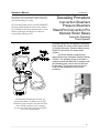
1
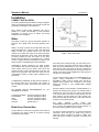
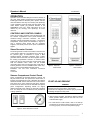
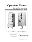
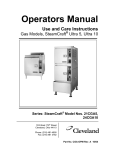
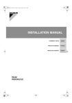
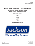
Installation, Operation & Maintenance Manual
CONVECTION STEAMERS
SERIES: 24/36CGM, CEM, CSM, VDM
42CKGM, CKEM, CKSM, CKDM
36CGM16300, 36C3EM1648, 36CSM16, 36CDM16
260-AOZ-A
Operator’s Manual
P/N-260AOZ-A
Table of Contents
INSTALLATION
4
Correct Installation
4
Water Quality
4
Drain Line Connection
4
Installation Safety
5
Installation Instructions
5
Installation checks
6
Gauge Pressure Reading with No Steam Flow* (Static Pressure)
7
OPERATION
8
Controls and Controls Panels
8
Steam Generator Controls
8
Steamer Compartment Control Panels
8
Start-up and Preheat
8
Cooking Operations
9
Cooking Operations for the Key Pad Control Panel
9
Manual Cooking Operation-Key Pad Controls
9
Automatic Cooking Operation-Key Pad Controls
10
Cooking Operations for the Dial Timer Control Panel
10
Manual Cooking Operation-Dial Timer Controls
11
Automatic Cooking Operation-Dial Timer Controls
11
Boiler Shutdown
11
Care and Cleaning
11
Maintenance
12
Preventative Maintenance-Descaling Instructions
13
TROUBLESHOOTING
17
Operators Troubleshooting Guide
17
Troubleshooting Notes
18
CONVECTION STEAMER COOKING INFORMATION
19
CONVECTION STEAMER TIMER SETTINGS
21
______________________________________________________________________________2
Operator’s Manual
P/N-260AOZ-A
Installation
CORRECT INSTALLATION
You have purchased the finest Steam Cooking Equipment
made. The following information we know will increase the
productivity and life span of the equipment.
Every product needs proper installation and with a
steamer it is critical. The following is some important
information you should check on before and during
installation of the equipment.
Water
The quality of water you put into the steam generator is
important. Poor quality water will create generator problems.
Water is no longer just plain and simple water has many
natural ingredients in it. These are called Total Dissolved
Solids, or TDS. This includes calcium, iron, and other
minerals in the water that collect in the steam generator
Because of the droughts in many areas, water and TDS's
are being pumped up from the bottom of the water
systems. If these TDS are not pre-filtered out or cleaned
out with a regular preventive maintenance program, your
steam generator could deteriorate and develop holes.
CHLORIDE is another chemical in our water creating
many problems with all steam generators. When the generator creates steam from the water it also carries the
chloride gas with it. These chlorides begin to eat away the
inside of the generator and follow the steam into the
compartments causing a rusting action (oxidation) as it
goes along.
A CARBON OR CHARCOAL FILTER must be installed on
the incoming water line to the steamer if the chlorine is
over 30 parts per million. These filters will remove the
chloride.
The WATER QUALITY
STEAMER are as follows:
Total Dissolved Solids
Total Alkalinity
Silica
Chloride
pH Factor
REQUIREMENTS
for
your
less than 60 parts per million
less than 20 parts per million
less than 13 parts per million
less than 30 parts per million
greater than 7.5
Drain Line Connection
A proper drain line connection is important. If the drain line
is clogged it can create a back up of pressure causing
extreme and costly repairs.
Figure 1. Drain Connections
If the drain line is not large enough, not open at the end, or
does not have a gravity flow; pressure and hot water will
back up into the compartments. If any of these conditions
exist and hot water does back up into the compartment
someone could be seriously burned and injured. This can
happen even with a correct installation if a drain cleaner is
not used on a regular basis.
An open and free flowing drain line IS REQUIRED for the
proper cooking performance of a CONVECTION
STEAMER. It helps create a swirling action around the
products being cooked. This movement of hot steam
around the product is your CONVECTION STEAM
COOKING.
DO NOT INSTALL UNIT OVER A FLOOR DRAIN. If it
becomes an absolute must, using an 18.' stainless steel or
aluminum pan turn it over and cut a notch in the side wall
to fit over the drain line. Place the pan directly over the
drain opening- DO NOT SEAL TO THE FLOOR. The
steam from the drain line will collect on the under side and
condense into the drain opening.
DO
NOT
INSTALL
GAS
UNITS
ON
FLAMMABLEFLOORS OR NEAR WALLS. A flammable
floor or wall is any material such as wood, linoleum, or
vinyl that is easily ignitable and bums rapidly.
The intent of these instructions is to provide meaningful
information, which will help you obtain many years of
production. Before installing the steamer, please read
those instructions carefully to maintain your safety and
warranty
______________________________________________________________________________
3
Operator’s Manual
INSTALLATION SAFETY
WARNING
Qualified installation personnel, working to all applicable
local and national codes must accomplish installation of
this equipment. Improper installation of this product could
cause or damage.
Do not store or use gasoline or other flammable Vapors
and liquids in the vicinity of this or any other appliance.
The flooring that will be directly under the boiler must also
be made of a noncombustible material.
Cleveland Range equipment is designed and built to comply with applicable standards for manufacturers. Included
among those certification agencies which have approved
the safety of the equipment design and construction:
UL, A.G.A., NSF ASME, CSA, CGA, and others.
Cleveland Range equipment is designed and certified for
safe operation only when permanently installed in accordance with local and I or national codes. Many local codes
exist and it is the responsibility of the owner and installer
to comply with these codes
In no event shall Cleveland Range assume any liability for
consequential damage or injury resulting from installations
which is not in strict compliance with our installation
instructions. Specifically, Cleveland Range will not assume
any liability for damage resulting from improper installation
of equipment including, but not limited to, temporary or
mobile installations
INSTALLATION INSTRUCTIONS
1. These instructions must be retained by the owner/user
for future reference. Gas-fired boilers are only to be installed in noncombustible areas that have provisions for
s
adequate air supply. The term "boiler’ will be used synonymously with "steam generator".
2. Position: For proper operation and drainage, the equipment must be level. It should be placed next to an open
floor drain. DO NOT POSITION THE UNIT DIRECTLY
ABOVE WE FLOOR DRAIN. Observe all clearance requirements to provide air supply for proper operation, as
well as sufficient clearance for servicing. The
surrounding area must be free and clear of
combustibles. Dimensions and clearance specifications
are shown on the specification sheet.
3. Install in accordance with local codes and/or the National
Electric
Code
ANSI/NFPA
No.70-1987.
Installation in Canada must be in accordance with
Canadian Electrical Code CSA Standard C22.1. The
installer A wiring diagram is provided inside the
base cabinet must ground equipment that is
connected to electricity.
P/N-260AOZ-A
WARNING
INJURY TO PERSONNEL AND EQUIPMENT DAMAGE
May result from an improper drain connection. No
connection lines are to be under the unit
4. Drain Line. The drain line outlet discharges exhaust
steam and hot condensate. Connect 1-1/2-inch IPS
piping (or larger) to extend the drain line to a nearby
open floor drain. Up to two elbows and six feet of 11/2-inch IFS (or larger) extension pipe should be
connected to the drain termination. No more than two
pieces of Cleveland Range Equipment should be
connected to one common drain line. The extension
piping must have a gravity flow and vent freely to the
air. This drain outlet must be free-vented to avoid the
creation of backpressure in the steamer cooking
compartments. To ensure a vented drain line, DO NOT
UNDER ANY CIRCUMSTANCES, CONNECT THE
DRAIN OUTLET DIRECTLY TO THE FLOOR DRAIN
OR SEWER LINE. Do not run the drain line discharge
into PVC drain piping or any other drain piping material
not capable of sustaining 180' F operation.
5. Water Supply. Connect COLD water plumbing to the
line strainer (Never conned hot water to the
condensate water fill line strainer) Constant flow
pressure must be maintained between 35 and 60 psi,
and not experience a pressure drop below 35 psi when
other appliances are used. If the water pressure
exceeds 60 psi, a pressure-reducing valve must be
installed in the water supply plumbing to reduce the
water pressure to less than 60 psi. Locations and
pressure data are shown on the specification sheet.
3/S-inch IPS plumbing is sufficient for water supply
lines up to 20 feet in length, but water supply lines
longer than 20 feet should be at least 1/2-inch IPS.
Flush water supply lines thoroughly before connecting
them to the unit. Use water, which is low in total
dissolved solids content and low in gas content to
prevent internal scaling, pitting and corrosion of the
steam generator, and carry-over of minerals into the
steam. Water, which is fit to drink, can still contain
highly detrimental impurities.
NOTE: If equipped with a kettle and kettle water fill swing
spout, 3/8-inch (10 mm) hot and/or coldwater connection(s) will be required at the
swing spout valve.
6. Turn on the cold water supply to the unit Ensure that the
manual water valve, inside the base cabinet is open.
7. Fuel Supply. Connect the primary fuel supply in accordance with the following instructions. Location and other
data are shown on the specification sheet.
______________________________________________________________________________
4
Operator’s Manual
P/N-260AOZ-A
For Gas-Fired Steam Generators: Post in a prominent
location, instructions to be followed in the event the user
smells gas. This information shall be obtained by the
consulting the local gas supplier.
Install a sediment trap (drip leg) in the gas supply line, and
then connect gas supply piping to the boiler gas valve
piping. GAS-FIRED EQUIPMENT IS DESIGNED FOR
INSTALLATION
ONLY
IN
NONCOMBUSJJBLE
LOCATIONS. THIS INCLUDES THE FLOOR-INC THAT
WILL BE DIRECTLY UNDER THE EQUIPMENT Location,
plumbing size, and pressure data are shown on the
specification sheet. Boilers rated at less than 225,000 Btu
require 3/4-inch 'PS gas supply piping, and boilers rated at
225,000 Btu or more require 1-inch II'S gas supply piping.
Natural gas pressure must be between 4" -14" water
column and LP gas supply pressure must be between 12"
- 14" water column. NEVER EXCEED 14" WATER
COLUMN (1/2 psi) GAS PRESSURE. If the gas supply
pressure exceeds 14" water column, a pressure-regulating
valve must be installed in the gas plumbing to reduce the
gas pressure to less than 14" water column. Installation
must be in accordance with local codes, or in the absence
of local codes, with the National Fuel Gas Code, ANSI
Z223.1-1984. Installation in Canada must be in accordance with Installation codes for Gas Burning Appliances and Equipment B149.1 and B149.2. Use a gas pipe
joint compound, which is resistant to LP gas. Turn the gas
valve control knob to ON (the word "on" the knob will be
opposite the index on the valve's body). Test all pipe joints
for leaks with soap and water solutions. Never obstruct the
flow of combustion and ventilation air Observe all
clearance requirements to provide adequate air openings
into the combustion chamber. The appliance and it's individual shutoff valve must be disconnected from the gas
supply piping system during any pressure testing of that
system at test pressures in excess of 14" water column
(1/2 psi or 3.45 k}'a). The appliance must be isolated from
the gas supply piping system at test pressures equal to or
less than 14" water column (1/2 psi or 3.45 kpa). A permanent 115-volt electrical connection is required at the junction box. The junction box location is shown on the specification sheet. The installer must electrically ground the
unit.
and pressure data are shown on the specification sheet.
Incoming steam pressure must be regulated between 35
and 45 psi. A 3 /4inch strainer, equipped with a 20 mesh
stainless steel screen, must be supplied and installed at
the incoming steam connection point. Flush the steam line
thoroughly before connecting it to the boiler. To ensure an
adequate volume of steam, the branch steam supply line
must be 3/~inch 'PS minimum. Connect the inverted
bucket trap to the outlet end of the steam coil. Pill the trap
with water before installing it. A permanent 115-volt
electrical connection is required at the junction box. The
junction box location is shown on the specification sheet.
The installer must electrically ground the unit.
For Electric-Powered Steam Generators: Connect
electric power: location and data are shown on the
specification sheet. Provide connection as required by the
unit, either directly to the single contactor, or to the
terminal block (when equipped with multiple contactors).
Electric supply must match power requirements specified
on the data plate inside the base cabinet. The copper
wiring size must be adequate to carry the required current
at the rated voltage. A separate fused disconnect switch
must be supplied and installed. The installer must
electrically ground the unit
3. Check that the manual water supply valve is open.
For Steam Coil Steam Generators: Connect steam
supply piping to the input side of the steam coil. Location
For Direct-Steam Connected Steamers and Kettles:
Connect steam supply piping to the input side of the line
strainer. Location and pressure data are shown on the
specification sheet. Flush the steam line thoroughly before
connecting it to the steamer. To ensure an adequate
volume of steam, the branch steam supply line must be
3/4 inch 'PSI 'minimum. Direct-steam-connected kettles
require 1 /2-inch 'PS pipe if the kettle total capacity is 20
gallons or less, and 3/4-inch 'PS pipe if the total capacity
exceeds 20 gallons.) A permanent 115 volt electrical
connection is required at the junction box. The junction
box location is shown on the specification sheet. The
installer must electrically ground the unit
INSTALLATION CHECKS
Proper operation of the Cleveland Convection Steamer is
dependent upon proper installation. After the steamer has
been installed, a few quick checks could save
unnecessary service calls.
1. The unit must be level.
2. The Convection Steamer requires a cold water connection for proper efficient operation. DO NOT USE HOT
WATER. The cold water must be connected to the line
strainer, located at the front lower right of the steamer
base.
4. Check all water supply lines and valves for leaks.
5. Check that the water supply pressure and water quality
meets the requirements of installation paragraphs.
6. On electrical units, verify that the supply voltage meets
the voltage requirements on the rating plate inside the
base cabinet and the voltage shown on the packing
slip. Verify that the unit is protected with a separate
fused disconnect and is properly grounded in
accordance with the National Electric Code.
______________________________________________________________________________
5
Operator’s Manual
P/N-260AOZ-A
7. On all gas, steam-coil, and direct steam connected
units, verify that there is a 115-Volt connection at the
handy-box located on the left side of the base.
8. On all steamcoil units, the incoming steam pressure
must be 35-50 psi. Less than 35 will not effectively
operate the unit. Pressure in excess of 50 psi must be
reduced (with a pressure-reducing valve) to 35-50 psi.
9.
Check that the drain lines meet installation
requirements specified in installation paragraph 4
WARNING
INJURY TP PERSONNEL AND EQUIPMENT DAMAGE
may result from an improper installation.
10. After completing checks 1 through 9, correct any
deficiencies refer to the Start-Up and Pre heat
instructions in the Operation section. Verify that the
unit operates properly, make checks 11 and 12.
11.Check to ensure that the water in the boiler sight gauge
glass automatically stays about 1/3 full when boiler is
started up and operated.
12. Check to ensure that the steam pressure gauge
registers 10 psi. The steam pressure is factoryadjusted to 10 psi
Factory setting may shift due to shaking in transit and
resetting will be required after installation. Proper adjustments and maintenance procedures am detailed on a
separate data sheet entitled "Steam Pressure Adjustments." Adjustments should be made only by qualified
service personnel- the factory pressure settings shown in
the accompanying chart should never be exceeded.
GAUGE PRESSURE READING WITH
NO STEAM FLOW* (STATIC PRESSURE)
Self-Contained Steam Generator; Gas or Electric
Operating Pressure Switch
10 psi
High Limit Safety Pressure Switch
15 psi
Self-Contained Steam Coil Generator
Operating Pressure Switch
High Limit Safety Pressure Switch
Steam Supply Pressure Range
10 psi
15 psi
35-45 psi
Direct-Connect (to House Steam Supply)
Steamer Pressure Reducing Valve
10 psi
Steam Supply Pressure Range
15-45 psi
** With or without kettle
______________________________________________________________________________
6
Operator’s Manual
P/N-260AOZ-A
OPERATION
Operation of the Cleveland Range Convection Steamer is
very easy. Each operator should read and understand the
following procedures to effectively start, operate, and shut
down the steamer each day. The owner(s) and operator(s)
of this equipment should be aware that live steam could
cause serious injuries, pay particular attention to the
WARNINGS in this text. These instructions are to be
retained by the owner(s)) and operator(s) for future
reference.
CONTROLS AND CONTROL PANELS
There are two steam generator control arrangements and
two steamer compartment control panels available for
Cleveland Range Convection Steamers. The steam
generator controls are illustrated in Figure 2. The steamer
compartment control panels are illustrated in Figures 3
and 4. Compare these figures with the equipment
supplied, and identify which control panel combinations
applies.
Steam Generator Controls
The steam generator controls are located on the front face
of the steamer base unit. The switches are to the left of
the pressure gage, as illustrated in Figure 2 Most
Cleveland Range Convection Steamers have a steam
generator built into the base unit which supplies steam to
the cooking compartments. However, an external steam
supply may also be used. Units with a built-in boiler have
both the POWER rocker switch and the STEAM
momentary switch next to the pressure gage. Units with no
internal generator have the POWER rocker switch only.
They do not have the STEAM momentary switch.
Installation, Use and Care Instructions Convection
Steamer
Convection
Figure 3. Key Pad
Control Panel
Figure 4. Dial Timer
Control Panel
Steamer Compartment Control Panels
Figure 3 illustrates the standard electronic controls: the
Key Pad Control Panel. This panel has a rocker switch, a
keypad, and a digital timer Figure 4 illustrates the optional
electromechanical controls: the Dial Timer Control Panel.
This panel has a rocker switch and dial timer. Steamer
functions are the same for both the standard and optional
panel configurations. Operating details are slightly
different especially when setting the automatic operating
time. For clarity two sets of instructions are provided for
cooking operations.
START-UP AND PREHEAT
WARNING
Do not attempt to start or operate the Convection
Steamers during a power failure. Critical safety
Circuits are not energized, and serious injury to personnel
or damage to equipment may result.
1. Stan the steam supplies. The steam is either an integral
steam generator boiler) built into the base unit, or an
external steam supply.
• For units without a built-in boiler, refer to the start-up
procedures for the external steam supply and be sure it
is running properly. As soon as the pressure gauge
Figure 2. Steam Generator Controls
______________________________________________________________________________
7
Operator’s Manual
On the Convection Steamer registers 10 psi, steamer
preheating may begin. Skip the remainder of step I, and
begin step 2.
• For units with a built-in boiler, fill the boiler with water
and start the steam generator as described in step a.
through d. below.
a. Press the ON end of the POWER on-off rocker switch
located next to the steam pressure gauge (Figure 2).
The red indicator light in the POWER rocker switch
turns on and the steam generator begins to fill with
water units takes about 5 minutes.
b. When the water level in the steam generator reaches a
safe operating level, the amber light in the STEAM
momentary switch turns on. Whenever the amber light
is on, the heaters, steam supply, or burners are off,
and no steam is being generated. The energy source
(electric, gas, etc.) cannot be activated until the boiler
contains sufficient water, indicated by the amber light.
c. Press the STEAM (amber colored) momentary switch
to produce steam in the boiler this activates the energy
source (electric heaters, gas burners, or steam solenoid valve) and the amber light turns off.
The STEAM switch must be pressed to restart the
steamer after it is shut off for any reason (including a
brief power interruption). No attempt should be made
to operate the equipment during a power failure.
NOTE: For steamers with built-in gas-fired boilers: If the
burners fail to ignite in four seconds, a safety
circuit energizes the system. In this event toggle
the POWER rocker switch to the OFF position
and back to the ON position. The amber light in
the STEAM momentary switch lights. Wait five
minutes, and then press the STEAM momentary
switch to start the burner ignition cycle once
again.
d. About 20 minutes after starting the boiler in step C; the
steam pressure gauge on the unit base should register
10 psi.
2. Preheat
the
Convection
Steamer
cooking
compartments. For accurate, efficient cooking times, the
cooking compartments should be preheated during
startup.
NOTE: With a steamer/kettle combination, if both must
be used at the same time, always heat the kettle
first. When kettle contents begin to simmer,
steam
pressure
returns,
the
steamer
compartments may be preheated
a. Close the compartment door by gently swinging it shut.
P/N-260AOZ-A
b. Refer to timer setting instructions under Automatic
Operation for the appropriate control panel. Set the
Timer for each compartments to one minute, and start
the cooking cycles. Steaming begins in each compartment.
NOTE: On Convection Steamers equipped with
electronic key pad control panels, the timer does
not begin counting down until the cooking
compartment reaches operating temperature.
This may take 2 or 3 minutes if the steamer has
not been operating.
c. Steaming continues for the set one minute. When the
preheating is completed, the steam automatically shuts
off and a 3-second alarm sound. The Convection
Steamer is ready for cooking operations.
COOKING OPERATIONS
The control panels mounted on the cooking compartments
regulate cooking operations. Although cooking operations
are similar for all Convection Steamers, regardless of control panel configuration, separate instructions are provided
for each control panel type.
Cooking Operations for
The Key Pad Control Panel
The electronic keypad control panel illustrated in Figure 3.
The Cleveland Range Convection Steamer has two cooking modes: Manual and automatic. The Manual Mode
provides continuous steaming and is turned on and off by
the MANUAL/TIMED rocker switch. The Automatic Mode
monitors cooking time and compartment temperature to
provide accurate, efficient, uniform steam cooking.
NOTE: Whether using timed or manual cooking modes,
optimum steam heat transfer, and therefore a
higher quality food product, is achieved when
shallow, perforated, uncovered pans are used.
WARNING
STEAM may cause severe burns. Use extreme
Caution when opening the steamer door. Turn face away
from the steamer when first opening the door. Do not look
into the cooking compartment until steam has dewed.
KEEP
HANDS
OUT
OF
THE
COOMNG
COMPARIMENTTO PREVENT BURNS.
Manual Cooking Operation Key Pad Controls
Use manual mode for a continuous supply of steam for
long periods, or if the required cooking time is unknown
and frequent inspection is required.
1.
Place the pan(s) of food into the compartment.
______________________________________________________________________________
8
Operator’s Manual
2. To START the flow of steam, press the MANUAL end of
the MANUAL/TIMED rocker switch, located below the
timer. Steam immediately starts flowing into the
cooking compartment.
3. If inspection is required during steaming, refer to the
LIVE STEAM WARNING. Use extreme caution when
opening the steamer door during steaming operations.
4. Although the timer cannot turn the steam off in manual
mode, it can be used as a conventional cooking timer.
Refer to the timer setting instructions under Automatic
op-era don and set the timer The timer will count down
the set period and sound the buzzer, but WILL NOT
TURN OFF THE STEAM AFTER THE ALARM
SOUNDS.
5. To STOP the flow of steam, press the of the
MANUAL/TIMED rocker switch. Steam stops flowing
into the cooking compartment.
Automatic Cooking Operation Key Pad Controls
Each Convection Steamer cooking compartment is
equipped with an independent electronic digital timer,
which has a maximum setting of 99 minutes and 99 seconds. Each timer is connected to a temperature-sensing
device in the cooking compartment. THE SENSOR Circuit
ALLOWS THE TIMER TO COUNT DOWN ONLY WHEN
THE COOKING COMPARTMENT IS AT THE PROPER
COOKING TEMPERATURE. This assures uniformity in
the cooking times as the timer automatically compensates
for food product defrosting and! Or heat-up time.
1. Place the pan(s) of food into the cooking compartment.
2. Clear and reset the timer. The timer can be set only
when the COOKING ~ME display is clear Press the
CLEAR key on the number pad to zero the timer
3. Set the Desired Cooking Time. The cooking time display contains four digits. The left two digits are minutes, and the right two digits are seconds. The display
12:34 is set for 12 minutes and 34 seconds.
a. To set the cooking time: change the required
cooking time to minutes and seconds, press the
number keys for the minutes, and then press the
number keys for the seconds. If the cooking time
is 99 seconds or less, only press the number keys
for seconds.
b. Example 1. To set the timer for 1 hour and 15
minutes: Change 1 hour (60 min) and 15 minutes
to 75 minutes. Press the following number keys in
sequence: 75 00.The display will read 75:00 when
properly set for 1 hour and 15 minutes.
P/N-260AOZ-A
c. Example 2. To clear the time numbers set in
example 1, press the CLEAR key on the number
pad. The display returns to 00:00.
d. Press the following number keys in sequence: 1 3
0. The display will read 01:30, when set for 1.5
minutes. All seconds method: Change the 1.5
minutes to 90 seconds and press 90. The display
will read 00:90, when set for 1.5 minutes.
4. Press the START/STOP key to start the timer. When
the START/STOP key is pressed, steam enters the
cooking compartment.
a. THE TIMER WILL BEGIN TO COUNT DOWN
ONLY AFTER THE COOKING COMPARTMENT
REACHES PROPER COOKING TEMPERATURE.
The timer automatically delays to compensate for
Defrosting and! Or food product heat-up time.
b. For example, a timer setting of 10 minutes may in
fact take 11 or 12 minutes for the time to count
down and the alarm to sound. This is normal.
Heating the compartment and food to cooking
temperature uses the additional time.
c. To stop or reset the timer, press and hold the
START! STOP key. The cooking time display
returns to the last time setting.
• To restart the same time, press the START/STOP
key.
• To set a new time, press the CLEAR key, and set
the time.
5. When the timer counts down to zero, an alarm
Sounds continuously. Press the START/STOP key to
silence the alarm. The cooking time display returns to
the last time setting. Either run this same setting
again or clear and reset the timer
6. Example 4. To cook two 14 minutes cycles: Press the
CLEAR key to clear the timer Press the following number keys in sequence: The display shows 14:00. Press
the START/STOP)? Key to start the timer. When the
display counts down to zero, the alarm sounds. Press
the START/STOP key, and the display returns to
14:00. Press the START! STOP key to start the second
14-minute cycle.
Cooking Operations for
The Dial Timer Control Panel
The dial timer control panel is illustrated in Figure 4
______________________________________________________________________________
9
Operator’s Manual
The Cleveland Convection Steamer has two cooking
modes: Manual and automatic. The Manual Mode provides continuous steaming and is turned on and off by the
MANUAL/TIMED rocker switch. The Automatic Mode
monitors cooking time to provide accurate, efficient steam
cooking.
NOTE: Whether using timed or manual cooking modes,
optimum steam heat transfer, and therefore a
higher quality food product, is achieved when
shallow perforated, uncovered pans are used.
WARNING
LIVE STEAM may cause severe burns. Use extreme
caution when opening the steamer door Turn face away
from the steamer when opening the steamer door. Turn
face away from the steamer when first opening the door.
Do not look into the cooking compartment until steam has
cleared. KEEP HANDS OUT OF THE COOKING
COMPARTMENT TO PREVENT BURNS.
Manual Cooking Operations Dial Timer Controls
Use Manual mode for a continuous supply of steam for
periods longer than the timer limits (60 minutes), or if the
required cooking time is unknown and frequent inspection
is required.
1. Place the pan(s) of food into the cooking compartment.
2. To START the flow of steam, press the MANUAL end
of the MANUAL I TIMED rocker switch, located below
the timer
3.If food inspection is required during steaming, refer to
the LIVE STEAM WARNING on this page. Use
extreme caution when opening the steamer door
during steaming operations.
4. Although the timer cannot turn the steam off in manual
mode, it can be used as a conventional cooking timer
Refer to the timer setting instructions under Automatic
Operation and set the timer The timer will count down
the set period and sound the buzzer, but IT WILL NOT
TURN OFF THE STEAM AFTER THE ALARM
SOUNDS.
5. To STOP the flow of steam, press the TIMED end of
the MANUAL/~MED rocker switch
P/N-260AOZ-A
Automatic Cooking Operation
Dial Timer Controls
Each Convection Steamer cooking compartment is
equipped with an independent dial timer. This timer controls cooking compartment steaming cycle. Use automatic
mode when an exact cooking time is required. Steam
cooking begins when the timer is set and automatically
stops when the timer counts down the set period.
1. Check that the MANUAL / TIMED rocker switch is in
the TIMED position - If it is not press the ~MED end of
the MANUAL/TIMED rocker switch.
2. Place the pan(s)
compartment.
of
food
into
the
cooking
3. Set the Desired Cooking Time. Turn the dial unit it
points to the desired cooking time. When the dial
timer is set, steam enters the cooking compartment.
4. When the timer counts down to zero, an alarm
sounds for 4 seconds, and steam flow into the
cooking compartment stops.
Boiler Shutdown
The red-lighted power switch must be shut off for 3 minutes a minimum of once every 8 hours to automatically
drain highly mineralized water from the boiler, which reduces the formation of scale. See step J in CARE AND
CLEANING instructions, which follow.
CARE AND CLEANING
The Cleveland Convection Steamer must he cleaned
regularly to maintain its fast, efficient cooking
performance, and to ensure its continued safe, reliable
operation.
1. The boiler must be drained (Blowdown) after a maximum of 8 hours of use. If the boiler feedwater contains
more than 60 parts per million of total dissolved solids,
the boiler must have a Blowdown more often, the frequency depending upon the mineral content of the
feedwater Blowdown means the boiler must be drained
under pressure.
THE BOILER BLOWDOWN IS PERFORMED BY SIMPLY SHUTTING OFF THE STEAMER'S REDLIGHTEDPOWER SWITCH WHILE THE BOILER IS
AT NORMAL 10 PSI OPERATING PRESSURE.
WHEN THEBOTTOM OF THE POWER ROCKER
SWITCH ISPRESSED, ITS RED LIGHT GOES OUT,
AND THE DRAIN VALVE AUTOMATICALLY OPENS,
DRAINING THE BOILER. AUTOMATICALLY TIMED
DRAIN WATER CONDENSER WILL PLUSH THE
DRAIN FOR 3 MINUTES THEN SHUT OFF. AITER 3
MINUTES THE STEAMER IS READY TO BE RESTARTED.
______________________________________________________________________________ 10
Operator’s Manual
P/N-260AOZ-A
When steam is produced, the water in the boiler is
being distilled. During this process, the minerals that
come into the boiler with the water; remain in the
boiler as the water boils away as steam. When
allowed to accumulate, the water becomes highly
mineralized, which results in erratic operation, lime
build-up, corrosion, and premature electric heater
failures. In some cases, complete boiler replacement
becomes necessary, which is extremely expensive.
By draining the boiler under pressure, most sediment
present will be flushed down the drain.
2. The steamer is equipped with a drain in the back of
the cooking compartment. No compartment should
be o~ crated without the drain screen in place. This
screen prevents large food particles from entering
and possibly plugging the drain line. Any restriction
of the drain line may cause a slight build-up of
backpressure in the compartment, resulting in steam
leaks around the door gasket. It also may adversely
affect the convection action of the steam in the
compartment, which is critical to optimum
performance. Pouring USDA approved drain cleaner
through the compartment drains once a week will
help to ensure an open drain. An auger or "snake”
may be safely used to clear obstructions in the
compartment drains. Do not use a power auger, as
damage to the plastic drain system will result.
With the steamer off, open the cooking compartment
doors and allows the steamer to cool before cleaning
the cooking compartments and their components.
3. At the end of each day's operation, wash the pan
slides door gaskets, and compartment interiors with
mild detergent and warm water, either by hand or in
a dishwasher Rinse thoroughly with clear water.
Rinse water should drain freely through the
compartment drain openings. If it does not, the drain
must be cleaned before using the steamer.
4. To prolong door gasket life, always
compartment door ajar when not in use.
leave
5. Exterior Care: Allow steamer to cool before washing.
Use the same cleaners and cleaning procedures as
for other kitchen surfaces of stainless steel and
aluminum. Mild soapy water, with a dear water rinse,
is recommended. DO NOT ALLOW WATER TO
RUN INTO ELECTRICAL Controls. Always turn off
equipment power before using water to wash
equipment. Do not hose down the steamer!
MAINTENANCE
Periodically, a qualified serviceman should be summoned
for routine preventive maintenance.
1. The Blowdown procedure will not completely remove
the mineral deposits that adhere to the top of the boiler. A
boiler treatment specialist should do a chemical descaling.
This should be done 4 times a year in average water
conditions, but in poor water areas it may be needed more
often.
2. A qualified Field serviceman should make periodic
boiler inspections.
3. The cold water line strainer should be cleaned weekly.
Cleveland Range supports a comprehensive network of
Maintenance and Repair Centers (regional parts and service distributors) throughout the United States and
Canada. Please contact your nearest distributor for the
name of an authorized service agency in your area, or for
replacement parts and information regarding the proper
maintenance and repair of Cleveland Range equipment. In
order to maintain the various agency safety certifications,
only factory-supplied replacement pans should be used.
The use of other than factory supplied parts will void the
warranty.
Preventive
Keeping
Maintenance
and
Record
PREVENTIVE MAINTENANCE is the key to keeping your
equipment in top condition. There are certain cleaning
procedures that should be performed on a regular
schedule.
A. DAILY
1. Using a NON-CHLORINE DETERGENT
a. Wipe out the interior of the compartments
b. Wipe the face of the compartments
c. Rinse the pan slides
d. When the steamer is not cooking, leave the door open
resting against the door latch.
e. Wipe down the gaskets to prevent sticking
5. WEEKLY
1. Check the door gasket for wear and reverse or replace
the gasket when needed.
2. Pour a liquid chemical descaler down the back of each
compartment drain.
WARNING
Do not store gasoline or other flammable vapors and
liquids in the vicinity of this or any other appliance.
C. MONTHLY
1. Every 3 to 4 months the generator should be opened
and checked for mineral build up or Chloride corrosion.
______________________________________________________________________________ 11
Operator’s Manual
Look to see if the generator has a buildup of scale greater
than the thickness of a business card or if the top is
beginning to peel off in layers. If either one of these conditions is present, the generator needs to be chemically
descaled by your CLEVELAND AUTHORIZED SERVICE
AGENCY.
a. Inspect more frequently in areas where the water conditions do not meet the Water Quality Requirements.
1. Change the boiler gasket every time you open the
boiler for liability reasons.
2. Check to see that all door fasteners are tight.
3.
P/N-260AOZ-A
authorized service agency to make the REPAIRS
It is in your best interest to maintain as many preventive
maintenance records as possible. When contacted by a
customer or service agency the manufacturer appreciates
having this information available.
The record keeping chart provided with the steam generator would assist you and your service agency. It will
help you record your maintenance and service history of
the equipment.
If you have any questions concerning the proper installation and maintenance of your CLEVELAND STEAM
COOKER call the Cleveland Service Department at (216)
4814900.
Check to see that all steam, water, and electrical connections are secure. If any are loose contact your
______________________________________________________________________________ 12
Operator’s Manual
Descaling is the most important maintenance you
can perform on a steam cooker, and is required by
the Cleveland Range warranty.
The Descaling Pump System circulates DISSOLVE
descaling liquid through the boiler of the steamer.
Recirculating the descaling liquid provides a faster
and more thorough cleaning process than the
conventional soaking process.
P/N-260AOZ-A
Descaling Procedure
Convection Steamers
Pressure Steamers
SteamPro/Convection Pro
Modular Boiler Bases
(Using the Descaling
Pump System)
Cleveland Range has developed the Descaling
Pump System for owners of the Classic Series
Convection Steamers, Pressure Steamers and
SteamPro/Convection Pro series steam
cookers.
The Pump System provides a fast,
highly efficient way to descale Cleveland Steam
Cookers. The descaling Pump Kit includes a
temporary hand-hole plate that is equipped with
two descaling ports, one for the inlet and one
for the outlet. This is to be used only for the
Pump Kit and replaced at the end of the
procedure.
The Descaling Pump System consists of a
submersible pump, a 5-gallon reservoir pail,
Hand-Hole plate with ports, the feed and drain
hoses, and the temporary hose couplings
necessary to connect the system to the Classic
Series Cleveland Steamers.
13
______________________________________________________________________________
Operator’s Manual
P/N-260AOZ-A
NOTE:
Only service technicians authorized by
Cleveland Range should perform the
descaling procedure. Read and
be familiar with the
procedure before starting.
Follow the procedure
exactly as given.
DISSOLVE Descaling Liquid
Use only Cleveland Range DISSOLVE
descaling product. Five gallons of descaling
liquid will be needed during this procedure.
Avoid unnecessary contact with the
descaling product; read and follow safety
precautions on the container label.
Overview of
Pump Descaling Procedures
Below is a summary of the descaling procedure
using the Pump System. The detailed procedure is
given on page 3 and 4.
Descaling should be done as required by your
maintenance schedule. The process takes about an
hour and a half to complete.
Part A – Equipment Setup
•
•
•
•
Turn off the steamer to drain the boiler
Remove the handhold plate of the boiler
and attach the hand-hole plate with the
descaling ports
Connect feed and drain hoses
Fill reservoir pail with DISSOLVE descaling
liquid and insert pump.
Part B – Descaling
•
•
•
•
•
Turn on power to steamer; boiler will begin
to fill
Turn on pump
Monitor liquid levels in boiler and pailregulate level using hand valves
Let liquid circulate for one hour
Turn OFF steamer, pump; boiler will drain
Part C – Clean Water Flush
•
•
•
•
•
DISSOLVE Order Quantities
Container Size
Qty
Part No.
1-gallon bottles
6
106174
5-gallon pail
1
1061741
5-gallon pails
12
10617411
5-gallon pails
24
10617412
•
Turn On steamer; boiler will fill
Empty the pail of spent solution, refill with
fresh water
Route Drain hose to floor drain
Turn pump ON and circulate for 5 minutes,
monitoring water levels
Turn OFF pump; close all valves; turn OFF
steamer; boiler will drain
Replace hand-hole plate, check gasket
Part D –Take Down and Return to Service
•
•
•
Turn ON Steamer; boiler will fill
Remove hoses and couplings;
Activate steam switch; unit ready to operate
14
______________________________________________________________________________
Operator’s Manual
P/N-260AOZ-A
Detail Procedure- Using the Descaling Pump System
A. Equipment Setup
1. Turn the Steamer OFF; the boiler will drain
automatically
2. Open the door at the base of the unit
3. Remove the hand-hole plate and gasket.
Discard old gasket.
4. Inspect the boiler for scale build up.
5. Remove any loose scale within reach that is
around the hand-hole plate.
6. Install Hand-Hole plate with the descaler ports.
And a new gasket.
7. Attach the 3” Feed and Drain nipples with the
attached unions to the INLET and OUTLET
ports.
8. Connect the ½” Feed Hose with attached
union to the bottom of the 3” nipple.
9. Connect the ¾” Drain Hose with the attached
union to the top 3” nipple.
10. Make sure both Feed and Drain Valves are
closed. Drop the open end of the Drain Hose
into the reservoir pail.
11. Fill the reservoir pail with 5 gallons of
DISSOLVE descaling liquid.
12. Lower the Pump into the descaling liquid.
Proceed to Part B, descaling.
Hand-Hole Plate
with Descaler Ports
for Feed and Drain
Hoses. Sight Glass
located on Left.
B. Descaling
1. Turn the Steamer power ON.
2. Turn the Pump ON and open the Feed Hose
Valve to the boiler. Let the boiler fill with
descaler to just above the top of the Sight
Glass before opening the Drain Hose Valve.
Make sure the Drain Line Hose is in the pail
with the pump.
•
Do not allow the
liquid to fall below the pump intake.
Water may be added to reservoir pail to
keep pump intake submerged.
•
Watch for liquid at
the sight glass
3. Open the Drain Hose Valve when the
descaler reaches the level just above the to
of the Sight Glass.
4. While the descaler solution is
circulating, keep an eye on the liquid level in
the pail. Do not allow the level to fall below
the pump intake or to overflow in the pail.
The required level can be maintained by
controlling the flow with the Feed Hose
Valve
5. Let the pump circulate descaler for 1 hour.
6. After 1 hour, turn the Steamer power OFF;
the boiler will automatically drain.
7. Turn OFF the pump; close both the Drain
and Feed Hose Valves. Proceed to Part C,
Flushing.
¾” Drain Hose
and Control
Valve-top
½” Feed Hose
and Control
Valve-bottom
15
______________________________________________________________________________
Operator’s Manual
P/N-260AOZ-A
B. Flushing
1. After the boiler has drained completely, it
must be flushed with water.
2. Turn the Steamer back ON; it will begin to
filling.
3. Remove the Pump from the pail. Remove
the Drain Hose from the pail.
4. Empty the spent descaling solution, refill it
with fresh water and put the pump back in.
5. Do Not put the Drain Hose back in the pail;
instead, route it to a floor drain.
6. While the boiler is refilling, observe the
water level in the sight glass.
7. When the level reaches the middle of the
sight glass, turn ON the pump and open the
Feed Valve of the steamer.
8. When the level reaches the top of the sight
glass, open the Drain Valve of the steamer.
9. Let the pump run 5 minutes; keep an eye on
the water level in the pail; additional water
may be added to keep the pump
submerged.
10. After 5 minutes, turn OFF the pump, close
the Feed and Drain line Valves, turn the
OFF the steamer power; the boiler will
automatically drain. Proceed to Part D.
Takedown and Return to Service
Feed Line
Hose
Drain Line
Hose
D. Takedown and Return to Service
1. The Steamer descaling procedure is
complete; loosen the hose clamps, remove
the hoses.
2. Replace the Hand-hole plate with the
original.
3. Turn the Steamer back ON; the boiler will
refill.
4. When the amber Steam Light comes on,
activate the STEAM switch to bring the unit
back to operating temperature
5. Record the current date in your descaling
maintenance records
16
______________________________________________________________________________
Operator’s Manual
P/N-260AOZ-A
Troubleshooting
OPERATORS TROUBLESHOOTING GUIDE
This troubleshooting guide includes a list of symptoms
that may be encountered during the operation and
maintenance. The first column on the left (problem)
describes these symptoms. The second column lists
possible causes for the problem listed in column one.
The third column lists remedies for the problems and
causes columns one and two. The causes and
remedies are listed in the am
Or they should be checked, with the least costly and
easiest to repair listed first. The third column also
refers to notes that are grouped at the end of the
troubleshooting guide. Refer to these notes when
instructed to do so. Do not try to correct a problem
that requires an authorized service representative as
this may adversely affect warranty coverage.
PROBLEM
POSSIBLE CAUSE
REMEDY/REFERENCE
Switch light does not turn on:
When POWER switch is pressed switch.
On.
Power turned off at main disconnects,
SWITCH
Turn on power at main disconnect switch.
POWER switch light on and
Steam generator does not fill.
Water supply to steamer shut off.
Open water supply valves.
Water line strainer is clogged.
Clean water supply strainer
Water sensors shorted by scale,
Deposits.
Descale steam generator with USDA
Approved descaler.
Inoperative controls or solenoid
See note #1.
No water in steam generator.
See steam generator does not fill (above).
Gas models only
Gas supply valve closed.
Electric models only
Heating elements covered with
Scale.
Turn off steam generator and open gas
supply valve. Refer to Service Manual.
Descale steam generator with USDA
approved descaler
Electric models only
Heating elements damaged.
See note #1.
Water sensors covered by scale
Deposits.
Descale steam generator with USDA
Approved descaler.
Inoperative controls.
See note #1.
hot water instead of cold water
Connected to condenser fitting
Make proper connections. Refer to
Service Manual.
Water supply to condenser turned
off.
Open water supply valve.
Condenser waterline strainer
is clogged.
Clean out condenser water supply line.
See note #1.
Water supply line to the conCondenser blocked, broken, or
leaking.
Repair or replace solenoid. See note #1.
Inoperative condenser solenoid.
Replace solenoid. See note #1.
Inoperative five controls.
Turn off electricity at main disconnect
Switch.
See note #1.
Drain clogged or covered.
Clean drain with USDA approved drain
cleaner.
Door gasket or door parts worn.
See note #1.
Steam Generator does not make
any steam.
Abnormal amount of steam
Coming from drain.
Steam and I or water draining
around compartment door
17
______________________________________________________________________________
Operator’s Manual
PROBLEM
P/N-260AOZ-A
POSSIBLE CAUSE
REMEDY/REFERENCE
Steamer not level
See note #2.
Hot Water to con denser
See note #2.
Steam generator scale buildup.
Descale steam generator with approved
Descaler
Steam nozzle scale buildup.
See note #1.
Steam solenoids scale buildup
See note #1.
Electric models only
Voltage too low for unit.
See note #4.
Electric models only
Faulty heating element or controls.
See note #1.
Operating in manual mode.
Switch to timed mode for timer to be
Effective.
Stuck open steam valve
See note #1.
Inoperative five controls inside
Cabinet.
Turn off electricity at main disconnect
switch. See note #1.
Water leaking from bottom of
Cabinet.
broken or loose plumbing inside
steamer cabinet.
Turn off electricity at main disconnects
switch and close water supply valve(s).
See note #1.
Water leaking from water pipes
or drain lines.
Plumbing needs repair
See note #3.
Food takes too long to cook.
(Cook in perforated pans when
possible.)
Not enough steam movement in
compartment. Hot water conConnected to condenser line.
Make proper connections. Refer to Service
Manual.
Pans too close to the bottom of
cabinet.
Put pans in racks near top of cabinet.
Steam generator scale buildup.
approved descaler
Descale steam generator with USDA
Compartment overloaded with
too much food.
Put less food in pan. Use fewer pans.
Voltage too low for unit.
See note #4.
Suggested cooking times are
usually listed for cooking at sea Level
Extend cooking times for altitudes above
2500 FEET.
Juices and /or food leaking from
pans.
Put a solid pan under perforated pans to
catch drippings, or put less food in pan.
Reduced steam flow into cooking
Compartment.
Steam flow does not stop when
timer stops.
Compartment bottom dirty with
food drippings.
TROUBLESHOOTING NOTES
1. If problem is inside the steamer, call an authorized
Service representative Cleveland Range will not pay for
Non- warranty repair centers.
2. Proper installation of the Convection Steamer
Responsibility of the owner or installer Refer to Cleveland
3. Repair to external wiring should be done by a Licensed
Electrician.
4. For more information on products and services, contact
your nearest Authorized Service Representative.
18
______________________________________________________________________________
Operator’s Manual
CONVECTION STEAMER
Cooking Guidelines
Introduction:
Steam Cooking is an excellent way to prepare
countless foods. With large and small quantities you will
find cooking to be efficient, economical, fast and
convenient. Food can never burn-pans will never boil
over-there is no heavy lifting of water in pots-no
scouring of containers-no waiting for boiling to start.
Steam cooking is efficient, economical and convenient.
From the Steamer to the steam table, it saves money in
labor/time, and, of course, the quality and consistently
remains the same.
Seafood:
Steaming seafood is an excellent method of cooking a
variety of seafood. From the freezer directly into the
steamer gives you, the operator, portion control on
P/N-260AOZ-A
expensive seafood products. Steamed fish is tender,
succulent, and flaky and table ready in a matter of
minutes.
Vegetables:
Steam cooking vegetables, either fresh or frozen,
enhances color, improves flavor, and helps retain
vitamins when recommended timer settings are
followed. Steaming fresh vegetables on perforated pans
gives best results.
Meat:
Steam provides an even, intense and penetrating heat,
which, because of its nature, cooks meat with minimal
shrinkage. The meat is tender, moist and flavorful.
Stews, pot roasts, ham and corned beef are excellent
steam cooked. Steam tenderizes stewing fowl. It
produces excellent meat for sandwiches and salads,
both moist and savory and is easily sliced.
Desserts:
Many kinds of cornstarch pudding and custard desserts
are prepared by steaming. Fruit desserts such as
steamed “Baked Apples” are another suggestion. Core
the apple and arrange on a shallow pan. Fill the cored
apple with cinnamon and sugar, then steam. If desired,
browning under the broiler may finish the apples.
Applesauce is another steam application, as are stewed
pears or peaches. Dried fruit, properly marinated, turn
out
beautifully.
Additional Ideas:
There are many applications for steam cooking besides vegetables and seafood:
•
Eggs can be soft cooked, coddled, hard cooked, poached, scrambled, and made into custard or pudding. 25 dozen
eggs can be hard cooked in 12 minutes using three 12” x 20”” x 2½” perforated pans in one compartment of the
steamer.
•
Momentary steam blanching of fruits, including citrus and pineapple, simplifies skin removal.
•
Dumplings, steamed breads, muffins, hot cereal, pasta, noodle and rice can be prepared or reheated in the steamer.
•
Beef and other meat, cooked by steaming, is moist, tender and flavorful. The meat drippings from the catch pan can
be used to make gravy soups or clear stock, as a salt free broth.
•
Turkey, chicken and other poultry are tender, juicy when steamed then combined into a casserole, added to BBQ
sauce, or browned under the broiler. Chicken pieces can be breaded, steamed, then finished in the deep fryer. It is
crisp, delicious, and juicy.
•
Hot Dogs, sausages and other variety meats remain plump and juicy when steamed.
•
Entrees such as lasagna, macaroni and cheese, or beef stew can be prepared from scratch. Frozen institutional
packs can be reheated in the steamer. It is not necessary to cover.
19
______________________________________________________________________________
Operator’s Manual
P/N-260AOZ-A
Sizing Up Pan Capacity: How Much? How Many?
How to estimate portion size and number of servings from a standard steam table pan.
•
A 12” x 20” x 2½” (65mm-1/1GN) solid pan will hold 1-7/8 gallons or
240 fluid ounces (30 liters or 7200ml)
Portion Size
10 oz (300ml)
8 oz (240ml)
6 oz (180ml)
4 oz (120ml)
2 oz (60ml)
1 oz (30ml)
•
240 Fluid Ounces Produces (7200ml)
Number of Servings
24
30
40
60
120
240
Type of Product
Stew, Casserole, Lasagna
Soup, Bisque
Soup, Bisque
Mashed Potatoes
Sauce
Number of servings of cooked vegetables from one 12” x 20” x 2½” perforated pan.
(65mm-1/1GN)
Frozen Vegetables Yields:
10.0 lbs. (4.5kgs)
Approx. 50-3 oz (90ml) servings
7.5 lbs. (3.4kgs)
Approx. 30-3 oz (90ml) servings
5.0 lbs.
Approx. 25-3 oz (90ml) servings
For Units with Mechanical Timers:
Cleveland’s Electronic Controls
With Compensating Thermostat:
•
•
•
•
•
•
Durable and Reliable
Simple and Easy to Operate
Automatically adjusts the cooking time for the
volume of product steamed
Manual Bypass Switch for Constant Steam
Audible Signal for cooking time completion
Automatically resets to the original time after
cycle is completed
Consistent-Worry Free Cooking Results!
20
______________________________________________________________________________
Operator’s Manual
P/N-260AOZ-A
Convection Steamer Suggested Timer Setting Guidelines
Electronic Controls with the Compensating Thermostat
Timer settings are approximate due to the differences in food quality, age, shape and the degree of doneness desired. It
is not necessary to add water. Perforated pans are recommended. Starred items (*) must be cooked in solid pans. Items
marked with two stars (**) require handling in two steps. First steam for approximately ½ the time shown, remove from
steamer, separate thawed portion, or stir, and return to steamer for the time remaining. The compensating feature of the
timer allows the cooking compartment to reach temperature before the preset time starts to count down.
VEGETABLES:
Fresh
Artichoke
12
Asparagus, spears
4
Beans, green, 2” cut
6
French cut
4
Whole
6
Broccoli, spears
3
Flowerets
2-3
Chopped
Brussels sprouts
4-5
Cabbage,
2
Whole to remove
Leaves for cabbage rolls
Carrots-baby whole
10
Sliced,
7-8
Diced
Cauliflower,
Flowerets
4-5
Whole
10
Celery, Dai. Cut 1½”
3
Diced
2
Minced
1
Corn, yellow, whole
On cob, 6
Cobbettes
6
Eggplant, sliced,
1
Mixed Vegetables
Mushrooms,
Whole 1½”
3
Sliced
1
Onions, diced, sliced
2-3
Whole
4
Peas, green
Potatoes, whole 8 oz.
30-35
Peeled, quartered,
12-19
Fresh peeled, diced
8-10
Potatoes, sweet,
30-35
Whole
Spinach leaf
2
Chopped
Squash, acorn halves
Butternut, quartered
Squash whipped*
Spaghetti squash, halves 15-18
Tomatoes, whole, sliced* 1
Turnips, whole
20-25
Zucchini, sliced
2-4
Fresh
Frozen
6
5
5**
4
2-3
1-2
6-8
4
6
3
2
3-4
1
2
12**
12**
3-4
1
2
2
21**
21**
20**
2-4
Frozen
SEAFOODS: Steam all seafood on a perforated pan with
catch pan
Clams in shell
3-5
Cod fillets, 5 oz.
3
4
Portions
Crab legs, king
4-6
Snow crab
2-4
Crab, live, 4 oz.
3/4 - 1 lb.
12
Halibut, 6-8 oz.
4-6
6-8
Portions
Lobster, whole, 1 lb.
7-9
Lobster tails, 8 oz.
8-10
Defrosted, butterflied
4-6
Mussels in shell
2
Oysters in shell
2-4
Red snapper, 8 oz.
4-5
4-5
Salmon steak, 8 oz.
6
7
Shrimp, 10 ct. per lb. IQF
3
4-6
5lb. Block, peeled &
6-8
Deveined 30 ct.
5lb. Block, green, (nested pan) 26-30 ct.
10**
EGGS (Medium Sized):
Hard cooked for egg
Salad, potato salad
Soft cooked
Coddled
Poached in a cup
Scrambled*
FRUITS:
Blanch for peeling
Fresh: Avacado
Apple, cored
Grapefruit
Orange
Apricot
Pineapple, whole
Dried: add water to re-hydrate
Apple
Apricot
Peach
Pear
Prune
10-12
3
6
2-3
6-7**
1
1
1
1
1
2
10
10
10
10
10
21
______________________________________________________________________________
Operator’s Manual
P/N-260AOZ-A
MEATS & POULTRY:
Meats and poultry in nested pans, as juices can be used
for gravy, sauces, beef stock and soups. The portion size,
thickness, grades, should be considered when selecting a
timer setting for doneness.
POULTRY:
Fresh
Turkey, whole
6-8 min./lb.
Chicken, 5-8 oz.
Breaded piece 18-20 min.
halves, 1 1/4-1 1/2
lb. per half
20-24 min.
6 min./lb.
4-6 min./lb.
2-4 min./lb.
STEAKS:
Using a 3/4” to 1” steak, the steaming time listed below
produces a “rare” steak. A “well done” steak is first
steamed to the “rare” stage, then broiled or grilled for 1 1/2
minutes on each side. This “well done” steak shrinks less,
is more tender and juicy; and, when served, is the same
size as the “rare” steak.
Sirloin Patties
Chopped 8 oz
Ribeye, 8 oz.
Top butt steak
6 oz.
8 oz.
Filet Mignon, butterflied –
4 oz.
4 min.
4 min.
4 min
6 min.
3 min.
3-4 min.
4 min.
5 min.
8.min
Strip steak -
10-oz.
12 oz.
5 min.
7 min.
T-bone
12 oz.
16 oz.
18 oz.
22 oz.
5 min.
8 min.
8 min.
10 min.
Frozen
6-8 min./lb.
PORK, SAUSAGE, HOT DOGS:
Pork, Chop, 4 count/lb.
10 min.
Italian sausage, 4 oz.
10 min.
Ribs, 3lb. and down
20-26 min.
Hot-dogs, 8 count/lb.
2 min.
BEEF:
Cubes, 1 1/2”
6-7 min./lb.
Ground chuck for chili
4 min./lb.
Pot-roast, choice 8-12 min./lb.
Rump roast, choice
Boned, rolled, tied
12 min./lb.
Meat loaf, 4lb. Loaf
5 min./lb.
Liver, baby beef, 8oz.
2-4 min./lb.
Corned beef, 6-8lb.
cut, add 1/2” water
Pan
20-23 min./lb.
6 oz.
8 oz.
10 oz.
16 oz.
(Chateaubriand)
PREPARED ENTREES:
Full Size Pans
Cabbage rolls, stuffed*
Cover with tomato
Sauce & serve
Casserole dishes*
Beef Stew
Stroganoff
Lasagna* fresh
Reheat ea. serving 4”
Fresh
Frozen
25 min.
20 min.
20-25 min
20-25 min.
20-25 min
6-8 min.
25-30 min.
25-30 min.
25-30 min.
12 min.
DEHYDRATED FOODS:
Potatoes* 2 ½” random sliced
Plus 5 cups cold water /lb.
RICE & BEANS:
Rice, long grain
4 cups cold water/lb.
Beans, pre-soaked overnight,
1 lb. Beans = 1 ¼ qt. Water
Beans* unsoaked,
1 lb. Beans x 1 ½ qt. water
Refried beans, 2-#10 cans
12 min.
17 min.
45 min.
2 ½ Hours
15-17 min.
PASTA:
Steam in nested pans. Place pasta on 2 ½” perforated pan
used as a liner in a solid 2 ½” pan. Cover pasta with cold
water.
Egg noodles, 1 ½” wide
4-6 min. **
Lasagna noodles
10-12 min.**
Macaroni, shells, elbow
10-12 min.**
Rigatoni
10 min. **
Spaghetti, vermicelli
8 min.**
Spaghetti, regular
8 min.**
22
______________________________________________________________________________
Operator’s Manual
P/N-260AOZ-A
NOTES:
23
______________________________________________________________________________