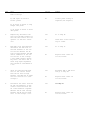
1
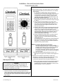
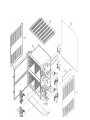
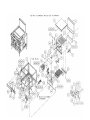
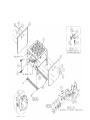
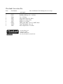
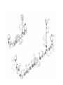
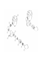
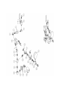
Cleveland Range
REPAIR
MANUAL
Model No.
36CEM1648
36CGM16300
36CDM16
36CSM16
Cleveland Range, Inc.
UNITED STATES
1333 East 179th St.
Cleveland, Ohio 44110
Phone: (216) 481-4900 • Telex: 98-0546 • FAX: (216) 481-3782
CANADA
Garland Commercial Ranges • 1177 Kamato Rd.
Mississauga, Ontario CN L4W 1X4
Phone: (416) 624-0260 • FAX: (416) 624-0623
FSC-04
Installation, Use and Care Instructions
Convection Pro XVI
INSTALLATION
nected to electricity must be grounded by the installer. A wiring
diagram is provided inside the base cabinet.
INSTALLATION SAFETY
WARNING
Installation of this equipment must be accomplished by
qualified installation personnel, working to all applicable local
and national codes. Improper installation of this product could
cause injury or damage.
DO NOT store or use gasoline or other flammable vapors and
liquids in the vicinity of this or any other appliance.
The flooring that will be directly under the boiler must also be
made of a noncombustible material.
Cleveland Range equipment is designed and built to comply
with applicable standards for manufacturers. Included among
those certification agencies which have approved the safely of
the equipment design and construction are: UL, A.G.A., NSF,
ASME, CSA, CGA, and others.
Cleveland Range equipment is designed and certified for safe
operation only when permanently installed in accordance with
local and/or national codes. Many local codes exist and it is the
responsibility of the owner and installer to comply with these
codes.
In no event shall Cleveland Range assume any liability for
consequential damage or injury resulting from installations
which are not in strict compliance with our installation instructions. Specifically, Cleveland Range will not assume any
liability for damage or injury resulting from improper installation of equipment, including, but not limited to, temporary or
mobile installations.
INSTALLATION INSTRUCTIONS
1. These instructions must be retained by the owner/user for
future reference. Gas-fired boilers are only to be installed in
noncombustible areas that have provisions for adequate air
supply. The term "boiler" will be used synonymously with
"steam generator".
2. Position: For proper operation and drainage, the equipment
must be level. It should be placed next to an open floor drain.
DO NOT POSITION THE UNIT DIRECTLY ABOVE THE
FLOOR DRAIN. Observe all clearance requirements to
provide air supply for proper operation, as well as sufficient
clearance for servicing. The surrounding area must be free
and clear of combustibles. Dimensions and clearance
specifications are shown on the specification sheet.
3. Install in accordance with local codes and/or the National
Electric Code ANSI/NFPA No. 70-1987. Installation in
Canada must be in accordance with the Canadian Electrical
Code CSA Standard C22.1. Equipment that is con-
Printed 6/90
WARNING
INJURY TO PERSONNEL AND EQUIPMENT DAMAGE may
result from an improper drain connection.
4. The drain line outlet discharges exhaust steam and hot
condensate. Connect 1-1/2-inch IPS piping (or larger) 10
extend the drain line to a nearby open floor drain. Up 10 two
elbows and six feet of 1-172-inch IPS (or larger) extension
pipe should be connected to the drain termination. Drain
piping extended six to twelve feet, or using three elbows,
should be increased to 2 -inch IPS No more than two pieces of
Cleveland Range equipment should be connected to one
common drain line. The maximum length of extension from
the drain termination should not exceed six feet and use no
more than TWO elbows - The extension piping must have a
gravity flow and vent freely to the air. This drain outlet must be
free-vented to avoid the creation of back pressure in the
steamer cooking compartments. To ensure a vented drain
line, DO NOT, UNDER ANY CIRCUMSTANCES, CONNECT
THE DRAIN OUTLET DIRECTLY TO THE FLOOR DRAIN
OR SEWER LINE. Do not run the drain line discharge into
PVC drain piping or any other drain piping material not
capable of sustaining 180°F operationNOTE: Direct-steam connected pressure steamers do not require
a cold water connection, and therefore steps 5 and 6 do
not apply. Refer directly to step 7. A kettle fill faucet, if
so equipped, requires a hot and/or cold water
connection The data contained in step 5 for
cold water also applies to hot water.
5. Connect COLD water supply plumbing to the line strainer.
(Never connect hot water to the boiler water fill line strainer.)
Constant flow pressure must be maintained between 35 and
60 psi, and not experience a pressure drop below 35 psi when
other appliances are used. If the water pressure exceeds 60
psi, a pressure reducing valve must be installed in the water
supply plumbing to reduce the water pressure to less than 60
psi- Locations and pressure data are shown on the
specification sheet. 1/4-inch IPS plumb ing is sufficient for
water supply lines up to 20 feet in length, but water supply
lines longer than 20 feet should beat least 3/8-inch IPS. Flush
water supply lines thoroughly before connecting them to the
unit. Use water which is low in total dissolved solids content
and low in gas content to prevent internal scaling, pitting and
corrosion of the steam generator, and carry-over of minerals
into the steam. Water which is fit to drink can still contain
highly detrimental impurities.
NOTE: If equipped with a kettle and kettle water fill swing
spout, 3/8-inch (10mm) hot and/or cold water connections) will be required at the swing spout valve.
6. Turn on the cold water supply to the unit. Ensure that the
manual water valve, inside the base cabinet, is open.
Cleveland Range, Inc.
Installation, Use and Care Instructions
Convection Pro XVI
Connect the primary fuel supply in accordance with the
following instructions. Location and other data are shown on
the specification sheet.
For Gas-Fired Steam Generators: Post in a prominent
location, instructions to be followed in the event the user
smells gas. This information shall be obtained by consulting
the local gas supplier. Install a sediment trap (drip leg) in the
gas supply line, then connect gas supply piping to the boiler
gas valve piping. GAS-FIRED EQUIPMENT IS
DESIGNED FOR INSTALLATION ONLY IN NONCOMBUSTIBLE LOCATIONS. THIS INCLUDES THE
FLOORING THAT WILL BE DIRECTLY UNDER THE
EQUIPMENT. Location, plumbing size, and pressure data
are shown on the specification sheet. Boilers rated at less that
225,000 BTU require 3/4-inch IPS gas supply piping, and
boilers rated at 225,000 BTU or more require 1-inch IPS gas
supply piping. Natural gas pressure must be between 4" -14"
water column, and L.P. gas supply pressure must be between
12" - 14" water column. NEVER EXCEED 14" WATER
COLUMN (1/2 psi) GAS PRESSURE. If the gas supply
pressure exceeds 14" water column, a pressure regulating
valve must be installed in the gas supply plumbing to reduce
the gas pressure 10 less that 14" water column. Installation
must be in accordance with local codes, or in the absence of
local codes, with the National Fuel Gas Code, ANSI 7.773.11984. Installation in Canada must be in accordance with
Installation codes for Gas Burning Appliances and Equipment B149.1 and B149.2 Use a gas pipe joint compound
which is resistant to LP gas. Turn the gas valve control knob
to ON (the word "on" on the knob will be opposite the index
on the valve's body). Test all pipe joints for leaks with soap
and water solution. Never obstruct the flow of combustion
and ventilation air. Observe all clearance requirements to
provide adequate air openings into the combustion chamber.
The appliance and its individual shut-off valve must be
disconnected from the gas supply piping system during any
pressure testing of that system at test pressures in excess of
14" water column (1/2 psi or 3.45 kPa). The appliance must
be isolated from the gas supply piping system at test
pressures equal to or less than 14" water column (1/2 psi or
3.45 kPa). A permanent 115 volt electrical connection is
required at the junction box. The junction box location is
shown on the specification sheet. The unit must be
electrically grounded by the installer.
For Electric-Powered Steam Generators: Connect electric
power: location and data are shown on the specification
sheet. Provide connection as required by the unit; either
directly to the single contactor, or to the terminal block
(when equipped with multiple contactors). Electric supply
must match power requirements specified on the data plate
inside the base cabinet. The copper wiring must be adequate
to carry the required current at the rated voltage. A separate
fused disconnect switch must be supplied and installed. The
unit must be electrically grounded by the installer.
Cleveland Range, Inc.
For Steam Coil Steam Generators: Conned steam supply
piping to the input side of the steam coil Location and pressure
data are shown on the specification sheet. Incoming steam
pressure must be regulated between 35 and 45 psi. A 3/4-inch
strainer, equipped with a 20 mesh stainless steel screen, must
be supplied and installed at the incoming steam connection
point. Flush the steam line thoroughly before connecting it to
the boiler. To ensure an adequate volume of steam, the branch
steam supply line must be 3/4-inch IPS minimum. Connect the
inverted bucket trap to the outlet end of the steam coil. Fill the
trap with water before installing it. A permanent 115 volt
electrical connection is required at the junction box. The
junction box location is shown on the specification sheet. The
unit must be electrically grounded by the installer.
For Direct-Steam Connected Steamers/Kettles: Connect
steam supply piping to the input side of the line strainer.
Location and pressure data are shown on the specification
sheet. Flush the steam line thoroughly before connecting it to
the steamer. To ensure an adequate volume of steam, the
branch steam supply line must be 3/4-inch IPS minimum.
(Direct-steam-connected kettles require 1/2-inch IPS pipe if
the kettle total capacity is 20 gallons or less, and 3/4-inch IPS
pipe if the total capacity exceeds 20 gallons.) A permanent
115 volt electrical connection is required at the junction box.
The junction box location is shown on the specification sheet.
The unit must be electrically grounded by the installer.
Installation Checks
Proper operation of the Cleveland Convection Pro XVI steamer is
dependent upon proper installation. After the steamer has been
installed, a few quick checks could save unnecessary service
calls.
1. The unit must be level
2. The Convection Pro XVI steamer requires a cold water
connection for proper, efficient operation. DO NOT USE HOT
WATER. The cold water must be connected to the line strainer,
located at the front lower-right of the steamer base.
3. Check that the manual water supply valve is open.
4. Check all water supply lines and valves for leaks.
5. Check that the water supply pressure and water quality
meet the requirements of installation paragraph 5.
6. On electric units, verify that the supply voltage meets the
voltage requirements on the rating plate inside the base
cabinet, and the voltage shown on the packing slip. Verify
that the unit is protected with a separate fused disconnect, and
is properly grounded in accordance with the National Electric
Code.
7. On gas, steam coil, and direct-steam-connected units, verify
that there is a 115 Volt connection at the handi-box located on
the left side of the base at the bottom front.
Printed 6/90
Installation, Use and Care Instructions
Convection Pro XVI
8. On steam coil units, the incoming steam pressure must be 35 to 50 psi
Less than 35 psi will not effectively operate the unit. Pressure in
excess of 50 psi must be reduced (with a pressure reducing valve) to
35 to 50 psi
WARNING
INJURY TO PERSONNEL AND EQUIPMENT DAMAGE may
result from an improper drain connection.
OPERATION
Operation of the Cleveland Range Convection Pro XVI steamer is very
easy. Each operator should read and understand the following
procedures to effectively start, operate, and shut down the steamer each
day. The owner(s) and operator(s) of this equipment should be aware
that live steam can cause serious injuries, and pay particular attention to
the WARNINGS in this text. These instructions are to be retained by
the owner(s) and operator(s) for future reference.
Controls and Control Panels
9. Check that the drain lines meet the installation requirements
specified in installation paragraph 4.
lO. After completing checks 1 through 9, and correcting any
deficiencies, refer to the Start-up and Preheat instructions in
the Operation section. Verify that the unit operates property,
and make checks 11 and 12.
11. Check to ensure that the water in the boiler sight gage glass
automatically stays about 1/3 full when the boiler is started
up and operated.
12. Check 10 ensure that the steam pressure gage registers 10
psi.
The steam pressure is factory-adjusted 10 provide the proper
pressure. In some cases, however, the factory setting may
shift due to shaking in transit, and resetting will be required
after installation. Proper adjustments and maintenance
procedures are detailed on separate data sheet entitled
"Steam Pressure Adjustments." Adjustments should be made
only by qualified service personnel. The factory pressure
settings shown in the accompanying chart should never be
exceeded.
Gage Pressure Reading with No Steam Flow*
(Static Pressure)
Self-Contained Steam Generator, Gas or Electric
Operating Pressure Switch
10 psi
High Limit Safety Pressure Switch
psi
15
There are two steam generator control arrangements and two
steamer compartment control panels available for Cleveland
Range Convection Pro XVI steamers. The steam generator
controls are illustrated in Figure 1. The steamer compartment
control panels are illustrated in Figures 2 and 3. Compare these
figures with the equipment supplied, and identify which control
and panel combinations apply.
Steam Generator Controls
The steam generator controls are located on the front face of the
steamer base unit. The switches are to the left of the pressure
gage, as illustrated in Figure 1. Most Cleveland Range
Convection Pro XVI steamers have a steam generator built into
the base unit which supplies steam to the cooking compartments.
However, an external steam supply may also be used. Units with
a built-in boiler have both the POWER rocker switch and the
STEAM momentary switch next 10 the pressure gage. Units with
an external steam supply have the POWER rocker switch only.
They do not have the STEAM momentary switch.
Steamer Compartment Control Panels
Figure 2 illustrates the standard electronic controls: the Key Pad
Control Panel. This panel has a rocker switch, a key pad, and a
digital timer. Figure 3 illustrates the optional electromechanical
controls: the Dial Timer Control Panel. This panel has a rocker
switch and dial timer. Steamer functions are the same for both
the standard and optional panel configurations. Operating details
are slightly different especially when setting the automatic
operating time. For clarity, two sets of instructions are provided
for cooking operations.
Setf-Contained Steam Coil Generator
Operating Pressure Switch
10 psi
High Limit Safety Pressure Switch
15 psi
Steam Supply Pressure Range
35-45
psi
Direct-Connect (to House Steam Supply)
Steamer Pressure Reducing Valve
Steam Supply Pressure Range
10 psi
15-45 psi
*with or without kettle
Printed 6/90
Cleveland Range, Inc.
Installation, Use and Care Instructions
Convection Pro XVI
2. Start the steam supply. The steam supply is either an integral
steam generator (boiler) built into the base unit, an external
steam supply.
• For units without a built-in boiler, refer to the start-up
procedures for the external steam supply and be sure i t is
running properly- As soon as the pressure gage on the
Convection Pro XVI Steamer registers 10 psi, steamer
preheating may begin. Skip the remainder of step 2, and
begin step 3, preheat instructions.
• For units with a built-in boiler, fill the boiler with water and
start the steam generator as described in steps a.through
d. below.
a. Press the ON end of the POWER on-off rocker switch
located next to the steam pressure gage (Figure 1). The
red indicator light in the POWER rocker switch turns on
and the steam generator begins to fill with water. This
takes about 5 minutes.
b. When the water level in the steam generator reaches a safe
operating level, the amber light in the STEAM momentary
switch turns on. Whenever the amber light is on, the
heaters, steam supply, or burners are off, and no steam is
being generated. The energy source (electric, gas, etc.)
cannot be activated until the boiler contains sufficient
water, indicated by the amber light.
c. Press the STEAM momentary switch to produce steam in
the boiler. This activates the energy source (electric
heaters, gas burners, or steam solenoid valve) and the
amber light turns off.
The STEAM switch must be pressed to re-start the steamer
after it is shut off for any reason (including a brief power
interruption.). No attempt should be made 10 operate the
equipment during a power failure.
NOTE: For steamers with built-in gas -fired boilers:
If the burners fail to ignite in four seconds, a safety
circuit de-energizes the system. In this event, toggle the
POWER rocker switch to the OFF position and back to
the ON position. The amber light in the STEAM
momentary switch lights. Wait five minutes, then press
the STEAM momentary switch to start the burner ignition
cycle once again.
d. About 20 minutes after starting the boiler in step c, the
steam pressure gage on the unit base should register 10
PSI.
3. Preheat the Convection Pro XVI steamer cooking com partments. For accurate, efficient cooking times, the cooking
compartments should be preheated during startup.
Start-up and Preheat
WARNING
Do not attempt to start or operate the Convection Pro
XVI steamer during a power failure. Critical safety circuits are not energized, and serious injury to personnel
or damage to equipment may result.
a. Close the compartment door by gently swinging it shut.
b. Refer to timer setting instructions under Automatic Operation
for the appropriate control panel. Set the timer for each
compartment 10 one minute , and start the cooking cycles.
Steaming begins in each compartment.
1. Inspect the steamer. Check the cooking compartments 10
ensure that the steam tubes and drain screens are in place and
secure. Check inside the steamer base cabinet to ensure that
the manual drain valve is closed and the manual water supply
valve is open.
Cleveland Range, Inc.
Printed 6/90
Installation, Use and Care Instructions
Convection Pro XVI
NOTE: On Convection Pro XVI steamers equipped with the electronic
key pad control panels, the timer does not begin counting
down until the cooking compartment reaches operating
temperature. This may take 2 or 3 minutes if the steamer has
not been operatingc. Steaming continues for the set one minute. When the preheating
is completed, the steam automatically shuts off and a 3-second
alarm sounds. The Convection Pro XVI steamer is ready for
cooking operations.
COOKING OPERATIONS
The control panels mounted on the cooking compartments
regulate cooking operations. Although cooking operations are
similar for all Convection Pro Steamers, regardless of control
panel configuration, separate instructions are provided for each
control panel type.
Cooking Operations for The Key
Pad Control Panel
The electronic key pad control panel is illustrated in Figure
2.
The Cleveland Range Convection Pro XVI steamer has two
cooking modes: Manual and Automatic. The Manual Mode
provides continuous steaming and is turned on and off by the
MANUAL/TIMED rocker switch- The Automatic Mode
monitors cooking time and compartment temperature to provide
accurate, efficient, uniform steam cooking.
NOTE: Whether using timed or manual cooking modes,
optimum steam heat transfer, and therefore a higher
quality food product, is achieved when shallow, perforated, uncovered pans are used.
WARNING
LIVE STEAM may cause severe bums. Use extreme caution
when opening the steamer door. Turn face away from the
steamer when first opening the door. Do not look into the
cooking compartment until steam has cleared. KEEP HANDS
OUT OF THE COOKING COMPARTMENT TO PREVENT
BURNS.
Manual Cooking Operation - Key Pad Controls
Use manual mode for a continuous supply of steam for long
periods, or if the required cooking time is unknown and
frequent inspection is required.
1. Place the pan(s) of food into the cooking companment2. To START the flow of steam, press the MANUAL end of the
MANUAL/TIMED rocker switch, located below the timer.
Steam immediately starts flowing into the cooking
compartment
3. If food inspection is required during steaming, refer to the
LIVE STEAM WARNING above. Use extreme caution
when opening the steamer door during steaming operations.
Printed 6/90
4. Although the timer can not rum the steam off in manual
mode, it can be used as a conventional cooking timer. Refer
to the timer setting instructions under Automatic Operation
and set the timer. The timer will count down the set period
and sound the buzzer, but IT WILL NOT TURN OFF THE
STEAM AFTER THE ALARM SOUNDS.
5. To STOP the flow of steam, press the TIMED end of the
MANUAL/TIMED rocker switch. Steam stops flowing into
the cooking compartment.
Automatic Cooking Operation - Key Pad Controls
Each Convection Pro XVI steamer cooking compartment is
equipped with an independent electronic digital timer, which has
a maximum setting of 99 minutes and 99 seconds. Each timer is
connected to a temperature sensing device in the cooking
compartment. THE SENSOR CIRCUIT ALLOWS THE TIMER
TO COUNT DOWN ONLY WHEN THE COOKING
COMPARTMENT IS AT THE PROPER COOKING
TEMPERATURE. This assures uniformity in the cooking times
as the timer automatically compensates for food product
defrosting and/or heat-up time.
1. Place the pan(s) of food into the cooking compartment
2. Clear and reset the timer. The timer can be set only when the
COOKING TIME display is clear. Press the CLEAR key on
the number pad to zero the timer.
3. Set the desired cooking time. The cooking time display
contains four digits. The left two digits are minutes, and the
right two digits are seconds. The display 1134 is set for 12
minutes and 34 seconds.
a. To set the cooking time, change the required cooking time
to minutes and seconds, press the number keys for the
minutes, and then press the number keys for the seconds.
If the cooking time is 99 seconds or less, only press the
number keys for seconds.
b. Example 1. To set the timer for 1 hour and 15 minutes:
Change 1 hour (60 min) and 15 minutes to 75 minutes.
Press the following number keys in sequence: 7500-The
display will read 75:00 when properly set for 1 hour and
15 minutes.
c. Example 2 To clear the time numbers set in example 1,
press the CLEAR key on the number pad The display
returns to 00:00.
d. Example 3. To set the timer for 1.5 minutes: Change the
time to 1 minute and 30 second Press the following
number keys in sequence: 130. The display will read
01:30, when set for 1.5 minutes.
All seconds method: Change the 1.5 minutes to 90
seconds and press 90. The display will read 00:90, when
set for 1.5 minutes.
4. Press the START/STOP key to start the timer. When the
START/STOP key is pressed. Steam enters the cooking
compartment
Cleveland Range, Inc.
Installation, Use and Care Instructions
Convection Pro XVI
a. THE TIMER WILL BEGIN TO COUNT DOWN ONLY
AFTER THE COOKING COMPARTMENT
REACHES PROPER COOKING TEMPERATURE.
The timer automatically delays to compensate for
defrosting and/or food product heat-up time.
Manual Cooking Operation - Dial Timer Controls
b. For example, a timer setting of 10 minutes may in fact
take 11 or 12 minutes for the timer to count down and
the alarm to sound. This is normal. Heating the com partment and food to cooking temperature uses the
additional time.
c. To stop or reset the timer, press and hold the
START/STOP key. The cooking time display returns to
the last time setting.
2. To START the flow of steam, press the MANUAL end of the
MANUAL/TIMED rocker switch, located below the timer.
Steam immediately starts flowing into the cooking
compartment
3. If food inspection is required during steaming, refer 10 the LIVE
STEAM WARNING above. Use extreme caution when
opening the steamer door during steaming opera-tions.
4. Although the timer cannot turn the steam off in manual mode, it
can be used as a conventional cooking timer. Refer 10 the
timer setting instructions under Automatic Operation and set
the timer. The timer will count down the set period and sound
the buzzer, but IT WILL NOT TURN OFF THE STEAM
AFTER THE ALARM SOUNDS.
5. To STOP the flow of steam, press the TIMED end of the
MANUAL/TIMED rocker switch. Steam stops flowing into the
cooking compartment.
• To restart the same time, press the START/STOP key.
• To set a new time press the CLEAR key, and set the
new time.
5. When the timer counts down to zero, an alarm sounds
continuously. Press the START/STOP key to silence the
alarm. The cooking time display returns to the last time
setting. Either run this same setting again or clear and reset
the timer.
6. Example 4. To cook two 14 minutes cycles: Press the
CLEAR key to clear the timer. Press the following number
keys in sequence: 1400. The display shows 14:00. Press
the START/STOP key to start the timer. When the display
counts down to zero, the alarm sounds. Press the
START/STOP key, and the display returns to 14:00. Press
the START/STOP key to start the second 14 minute cycle.
Cooking Operations for
The Dial Timer Control Panel
The dial timer control panel is illustrated in Figure 3.
The Cleveland Convection Pro XVI steamer has two cooking
modes: Manual and Automatic. The Manual Mode provides
continuous steaming and is turned on and off by the
MANUAL/TIMED rocker switch. The Automatic Mode monitors
cooking time to provide accurate, efficient, steam cooking.
NOTE: Whether using timed or manual cooking modes,
optimum steam heat transfer, and therefore a higher
quality food product, is achieved when shallow, perforated, uncovered pans are used.
WARNING
LIV E STEAM may cause severe bums. Use extreme
caution when opening the steamer door. Turn face
away from the steamer when first opening the door. Do
not look into the cooking compartment until steam has
cleared. KEEP HANDS OUT OF THE COOKING COMPARTMENT TO PREVENT BURNS.
Cleveland Range. Inc.
Use manual mode for a continuous supply of steam for Iong
periods, or if the required cooking time is unknown and frequent
inspection is required
1. Place the pan(s) of food into the cooking compartment
Automatic Cooking Operation Dial
Timer Controls
Each Convection Pro XVI steamer cooking compartment is
equipped with an independent dial timer. This timer controls the
cooking compartment steaming cycle. Use automatic mode when
an exact cooking time is required. Steam cooking begins when
the timer is set, and automatically stops when the timer counts
down to zero.
1. Check that the MANUAL/TIMED rocker switch is in the
TIMED position. If it is not, press the TIMED end of the
MANUAL/TIMED rocker switch
2. Place the pan(s) of food into the cooking compartment
3. Set the desired cooking time. Turn the dial until it points to the
desired cooking time. When the dial timer is set, steam enters
the cooking compartment
4. When the timer counts down to zero, an alarm sounds for three
seconds, and steam flow into the cooking compartment stops.
Boiler Shutdown
The red-lighted power switch must be shut off for 3 minutes a
minimum of once every 8 hours 10 automatically drain highly
mineralized water from the boiler, which reduces the formation of
scale. See step 1 in CARE AND CLEANING instructions, which
follow.
Printed 6/90
Installation, Use and Care Instructions
Convection Pro XVI
CARE AND CLEANING
The Cleveland Convection Pro XVI steamer must be cleaned
regularly to maintain its fast, efficient cooking performance,
and to ensure its continued safe, reliable operation.
1- The boiler must be drained (blowdown) after a maximum of
8 hours of use. If the boiler feedwater contains more than 60
pans per million of total dissolved solids, the boiler must
have a blowdown more often, the frequency depending upon
the mineral content of the feedwater. Blowdown means the
boiler must be drained under pressure.
THE BOILER BLOWDOWN IS PERFORMED BY
SIMPLY SHUTTING OFF THE STEAMER'S REDLIGHTED POWER SWITCH WHILE THE BOILER IS AT
NORMAL 10 PSI OPERATING PRESSURE-WHEN THE
BOTTOM OF THE POWER ROCKER SWITCH IS
PRESSED, ITS RED LIGHT GOES OUT, AND THE
DRAIN VALVE AUTOMATICALLY OPENS,
DRAINING THE BOILER. AN AUTOMATICALLYTIMED DRAIN WATER CONDENSER WILL FLUSH
THE DRAIN FOR 3 MINUTES, THEN SHUT OFF.
AFTER 3 MINUTES THE STEAMER IS READY TO BE
RESTARTED.
When steam is produced, the water in the boiler is being
distilled. Daring this process, the minerals that come into the
boiler with the water, remain in the boiler as the water boils
away as steam. When allowed to accumulate, the water
becomes highly mineralized, which results in erratic
operation, lime build-up, corrosion, and premature electric
heater failures. In some cases, complete boiler replacement
becomes necessary, which is extremely expensive. By
draining the boiler under pressure, most sediment present will
be flushed down the drain.
2. The steamer is equipped with a drain in the back of the
cooking compartment. No compartment should be operated
without the drain screen in place. This screen prevents large
food panicles from entering and possibly plugging the drain
line. Any restriction of the drain line may cause a slight
build-up of back pressure in the compartment, resulting in
steam leaks around the door gasket. It also may adversely
affect the convection action of the steam in the
compartment, which is critical to optimum performance.
Pouring USDA approved drain cleaner through the
compartment drains once a week will help to ensure an open
drain- A manual (hand crank) drain auger, or "snake", may
be safely used to clear obstructions in the compartment
drains. Do not use a power auger, as damage to the plastic
drain system will result. With the steamer off, open the
cooking compartment doors and allow the steamer to cool
before cleaning the cooking compartments and their
components
3. At the end of each day's operation, wash the pan slides, steam
tubes, door gaskets, and compartment interiors with mild
detergent and warm water, either by hand or in a
dishwasher. Rinse thoroughly with clear water. Rinse water
should drain freely through the compartment drain
Primed 6/90
openings. If it does not, the dram must be cleaned before
using the steamer.
4. Once a week, remove the steam tubes and clean the orifices.
First, remove the pan slides by lifting upward and toward the
center of the compartment. Pressing backward on the steam
tube will allow its front eyelet to clear the compartment stud.
The tube is then angled toward the center of the compartment
just enough to clear the stud and be pulled forward, out of its
socket- The orifices can be cleaned easily with a paper clip.
Then, thoroughly wash and rinse all steam tubes- This can be
done in a dishwasher. Lubricate each rube's tapered end with
cooking oil before replacing in the steamers compartments.
Be sure all four steam tubes are securely in place before
activating the compartment. The tubes are interchangeable
and may be placed in any spot in either compartment.
5. To prolong door gasket life, always leave compartment door
ajar when not in use.
6. Exterior Care: Allow steamer to cool before washing. Use the
same cleaners and cleaning procedures as for other kitchen
surfaces of stainless steel and aluminum Mild soapy water,
with a clear water rinse, is recommended- Do not allow water
to run into electrical controls. Always turn off equipment
power before using water 10 wash equipment. Do not hose
down the steamer.
WARNING
Do not store or use gasoline or other flammable vapors and
liquids in the vicinity of this or any other appliance.
MAINTENANCE
Periodically, a qualified serviceman should be summoned for
routine preventive maintenance.
1. The blowdown procedure will not completely remove the
mineral deposits that adhere to the top of the boiler- A
chemical descaling should be done by a boiler treatment
specialist. This should be done once a year in average water
conditions, but in poor water areas it may be needed two or
three times a year.
2. Periodic boiler inspection should be made by a qualified
serviceman.
3- Once every three months, the cold water line strainer should
be cleaned.
Cleveland Range supports a comprehensive network of Maintenance and Repair Centers (regional pans and service dis tributors) throughout the United States and Canada. Please
contact your nearest distributor for the name of an authorized
service agency in your area, or for replacement pans and
information regarding the proper maintenance and repair of
Cleveland Range equipment. In order to maintain the various
agency safety certifications, only factory-supplied replacement
pans should be used. The use of other than factory-sup-plied
replacement pans will void the warranty.
Cleveland Range, Inc.
Cleveland Convection Pro
Parts List Below Is For Drawing On Previous Page
Item
1
2
3
4
5
6
7
8
9
10
11
12
13
14
15
16
17
18
19
Part Number
See Sheet 2
106203
See Sheet 7
See Sheet 7
104381
22241
105786
See Sheet 8
See Sheet 5
See Sheet 6
102420
102003
102421
19972
100697
100132
100131
66721
101737
1044741
23116
14665
Cleveland
Steam Cooking Specialists
Description
Upper Assembly, Intermediate, Convection Pro
Spray Nozzle Assembly
Steam Inlet Assembly, Lower Compartment
Steam Inlet Assembly, Upper Compartment
Fitting, Hose, 1/4 MPT x 1/4 H, Straight
Valve, Solenoid, 1/4
Fitting. Hose, 1/4 MPT x 1/4 H, 90°
Drain Assembly, Compartment, Back
Panel Assembly, Electronic
Panel Assembly, Mechanical
Rack, Assembly, Right Side, PCL
Rack, Assembly, Center Wire, PCL
Rack, Assembly, Left Side, PCL
Thermal Switch
Panel. Top, Weldment, PCL
Panel, Right Side, Sheeting, PCL
Panel, Left Side, Sheeting, PCL
Panel, Rear Cover, PCL
Panel, Pedestal, Side, Weldment
Pedestal Weldment
Washer, Flat, 1/4 x 5/8 x .065
Nut, Hex, Elastic Lock, 1/4-20
Cleveland Range, Inc.
1333 East 179th St.
Cleveland, OH 44110
Ph: (216) 481-4900 Fax: (216) 481-3782
92/03/28
Cleveland Convection Pro
Item
Part Number
1
2
3
4
5
6
7
8
9
10
11
12
13
14
15
16
17
18
19
105836
14618
101305
69298
146771
53124
101231
191241
101936
100539
02093
100004
101935
See Sheet 3
See Sheet 4
106236
23120
23108
13129
Parts List Below Is For Drawing On Previous Page
Description
Cavity, Weld Assembly, Convection Pro
Nut, Hex, 1/4-20, S/S
Pin, Rack
Screen, Compartment Drain
Nut, Acorn, 1/4-20
Channel, Door End
Screw, Truss Head, 10-24 x 1/2, S/S
Screw, Hex Head, 3/8-16 x 1.00
Bar, Hinge Top
Washer, Door Hinge
Bearing, .568 ID x .753 OD
Bar, Nut, Three 3/8-16 Holes
Bar, Hinge Bottom
Door Assembly, Convection Pro
Door Assembly, Convection Pro
Handle Assembly, PCL/PCS Steamer
Washer, Flat. 3/8x7/8x1/16
Washer, Lock, Medium Pattern, 5/16, S/S
Screw, Hex, 3/8-16 x 7/8, Alloy Steel
Cleveland Range, Inc.
1333 East 179th St.
Cleveland, OH 44110
Cooking Ph: (216) 481-4900 Fax: (216) 481-3782
Cleveland
Steam
Specialists
92/03/28
Cleveland Convection Pro
Item
Part Number
1
2
3
4
5
6
7
8
9
10
11
12
13
14
15
16
17
18
105825
104292
52061
54230
100759
1010441
100990
101048
23105
23116
19176
23098
02096
68084
52531
19136
19123
100557
Parts List Below Is For Drawing On Previous Page
Description
Door, Weldment, Convection Pro
Gasket, Door, Convection Pro
Bar, Hinge, Pivot
Cover, Door, Convection Pro
Bar, Door, Handle
Bracket, Door Handle
Spring, Wave
Pad, Insulator, Plastic
Washer, Lock, 1/4, Katlink, S/S
Washer, Flat, 1/4 x 5/8 x .065, S/S
Screw, Truss Head, Slotted, 1/4-20 x 1/2
Washer, Flat, 3/4 x 1.187 x .05, S/S
Bearing, .753 ID, Porous Bronze
Roller, Door Latch
Pin, Roller
Screw, Set, Cup Point, 1/4-20 x 1/2, S/S
Screw, Socket Head, 1/4-28 x l 1/2, S/S
Screw, Socket Head, 1/4-28 x I". S/S
Cleveland Range, Inc.
1333 East 179th St.
Cleveland, OH 44110
Ph: (216) 481-4900 Fax: (216) 481-3782
92/03/28
Cleveland Convection Pro
Item
Part Number
1
2
3
4
5
6
7
8
105917
14675
100605
100710
101408
18307
1044871
18306
Parts List Below Is For Drawing On Previous Page
Description
Plate, Latch Mount, Weldment
Nut, 3/8-16, S/S
Screw, Socket Head, Cap, 3/8-16 x 1 1/4
Spring, Latch
Tubing, Latch Bumper
Pin, Retainer
Handle Assembly
Ring, Retaining
Cleveland Range, Inc.
1333 East 179th St.
Cleveland, OH 44110
Ph: (216) 481-4900 Fax: (216) 481-3782
Cleveland Convection Pro
Item
Part Number
1
2
3
4
5
6
7
8
9
10
11
12
104389
56237
103981
106599
104224
56235
53264
19151
104390
104223
14692
101655
Parts List Below Is For Drawing On Previous Page
Description
Timer, Assembly - NCC
Bar, Instrument Panel Frame, Side
Panel, Weldment, Convection Pro, Electronic
Label, Control Panel, Convection Pro
Switch, Rocker, SPDT, Matte Finish
Bar, Instrument Panel Frame, Top/Bottom
Clip, Instrument Panel Frame, PCL
Screw, Set, Cup Point, 3-48 x .125, S/S
Transformer Assembly
Nut, Hex, 6-32, Elastic Lock
Nut, Hex, 10-24, Elastic Lock
Washer, Flat, #10, S/S
Cleveland Range, Inc.
1333 East 179th St.
Cleveland, OH 44110
Ph: (216) 481-4900 Fax: (216) 481-3782
Cleveland Convection Pro
Item
Part Number
1
2
3
4
5
6
7
8
9
10
11
12
13
14
15
16
17
11307
19992
105822
56237
103974
14618
20477
101873
41350
20323
20476
14692
19151
53264
56235
19201
Parts List Below Is For Drawing On Previous Page
Description
Knob, Timer
Switch, Rocker, Compartment Bypass
Label, Control Panel, Convection Pro
Bar, Instrument Panel Frame, Side
Panel, Weldment, Convection Pro, Mechanical
Nut, Hex, 1/4-20, S/S
Timer, Solid State, 3 Second Delay
Nut, 1/4-20, Elastic Lock
Buzzer Assembly with Terminals
Included With Item 10
Terminal, #10 Ring. .25 Male Tab
Timer, 60 Minute, Mechanical Switching
Nut, 10-24, Elastic Lock, Steel Plated
Screw, Set, Cup Point, 3-48 x .125, S/S
Clip, Instrument Panel Frame, PCL
Bar, Instrument Panel Frame, Top/Bottom
Screw, Pan Head, Slotted, 5-40 x .250, S/S
Cleveland Range, Inc.
1333 East 179th St.
Cleveland, OH 44110
Ph: (216) 481-4900 Fax: (216) 481-3782
Cleveland Convection Pro
Item
Part Number
1
2
3
4
5
6
7
8
9
10
105277
20245
03729
14304
02563
22193
14342
20206
06240
05231
Parts List Below Is For Drawing On Previous Page
Description
Fitting, Hose Barb, 3/8 H x 1/4 NPT
Tee, Male Branch, 1/4, Brass
Cross, 4-Way, 1/4, Brass
Nipple, 1/4 x Close, Brass
Bushing, Hex, 3/4 x 1/4, Brass
Valve, Solenoid, 3/4 x 3/4, 120V, 60Hz
Nipple, 3/4 x Close, Brass
Tee. 3/4 x 3/4 x 3/4, Brass
Fitting, Hose Barb. 3/4 H x 3/4 MPT
Elbow, Street, 3/4 x 90°, Brass
Cleveland Range, Inc.
1333 East 179th St.
Cleveland, OH 44110
Ph: (216) 481-4900 Fax: (216) 481-3782
Cleveland Convection Pro
Item
Part Number
1
2
3
4
5
6
7
8
9
105786
06230
14297
14555
104838
105783
565191
06233
70732
Parts List Below Is For Drawing On Previous Page
Description
Fitting, Hose. 1/4 H x 1/4 MPT x 90°
Fitting, Compartment Drain
Nipple, 1/8 x 1 1/2, S/S
Nozzle, Spray, 1/8, Full Jet
Coupling, Full, 1/8, Brass
Tee, 1" x 1" x 1 1/4, Black
Fitting, Hose, 1" with 1/8 Hole
Fitting, Comp, 3/8 T x 1/8 MPT, 90°
Tube, Air Vent, 3/8, Copper
Cleveland Range, Inc.
1333 East 179th St.
Cleveland, OH 44110
Ph: (216) 481-4900 Fax: (216) 481-3782
Cleveland Convection Pro
Item
Part Number
1
41120
411201
2
3
4
5
6
7
8
9
10
11
12
13
14
15
16
17
18
See Sheet 10
19
20
21
40922
52602
15453
15450
14618
23105
23137
19288
23116
19148
19294
23113
14659
02497
44157
63184
1009351
14668
Parts List Below Is For Drawing On Previous Page
Description
22
23
24
25
26
27
28
29
30
31
32
33
34
35
36
37
38
39
40
41
42
43
44
45
46
47
48
49
50
51
52
53
54
55
56
57
58
59
60
61
19329
105246
195552
19555
412182
Base, Weldment, 900mm, S/S
Base, Weldment, 900mm, A.C.S.
Gas Generator Assembly, with Reference Parts
Collector Assembly, Top Flue, Large Gas
Flue Riser Assembly, Internal
Baffle, Rear. 250/300 KBTU
Steam Outlet Assembly
Blowdown Assembly, PCL, Gas
Connector, Greenfield, 3/8, Straight
Box, Probe Cover, 2 Probes, A.C.S.
Elbow. Street, 3/4, 90°, Black
Valve, Safety, 3/4, 15 PSI, Bronze
Nipple, T.O.E., 3/4 x 9, Black
Box, Igniter Assembly
Screw. Pan Head, 10-24 x .5, S/S
Baffle, Front, 300 KBTU R/B
Cable, Ignition Assembly
Box, Electric, Assembly for 2 Probe Gas
Valve Assembly, Natural Gas, 250/300 KBTU
Valve Assembly, Liquid Propane, Large Gas
Manifold Assembly, Reverse Bend, 300 KBTU
Bracket, Alignment Manifold
Orifice, Natural Gas, #29 Drill
Orifice, Liquid Propane, #45 Drill
Nut, Hex, 1/4-20, S/S
Washer, Lock, 1/4, Katlink Style
Washer, Lock, 1/4, Internal Tooth, S/S
Screw, Hex Head, 1/4-20 x 3/4, S/S
Washer, Flat, 1/4 x 5/8 x .065
Screw, Hex Washer Head, 10 x .5
Screw, Round Head, 10-24 x .75 Long
Washer, Split Lock ,10, Zinc Plated
Nut, Hex, 10-24, S/SPS
Burner Assembly, Gas
Bracket, Support, Rear. 300, KBTU
Bracket, Manifold, 900mm Base, S/S
Bracket, Manifold, 900mm Base, Aluminized Steel
Nut, Hex, Jam, 3/4-10, Zinc Plated
Drain Assembly
Leg, Bullet, 6"
Hinge, Lower Right
Water Feed Assembly, Reverse Bend Generator
Bracket Assembly, Top Hinge, R.S.
Clip, Magnetic Catch, S/S
Nut, Hex, 6-32, Zinc Plated
Rivet, 1/8 Diameter, Flush Break, S/S
Catch, Magnetic
Screw, Round Head, 6-32 x I", Zinc Plated
Hinge, Lower Left
Console Assembly, 900mm, 2 Switch
Plug, Snap-In, 1/2" for 7/8" Hole
Connector, Greenfield, 1/2, Straight
Spacer
Spacer
Bracket Assembly, Top Hinge, S/S
14665
19947
02599
19218
52499
526241
105247
14688
100883
06196
Nut, Hex. Lock, 1/4-20, S/S
Switch Pressure Control
Bushing, Insulating, 3/8 x 1/2, Heyco
Screw, Hex Head, 1/4-20 x .375, S/S
Bracket, Pressure Switch Retainer
Bracket, Pressure Switch, Gas/Electric
Connector, 1/2 x 90°, Snaptite
Nut, Hex, Jam, 1/4-20, S/S
Fitting, Comp Tee, 3/8 x 1/4 NPT x 3/8
Fitting, Comp, 3/8 x 1/4 MPT, 90°
1009811
1011301
52192
See Sheet 11
See Sheet 12
105243
52305
05259
22131
14487
44096
19287
40842
44169
See Sheet 13
See Sheet 14
See Sheet 14
See Sheet 15
06156
1020663
See Sheet 16
412192
53274
14674
18358
03100
19206
1020662
See Sheet 17
Also Required For Liquid Propane
52615
Baffle, Side
52614
Baffle, Front Burner, Gas, Liquid Propane Only
Cleveland Convection Pro
Item
Part Number
1
2
407431
100980
1009802
14263
105539
19148
69967
07176
07302
43895
14618
23105
23116
16602
41943
07128
40421
06671
62453
62452
23151
19218
19288
19995
02623
05253
3
4
5
6
7
8
9
10
11
12
13
14
15
16
17
18
19
20
21
22
23
24
25
Parts List Below Is For Drawing On Previous Page
Description
Generator Assembly, Gas - Weldment
Panel, Insulation Assembly, Rt/Lt. Natural Gas
Panel, Insulation Assembly, Rt/Lt, Liquid Propane
Fastener, Pushnut, 1/4 Stud Diameter
Disk, Hole Cover, Side Insulation Panel
Screw. Hex Washer Head, 10x1/2
Support, Generator Mounting Channel, 900/1050mm
Gauge, Fittings, Water, 1/2
Gauge, Water, 5/8 x 6, Glass
Anode Assembly, Corrosion Prevention
Nut, Hex, 1/4-20, S/S
Washer. Split Lock, 1/4, S/S
Washer, Flat, 1/4, S/S
Plug, Square, 1/2 Pipe, Black
Plate, Mounting
Gasket, Heater
Hand Hole Plate and Bar Assembly
Probe, Warrik. 4.313 Long
Extension, Water Probe, 1/2 x 4.625
Extension, Water Probe, 1/2 x 3.125
Washer, Internal Tooth Lock, 1/4
Screw, Hex Head, 1/4-20 x 3/8, S/S
Screw, Hex Head, 1/4-20 x 3/4, S/S
Switch, Low Water Cutoff, California Code
Bushing, Hex, 1/4 x 1/4, Brass (California Code Only)
Elbow, Street, 1/2, 90°, Brass (California Code Only)
Cleveland Range, Inc.
1333 East 179th St.
Cleveland. OH 44110
Ph: (216) 481-4900 Fax: (216) 481-3782
Cleveland Convection Pro
Item
Part Number
1
2
3
4
5
6
7
8
9
100883
02563
20206
16607
14342
14431
06240
101207
14661
Parts List Below Is For Drawing On Previous Page
Description
Fitting, Comp, Tee, 3/8 T x 3/8 MPT x 3/8 T
Bushing, Reducing, 3/4 x 1/4, Brass
Tee, 3/4, Brass
Plug, Square Head, 3/4, Brass
Nipple, 3/4 x Close, Brass
Nipple, 3/4 x 2, Brass
Fitting, Hose Barb, 3/4 H x 3/4 MPT, Brass
Trap, Thermostatic, 1/4 x 1/4
Nut, Compression, 1/4 T, Brass
Cleveland Range, Inc.
1333 East 179th St.
Cleveland, OH 44110
Ph: (216) 481-4900 Fax: (216) 481-3782
Cleveland Convection Pro
Item
Part Number
1
2
3
4
5
6
7
8
06240
22244
105787
104381
05263
14431
05260
14495
Parts List Below Is For Drawing On Previous Page
Description
Fitting, Hose Barb, 3/4 H x 3/4 MPT
Valve, Solenoid, 1/2. 15 PSI
Fitting. Hose Barb, 1/4 H x 1/8 NPT, 90°
Fitting, Hose Barb, 1/4 H x 1/4 NPT
Elbow, Radiator, 3/4 x 90°
Nipple, 3/4 x 2, Brass
Elbow, 3/4 x 3/4, 90°
Nipple, 3/4 NPT x 3, S/S
Cleveland Range, Inc.
1333 East 179th St.
Cleveland, OH 44110
Ph: (216) 481-4900 Fax: (216) 481-3782
Cleveland Convection Pro
Item
Part Number
1
2
3
4
5
6
7
8
9
10
11
12
13
14
15
16
17
18
19
20
21
22
23
24
25
26
44139
03546
20258
20478
44164
03525
03524
23198
19163
19149
19150
19265
23116
23111
101337
23105
14674
14598
14618
02361
14334
14614
02368
19329
105243
105246
Parts List Below Is For Drawing On Previous Page
Description
Box, Weldment, Electric for Gas, 2 Probe
Control Module, Direct Spark Ignition
Transformer - Spark Ignition Supply
Timer, Solid State Interval, 3 Minute
Terminal Block Assembly - 4 Pole, Gas Units
Socket, Relay
Relay, 120 V. 50/60 Hz, AC, DPDT
Control, Water Level
Screw, Round Head, Slotted, 6-32 x .75
Screw, Round Head, Slotted, 6-32 x 1.75
Screw, Round Head, Slotted, 6-32 x 1.25
Screw, Round Head, 1/4-20 x 1.5. S/S
Washer, Flat, 1/4 ID x .065 Thick
Washer, Internal Tooth Lock, #6
Washer. Internal Tooth Lock, #8
Washer, Split Lock, 1/4, S/S
Nut, Hex, 6-32, Zinc Plated
Nut, Hex, 8-32, Zinc Plated
Nut, Hex, 1/4-20, S/S, Full Finish
Box, Handi-Box, Electrical
Nipple, 1/2 x 4, Black
Nut, Lock, 1/2, Electrical
Cover, Handi-Box
Plug, Snap-In. 1/2" for 7/8" Hole
Connector, Greenfield, 3/8, Snaptite
Connector. Greenfield, 1/2, Snaptite
Cleveland Range, Inc.
1333 East 179th St.
Cleveland, OH 44110
Ph: (216) 481-4900 Fax: (216) 481-3782
Cleveland Convection Pro
Item
Part Number
1
2
14347
22230
22231
05259
14343
05258
14362
21305
3
4
5
6
7
Parts List Below Is For Drawing On Previous Page
Description
Nipple, 3/4 x 3, Black
Valve, Gas Control, Natural Gas
Valve, Gas Control, Liquid Propane
Elbow, Street, 3/4, 90°, Black
Nipple, 3/4 x Close, Black
Elbow, 3/4, 90°, Black
Nipple, 3/4 x 7.5, Black
Union, 3/4, Black
Cleveland Range, Inc.
1333 East 179th St.
Cleveland, OH 44110
Ph: (216) 481-4900 Fax: (216) 481-3782
Cleveland Convection Pro
Item
Part Number
1
2
3
4
5
6
7
8
9
10
05238
05292
13252
19917
03616
06240
05259
06192
565191
14481
Parts List Below Is For Drawing On Previous Page
Description
Elbow, l 1/2 NPT x 90°, Black
Elbow, Street, 1 1/2 NPT x 90°, Black
Manifold, Drain, 1 1/2 NPT, Black
Stud, Weld. 1/4-20 x .875, S/S
Coupling, Reducing, 1 1/2 x 3/4, Black
Fitting, Hose Barb, 3/4 H x 3/4 MPT
Elbow, Street, 3/4 x 90°, Black
Fitting, Comp, 1/4 T x 1/8 MPT, 90°
Fitting, Hose Barb, Drain Manifold with 1/8 Hole
Fitting, Hose Barb, 1" H x 1" MPT
Cleveland Range, Inc.
1333 East 179th St.
Cleveland, OH 44110
Ph: (216) 481-4900 Fax: (216) 481-3782
Cleveland Convection Pro
Item
Part Number
1
2
3
4
5
6
7
8
9
10
11
104381
03276
05235
22102
14304
22223
20199
106588
05236
100064
19870
Parts List Below Is For Drawing On Previous Page
Description
Fitting, Hose, 1/4 H x 1/4 NPT
Valve Ball, 1/4 NPT
Elbow, Street, 1/4. 90°, Brass
Valve, Check, 1/4 NPT
Nipple, 1/4 x Close, Brass
Valve, Solenoid, 1/4 NPT (GP200)
Tee, 1/4, Brass
Tee, Hose Barb, 1/4, Brass
Elbow, 1/4, 90°, Brass
Clamp, Mounting
Strainer, "V", 1/4, Brass
Cleveland Range, Inc.
1333 East 179th St.
Cleveland, OH 44110
Ph: (216) 481-4900 Fax: (216) 481-3782
Cleveland Convection Pro
Item
Part Number
1
2
3
4
5
6
7
8
9
10
11
1041544
07168
19994
15019
19993
15018
105516
23116
14665
102535
14692
Parts List Below Is For Drawing On Previous Page
Description
Console, Stud Assembly, 900mm, 2 Switch
Gauge, Pressure, Back Mount, 10 PSI
Switch, Rocker, SPST, 15 Amp
Label, Power, Console Switch
Switch, Rocker, DPDT, On-Off, 6 Amp
Label, Power, Console Switch
Box, Switch Protection
Washer, Flat. 1/4 ID x 5/8 OD x .065
Nut, Hex, Elastic Lock, 1/4-20. S/S
Bracket, Magnet Mount
Nut, Hex, Elastic Lock, 10-24, Zinc Plated
Cleveland Range, Inc.
1333 East 179th St.
Cleveland, OH 44110
Ph: (216) 481-4900 Fax: (216) 481-3782
Cleveland Convection Pro
Item
Part Number
1
101692
1016921
2
3
4
5
6
7
8
9
10
11
12
13
14
15
16
17
18
19
20
21
22
23
24
25
26
See Sheet 19
27
28
29
30
31
32
33
34
35
36
37
38
39
40
41
42
43
44
45
46
47
48
49
50
51
528621
1020662
14668
528611
19555
195552
19206
03100
53274
14674
18358
22131
See Sheet 20
105245
101112
16602
See Sheet 21
050073
See Sheet 22
See Sheet 23
101893
105244
02361
02368
See Sheet 24
See Sheet 25
06156
14618
23105
23116
19288
19292
See Sheet 26
105243
1020663
See Sheet 17
19329
105246
14688
23137
100883
06196
02599
19947
19218
52499
19148
526241
105247
Parts List Below Is For Drawing On Previous Page
Description
Base, Weldment, 900mm, S/S
Base. Weldment, 900mm, A.C.S.
Generator Assembly, Large Steam Coil With Reference Parts
Valve, Safety, 3/4, 15 PSI, Bronze
Piping Assembly, Steam Outlet, PCL
Connector, Greenfield, 3/8, 90°
Box, Probe Cover, Large Steam Coil
Plug, Square Head, Cored, 1/2 NPT, Black
Inlet, Steam Assembly, PCL Steam Coil
Fitting, Comp, Tee, 3/8, Brass
Piping, Steam Outlet, PCL Steam Coil
Blowdown Assembly, Auto, PCL Steam Coil
Bracket, Generator, Mounting, Large Steam Coil
Connector, Greenfield, 3/8,45°
Box, Handi-Box, Electrical
Cover, Handi-Box
Box, Electric, Steam Coil with Components
Drain Manifold Assembly
Leg, Bullet, 6"
Nut, Hex, 1/4-20, S/S
Washer, Lock, 1/4, Katlink Style
Washer, Flat, 1/4 x 5/8 x .065
Screw, Hex Head, 1/4-20 x 3/4
Screw, Round Head, Slotted, 1/4-20 x 1"
Water Feed Assembly, Reverse Bend Generator, 3/8
Connector, Greenfield, 3/8, Straight
Hinge, Lower Right
Hinge, Upper Right
Hinge, Lower Left
Nut, Hex. Jam, 3/4-10, Zinc Plated
Hinge, Upper Left
Spacer
Spacer
Screw, Round Head, 6-32 x I", Zinc Plated
Catch, Latch
Clip, Magnet Catch, S/S
Nut, Hex, 6-32, Zinc Plated
Rivet, 1/8 DIA, Flush Break, S/S
Console Assembly, 900mm, 2 Catch
Plug, Snap-In, 1/2" for 7/8" Hole
Connector, Greenfield, 1/2, Straight
Nut, Hex, Jam, 1/4-20, S/S
Washer, Lock, Internal Tooth, 1/4, S/S
Fitting, Comp, Tee, 3/8 x 1/4 Npt x 3/8
Fitting, Comp, 3/8 x 1/4 Mpt, 90°
Bushing, Insulating, 3/8 x 1/2, Heyco
Switch, Pressure Control
Screw, Hex Head. 1/4-20 x .375, S/S
Bracket, Pressure, Switch Retainer
Screw, Hex Washer Head, Slotted
Bracket, Pressure Switch, Gas/Electric
Connector, 1/2, 90°, Snaptite
Cleveland Convection Pro
Item
Part Number
1
2
3
4
5
6
7
101927
07176
101900
16601
101912
101913
16671
Parts List Below Is For Drawing On Previous Page
Description
Generator Assembly, 2 Probe, Large Steam Coil
Gauge Fittings, Water, 1/2
Gauge, Water, 5/8 x 4.625, Glass
Plug, Square Head, 3/8 NPT, Black
Extension, Probe, Low Water, PCL
Extension, Probe, High Water, PCL
Probe, Warrick, 4.313 Long
Cleveland Range, Inc.
1333 East 179th St.
Cleveland, OH 44110
Ph: (216) 481-4900 Fax: (216) 481-3782
Cleveland Convection Pro
Item
Part Number
1
2
3
4
5
6
7
101708
14494
70413
101207
02570
05231
06240
Parts List Below Is For Drawing On Previous Page
Description
Elbow, Street, I", 90°, Brass
Nipple, l" x 4, Brass
Tee, I", Brass - Modified (PCL Steam Coil)
Trap, Thermostatic, 1/4 NPT
Bushing, Hex, 1" x 3/4, Brass
Elbow, Street, 3/4, 90°, Brass
Fitting, Hose Barb, 3/4 H x 3/4 NPT
Cleveland Range, Inc.
1333 East 179th St.
Cleveland, OH 44110
Ph: (216) 481-4900 Fax: (216) 481-3782
Cleveland Convection Pro
Item
Part Number
1
2
3
4
5
6
7
8
9
10
11
12
13
14
15
05270
05259
14343
03277
101699
20205
02557
16820
03665
07169
100075
02598
14344
20209
21305
Parts List Below Is For Drawing On Previous Page
Description
Elbow, Street, 1 1/4 x 3/4, 90°, Black
Elbow, Street, 3/4, 90°, Black
Nipple, 3/4 x Close, Black
Valve, Ball, 3/4, Brass
Valve, Steam Solenoid, 1" NPT
Tee, 3/4, Black
Bushing, 1/2 x 1/4, Black
Pipe, Pigtail, 1/4
Coupling, Full, 1/4, S/S
Gauge, 0-100 PSI, 1/4 NPT
Valve, Boiler Safety, 50 PSI
Bushing, Hex, 1" x 3/4, Black
Nipple, 3/4 x 2, Black
Tee, 3/4 x 3/4 x 1/2, Black
Union, Pipe, 3/4, Black, No Warwicks
Cleveland Range, Inc.
1333 East 179th St.
Cleveland, 011 44110
Ph: (216) 481-4900 Fax: (216) 481-3782
Cleveland Convection Pro
Item
Part Number
1
2
3
4
5
6
7
8
05270
14343
21305
14347
19872
16602
05259
20555
Parts List Below Is For Drawing On Previous Page
Description
Elbow, 1 1/4 x 3/4, 90°, Black
Nipple, 3/4 x Close, Black
Union, 3/4, Black
Nipple, 3/4 x 3, Black
Strainer. "Y", 3/4
Plug, Square Head, 1/2, Cored
Elbow, Street, 3/4, 90°, Black
Trap, Bucket. 60#, 3/4, 80#
Cleveland Range, Inc.
1333 East 179th St.
Cleveland, OH 44110
Ph: (216) 481-4900 Fax: (216) 481-3782
Cleveland Convection Pro
Item
Part Number
1
2
3
4
5
6
7
8
9
10
11
12
13
14
15
16
17
18
104381
03276
05235
22102
14304
22223
100527
02594
05244
100339
100303
14427
05280
105786
20199
22239
07169
106588
Parts List Below Is For Drawing On Previous Page
Description
Fitting, Hose Barb, 1/4 H x 1/4 NPT
Valve, Ball, 1/4 NPT
Elbow, Street, 1/4,90°
Valve, Swing Check, 1/4 NPT
Nipple, 1/4 x Close, Brass
Valve, Solenoid, 1/4 NPT
Tee, 3/8 x 1/4 x 3/8, Brass
Bushing, 3/8 x 1/4, Brass
Elbow, 3/8, 90°, Brass
Strainer, "V", 3/8 NPT
Clamp, Mounting
Nipple, 3/8 x Close, Brass
Elbow, Street, 3/8. 90°, Brass
Fitting, Hose, 1/4 H x 1/4 MPT. 90°, Brass
Tee, 1/4, Brass
Valve, Pressure Reducing, Water, 3/8
Gauge, Bottom Mount, 0-100 PSI
Tee, Hose Barb, 1/4
Cleveland Range, Inc.
1333 East 179th St.
Cleveland, OH 44110
Ph: (216) 481-4900 Fax: (216) 481-3782
Cleveland Convection Pro
Item
Part Number
1
2
3
4
5
6
7
8
9
10
11
12
13
14
15
16
05238
05292
13252
19917
03616
05259
06240
14343
05271
14323
22149
05252
06241
565191
14481
06192
Parts List Below Is For Drawing On Previous Page
Description
Elbow, I 1/2 NPT, 90°, Black
Elbow, Street, 11/2, 90°, Black
Manifold, Drain, 1 1/2,, Black
Stud, Weld, 1/4-20 x 7/8, S/S
Coupling, Reducer, 11/2 x 3/4, Black
Elbow, Street, 3/4, 90°, Black
Fitting, Hose Barb, 3/4 H x 3/4 MPT
Nipple, 3/4 x Close, Black
Elbow. 3/4 x 1/2,90°, Black
Nipple, 1/2 x Close. Black
Valve, Swing Check, 1/2, Brass
Elbow, Street, 1/2,90°, Black
Fitting, Hose Barb, 3/4 H x 1/2 MPT
Fitting, Hose Barb, Drain Manifold with 1/8 Hole
Fitting, Hose Barb. 1" H x 1" MPT
Fitting, Comp, 1/4 T x 1/8 MPT, 90°
Cleveland Range, Inc.
1333 East 179th St.
Cleveland, OH 44110
Ph: (216) 481-4900 Fax: (216) 481-3782
Cleveland Convection Pro
Item
Part Number
1
2
3
4
5
6
7
8
9
10
11
12
13
14
15
16
17
18
19
20
21
40939
14674
23111
44164
19163
03525
03524
105044
14618
23105
23116
20478
23432
19265
105243
19329
23198
12330
105244
105247
105245
Parts List Below Is For Drawing On Previous Page
Description
Box, Weldment, Electrical, Steam Coil Generator
Nut, Hex, 6-32, Zinc Plated
Washer, Lock, Internal Tooth, #6, Zinc Plated
Terminal Block Assembly - 4 Pole
Screw, Round Head, Slotted, 6-32 x .75, Zinc Plated
Socket, Relay
Relay, 120V, 50/60 Hz, AC, DPDT
Clip, Wire, Relay
Nut, Hex. 1/4-20, S/S, Full Finish
Washer, Lock, Medium Pattern, 1/4, Katlink Style, S/S
Washer, Flat, 1/4 ID x 5/8 OD x .065
Timer, Solid State Interval, 3 Minute
Clip, Mounting, Wire/Cable. 1.25 x 1.50
Screw, Round Head, 1/4-20 x 1 1/2, S/S
Connector, Greenfield, 3/8, Straight
Plug, Snap-In, 1/2" for 7/8" Hole
Control, Water Level
Lug, Solderless Ground for 10-14 Gauge Wire
Connector, Greenfield, 3/8 x 45°
Connector, Greenfield, 1/2 x 90°
Connector, Greenfield, 3/8 x 90°
Cleveland Range, Inc.
1333 East 179th St.
Cleveland, OH 44110
Ph: (216) 481-4900 Fax: (216) 481-3782
Cleveland Convection Pro
Item
Part Number
1
2
3
4
5
6
7
8
9
06240
22244
105787
104381
14431
21304
14342
05260
14490
Parts List Below Is For Drawing On Previous Page
Description
Pitting, Hose Barb, 3/4 H x 3/4 MPT
Valve, Solenoid, 3/4
Fitting, Hose Barb, 1/4 H x 1/8 MPT, 90°
Fitting, Hose Barb, 1/4 H x 1/4 MPT
Nipple, 3/4 x 2, Brass
Union, 3/4, Red Brass
Nipple, 3/4 x Close, Red Brass
Elbow, 3/4, 90°, Brass
Nipple, 3/4 x Close, S/S
Cleveland Range, Inc.
1333 East 179th St.
Cleveland, OH 44110
Ph: (216) 481-4900 Fax: (216) 481-3782
ELECTRIC STEAM GENERATOR (BOILER) ASSEMBLY - 2 PROBE TYPE 18 KW, 27 KW, 36
KW, & 48 KW (2, 3, & 4 HEATER ELEMENTS)
REFERENCE
NUMBER
PART
NUMBER
DESCRIPTION
1
43894
Electric Boiler Shell only. with legs. hand hole
plate assembly, mounting studs tor 3" squareflanged heater elements
Electric Boiler Shell (43894) above, also including sight gauge, two probes and extensions with
cover box.
Hand Hole Plate Assembly including bar. nut.
and gasket.
Hand Hole Plate only
Hand Hole Gasket. 4- x 6" oval
Probe
Probe Extension Set (set of two)
Probe Cover Box
Water Gauge Set with Glass
Fibre Washer (2 required)
Gauge Glass Washer (2 required)
Gauge Glass Only. 6" long
Heater. 9 KW. 208 volt. 3 phase
Healer. 9 KW. 220/240 volt. 3 phase
Heater. 9 KW. 440/480 volt. 3 phase
Heater. 9 KW. 600 volt. 3 phase
Heater. 9 KW. 208 volt. 1 phase
Healer. 9 KW. 220/240 volt. 1 phase
Heater. 9 KW. 440/480 volt. 1 phase
Heater. 9 KW. 600 volt. 1 phase
Healer. 12 KW. 208/220 volt. 3 phase
Heater. 12 KW. 230/240 volt. 3 phase
Heater. 12 KW. 440/480 volt. 3 phase
Heater. 12 KW. 600 volt. 3 phase
Heater. 12 KW. 208/220 vott. 1 phase
Heater. 12 KW. 230/240 volt. 1 phase
44149
2
40421
2a
3
4.
5
6
7
43748
07106
40462
101466
52305
40445
07108
23132
07302
08235
08236
08237
08234
08241
08242
08243
08244
08165
08166
08167
08163
08214
08215
8
9
REFERENCE
NUMBER
10
11
12
13
14
15
16
17
18
19
20
21
22
23
24
25
26
27
28
29
30
31
32
33
34
35
36
PART
NUMBER
DESCRIPTION
08216
08217
07128
16546
22131
22130
19947
03509
03506
23196
03524
03525
44168
03202
20478
20535
22102
03276
22223
19870
03277
22221
13252
45006
41943
05253
02623
19995
19993
19994
07167
Heater. 12 KW. 440/480 volt. 1 phase
Healer. 12 KW. 600 volt. 1 phase
Healer Gasket
3" Block-Off Plate
15 psi Safety Valve
8 psi Safety Valve
Pressure Switch
Contactor. 50 amp
Contactor. 75 amp
Control Board, water level and LWCO
Relay
Relay Socket
Terminal Block. 2 pole
Circuit Breaker, 1 amp
Interval Timer. 3 minute
Transformer. 150 VA
Check Valve. V. •
1/4 "" Ball Valve, water supply shut-off
Solenoid Valve, water feed
Line Strainer. 1/4"
3/4" Ball Valve, manual drain
Solenoid Valve, boiler drain
Drain Manifold
Low Water Cut-Off Assembly (California only)
LWCO Mounting Plate (California only)
Brass Street Elbow (California only)
Reducing Bushing. 1/2" - 1/4" (California only)
Float Switch. LWCO (California only)
DPDT Power switch
SPST Momentary contact reset switch
Pressure gauge. 0-30 psi. 1 1/2"
Manufacturer reserves right of design improvement or modification, as warranted
PRE-INSTRUCTIONS FOR THE LIQUID DESCALING OF
BOILER BASE UNITS
PART NUMBER 106174
Enclosed is our latest instructions for the newest liquid chemical descaler.
Please note: THIS CHEMICAL IS DESIGNED TO BE USED WITHOUT ANY HEAT APPLIED. This
chemical can now be used for the two and three probe boiler base units. Because
the chemical is used without heat, there are some changes in the instructions.
They are as follows:
1.
The bottle of our latest liquid descaler has a flip up spout in it like
a shampoo or liquid soap bottle.
2.
The design of the bottle and the fact we can not pour the liquid into
the generator through the hand hole plate means you need to build a
special tool. We recommend you use about 24 inches of 1/4" O.D.
flexible tubing attached to a funnel. Remove the needle valve in the
upper sight gauge valve and insert this tube into the generator about
2" inches. Pull the funnel and tubing out front of and above the top
of the generator. Pour the liquid into the funnel.
3.
On the right side of the two probe generator is a steam trap. The
bottom connection must be removed and capped so the liquid does not
flow through it.
4.
Depending on the style of drain valve and if the unit has a TDS timer,
there are different wiring procedures.
5.
The lower compartment steam solenoid valve must be open during the
filling of the generator to allow any air in the top of the generator
to escape.
6.
Upon completion of the descale, check the top of the generator to make
sure the chemical has cleaned it.
If there are any questions or problems concerning these procedures, please let
us know right away at 1-800-338-2204.
DESCALE PROCEDURE FOR TWO & THREE PROBE GENERATOR BASE STEAMERS
STEP BY STEP PROCEDURE
IMPORTANT WARNING:
BEFORE REMOVING THE HAND HOLE PLATE TO DESCALE ANY STEAM GENERATOR, MAKE SURE
THERE IS NO WATER OR PRESSURE BUILT UP IN THE GENERATOR. CHECK THE OUTER SURFACE OF THE GENERATOR TO
MAKE SURE IT IS COLD. TURN THE YELLOW HANDLE ON THE MANUAL FILL VALVE 90 DEGREES TO THE BODY TO
PREVENT ANY WATER FROM ENTERING THE UNIT. THIS LIQUID DESCALER IS DESIGNED TO BE USED WITH NO HEAT
APPLIED TO THE GENERATOR.
STEP
#1
Before opening the hand hole plate in the generator make sure the red power switch is in
the off position. Open the electric circuit box in front of the generator and look for two
black square solid state timers mounted on the side. If there are two solid state timers
in the box, this unit has a TDS blowdown. The timer mounted on top is a one second timer.
1.
IF THE UNIT HAS AN ASCO DRAIN SOLENOID VALVE, remove the white wire from the
terminal marked number 3 on the TDS timer to prevent the purge from coming on.
2.
IF THE UNIT HAS A PARKER DRAIN SOLENOID VALVE, remove the red/white wire from
the terminal marked number 2 on the TDS timer and attach it to L2 on the
terminal block.
To open the hand hole plate, loosen and remove the nut and bar across the generator
opening. Place the end of a two by four on the hand hole plate. Rap the end of the wood
with a hammer in various places until the plate and gasket fall inside the generator.
Remove any scale build-up that can be taken out by hand or with a small vacuum cleaner. IF
THE GENERATOR HAS PREVIOUSLY BEEN REPLACED WITH A NICKEL PLATED ONE, DO NOT SCRAPE OR
SCRATCH THE SURFACE. Assess the scale build-up above the water level on the tubes and the
top to determine the number of descalings that will be needed.
Use 2 quarts of liquid cleaner regardless of the size of the boiler. If there is a heavy
build-up of scale (1/4" or more) on the upper tubes (above the water level) and across the
top of the generator, it will have to be descaled twice.
After removing the scale and determining the number of descalings needed, replace the hand
hole plate with the old gasket still on the plate.
Because the chemical is designed to work with no heat applied, the
steam trap on the right side of the new two probe boiler must be closed. Remove the bottom fitting and cap
the outlet side.
STEP #2
Remove the needle valve from the top of the sight gauge located on the front of the generator. This will be the
port of entry for the liquid descaling agent. REMEMBER TO MOVE THE YELLOW HANDLE ON THE WATER
FILL VALVE TO ALIGN WITH THE VALVE BODY. Before applying the descaler, turn on the power switch to
close the drain valve. This will also energize the fill valve.
STEP #3
Using the special funnel and tubing you assembled, squeeze the liquid into the generator through the port the
needle valve was removed from
STEP #4
After the descaling agent has been introduced into the generator, replace the needle valve.
1. Place the lower compartment timer switch in the manual position. As the generator is filling with water,
this will allow any air in the top to escape.
2. To completely fill the generator with water, bypass the water level probe:
a. Remove the black wire at the terminal marked HI on the
water level control board that connects to the water
level probe. b. When the water begins to enter the lower cooking
compartment, CAREFULLY replace the black wire on the
water level control. This will turn the water off.
3. Turn the lower compartment switch back to the timed setting. STEP #5
DO NOT PRESS THE AMBER STEAM SWITCH. THIS CHEMICAL WORKS BEST WHEN HEAT IS NOT APPLIED.
STEP #6
Wait one hour to allow for descaling of the generator. Drain the generator by turning off the red POWER
switch. The drain and fresh water solenoid valves will open for three minutes allowing the generator to flush
out. After draining, fill the generator with fresh water and repeat the flush process by turning off the power
switch.
STEP #7
After the generator has been rinsed out, remove the hand hole plate and gasket as explained in STEP #1
Observe the edges and surfaces of the hand hole and the plate for excessive wear and corrosion. Replace the
used hand hole plate gasket with a new one and install new corrosion resistors.
For the corrosion resistors to work properly, the hanger must be firmly connected to the support rod. Make
sure no scale or debris is between the support and the hanger. It must be a metal to metal connection. There
are some two probe generators with no support rods. Lay the corrosion resistors on the floor of the generator.
If the generator is an electric and there are no support rods do not leave the resistors in it. They may come to
rest against the elements and ground them out.
Do not use a gasket sealing material on the hand hole plate gasket. When tightening the nut on the bar, make
sure that at least 1/16" of gasket material is showing on the hand hole plate around the inside of the hand hole.
Reinstall the wire removed from the purge timer in the electric box.
STEP #8
Bring the steamer up to pressure by pressing the red power switch to fill the generator and then the amber
switch when the light comes on. After twenty (20) minutes the generator should have steam in it. Check for
steam leaks around the hand hole. If any leaks are found repeat the process for replacing the gasket.
4
WATER LEVEL CONTROL SYSTEM
TROUBLESHOOTING AND REPAIR
General Description of Operation:
The Cleveland Range water level control, P/N 23198, is designed to maintain operating
water level in Cleveland Range steam generators and to ensure that the heat source is
only operated when the generator water level is above a specified minimum level. The
sensing technique for the control relies on the fact that tap water is conductive to
electricity; if two metal electrodes are immersed in a bath of water, electric current
can flow between the electrodes using the water as a conductor. Water is not a good
conductor, like copper, but is conductive enough to be measured using appropriate
electronic circuitry.
The Cleveland Range control is a two probe system having two metallic probes (LOW and
HI) for sensing water in the generator; a COM terminal is placed on the tank. The LOW
probe is placed so that it will come in contact with the water when the water level is
just above the desired water level, enough to protect the heat source. If the water
is of sufficient level and the LOW probe is in the water, a small electrical current
provided by the level control electronics will flow between the probe and COM; this
flow will be sensed by the electronics which in turn will activate the "HEAT" relay to
apply AC power to the HEAT terminal on the control circuit board.
Similarly, the HI probe is located at the desired water level fill (above the LOW
probe level) so that when the water level has reached the desired fill level
electrical current will flow between the HI probe and COM. The action of this probe
is reversed from the previous situation so that when water reaches the HI probe, the
WATER fill relay is deactivated so that AC power to the WF is turned off. When the
water level drops below the HI probe, the WF terminal will be reenergized after a five
second delay.
The time delay is to prevent bubbling or turbulence in the generator
from chattering to WATER fill relay or the water valve solenoid.
The control runs on 120 vac and is transformer isolated so that the probes and the
electronics are run at low voltage and are not common to the AC power line.
Note that in many Cleveland Range generators both sensing probes are inserted from the
front top of the unit down into the generator. In this case, the LOW probe will be
the longest and the HI probe will be the shortest.
A) SYMPTOMS OF WATER LEVEL CONTROL RELATED PROBLEMS:
1)
2)
3)
4)
5)
6)
7)
8)
Boiler overfills or floods
Boiler dry fires (system underfills or doesn't fill)
Boiler doesn't fill at all
Water fill solenoid chatter
Heater contactor chatter
Fills but cuts out on LOW WATER before filling again
Overfills but does not heat
Fills but does not heat
B) POSSIBLE CAUSES:
1)
2)
3)
4)
5)
6)
Inoperative water level control circuit board (P/N 23198)
Incorrect or damaged wiring to probes
Incorrect or damaged wiring from water level board to loads
Damaged probes
Probes shorted together
Scale build-up on probes
C) FAULT ISOLATION PROCEDURE:
Equipment Required:
STEP
1.
Volt/Ohmmeter (VOM) or Multimeter
TEST
Is power applied to the control circuit
RESULT
Yes
REMEDY
Go to Step #2
L1-L2 at the board to be 120 VAC + 15V.
No
Correct external supply problem
Remove two AC power wires from control
Yes
Reconnect power and go to Step #3
board power terminals. Is resistance
between 100-1000 ohms?
No
Replace control board P/N 23198
(inoperative transformer)
Visually inspect probe wiring for damaged
or broken wires or loose or missing
Yes
Go to Step #4
board? Measure
2.
board and connect ohmmeter to control
3.
terminals at either end. Is wiring visually
OK?
No
Replace wiring as required
STEP
4.
TEST
Are the following connections
made correctly?
RESULT
Yes
REMEDY
Go to Step #5
A) COM input on board to
boiler ground
No
Correct probe wiring as
required (see Figure 1)
Temporarily disconnect the
wire from the HTR terminal so
that the heat source will not
operate. Is the heat source
off?
Yes
Go to Step #6
No
Check heat source and wir
ing in cooker
With HTR still disconnected,
disconnect the LOW wire at
the LOW terminal of the con
trol board. Measure the AC
line voltage between the HTR
and L2 terminals on the con
trol board. Is the voltage
0 vac? NOTE: Digital meters
may read a few volts due to
their high input impedance;
this should be considered as
0 vac.
Yes
Go to Step #7
No
Replace water level con
trol P/N 23198
Short the LOW and COM termi
nals on the control board.
Does the AC line voltage
between -the HTR and L2 termi
nals now read 120 vac (line
voltage)?
Yes
Reconnect HTR & LOW wires
and go to Step #8
No
Replace water level con
trol P/N 23198
Disconnect the wires from the
HI and COM terminals on the
control board and short the
HI & COM terminals together.
Measure the AC line voltage
between the WF and L2 termi
nals. Is the voltage 0 vac?
Yes
Go to Step #9
No
Replace water level con
trol P/N 23198
B) LO input on board to long
length "LO" probe
C) HI input on board to short
"HI" probe
5.
6.
7.
8.
STEP
9.
TEST
Remove the short from the HI
RESULT
Yes
and COM terminals on the control board.
REMEDY
Reconnect HI & COM wires
and go to Step #10
Does the AC line
voltage between WF and L2 stay at 0 vac for
No
Replace water level control P/N 23198
Yes
Go to Step #12
No
Go to Step #11
Disconnect the LO wire at the water sensing
Yes
Go to Step #12
probe on the generator. Does the Ohnmeter
connected in the previous step now read
greater than 100,000 ohms?
No
Replace probe wiring
Reconnect the ohmmeter across each end of
the disconnected
Yes
Go to Step #13
LO wire. Does the ohmmeter read less than
10 ohms?
No
Replace wire
Connect an ohmmeter across the HI and COM
Yes
Go to Step #15
wires leading to the generator. Does the
ohmmeter read greater than 100,000 ohms?
No
Go to Step #14
about five seconds, then jump to 120 vac?
10.
Drain all water form the generator.
Disconnect the wires
from the LO, HI, & COM terminals at the
control board.
Connect an Ohmmeter across the LO and COM
wires leading to the generator. Does the
Ohmmeter read greater than 100,000 ohms?
11.
12.
13.
14.
15.
Disconnect the HI wire at the water sensing
Yes
Replace probe wiring
probe on the generator. Does the ohmmeter
connected in the previous step now read
greater than 100,000 ohms?
No
Go to Step #16
Reconnect the ohmmeter across each end of
the disconnected
Yes
Go to Step #16
No
Replace probe wiring
HI wire. Does the ohmmeter
read less than 10 ohms?
STEP
16.
TEST
Reconnect one lead of the
ohmmeter to the COM wire at the control
board and connect the other ohmmeter lead
to generator ground. Does the ohmmeter
read less than 10 ohms?
RESULT
Yes
No
REMEDY
Reconnect HI, LOW & COM wires at
control board only. Go to Step #17.
Replace probe wiring
17.
Reconnect the ohmmeter across the LOW
terminal at the sensing probe & generator
ground. Does the ohmmeter read greater
than 100,000 ohms?
Yes
No
Go to Step #18
Replace probe assembly
18.
Reconnect the ohmmeter across the HI
terminal at the sensing probe & generator
ground. Does the ohmmeter read greater
than 100,000 ohms?
Yes
No
Go to Step #19
Replace probe assembly
19.
Remove probe and check for scale buildup
on or across probes. Replace probe assembly as required.
FIGURE
1
TWO-PROBE
&. COMMON
WATER
LEVEL
CONTROL