1
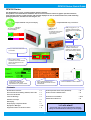
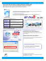
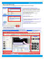
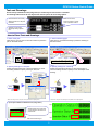
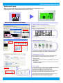
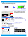
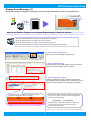
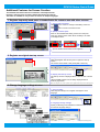
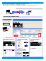
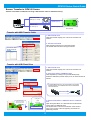
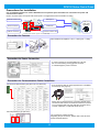
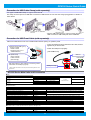
For customers who use Pro-face products for the first time –
First step of screen creation and settings
GP4100 Series
Quick Guide
3.4-inch
Compact Graphic Operator Interface
GP4100 Series
www.proface.com
GP4100 Series Quick Guide
GP4100 Series
The GP4100 Series is a 3.4” compact graphic operator interface.
This product is recommended to customers who have used interfaces other than graphic operator interfaces,
such as digital counters, signal switches and message displays for use on small machine tools, food machinery,
packaging machines, monitors for fast chargers, etc.
Compact HMI with easy-to-read display.
Compact HMI with easy connections.
- USB Type-A x 1
- USB mini-B x 1
- Serial x 1
- 200 x 80 pixel resolution
- 16 levels of grayscale
- 3-color backlight
* For supported communication
drivers, please go to our
support website.
GP-410*G
Green
Orange
Red
Pink
Red
USB
USB port
port (Type-A
(Type-A xx 1)
1) is
is
standard.
standard. ItIt allows
allows screen
screen
data
data transfer
transfer via
via aa USB
USB flash
flash
drive.
drive.
GP-410*W
White
USB
USB port
port (mini-B
(mini-B xx 1)
1) is
is
standard.
standard. ItIt allows
allows PLC
PLC
Ladder
Ladder to
to be
be edited
edited through
through
HMI.
HMI. (Pass-through
(Pass-through feature)
feature)
Easy
Easy to
to read
read small
small characters
characters
on
on switches.
switches.
Easy
Easy to
to read
read numeric
numeric
characters
characters even
even when
when several
several
values
values are
are displayed
displayed on
on the
the
same
same screen.
screen.
A
A wide
wide variety
variety of
of graphs
graphs are
are
available
available to
to provide
provide visual
visual
representation
representation of
of operation
operation status.
status.
Vertical
Vertical installation
installation is
is also
also available.
available.
Error
Error messages
messages allow
allow you
you to
to
easily
easily identify
identify what
what kinds
kinds of
of errors
errors
are
are detected.
detected.
Contents
GP4100 Series Overview
>2
Screen Operation Check on PC (Simulation)
> 12
How to Get the Screen Editing Software, GP-Pro EX
>3
Screen Transfer to GP4100 Series
> 13
How to Use GP-Pro EX
>4
Texts and Drawings
>5
Precautions for Installation
> 14-15
Switches and Lamps
>6
GP4100 Series Model List
> 15
Data Display
>7
Graph Display of Operation Status
>8
Display Error Messages
> 9-10
Supportive Features for Screen Creation
> 11
>> Let’s start!
You
You will
will learn
learn how
how to
to create
create screen
screen data
data and
and configure
configure
settings
settings for
for the
the GP4100
GP4100 Series
Series starting
starting on
on the
the next
next page.
page.
2
GP4100 Series Quick Guide
How to Get Pro-face Screen Editing Software, GP-Pro EX
GP-Pro EX Ver.2.6 or later is required to create HMI screen data for the GP4100 Series.
GP-Pro EX provides simple operation with an enhanced user interfaces.
- Free upgrade service is available to users of GP-Pro EX Ver.2.0 or later from our support site,
Otasuke Pro! (Free member registration is required.)
> http://www.pro-face.com/otasuke/
- GP-Pro EX Ver.2.6 Limited Edition is a trial software, which is also a upgrade module
for users of Ver.2.0 or earlier and for test use
•GP-Pro EX Ver.2.6 Operating Environment
OS
(64-bit OS is not
supported.)
CPU
Memory
Hard Disk Space
Windows Vista (Ultimate, Home Premium, Home Basic,
Business)
Windows XP (Home Edition, Professional Edition)
Windows 2000 (SP3 or later)
Screen
Screen Editor
Editor GP-Pro
GP-Pro EX,
EX, compatible
compatible with
with all
all Pro-face
Pro-face
products!
products!
Windows Vista: Pentium 4 1GHz or greater
Windows XP, Windows 2000: Pentium III 800MHz or greater
(Pentium 4 1.3GHz or greater recommended)
Windows Vista: 1GB or greater (2GB or greater recommenced)
Windows XP, Windows 2000: 512MB or greater (1GB or later
recommended)
720MB or greater (free space necessary for installation)
How to Install GP-Pro EX
1. Install GP-Pro EX and Transfer Tool
Start the installer, and then “SET UP MENU” appears.
Click [GP-Pro EX] to start installing the software.
In the Limited Edition, entering a serial number and key code
is not required.
After the installation of GP-Pro EX is completed, the
installation of Transfer Tool automatically starts.
After the installation of Transfer Tool is completed, restart the
PC to activate the Transfer Tool.
Transfer
Transfer Tool
Tool can
can be
be solely
solely installed.
installed.
If you would like to control editorial authority, install only
the Transfer Tool separately on PC at site. This allows
operators only to transfer screen data.
2. Completion of the installation
The GP-Pro EX icon is shown on the desktop of the PC after
the installation is completed.
3
GP4100 Series Quick Guide
How to Use GP-Pro EX
GP-Pro EX allows you to create HMI screen data and to configure settings for the GP4100 Series.
1. Start-up and default settings of GP-Pro EX
Double-click the icon on the desktop to start GP-Pro EX.
After a pop-up window appears, select [New] and specify
[Display Unit] and [Orientation] (“Landscape” or “Portrait”).
To create screen data for the GP4100 Series, select the
options for [Display Unit] as follows:
Series: GP4000 Series and then GP-41** Series
Model: GP4105 or GP-4106
2. Select a Device/PLC
Select a device or PLC connected.
For
For details
details on
on new
new and
and updated
updated drivers,
drivers, please
please go
go to
to our
our
support
support website,
website, Otasuke
Otasuke Pro!
Pro!
Æ
Æ http://www.pro-face.com/otasuke/
http://www.pro-face.com/otasuke/
3. Start the main window
Click [New Screen]. The main window appears.
GP-Pro EX Main Window
Any needed action can be carried out on the main window of GP-Pro EX.
Select an operation process.
Place drawings and parts on a base screen.
Base Screen (Drawing Area)
Select switches and lamps from the
Parts Tool Box with drag & drop.
Click the tab to change the setting items.
Choose a part to place from [Parts Tool Box].
Click the [System Settings] tab to change settings for the display
unit and peripherals.
Click the [Address] tab to see the address map.
Shortcut keys available.
4
Create screen data using icons.
Icons are freely laid out.
GP4100 Series Quick Guide
Text and Drawings
A wide variety of Windows fonts (image fonts) to create easy-to-read screens is available.
The drawing feature allows for fine layout with various options for lines and graphics.
Make
Make use
use of
of boxes,
boxes,
lines
lines and
and circles
circles to
to create
create
more
more organized
organized screens.
screens.
Small
Small characters
characters are
are clearly
clearly
displayed
displayed with
with 200
200 xx 80
80 pixel
pixel
resolution.
resolution.
Switches
Switches can
can be
be easily
easily
labeled
labeled by
by setting
setting options
options
for
for it.
it.
How to Place Texts and Drawings
1. Place a text part
Click the icon of a text part on the main window to place the
part on the base screen.
1. Select a drawing type
Click the icon of a desired drawing to place the drawing on
the base screen.
Text
Text Part
Part
Dot
Dot
Polyline
Polyline
Line
Line
2. Specify settings for a text part
Double-click the placed part or press the [F9] key to show
the setting window to specify a font type, size, etc.
Polygon
Polygon
Rectangle
Rectangle
Arc/Pie
Arc/Pie
Circle/Oval
Circle/Oval
2. Specify settings for a drawing
Double-click the placed drawing or press the [F9] key to
show the setting window to specify a color and shape of the
drawing.
[F9]
[F9]
[F9]
[F9]
* Other than using the icon, text parts can be placed from the [Draw] menu.
* Other than using the icon, drawings can be placed from the [Draw] menu.
8pt to 72pt available for Windows fonts (image fonts)
12pt
Adjusting
Adjusting text
text size,
size, more
more parts
parts
can
can be
be placed
placed in
in the
the 200
200 xx 80
80
pixel
pixel screen.
screen.
10pt
8pt
Arial, actual-size image >
5
GP4100 Series Quick Guide
Switch and Lamp
Make your choice from a wide variety of switches and lamps, such as push buttons and
toggle switches. It can be freely placed on the screen by one bit.
STOP
OK
RUN
CAUTION
NG
How to Place Switches and Lamps
1. Place a switch on the base screen
Referring to page 4, display [Parts Tool Box] on the main
window.
Select a switch part from the [Parts Tool Box], and drop
and drag it on the base screen.
16-grayscale parts downloadable from our support website,
“Otasuke Pro!”
2. Specify settings for a switch
Double-click the part to show the setting window.
Click
Click the
the icon
icon to
to select
select aa switch
switch type.
type.
If a bit switch is selected, a bit address and bit action should
be selected. The default for bit action is “Bit Momentary.”
3. Add features to a switch
Click the [Switch Common] tab to add the features to avoid
wrong operation by setting conditions of switch action.
- Interlock Feature
Operation is allowed only when a specified bit is ON or OFF.
- Delay Feature
Operation becomes enabled in a certain period of time after
a switch is touched.
4. Place a lamp
To use a part as a lamp, place a lamp by dragging and dropping
from [Parts Tool Box], or check [Lamp Feature]
in the [Lamp Feature] tab on the setting window.
When the same bit address as the switch has is specified, the
lamp reacts at the same time as the switch is touched.
In the [Color] and [Label] tabs, the settings to specify a color
when the bit is ON or OFF and texts for the label.
* Other than using the icon, switches can be placed from the [Parts] menu.
6
GP4100 Series Quick Guide
Data Display
Values stored in a connected device (such as PLC) can be displayed.
It also allows for inputting numeric characters and displaying texts too.
Voltage
Current
Display Numeric Data
How to Place Data Display
1. Place a Data Display on the base screen
Referring to page 4, display [Parts Tool Box] on the main
window.
Select a Data Display part from the [Parts Tool Box], and
drop and drag it on the base screen.
2. Specify settings for a Data Display
Double-click the part to show the setting window.
If [Text Display] is selected, text data is displayed.
For example, an error code in Hex format stored in a
connected device can be displayed as text in ASCII format.
3. Set an address in a connected device
In [Monitor Word Address], input an address of which value
is stored in a connected device.
If [Allow Input] is checked, a
keyboard can be called to input a
value and text by touch.
4. Specify a font
Click the [Display] tab to select a font type, a font size and
display digits.
Bitmap Font (Neon)
Image Font
Standard Font (7-segment)
Bitmap Font (7-segment)
Stroke Font (Outline)
Standard Font
Easy-to-read
Easy-to-read display
display of
of numeric
numeric characters
characters using
using clear
clear
bitmap
bitmap fonts
fonts and
and Windows
Windows fonts
fonts (image
(image fonts).
fonts).
* Other than using the icon, Data Display can be placed from the [Parts] menu.
7
GP4100 Series Quick Guide
Graph Display of Operation Status
Visually check operation status on screen with numerical information shown in bar or trend graphs.
Voltage
Current
Graph Display
How to Place Bar Graphs
1. Place a bar graph on the base screen
Referring to page 4, display [Parts Tool Box] on the main
window.
Select a bar graph from the [Parts Tool Box], and drop and
drag it on the base screen.
2. Specify settings for a bar graph
Double-click the part to show the setting window.
- Select a graph type
- Specify [Monitor Word Address]
In [Monitor Word Address], input an address of which
numeric data is stored in a connected device.
- Data type
Select Bin, BCD or Float to display numeric data in the
graph.
- Specify the range
Display from a minimum value to a maximum value in a
graph by percentage.
3. Specify a color
Click the [Color] tab to select a display color.
Click [Extended] to specify details on the color, for example,
to change a gradation setting for high visibility.
Display
Display graphs
graphs making
making good
good use
use of
of 16
16 levels
levels of
of grayscales.
grayscales.
Making
Making good
good use
use of
of solid
solid lines,
lines, dashed
dashed lines
lines and
and 16-grayscale
16-grayscale
display,
display, clearly
clearly display
display multiple
multiple channels
channels of
of trend
trend graphs
graphs on
on one
one
screen.
screen.
* Other than using the icon, bar graphs can be placed from the [Parts] menu.
8
GP4100 Series Quick Guide
Display Error Messages (1)
Specify alarm settings to display error messages shown by changes of bit address or data in a connected device.
Confirm the error
to see a message
エラーコード一覧
エラーコード一覧
Error Code List
6B4D
3A7E
How to Set Alarms: Register a corresponding message to each bit address
When
When the
the address
address M0000
M0000 is
is ON,
ON, display
display ”Press
”Press the
the emergency
emergency stop
stop button.”
button.”
When
When the
the address
address M0001
M0001 is
is ON,
ON, display
display ”Oil
”Oil pressure
pressure overload.”
overload.”
When
When the
the address
address M0002
M0002 is
is ON,
ON, display
display ”Exceed
”Exceed the
the maximum
maximum pressure.”
pressure.”
When
When the
the address
address M0003
M0003 is
is ON,
ON, display
display “Foreign
“Foreign material
material is
is detected.
detected. Remove
Remove itit immediately.”
immediately.”
1. Show the alarm setting screen
Click the icon to show the alarm setting screen.
2. Specify a backup history
If [Backup History] is checked, alarm records remain saved
even after a GP4100 Series unit is turned OFF.
3. Specify settings for an alarm
Register bit addresses, trigger conditions and messages.
The registered alarm information can be grouped into up to 8
blocks by setting addresses and messages in each block.
A
A long
long message
message can
can be
be displayed
displayed on
on screen
screen as
as aa banner
banner
message
message scrolled
scrolled at
at the
the bottom
bottom of
of the
the screen.
screen.
IfIf [Word
[Word Monitoring]
Monitoring] is
is selected,
selected, messages
messages are
are registered
registered
to
to be
be shown
shown on
on screen
screen in
in accordance
accordance with
with changes
changes of
of data
data
values
values in
in aa connected
connected device.
device.
IfIf [Bit
[Bit Monitoring]
Monitoring] is
is selected,
selected, messages
messages are
are registered
registered to
to
be
be shown
shown on
on screen
screen in
in accordance
accordance with
with changes
changes of
of
corresponding
corresponding bit
bit addresses.
addresses.
* Other than using the icon, alarm settings can be made from the [Common Settings] menu.
9
GP4100 Series Quick Guide
Display Error Messages (2)
>>
IfIf the
the [Clock
[Clock Update
Update Setting]
Setting] icon
icon is
is clicked,
clicked, aa
GP4100
GP4100 unit
unit synchronizes
synchronizes its
its clock
clock with
with that
that
in
in aa connected
connected device.
device.
No.1: Over current of the heater
The GP4100 Series can be used as a message display,
enlarging a message on the entire screen.
How to Set Alarms: Specify how to display messages
1. Place an Alarm Display
Click the [Alarm] icon to place an Alarm Display on the base
screen. Double-click the placed part to show the setting
window.
2. Specify settings for an Alarm Display
Select a block in which necessary alarm information is
registered in [Display Block].
In [Display Alarms], select the number of alarm messages to
be displayed at once.
To
To use
use aa GP4100
GP4100 unit
unit as
as aa message
message display,
display, select
select “1”
“1” in
in
[Display
[Display Alarms]
Alarms] in
in [Display
[Display Format].
Format].
3. Specify the number of characters
Select the number of characters for one line in each item to be
displayed.
If any one of [Date], [Trigger], [Acknowledged] and [Recovery]
is selected, it is displayed in a selected format according to the
alarm triggered.
To
To use
use aa GP4100
GP4100 unit
unit as
as aa message
message display,
display, check
check only
only
[Message]
[Message] in
in [Display
[Display Characters].
Characters].
An enlarged
message can be
placed on the entire
base screen.
4. Specify settings for display
Select a color, font and frame for an Alarm Display to display
an easy-to-read message using image fonts.
5. Place and specify a special switch to scroll a message list
Use a special switch to scroll up/down multiple alarm messages.
Select a switch part from the [Parts Tool Box], and drop and
drag it on the base screen. Double-click the part to set it as an
alarm history switch. If one of following options is selected,
scrolling up/down messages is available.
[Start]
: To enable an alarm history switch.
[Move Upward/Downward]: Scroll up/down messages by touch
IfIf [No
[No Shape]
Shape] is
is selected
selected for
for the
the shape
shape of
of aa [Start]
[Start] switch
switch and
and
this
this switch
switch is
is put
put over
over the
the [Move
[Move Upward]
Upward] and
and [Move
[Move
Downward]
Downward] switches,
switches, the
the screen
screen space
space can
can be
be saved.
saved.
* Other than using the icon, alarms can be placed from the [Parts] menu.
10
GP4100 Series Quick Guide
Additional Features for Screen Creation
The Header/Footer feature allows for reduction of development time.
Register a start-up screen to utilize a waiting time during the start-up.
Text Table is available for easy creation of screens in multiple languages.
1.
Register frequently used parts in header/footer for common use with other screens
1. Set a header and footer
Click
on the screen to change to the editing screen for
header/footer.
Click
again to return to the base screen.
2. Specify common parts
Place on the header/footer editing screen texts and parts
such as a change screen switch which are likely to be used
on multiple screens.
Up
Up to
to 20
20 headers
headers and
and 20
20 footers
footers can
can be
be registered.
registered.
2. Register an original start-up screen
1. Register a start-up screen
Click the [Register Start Screen] icon to register a start-up
screen.
The screen size is W200 x H80 pixels (W80 x H32 mm).
2. Display the start-up screen
The start-up screen is displayed when a GP4100 unit is turned
ON.
JPEG and BMP images can be clearly displayed with 16
levels of grayscales.
* Other than using the icon, a start-up screen can be registered from the [Common Settings] menu.
3. Change language settings at once
1. Set a text table
Click the [Text Table] icon to register messages in each
language.
Japanese
2. Language change settings
Specify a switching control address in where the table number
is stored for language change.
English
Chinese
Korean
* Other than using the icon, a text table can be registered from the [Common Settings] menu.
11
GP4100 Series Quick Guide
Screen Operation Check on PC (Simulation)
Screen operations can be tested on a PC before HMI software application is transferred to a GP4100 unit.
Neither
Neither aa GP4100
GP4100 unit
unit nor
nor aa USB
USB Transfer
Transfer Cable
Cable is
is required
required for
for the
the simulation.
simulation.
How to Use the Simulation Feature
To start a simulation, click the [Simulation] icon or press the [F12] key on PC.
(1)
[F12]
(2)
(3)
1. Switch Operation
Switch operation can be confirmed
with a mouse click.
2. Lamp ON/OFF Operation
Lamp operation can be confirmed
by changing the status of registered
bit addresses.
3. Alarm Messages
Alarms can be confirmed by
changing the status of registered
addresses.
OFF
OFF Æ
Æ ON
ON
Operations of Data Displays and
graphs can be confirmed by
changing values of registered
word addresses.
0→500
0→500
12
Banner messages scrolling can
be confirmed too.
GP4100 Series Quick Guide
Screen Transfer to GP4100 Series
Transfer screen data to a GP4100 unit using a USB Transfer Cable or USB flash memory.
USB Transfer Cable
(USB Type A - mini B)
USB Port (mini B)
USB Flash Drive
USB Port (Type A)
(for USB Type A)
GP4100 Series
Transfer with USB Transfer Cable
1. Start Transfer Tool
Click the [Transfer Project] icon to show the Transfer Tool
window.
2. Transfer screen data
Click the [Send Project] icon to start the transfer.
The transfer status is shown during the transfer.
The
The transfer
transfer status
status is
is
shown
shown during
during the
the
transfer.
transfer.
Transfer with USB Flash Drive
1. Start Transfer Tool
Click the [Transfer Project] icon to show the Transfer Tool
window.
2. Save screen data to a USB flash drive
Click the [Memory Loader] icon to [Create Backup File].
Select the destination (a drive name) on PC to create the data to
transfer.
IfIf Toshiba
Toshiba Machine’s
Machine’s PLC
PLC (TC
(TC mini/TC200)
mini/TC200) is
is connected,
connected,
aa ladder
ladder program
program in
in aa USB
USB flash
flash drive
drive can
can be
be transferred
transferred
via
via aa GP4100
GP4100 unit.
unit.
Screen data/ Ladder
Alternately press
each of two corners
opposing each other.
System Menu
|
[USB]
|
[Download]
3. Download the data in a USB flash drive to a GP4100
unit
Open the System Menu on a GP4100 unit to download the
screen data in a USB flash drive.
The System Menu is shown at the bottom of the screen if
each of two corners of the unit opposing each other are
alternately pressed.
System Menu
13
GP4100 Series Quick Guide
Precautions for Installation
Use an installation fastener to install a GP4100 unit on a operation panel and make wire connections for power and
communication cables.
(Caution: To prevent electric shock, please make sure the power is not supplied while the above installations are made.)
USB
USB Type
Type A
A
Power
Power Connector
Connector
USB
USB mini
mini B
B
Fastener
Fastener Insertion
Insertion Slot
Slot
COM
COM I/F
I/F Connector
Connector **
USB
USB Front
Front
Cable
Cable (sold
(sold
separately)
separately)
Fastener
Fastener Insertion
Insertion Slot
Slot
* RS-232C and RS-422/485 Types(GP-4105, and GP-4106)
Precaution for Fastener
- Panel thickness acceptable: 1.0mm - 5.0mm [0.04 – 0.20in]
Precaution for Power Connection
- A power connector is not removable from a GP unit.
Do not unnecessarily pull or jiggle the connector.
It could damage the power connector.
Precaution for Communication Cable Connection
RS-232C and RS-422/485 Types (GP-4105, and GP-4106)
- PLC connection cable for each supported PLC is available
as accessory (see page 15).
Please refer to the Device/PLC Connection Manual for the
connections with other PLCs. Make sure that the connector
is not connected with a GP unit while the connector wiring
is made. Otherwise, it could lead electric shock.
RS-485 (isolation) Type (GP-4107)
The connector is D-Sub9 (socket).
Regarding the pin connection, please refer to the GP-4100
Series Hardware Manual.
14
GP4100 Series Quick Guide
Precaution for USB Cable Clamp (sold separately)
Two types of USB Cable Clamp: for Type A and for mini B.
This clamp is used to prevent a USB cable connected to USB Interface of a GP unit from being unplugged due to vibration or
other causes.
- When a USB Cable Clamp for Type A is used, remove a
USB cover from a USB holder prior to the installation.
Precaution for USB Front Cable (sold separately)
USB Front Cable allows for the use of USB interface without opening an operation panel.
- Only if the waterproof cap is attached to this cable, IP65f is
applied only to the front side.
USB
USB Flash
Flash Drive
Drive (USB
(USB Type
Type A)
A)
-- Screen
Screen Transfer
Transfer
-- Ladder
Ladder Transfer
Transfer
(Supporting
(Supporting only
only PLC
PLC of
of
Toshiba
Toshiba Machine)
Machine)
- Fasten the waterproof cap tightly.
[CA5-USBEXT-01]
USB
USB Port
Port
PC
PC (USB
(USB mini
mini B)
B)
-- Screen
Screen Transfer
Transfer
-- Ladder
Ladder Transfer
Transfer
(Pass-through)
(Pass-through)
Code Reader
Easy
Easy data
data reading
reading by
by easy
easy settings
settings of
of connecting
connecting aa USB
USB
code
code reader
reader to
to aa USB
USB port
port (Type
(Type A).
A).
Waterproof
Waterproof Cap
Cap
** When
When aa USB
USB code
code reader
reader is
is used,
used, the
the power
power should
should be
be supplied
supplied via
via aa selfselfpowered
powered hub.
hub.
USB Flash Drive
GP4100 Series Main Units and Accessories
■Units
Product Name
Model No.
Backlight
GP-4105G
GP4105G1D
GP-4105W
GP4105W1D
White/Pink/Red
GP-4106G
GP4106G1D
Green/Orange/Red
GP-4106W
GP4106W1D
White/Pink/Red
GP-4107G
GP4106G1D
Green/Orange/Red
GP-4107W
GP4106W1D
White/Pink/Red
Display Type
Serial (COM1)
Green/Orange/Red
RS-232C
3.4" STN
Monochrome LED
RS-422/485
RS-485 (isolation)
■Optional Products
Product Name
Model No.
Description
Screen-creation software (Ver.2.6 or later required to use GP4100 series)
GP-Pro EX
EX-ED-V26
USB Transfer Cable (USB A/mini-B) (1.8 m)
ZC9USCBMB1
Cable for transferring screen data from a PC (Type-A) to the GP (USB mini-B)
Mitsubishi PLC Q-Series CPU I/F Cable (3 m)
ZC9CBQ31
Connects the GP directly to the CPU programming port on the Mitsubishi Electric PLC Q series
Mitsubishi PLC FX-Series CPU I/F Cable (5 m)
ZC9CBFX51
Mitsubishi PLC FX-Series CPU I/F Cable (1 m)
ZC9CBFX11
Mitsubishi PLC A-Series Cable (5 m)
Panasonic Electonic Works PLC Series CPU Cable (2m)
ZC9CBA51
ZC9CBFP21
Connects the GP directly to the CPU programming port on the Mitsubishi Electric PLC A/QnA series
USB Panel-mount Extension Cable (USB mini-B 1m)
ZC9USEXMB1
Extension cable attaching to the USB (mini-B) port on the front side of the operation panel
USB Panel-mount Extension Cable (USB Type A 1m)
CA5-USBEXT-01
Extension cable attaching to the USB (Type-A) port on the front side of the operation panel
USB-Serial (RS-232C) Conversion Cable (0.5m)
CA6-USB232-01
Cable for converting a GP unit’s USB interface (Type-A) into a serial interface (RS-232C)
3.4-inch Screen Protection Sheet
ZC9DS31
Disposable, dirt-resistant sheet for the GP unit’s screen (5 sheets/set)
USB Clamp TypeA (1 Port)
ZC9USCL1
USB (Type A) Cable clamp for 1 port products to prevent disconnection (5 pcs/set)
USB Clamp Type mini-B (1port)
ZC9USCLMB1
USB (mini-B) Cable clamp for 1 port products to prevent disconnection (5 pcs/set)
Connect the GP directly to the CPU programming port on the Mitsubishi Electric Mitsubishi PLC FX-Series PLC FX series
Connects the GP directly to the CPU port on the Panasonic Electric Works PLC FP series
■Maintenance Items *Please purchase when the product is damage or lost.
Product Name
3.4-inch Installation Fastener
Model No.
Description
ZC9AF31
Used to install the GP into a solid panel (2 pcs/set)
3.4-inch Installation Gasket
ZC9WG31
Provides dust and moisture resistance when GP is installed into a solid panel (1 piece)
3.4-inch COM I/F Connector
ZC9CMC1
Connector for Serial I/F ( 1 piece)
15
GP4100 Series Quick Guide
“Otasuke Pro!” supports you with a full range of services!
> http://www.pro-face.com/otasuke/
The content of our “Otasuke Pro!” support site has been
upgraded with services aimed at reducing development time
by including contents such as Q&A and manual downloads.
Our Support site is designed to help you
Maximize the value of your Pro-face HMI.
Download items:
- Manuals
- Samples
- Updates / Drivers
Everything you need is here!
Tips and tricks, Learning Center, - Certificate PDF for
international Standards
Educational videos and more!
Pro-face is a registered trademark of Digital Electronics Corporation in
Japan, U.S.A., Canada, Europe and other areas and countries.
Global Head Office
North/ South America
European Head Office
Digital Electronics Corporation
[JAPAN]
Tel: +81-(0)6-6613-3111
Pro-face America, Inc.
[U.S.A.]
Tel: +1-734-429-4971
Pro-face Europe B.V.
[THE NETHERLANDS]
Tel: +31 (0)23 55 44 099
[AUSTRALIA] Tel: +61-(0)3-9550-7395
[CHINA] Tel: +86-(0)21-6361-5175
[ENGLAND] Tel: +44 (0) 2476 511288
[GERMANY] Tel: +49 (0)212 258 260
[ITALY] Tel: +39 0362 59 96 1
[RUSSIA] Tel: +007 (812) 336-47-06
[SPAIN] Tel: +34 (0)93 846 07 45
[SWITZERLAND] Tel: +41 (0)43 343 7272
[THAILAND] Tell: +66-(0)2-617-5678
Copyright 2010 Digital Electronics Corporation. All rights reserved.
16
[AUSTRIA ] Tel: +43 7236 3343 620
[DENMARK ] Tel: +45 70 22 01 22
[FRANCE] Tel: +33 (0)1 60 212291
[INDIA] Tel: +91 80 4011 8050, 8033
[POLAND] Tel: +48 (22) 465-66-62
[SOUTH KOREA] Tel: +82-(0)2-2630-9850
[SWEDEN] Tel : +46 46 540 90 70
[TAIWAN] Tel: +886-(0)2-2657-1121
www.proface.com
DT/DT1002-GP4100GUIDE-01E00