1
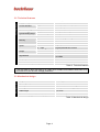
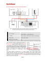
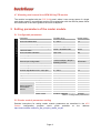
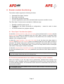
AREM 80 SmylTR MREM 80 SmylTR APS mini / APS mini Plus reader modules for IPDP Slim panels User’s guide ® © 2004 – 2012, TECH FASS s.r.o., Věštínská 1611/19, 153 00 Prague, Czech Republic, www.techfass.cz, [email protected] (Date of release: 01-03-2011, valid for FW version 5.08) 1 Content 1 Content ....................................................................................................................... 2 2 Product Description .................................................................................................... 3 3 Technical parameters ................................................................................................. 3 3.1 Product version .................................................................................................... 3 3.2 Technical features................................................................................................ 4 3.3 Mechanical design ............................................................................................... 4 4 Installation .................................................................................................................. 5 4.1 Reader module description .................................................................................. 5 4.2 C1 and C2 cable wiring description ...................................................................... 5 4.3 Connecting the reader module with panel ............................................................ 6 4.4 Standard connection ............................................................................................ 7 4.5 D1 LED Indication ................................................................................................ 7 4.6 Installation instructions......................................................................................... 7 4.7 Mounting and removal the xREM 80 SmylTR module .......................................... 8 5 Setting parameters of the reader module .................................................................... 8 5.1 Configurable parameters...................................................................................... 8 5.2 Reader module parameters setting ...................................................................... 8 6 Reader module functioning ......................................................................................... 9 6.1 “Door Open” function description ......................................................................... 9 6.2 Function permanent door lock release according to a time schedule ................... 9 6.3 Alarm states ....................................................................................................... 10 6.4 Standard operating modes ................................................................................. 11 6.5 Read ID media format ........................................................................................ 11 6.6 Programming mode ........................................................................................... 11 6.7 ID expiration function ......................................................................................... 15 6.8 ID with Alarm flag function ................................................................................. 15 6.9 Antipassback function ........................................................................................ 15 6.10 Disabling function............................................................................................... 16 7 Simplified access rights evaluation ........................................................................... 17 8 Useful links ............................................................................................................... 17 All brand or product names are or may be trademarks of, and are used to identify products and services of, their respective owners. 2 Product Description The xREM 80 SmylTR 1) reader modules (125 kHz readers with an embedded single door controller) are designed for connection to the RS 485 bus of the APS mini / APS mini Plus access control system. It is possible to connect up to 32 reader modules to a single line of the APS mini / APS mini Plus system. In effect the number of lines is not limited. The reader modules are designed for installation in IPDP Slim entry panels of ALPHATECH TECHNOLOGIES s.r.o. audio and video systems (design as Smyle entry panels of Urmet company), where it occupies space of a single push button. The module comes in an adjusted transparent button suitable for installation in the panel. 1) Pic. 1: xREM 80 SmylTR Commercial designation of available versions is described in table 1. 3 Technical parameters IPDP Slim IPDP Slim IPDP Slim IPDP Slim 52480200 52480201 53480200 53480201 2) MLE AREM 80 SmylTR – TF AREM 80 SmylTR – EM MREM 80 SmylTR – TF MREM 80 SmylTR – EM HID Catalogue number Module features 2) EM Product designation Module designed for panel TF Product version 3.1 Product version Table 1: Product version TF – TECHFASS factory ID media reading; EM – EM Marin ID media reading; HID – HID Proximity ID media reading; MLE – events archive reading availability (upgradable) Page 3 Technical features 3.2 Technical features Supply voltage Current demand Typical Maximal Version with keypad ID technology, typical reading range EM Marin HID Proximity Real-time clock Memory Inputs Output Cards Events Time schedules Door status 2nd input Door lock 3) Alarm 8 ÷ 28 VDC 60 mA (12 V), 25 mA (28 V) 90 mA (8 V) N/A 5 cm (with ISO card) 4 cm (with ISO card) Yes 748 ID, 2 programming cards 4,700 64 Logical potential-free contact Logical potential-free contact 1x open collector 0V active, max. 2A, 24V N/A 1x LED 1x PIEZO N/A RS 485 N/A Signalization Tamper protection Communication interface Alternative data input / output Table 2: Technical features 3) The DC type of door lock has to be used only! Suitable anti-parallel diode has to be connected to its coil as over-voltage protection. Mechanical design 3.3 Mechanical design Weight 0.017 kg Operating temperature Humidity -25 ÷ 60 °C Max. 95%, non-condensing Housing Cable length Color Dimensions (Height x Width x Depth) IP 44 (built in the entry panel) 2x 0.4 m White / transparent 21x85x21 mm Table 3: Mechanical design Page 4 4 Installation 4.1 Reader module description C1 C2 D1 Description Pic. 2: xREM 80 reader module, front (left) and rear (right) view Designation Purpose C1 Connector for C1 cable (5-wires) connection C2 Connector for C2 cable (3-wires) connection D1 Red-green LED indicator Table 4: Connectors and LED indicators description Wiring description 4.2 C1 and C2 cable wiring description C1 cable Color White Black Grey Brown Orange C2 cable Color Grey Red Blue Function B wire - RS485 line A wire - RS485 line 0 V (GND) Input 1 (IN1) Input 2 (IN2) Function 0 V (GND) Power supply +8 ÷ +28VDC Output 1 - OC Table 5: C1 and C2 cable wiring description All unused wires must be mutually isolated! Page 5 4.3 Connecting the reader module with panel Standard connection Pic. 3: Standard reader module connection with use of DC power supply and the lock opening contact of the IPDP Slim entry panel Signal + 8 ÷ + 28 VDC 0 V (GND) Release lock from panel, 0 VDC active Release lock from reader Connection + contact (power supplier unit), red wire of C2 cable (reader module), + contact (door lock) - contact (power supplier unit), grey wire of C2 cable (reader module), COM contact of relay 1 (entry panel) NO contact of relay 1 (entry panel), orange wire of C1 cable (reader module) Blue wire of C2 cable (reader module), - contact (door lock) Table 6: Standard reader module connection using the entry panel door lock release signal This connection requires configuring the function of the second input of the reader module as Request to exit button (default module setting, see pic. 4). The standard entry panel door lock release signal is used as a signal for the reader module (orange wire) to release the door lock then. The door lock release is controlled by the output of the reader module (open collector, 0 V (GND) active – blue wire). Pic. 4: Reader module setting The reader module is powered by a DC power supplier. When using suitable power supplier and door lock type, you can power all components (entry panel, reader module and door lock) from a single power supplier. If an AC powered door lock must be used, it is necessary to use an individual external relay controlled by the OC signal from the reader module to control the door lock. Page 6 Connection 4.4 Standard connection Input 1 Door contact, active when door closed Input 2 Request to exit button or handle contact, 0 V) when button or handle active; Tamper; Disabling function Output 1 (OC) Door lock control open collector Table 7: Standard connection The door monitoring contact (IN1) is operational after its first change of status since switching on the module. Full door lock timing acc. to tab. 8 is used when the door status contact is not installed and no Door Forced and Door Ajar alarms are triggered. LED indicators 4.5 D1 LED Indication Red Yellow Continuously lit Flashing with 4 s period Fast switching with green Continuously lit Flashing Green Online operating mode via RS 485 Offline operating mode Address setting mode Programming mode Indicating door lock release ID media reading Table 8: LED indicators 4.6 Installation instructions The reader module uses passive RF/ID technology, which is sensitive to RF noise sources. Noise sources are generally of two types: radiating or conducting. Conducted noise enters the reader via wires from the power supply or the host. Sometimes, switching power supplies generate enough noise to cause reader malfunction, it is recommended to use linear system power supplies. Radiated noise is transmitted through the air. It can be caused by computer monitors or other electrical equipment generating electromagnetic fields. Consequently, a short distance between the reader modules themselves can cause reading malfunctions – for correct operation it is necessary to keep a minimum distance of 50 cm. Various metallic constructions may have a negative influence on this distance; if there are any doubts, it is recommended to perform a practical test before final mounting. Nearby metal surfaces may cause a decrease in reading distance and speed. This is caused by the combined effects of parasitic capacitance and conductance. Page 7 4.7 Mounting and removal the xREM 80 SmylTR module The module is supplied with the IPDP SLIM panel, where it can occupy space of a single push button space in a predefined position. For manipulation with the devices please follow the instructions in the user’s guide to the IPDP SLIM panel. 5 Setting parameters of the reader module Configurable parameters 5.1 Configurable parameters Parameter Door lock release time Door lock control setting Door lock relay function setting Permanent door lock release according to a time schedule Door lock status indication Acoustic signal of door lock release Door ajar time Second input configuration Acoustic signalization time - Tamper Acoustic signalization time - Forced door Acoustic signalization time – Door ajar Acoustic signalization time – APB alarm Signalization time – Card alarm Antipassback function setting Automatic summer time adjustment Door opened Door closed Saving events in Input 2 On the module’s Input 2 Off archive Strike released Strike closed Possible range 0 255 s Direct / reverse Standard / toggle / pulse Default setting 7s Direct Standard Never / Schedule index Never YES / NO YES / NO NO YES 20 s 0 255 s REX button / handle contact / external tamper / tamper / disabling function 0 255 s REX button 30 s 30 s 0s 0 255 s 0 255 s 0 255 s 0 255 s See chapter 6.10 YES / NO Enabled / Disabled Enabled / Disabled Enabled / Disabled Enabled / Disabled Enabled / Disabled Enabled / Disabled 0s 30 s Disabled YES Enabled Enabled Enabled Enabled Enabled Enabled Table 9: Configurable parameters 5.2 Reader module parameters setting Detailed instructions for setting reader module parameters are described in the APS Reader configuration program user’s guide available at the address http://www.techfass.cz/files/m_aps_miniplus_reader_en.pdf. Page 8 6 Reader module functioning The reader module supports the following functions: Standard “Door Open” function. Door status monitoring. Exit-devices contact monitoring. Acoustic signalization (and online) activated when any alarm condition occurs. The “Door Open” function can be activated in 3 different ways: Reading a valid ID (card, key fob…). Pressing the exit button (according to configuration) – cannot be used in alarm condition. Via communication line (program request). 6.1 “Door Open” function description In case the standard function of the door lock relay is set, the door lock is released and the beeper activated (when not disabled) when the “Door Open“ function is activated. Both outputs stay active until the door is opened or the preset door lock release time has elapsed - see configuration table. In case the toggle function of the door lock relay is set, the door lock relay status is switched and the beeper is activated (when not disabled) when the “Door Open” function is activated. The beeper stays active until the door is opened or the preset door lock release time has elapsed - see configuration table. The door lock relay status remains unchanged until another “Door Open” function is activated. In case the pulse function of the door lock relay is set, the door lock relay status is switched for the time defined by the Pulse width parameter (ms) after the Door Open function is activated. In case the standard function of the door lock relay is set, reading a valid card during door lock release resets the door lock release time. 6.2 Function permanent door lock release according to a time schedule When the function is set, the door lock is permanently released when relevant time schedule is valid. Reading a valid ID is standardly announced via the communication line (in online operating mode). The forced door alarm cannot be raised when the door lock is permanently released. The permanent door lock release function and the toggle function of the door lock relay are mutually exclusive. Page 9 6.3 Alarm states The reader module can get in following alarm states: 1) 2) 3) 4) 5) Tamper alarm Forced door alarm Door ajar alarm Antipassback alarm (Time APB alarm, Zone APB alarm) ID with Alarm flag alarm Alarm state reporting is performed as follows: Via communication line (statuses 1, 2, 3, 4, 5) By acoustic signal (beeper) (statuses 1, 2, 3, 4). Alarm signaling via communication line requires online running PC with relevant software suitable for online operation (APS Administrator). Two ways of acoustic signaling is carried out: Steady signal (tamper). Intermittent signal (forced door and/or door ajar, APB alarm). Acoustic alarm signaling is stopped after a valid ID is presented or pre-set time interval is elapsed, see the configuration table. If any of the relevant alarm states (with setting of the signaling timer > 0) occurs, the alarm state is announced on the communication line. After terminating all alarm conditions the alarm status announcement is deactivated. The alarm signaling is triggered by any alarm condition. 6.3.1 Tamper alarm In case of tampering the module (by tearing-off or opening the cover or changing the status of input 2 in proper configuration) the “Tamper” state is activated 3). 3) The Tamper alarm handling is operational after their first change of status since switching on the module. There is no need to configure the module when the tamper protection is not used. 6.3.2 Forced Door alarm The “Forced Door” alarm state is activated when the door is opened without activating the “Door Open” function. The only exception is opening the door with the second module input IN2 active and configured as a handle contact. 6.3.3 Door Ajar alarm If the door stays open until the pre-defined Door ajar timeout expires – see Tab. 9, the “Door Ajar“ alarm is activated. Page 10 6.3.4 Antipassback alarm The Antipassback alarm is raised when an ID is read during the Time APB counter is running or when the ID is blocked by a Zone APB. 6.3.5 ID with Alarm flag alarm ID with Alarm flag alarm occurs when an ID with the Alarm flag is read. 6.3.6 Reading ID during alarm state Reading an ID doesn’t affect the alarm state, reading a valid ID only terminates the acoustic alarm announcement followed by “Door Open” function. Reading an invalid ID only interrupts the acoustic announcement of the alarm state while signalizing “Invalid ID”. 6.4 Standard operating modes The reader module can be in either online or offline operating mode. The module’s functionality is identical in both operating modes; the events archive is read from the reader module’s memory when the module goes online.. When a programming card is read (while in either online or offline mode), the module goes into programming mode. 6.5 Read ID media format 6.5.1 EM Marin ID media format The EM Marin ID media format can be changed into selected 24, 32 or 40 bits length of ID code. The default length is 40 bits. This setting is only used when unifying of the ID media codes length is required – in combined systems with WIEGAND output readers with a fixed WIEGAND data format IDs (more information in APS Reader user’s guide available at http://www.techfass.cz/files/m_aps_miniplus_reader_en.pdf). 6.5.2 HID Proximity ID media format When working with HID Proximity technology ID media, the module operates with a code in a recognized 26 or 32 bit format, in other cases it uses all 45 bits of a media (45bit raw format). If a specific format of the HID Proximity IDs is required, it can be performed by setting up the user’s configuration of read IDs (more information in APS Reader user’s guide available at http://www.techfass.cz/files/m_aps_miniplus_reader_en.pdf). 6.6 Programming mode The module enters programming mode by reading one of the two programming cards (cards “+” and “-“). The programming mode cannot be entered while the module is in hardware address setting mode (for modules with HW address setting via the communication line). The module’s functionality in programming mode can be seen in pictures 5 a-d. It is not possible to use time schedules when inserting cards in programming mode, therefore cards are always valid. Page 11 6.6.1 Inserting cards into the reader’s memory Follow these steps for inserting cards into the reader module’s memory: Step 1 Step 2 Step 3 Read the programming card for inserting: the reader goes into programming mode. One by one, read the cards which are to be granted access. About 15 seconds after inserting the last card the reader module goes back into standard operating mode. Pic.5 a): Inserting cards 6.6.2 Deleting cards from the reader’s memory For deleting the cards from the reader module’s memory use following steps: Step 1 Step 2 Step 3 Read the programming card for deleting: the reader goes into programming mode. One by one, read the cards which are to have their access revoked. About 15 seconds after deleting the last card the reader module goes back into standard operating mode. Pic.5 b): Deleting cards Page 12 6.6.3 Deleting cards „above or below“ If a user loses his ID medium, it is usually impossible to delete the ID from the memory with the procedure described in the previous chapter, since the medium is no longer available (with an exception of entering the code at the keypad). Following procedure can be used for deleting such ID. The procedure requires using an ID medium, which was inserted right before or right after the ID medium, which should be deleted. Step 1 Step 2 Step 3 Read the programming card for inserting: the reader goes into programming mode, which is indicated by slow flashing of yellow LED. Read the programming card for inserting 5 times in a row; the reader will go into Deleting cards “above or below” mode indicated by fast flashing of yellow LED. Read a card, which is located in the module’s memory right before or right after the card you wish to delete. After this step the module quickly flashes with yellow LED. Step 4 - A Step 4 - B Step 5 For deleting an ID located right after the ID used in precious step, read the programming card for inserting. The reader module goes back into standard operating mode. For deleting an right before the precious step, programming deleting. ID located ID used in read the card for Pic.5 c): Deleting cards “above or below” Page 13 6.6.4 Deleting all cards from the reader’s memory Follow these steps for deleting all cards from the reader module’s memory: Step 1 Step 2 Step 3 5x Read the programming card for deleting: the reader goes into programming mode. Read the programming card for deleting 5 times in a row; the reader will erase all cards from its memory. The reader module goes back into standard operating mode. Pic.5 d): Deleting all cards 6.6.5 Recommended method for access rights management (using prog. cards) In case of managing access rights of plenty of users (using programming cards only), it is appropriate to establish a table, which summarizes operation with the reader module memory. All operations (adding and deleting cards) should be stored in the table. Following example shows correct usage of the programming cards and proper filing of the actions: Inserting 5 new cards using the procedure from chapter 6.6.1 – Read + (inserting) programming card, read cards 1-5, after 15 s the programming mode is exited, create a table. position 1 2 3 4 5 card card 1 card 2 card 3 card 4 card 5 Pic.5 e): Table after inserting 5 cards Card 3 gets lost – Delete it using the card 4, which is available, and using the procedure from chapter 6.6.3 – Read + (inserting) programming card, then 5x + (inserting) programming card again, then card 4, and finally – (deleting) programming card. Register the change in your table. position 1 2 3 4 5 card card 1 card 2 card 3 (lost) card 4 (available) card 5 position 1 2 3 4 5 card card 1 card 2 card 3 card 4 card 5 Pic.5 f): Deleting card 3 using the card 4, table after deleting card 3 Page 14 Card 4 gets lost – Delete it using the card 2, which is available, and using the procedure from chapter 6.6.3 – Read + (inserting) programming card, then 5x + (inserting) programming card again, then card 2, and finally + (inserting) programming card again. Register the change in your table. position 1 2 3 4 5 card card 1 card 2 (available) card 3 card 4 (lost) card 5 position 1 2 3 4 5 card card 1 card 2 card 3 card 4 card 5 Pic.5 g): Deleting card 4 using the card 2, table after deleting card 4 It is necessary to add another card (card 6). We proceed with the procedure from chapter 6.6.1 again. 1 – Read + (inserting) programming card, read cards 1-5, after 15 s the programming mode is exited. Register the change in your table. position 1 2 3 4 5 6 card card 1 card 2 card 3 card 4 card 5 card 6 Pic. 5 h): Table after inserting card 6 A new card is always inserted at the position after the last inserted card. In case of deleting all cards using the procedure described in chapter 6.6.4, it is necessary to create a new filing table. 6.7 ID expiration function This function is implemented since the FW version 5.0. It is possible to set an Expiration date for every ID stored in the module. When the date occurs, the ID becomes invalid (expired). The expiration evaluation is performed on every date change in the module’s RTC and when the access rights are downloaded. 6.8 ID with Alarm flag function This function is implemented since the FW version 5.0. It is possible so set an Alarm – ID flag for every ID stored in the module. When the ID is read, relevant alarm is raised for preset time. 6.9 Antipassback function This function is implemented since the FW version 5.0. The Antipassback function is defined in two ways: Page 15 Time APB – user cannot repeatedly use his ID for defined time Zone APB – user cannot repeatedly enter an area, where he is already present The Antipassback function is used only for the users, whose access is driven by a time schedule. The users with access always granted are not affected by the Antipassback function. The Antipassback flags for an ID can be reset by inserting the ID again with use of the programming cards (offline solution). All Antipassback flags are also reset whenever new access rights data are downloaded from the program. Both Zone and Time Antipassback flags are written either immediately after an ID is read, or after relevant door is opened (relevant input is disconnected). 6.9.1 Time Antipassback The Time Antipassback is defined by the ABP timer initial value (in minutes), which is set to the ID after passing at the reader module. If the users uses the ID at the address during the timer for the ID is running, the Time APB alarm is raised. Following parameters affect the Time APB function: APB timer initial value – defines the Time APB flag (timer) value set to the ID after passing at the reader module. If a user uses the ID again before the timer elapses, Time APB alarm is raised. Open door after APB time alarm – if the option is enabled, the Door open function is performed after the Time APB alarm is raised. 6.9.2 Zone Antipassback The Zone Antipassback is defined by enabling the option for the relevant address. The Zone APB flag is set for the ID when passing at the reader module. If a user uses the ID again when the Zone APB flag is set, the Zone APB alarm is raised. Following parameters affect the Zone APB function: 6.10 Enabled – enable/disable general Zone APB flag setting. Enable in offline mode – if the option is not set, the module operates in offline mode like if the APB function was not implemented. Open door after APB Zone alarm – if the option is enabled, the Door open function is performed after the Zone APB alarm is raised. Disabling function This function is implemented since the FW version 5.08. The module disabling function can be set at the second input. The logic of the function is configurable. The module behavior is as described below when the disabling function is active: User with access driven by a time schedule cannot run the door open function User with access always granted is not affected by the disabling function Remote door open function cannot be performed Remote identification with ID is disabled for users with access driven by a time schedule Page 16 The disabling status changes and disabled actions are logged in the events archive. 7 Simplified access rights evaluation The model of access rights contains time schedules and a table of holidays. A block diagram for access right evaluation can be seen in Pic.6. READING ID YES ID FOUND NO YES A CCESS DRIV EN B Y TIM E SCH ED. NO NO HOLIDAY? YES YES A CCESS ALWA YS GRA NTED NO NO AC CESS GRANTED FOR A CTUAL DAY & TIME YES NO ACCE SS GR ANTED FOR HOLI DAY AND A CTUAL TIME YES UNKNOWN INVALID VALID Pic. 6: Simplified access rights evaluation 8 Useful links Wiring diagrams: http://techfass.cz/diagrams-aps-mini-plus-en.html Program equipment: http://techfass.cz/software-and-documentation-en.html Page 17