1
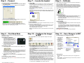
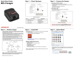
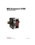
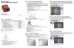
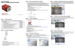
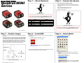
Step 2 — Connect the System
Connecting by RS-232 / RS-422 / RS-485
1
2
3
Scanner
6
Host
Quadrus MINI
Series
Step 1 — Check Hardware
4
Network
Quick Start Guide
• Connect the imager (1) to the IB-131/IC-332 interface (2) and (3).
• Connect the communication cable (6) to the host, and to the host port
on the IB-131.
• Connect the object detector (5) to the IB-131.
• Connect the power supply (4) to the IB-131.
• Apply power to the imager.
5
1
Hardware Required
2
Host
Item
1
2
3
4
5
6
Description
Quadrus MINI Series Imagers
IC-332 Adapter
IB-131 Interface Box
Power Supply
Object Detector
Communication Cable
Part Number
FIS-6300-XXXXG
FIS-0001-0035G
99-000018-01
97-100004-15 (90-264 VAC, 24VDC, USA/Euro plug)
99-000017-01
61-300026-03
3
Scanner
6
4
Network
Caution: Be sure that all cables are connected BEFORE applying power
to the system. Always power down BEFORE disconnecting any cables.
5
Hardware Configuration
Caution: Be sure that all cables are connected BEFORE applying power
to the system. Always power down BEFORE disconnecting any cables.
P/N 83-116302 Rev B
Step 3 — Position Imager
• Place the imager and test symbol in a location with as little ambient light
as possible.
• Position the imager at a focal distance between 2” and 6” from the symbol.
• Tip the imager relative to the symbol to avoid glare from specular reflection.
Avoid excessive skew or pitch. Maximum skew is ±30°; maximum pitch is ±30°).
• Symbols can be rotated (tilted) at any angle; however, for best results
symbols should be aligned with the FOV (field of view). In the case of linear
symbols, aligning the bars in the direction of their movement (“ladder”
orientation) will minimize the chances of blurring and No Reads.
Step 4 — Install ESP
ESP Software can be found on the Microscan Tools CD that is packaged with
the MINI Hawk.
Step 5 — Select Model
When you start ESP, this menu will appear:
1. Follow the prompts to install ESP from the CD.
2. Click on the ESP icon to run the program.
Note: ESP can also be installed from the Download Center at
www.microscan.com.
Refer to the MINI Hawk High Performance Imager User’s Manual for detailed
information about using ESP to configure the MINI Hawk.
1. Click the button showing the imager used in your application.
2. Click OK.
Note: You can also simply double-click the button showing your
imager to make your selection.
3. Click Yes when this dialog appears:
Imager / Symbol Positioning
Copyright ©2009 Microscan Systems, Inc.
Note: If you need to select another model later, click the Switch
Model button near the top of the screen or use Model > New
Model in the menu toolbar.
Step 6 — Connect
Step 7 — Locate the Symbol
To connect using the Connection Wizard:
Locate by ESP
• Click Connect on the menu toolbar, and then select Connection Wizard.
• Select RS-232 or USB.
• Configure settings as required by the application, and click Connect.
• In ESP’s EZ Mode, click the Locate button to enable the blue target pattern.
The symbol in the field of view will appear in the video view beneath the
Locate and Calibrate buttons, and you will see the blue target pattern projected
from the front of the imager.
• Center the target pattern on the symbol.
At 2 to 3 inches, the pattern resembles an X. At 3 to 6 inches, the pattern
resembles a V.
Important: The entire symbol should fall within the field of view (FOV) of the
imager. The field of view is what appears in ESP’s Locate/Calibrate window
in EZ Mode.
Step 8 — Calibrate
Imager settings can be adjusted automatically for optimum performance by
either the EZ Button or by ESP.
During the calibration routine, the imager will flash its Read Rate percent
LEDs and illumination LEDs while searching camera settings and determining
the best configuration for decoding symbol data. Upon successful completion
of this routine, a green LED pattern will flash brightly and illuminate the symbol.
If unsuccessful, the imager will emit 5 short beeps and stop searching.
Calibrate by EZ Button
1. Hold down the EZ Button for about two seconds and release when you
hear two short beeps. The 20% and 40% LEDs will illuminate.
2. The imager will search camera settings to determine the best configuration
for decoding symbol data.
Note: To end all EZ Button functions, press the EZ Button once and
quickly release.
• When a connection is established, the green indicator in the status bar at
the bottom right of the screen will be visible:
• Click the Stop button to end the Locate function.
Locate by EZ Button
Important: The imager is in Continuous Read Mode by default. For
best connection results, be sure that no decodable symbols are within the
imager’s field of view while attempting to connect.
If you are not connected to a host computer, the EZ Button allows you to locate
the symbol in the imager’s field of view.
• Hold down the EZ Button for about one second and release when you hear
one short beep. The amber 20% LED will illuminate, and you will see the
blue target pattern projected from the front of the imager.
• Center the target pattern on the symbol.
Note: To end all EZ Button functions, press the EZ Button once and quickly
release.
Step 9 — Test Read Rate
Read Rate indicates the number of successful decodes per second
achieved by the imager.
Test Read Rate by EZ Button
1. To start the Read Rate test, hold down
the EZ Button about three seconds
until you hear three short beeps. The
20%, 40%, and 60% LEDs will illuminate.
While the object is being inspected, the
Read Rate LEDs will indicate the read
rate percentage on the back of the unit.
2. To end the Read Rate test, press the
EZ Button and quickly release.
Test Read Rate by ESP
1. Click the Test button to start the Read Rate test and Stop to end it.
If a symbol has been successfully decoded, its data and related features
will be presented in the field below the image display window. Also,
while the object is being inspected, the Read Rate LEDs will indicate
the Read Rate percentage on the back of the unit.
2. To end the test, click the Stop button.
Note: Read Rate can also be tested using the Read Rate interface in
Utilities.
Step 10 — Configure the Imager
in ESP
Click the App Mode button to make configuration changes to the imager.
The following modes are accessible by clicking the buttons at the top of the
screen:
•
•
•
•
•
•
Test Read Rate by Serial Command
•
You can also start a test with the <C> or <Cp> command and end it with the
<J> command.
•
Click the EZ Mode button to return to EZ Mode.
Click the Autoconnect button to establish communication.
Click the Send/Recv button to send or receive commands.
Click the Switch Model button to open the model menu, or to return to a
previous model.
Click the Parameters button to show the tabbed tree controls for Communication,
Read Cycle, Symbologies, I/O Parameters, Symbol Quality, Matchcode, and
Diagnostics.
Click the Setup button to access a Camera Setup tree control and Video
view, Evaluate image captures, Calibrate the imager, set the Window of
Interest, load capture settings and processing settings in the Configuration
Database, set up output filters and parse symbol data in Ordered Output and
Output Format, and control multiple read cycle functions in Dynamic Setup.
Click the Terminal button to display decoded symbol data, and to send serial
commands to the imager using text or macros.
Click the Utilities button to test Read Rate, request or clear Counters,
enable or disable the imager or send output pulses in Device Control, determine
the Differences from Default in the current settings, add or remove master
symbol data in Master Database, and verify or update the imager’s Firmware.
For further details, see ESP Help in the dropdown Help menu.
Copyright ©2009 Microscan Systems, Inc.
Calibrate by ESP
1. Click the Calibrate button.
2. The imager will search camera settings to determine the best configuration
for decoding symbol data.
A successful calibration will display a green frame around the symbol,
and the following message will appear: “Uploading all reader parameters.”
After a moment the symbol data will be presented in the field below the
image display window.
Calibrate by Serial Command
Send <@CAL> from a terminal program to begin calibration.
Step 11 — Save Changes in ESP
To make changes to a configuration setting:
1. Left-click on the
+ to expand the
desired tree.
2. Double-click on
the desired
parameter and
click once in the
selection box to
view options.
3. Place your cursor
in the selection
box, scroll down to
the setting you
want to change,
and click once on
the setting.
4. Left-click on the
open screen to
complete your
selection.
5. Right-click on the
open screen and
select Save to
Reader to implement
the command in the
imager.
Saving Options
• Send, No Save. Changes will be lost when power is re-applied to the
imager.
• Send and Save. This activates all changes in current memory and saves
to the imager for power-on.