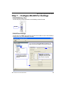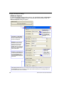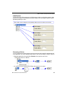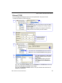
1
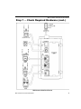
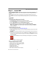
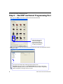
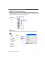
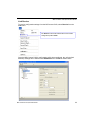
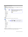
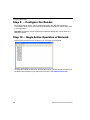
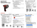
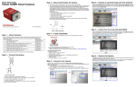
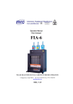
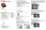
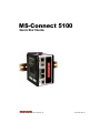
MS-Connect 5100
Quick Start Guide
Copyright ©2008 Microscan Systems, Inc.
83-215101 Rev B
Check Required Hardware
Step 1 — Check Required Hardware
Item
Description
Part Number
1
MS-Connect 5100 Enhanced Multidrop Concentrator
FIS-5100-0001G
2
Microscan Reader (one per Multidrop address)
FIS-XXXX-XXXXG
3
MS-Connect 5100 Power Supply (24VDC)
Reader Power Supply (24VDC; one required per reader)
97-100004-15
4
Programming Cable, USB, Type A to Type B, 6 ft.
61-000112-01
5
RS-232 Host Cable, 9-pin to RJ12, 6 ft.
61-000108-01
6
MS-Connect 5100 Concentrator Cable, 25-pin to RJ45, 10ft., gender changer
61-000113-01
7
IC-332 Adapter (5-volt readers only)
FIS-0001-0035G
8
IB-131 Interface Box
99-000018-01
9
IB-150 Kit, with reader cable, 6 ft.
98-000040-02
10
Multidrop Cable, 10 ft. (Gender changer required to connect IB-131 and IB-150)
61-100030-03
11
Object Detector (optional)
99-000017-01
Multidrop Network Hardware
Note: The Multidrop configuration shown above is just one example of configuration options. Any
combination of Microscan readers and interface boxes can be used in the Multidrop network. See
Step 6, Run ESP and Select Programming Port, for more specific information about the cabling
for each MS-Connect 5100 port.
2
MS-Connect 5100 Quick Start Guide
MS-Connect 5100 Quick Start Guide
Step 1 — Check Required Hardware (cont.)
MS-Connect 5100 Port Pinouts
MS-Connect 5100 Quick Start Guide
3
Install the MS-Connect 5100 Unit
Step 2 — Install the MS-Connect 5100 Unit
Mount the MS-Connect 5100 to a DIN Rail
The DIN rail should be positioned horizontally so that the unit’s ventilation holes are vertical
in relation to cabinet orientation.
Attach the MS-Connect 5100 to the DIN rail as shown below.
The clamps at the back of
the unit should snap
securely onto the DIN rail.
1
1.00” min. clearance
2
DIN rail
Note: A minimum clearance of 1 inch
(25.4 mm) should be maintained above
and below the unit in order to ensure
proper thermal regulation.
DIN rail
1.00” min. clearance
4
3
MS-Connect 5100 Quick Start Guide
MS-Connect 5100 Quick Start Guide
Step 3 — Connect Hardware for Multidrop
Power Connection Wiring
Once the MS-Connect 5100 unit has been physically installed in your application, the
power supply can be wired to the unit.
The Microscan power supply (97-100004-15) comes with a standard Micro-Change connector.
You must remove the Micro-Change connector from the end of the cable and wire the cable
directly to the screw terminal block at the top of the unit.
1
Remove the Micro-Change connector and wire-strip the power supply cable.
2
• Pin 1 = GND (black)
• Pin 2 = Shield
• Pin 3 = +24VDC (white)
1
2
3
Multidrop Hardware Configuration
The MS-Connect 5100 can support up to 32 Microscan readers in Multidrop configuration.
Important: All readers must be configured for Multidrop before they can be added to the
Multidrop network.
Use the RS-485 port for
the Multidrop network.
Note: The Multidrop configuration shown above is just one example of configuration options.
Any combination of Microscan readers and interface boxes can be used in the Multidrop network.
See Step 6, Run ESP and Select Programming Port, for specific information about the uses
of each MS-Connect 5100 port.
MS-Connect 5100 Quick Start Guide
5
Apply Power to the Multidrop Network
Step 4 — Apply Power to the Multidrop Network
Once you have configured your hardware for Multidrop and securely connected all other
cabling, you can safely apply power to the MS-Connect 5100 and the connected readers.
CAUTION: Be sure that all cables are connected BEFORE applying power to the
system. Always power down BEFORE disconnecting any cables.
Important Notes
It is very important that the power supply is mounted correctly if the unit is to operate reliably.
Please be sure to observe the following points:
• The power supply must be mounted close to the unit, with no more than 6 feet (1.8 m) of
cable between the supply and the unit. Ideally, the shortest length possible should be
used.
• The wire used to connect the unit’s power supply should be at least 22-gauge wire. If a
longer cable run is used, a heavier gauge wire should be used. The routing of the cable
should be kept away from large contactors, inverters, and other devices which may
generate significant electrical interference.
• A power supply with a Class 2 or SELV rating must be used. A Class 2 or SELV power
supply provides isolation to accessible circuits from hazardous voltage levels generated
by a mains power supply due to single faults. SELV is an acronym for “safety extra-low
voltage”. Safety extra-low voltage circuits shall exhibit voltages safe to touch both under
normal operating conditions and after a single fault, such as a breakdown of a layer of
basic insulation or after the failure of a single component has occurred.
6
MS-Connect 5100 Quick Start Guide
MS-Connect 5100 Quick Start Guide
Step 5 — Install ESP
Easy Setup Program (ESP) is Microscan’s proprietary setup and testing application. The
purpose of ESP is to provide a quick and easy way to set up and configure Microscan
products.
When the MS-Connect 5100 is connected to a host computer (Windows Vista, XP, or
2000), ESP can be used to configure Multidrop settings and set up communication with a
host.
Install ESP
If installing from a Microscan Tools CD:
1.
2.
3.
4.
Insert the Microscan Tools CD in your computer’s CD drive.
Select ESP Software from the navigation bar at the left of the screen.
Click on ESP Software under the Current Version heading.
Click the Run button and follow the prompts in the ESP Setup Wizard.
Note: During installation, you may see an Internet Explorer Security Warning that
states: “The publisher could not be verified.” If you see this warning, click Run to
continue installation.
If downloading from the web:
1. Go to the Download Center at www.microscan.com.
2. Create a new member account or, if you are already a member, enter your user name
and password.
3. Navigate to the “Microscan Software” section of the Download Center (near the top of
the page).
4. Click on the link showing the latest version of ESP. Extract the ESP installation files to
a location of your choice on the host computer. Note where your ESP.exe file is stored
on your hard drive.
5. At the end of the installation process, the following icon will appear on your desktop:
6. Click the ESP icon to start the program.
System Requirements for ESP
•
•
•
•
•
•
166 MHz Pentium processor (recommended)
Windows Vista, XP, or 2000 operating system
Internet Explorer 5.0 or higher
64 MB minimum RAM
40 MB minimum disk space
800 x 600 pixel minimum 256 color display
MS-Connect 5100 Quick Start Guide
7
Run ESP and Select Programming Port
Step 6 — Run ESP and Select Programming Port
When you run ESP, you will see a model menu that looks like this:
Select the MS-Connect
5100 and click OK, or
simply double-click the
MS-Connect 5100 button
to make your selection.
Note: The first time you select the MS-Connect 5100, the main view may take several
seconds to load.
You will see this window after selecting the MS-Connect 5100.
Important: Each port is shown in the Communications tree control, and must be
configured separately. When you click on the name of a port, that port’s configuration
options will appear to the right of the tree control.
8
MS-Connect 5100 Quick Start Guide
MS-Connect 5100 Quick Start Guide
USB and RS-232 Programming Ports
The MS-Connect 5100 can be programmed via the USB port or the RS-232/PG port. The
USB programming port allows you to send configuration settings to the MS-Connect 5100
via a standard USB connection. The RS-232 programming port allows you to send configuration
settings to the MS-Connect 5100 via a serial connection.
RS-232/PG
USB/PG
Link Options
To select a programming port, click on Link in the menu toolbar, and select Options.
Select the
appropriate
programming
port and click
OK.
MS-Connect 5100 Quick Start Guide
9
Run ESP and Select Programming Port
If using the USB programming port...
The first time you connect to the MS-Connect 5100 via USB, you will be prompted to install
USB drivers on the host computer. This operation will require administrative permissions.
Log in and select “Install from Specific Location” on the “Found New Hardware” Wizard,
then follow the prompts to locate and install drivers.
Note: When ESP is installed, the MS-Connect 5100 USB drivers are automatically placed
on the host hard drive along with ESP installation files.
Example Location: “C:\Program Files\Microscan\ESP-5100\Device”.
10
MS-Connect 5100 Quick Start Guide
MS-Connect 5100 Quick Start Guide
Link Receive
To receive configuration settings from the MS-Connect 5100, select Receive from the
Link menu.
The Receive function will load the MS-Connect 5100’s
configuration profile in ESP.
Once the MS-Connect 5100’s configuration profile has transferred, the unit’s default
Multidrop settings will be loaded to the RS-485 Port view in ESP as shown below.
MS-Connect 5100 Quick Start Guide
11
Run ESP and Select Programming Port
Update
When you make new configuration changes, you can use the Update command to activate
only those changes in the MS-Connect 5100.
Update sends only the most recently changed configuration
parameters to the MS-Connect 5100.
The F9 key can also be used to send the Update command,
as well as this icon in the toolbar:
Send
The Send command transfers all settings to the MS-Connect 5100.
Send transfers all current configuration settings to the
MS-Connect 5100.
Shift+F9 can also be used to initiate the Send command.
Important: Use the Send Time function to match the time and date in the MS-Connect
5100 with the time and date of the host computer sending commands.
12
MS-Connect 5100 Quick Start Guide
MS-Connect 5100 Quick Start Guide
Step 7 — Configure RS-485 Port Settings
RS-485 Multidrop Port
The RS-485 port polls the addresses on the Multidrop network for data.
RS-485
RS-485 Port Settings
The RS-485 view in ESP is automatically populated with the MS-Connect 5100’s Multidrop
settings when you use the Receive command.
You must set the desired Host Port for Multidrop poll
data to be sent from the MS-Connect 5100 to the host.
Readers can be added to
the Multidrop network by
clicking Add Additional
Device.
MS-Connect 5100 Quick Start Guide
Important: RS-485 Port
Settings must match reader
settings for baud rate, data
bits, stop bits, and parity.
13
Configure RS-485 Port Settings
Additional Options
For additional RS-485 communications options, click the Click for more configuration...
button in the Additional Options section of the RS-485 communications view. The
Additional Options dialog will appear.
Time Stamp and Date Stamp
allow you to append the time
and date to symbol data that is
decoded and displayed.
Separator lets you determine
the ASCII character that will
separate the time and date
stamps from symbol data.
Location allows you to determine
whether you want the time and
date stamps to appear before
or after symbol data.
Preamble and Postamble allow
you to set the ASCII character(s)
or control characters (such as
^M for Carriage Return) that will
precede and follow the displayed
symbol data.
Host Protocol
defines the type of
connection to the host.
LRC Enabled lets you
turn Longitudinal
Redundancy Check
on or off.
Include Address
allows you to
append the
reader’s Multidrop
address to the
beginning of each
reader’s data output.
Intercharacter Timeout allows you to set the amount of time that must pass before the end of a read cycle.
Line Terminator is the end-of-message character that must be sent at the end of a message stream to or
from the MS-Connect 5100 or host device.
14
MS-Connect 5100 Quick Start Guide
MS-Connect 5100 Quick Start Guide
Add Devices
The MS-Connect 5100 supports up to 32 Microscan readers in a Multidrop network. After
all devices (readers) in the network have been added, you must assign a station number
(Multidrop address) to each.
Each reader must be assigned its own Multidrop address when it is added to the network.
Renaming a Device
You can rename each device shown in the tree control to reflect specific characteristics of
your application, as in the example shown below. There are two ways to rename a device:
• Right-click the device icon and select Rename, then type the new name.
• Or, select the device and press the F2 key, then type the new name.
MS-Connect 5100 Quick Start Guide
15
Adjust Host Port Settings
Step 8 — Adjust Host Port Settings
RS-232
You must adjust the RS-232 host port to send polled data in the proper format.
To adjust the RS-232 host port:
Select the RS-232 port in the tree
control, and then click the Edit button
in the Driver Selection dialog.
Select Raw Serial
Port when the
Driver Picker for
Serial Port
appears, and click
OK.
Important: RS-232 Port Settings must match
host settings for baud rate, data bits, stop bits,
and parity.
16
MS-Connect 5100 Quick Start Guide
MS-Connect 5100 Quick Start Guide
Ethernet TCP/IP
You must adjust the Ethernet host port to send polled data in the proper format.
To adjust the Ethernet TCP/IP host port:
1
Select Ethernet in the tree control and then select Port Mode.
Manual Configuration: Port settings are manually configured
as shown below.
DHCP or APIPA: Port settings are configured automatically.
Identify the MS-Connect 5100 by the MAC address.
2
Enter the IP Address,
Network Mask, and
Gateway Address.
3
Then select one of the Protocol options and click the
Edit button when the Driver Selection dialog appears.
Select Raw TCP/IP Active or Raw TCP/IP
Passive to determine how the connection
is established.
Note: In Active, the MS-Connect 5100
establishes a connection with the host,
and in Passive, the host establishes the
connection.
4
If you are using Active TCP/IP, enter the IP Address and TCP/IP Port of the host
before saving changes to the MS-Connect 5100.
If you are using Passive TCP/IP, enter the TCP port number where the host will
establish its connection.
MS-Connect 5100 Quick Start Guide
17
Configure the Reader
Step 9 — Configure the Reader
Every application is unique, and each Microscan reader has different configuration
requirements. Refer to the user’s manual for the Microscan reader or readers being used
in your application.
Important: All readers must be configured for Multidrop before they can be added to a
Multidrop network.
Step 10 — Begin Active Operation of Network
Once all ports and devices are configured, you can begin capturing data.
For information about the Microscan products that can be used with the MS-Connect 5100,
consult the documentation on your Microscan Tools CD or visit www.microscan.com.
18
MS-Connect 5100 Quick Start Guide