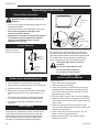
1
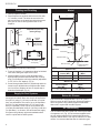
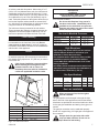
Rear Direct Vent
Model: DVHVAC36
INSTALLER/CONSUMER
SAFETY INFORMATION
PLEASE READ THIS MANUAL
BEFORE INSTALLING AND USING
APPLIANCE
WARNING!
IF THE INFORMATION IN THIS
MANUAL IS NOT FOLLOWED
EXACTLY, A FIRE OR EXPLOSION
MAY RESULT CAUSING PROPERTY
DAMAGE, PERSONAL INJURY OR
LOSS OF LIFE.
FOR YOUR SAFETY
Installation and service must be
performed by a qualified installer,
service agency or the gas supplier.
WHAT TO DO IF YOU SMELL GAS:
• Do not try to light any appliance.
• Do not touch any electric switch; do
not use any phone in your
building.
• Immediately call your gas supplier
from your neighbor's phone. Follow
the gas suppliers instructions.
• If you cannot reach your gas supplier
call the fire department.
Homeowner's Installation
and Operating Manual
DE S I GN
CERTIFIED
DO NOT STORE OR USE
GASOLINE OR OTHER
FLAMMABLE VAPORS AND
LIQUIDS IN THE VICINITY OF THIS
OR ANY OTHER APPLIANCE.
CE
RTIFI E D
INSTALLER: Leave this manual with the appliance.
CONSUMER: Retain this manual for future reference.
10001195 1/07 Rev. 5
DVHVAC36
Table of Contents
PLEASE READ THE INSTALLATION & OPERATING INSTRUCTIONS BEFORE USING APPLIANCE.
Thank you and congratulations on your purchase of a CFM Corporation fireplace.
IMPORTANT: Read all instructions and warnings carefully before starting installation. Failure to follow these
instructions may result in a possible fire hazard and will void the warranty.
Installation & Operating Instructions
Important Instructions ..........................................................................................................................3
Fireplace Dimensions ..........................................................................................................................4
Locating Your Fireplace .......................................................................................................................5
Clearance to Combustibles .................................................................................................................5
Unit Assembly ......................................................................................................................................5
Framing and Finishing .........................................................................................................................6
Supply Air Duct Systems .....................................................................................................................6
Mantel .............................................................................................................................................6
Return Air Plenum ...............................................................................................................................6
Air Conditioning ...................................................................................................................................6
Final Finishing .....................................................................................................................................7
Hearth .............................................................................................................................................7
Gas Inlet and Manifold Pressures .......................................................................................................7
High Elevations....................................................................................................................................7
Gas Specifications ...............................................................................................................................7
Gas Line Installation ............................................................................................................................7
Electrical Specifications .......................................................................................................................8
Electrical .............................................................................................................................................9
General Venting Information
General Venting ..................................................................................................................................9
General Venting Information - Termination Location .........................................................................10
General Information Assembling Vent Pipes ..................................................................................... 11
Twist Lock Pipes ................................................................................................................................11
How to Use the Vent Graph ...............................................................................................................12
Sidewall Venting Graph .....................................................................................................................12
Corner Installation .............................................................................................................................12
Rear Wall Venting Applications & Installation ....................................................................................12
Vertical Sidewall Applications & Installation.......................................................................................13
Below Grade Installation....................................................................................................................16
Vertical Through-the-Roof Applications & Installation ........................................................................17
Twist Lock Venting Components .......................................................................................................19
Operating Instructions
General Glass Information.................................................................................................................20
Louvre Removal ................................................................................................................................20
Window Frame Assembly Removal ...................................................................................................20
Glass Cleaning ..................................................................................................................................20
Installation of Logs, Lava Rock & Ember Material .............................................................................21
Setting Temperature Rise ..................................................................................................................21
Lava Rock..........................................................................................................................................21
Flame Adjustment ..............................................................................................................................21
Emergency Heat ................................................................................................................................21
Flame Characteristics ........................................................................................................................21
Inspecting the Venting System ..........................................................................................................22
Inspecting the Venting/Heating Exchange System ............................................................................22
Ceramic Refractory Installation .........................................................................................................22
Lighting and Operating Instructions ...................................................................................................23
Troubleshooting .................................................................................................................................24
Maintenance
Cleaning the Standing Pilot Control System......................................................................................25
Replacement Parts .......................................................................................................................................26
Optional Accessories
Decorative Bay Window ....................................................................................................................28
Warranty ........................................................................................................................................................29
Energuide ......................................................................................................................................................30
2
10001195
DVHVAC36
Installation & Operating Instructions
This gas fireplace should be installed by a qualified
installer in accordance with local building codes and with
current CSA-B149.1 Installation codes for Gas Burning
Fireplaces and Equipment. For U.S.A Installations follow
local codes and/or the current National Fuel Gas Code.
ANSI Z223.1/NFPA 54.
In the Commonwealth of Massachusetts, all gas fitting
and installation of this heater shall only be done by a
licensed gas fitter or licensed plumber.
FOR SAFE INSTALLATION AND OPERATION PLEASE
NOTE THE FOLLOWING:
1. This fireplace gives off high temperatures and should
be located out of high traffic areas and away from
furniture and draperies.
2. Children and adults should be alerted to the hazards
of the high surface temperatures of this fireplace and
should stay away to avoid burns or ignition of clothing.
3. Children should be carefully supervised when they are
in the same room as your fireplace.
4. Under no circumstances should this fireplace be modified. Parts removed for servicing should be replaced
prior to operating this fireplace again.
5. Installation and any repairs to this fireplace should
be carried out by a qualified service person. A professional service person should be contacted to inspect
this fireplace annually. Make it a practice to have all of
your gas fireplaces checked annually. More frequent
cleaning may be required due to excess lint and dust
from carpeting, bedding material, etc.
6. Control compartments, burners and air passages in
this fireplace should be kept clean and free of dust
and lint. Make sure that the gas valve and pilot light
are turned off before you attempt to clean this fireplace.
7. The venting system (chimney) of this fireplace should
be checked at least once a year and if needed your
venting system should be cleaned.
8. Keep the area around your fireplace clear of combustible materials, gasoline and other flammable vapor and
liquids. This fireplace should not be used as a drying
rack for clothing, nor should Christmas stockings or
decorations be hung in the area of it.
9. Under no circumstances should any solid fuels (wood,
coal, paper or cardboard etc.) be used in this fireplace.
10. The flow of combustion and ventilation air must not
be obstructed in any way.
11. Whether the fireplace is installed directly on
carpeting, vinyl tile or any combustible material other
than wood, this fireplace must be installed on a metal
or wood panel extending the full width and depth of
the fireplace.
10001195
12. This fireplace requires adequate ventilation and
combustion air to operate properly.
13. The unit must be adjusted to obtain a temperature
rise of 25-55°F, at maximum input rate.
14. The fireplace must be electrically grounded in
accordance with local codes. In the United States,
all electrical and grounding must also conform to the
current National Electric Code, ANSI/NFPA No. 70. In
Canada, all electrical and grounding for the unit must
also conform to the current Canadian Electrical Code
Part 1, CSA Standard C22.1
15. Field wiring to the appliance must meet or exceed
the specifications for type T wire and must withstand a
minimum of 180°F temperature rise.
16. Service access must be provided for the service and
replacement of the blower motor, air filter etc. The use
of CFM Corporation mantels designed for this product
is recommended.
IMPORTANT:
PLEASE REVIEW THE FOLLOWING CAREFULLY
It is normal for fireplaces fabricated of steel to give off
some expansion and/or contraction noises during the
start up or cool down cycle. Similar noises are found
with your furnace heat exchanger or car engine.
It is not unusual for your CFM Corporation gas
fireplace to give off some odor the first time it is
burned. This is due to the curing of the paint and any
undetected oil from the manufacturing process.
Please ensure that your room is well ventilated - open
all windows.
It is recommended that you burn your fireplace for at
least ten (10) hours the first time you use it.
The appliance may be installed in an aftermarket
permanently located, manufactured (mobile) home,
where not prohibited by local codes.
This appliance is only for use with the type of gas
indicated on the rating plate. This appliance is not
convertible for use with other gases unless a certified kit is used.
Proposition 65 Warning: Fuels used in gas, woodburning or oil fired appliances, and the products of
combustion of such fuels, contain chemicals known to
the State of California to cause cancer, birth defects
and other reproductive harm.
California Health & Safety Code Sec. 25249.6
3
DVHVAC36
Fireplace Dimensions
U
L
V
Z
V
G
H
W
E
F
T
X
I
K
B
C
J
P
O
N
D
A
S
Q
R
M
L
Fig. 2 Fireplace specifications.
Ref.
A
B
C
D
E
F
G
H
I
J
K
L
M
4
DVHVAC36
36"
(914 mm)
34¹⁄₄" (870 mm)
21"
(533 mm)
33"
(838 mm)
63⁵¹⁄₆₄" (1621 mm)
70"
(1780 mm)
16⁵⁄₃₂" (410 mm)
21⁵⁄₃₂" (537 mm)
38³⁄₁₆" (970 mm)
28¹⁵⁄₁₆" (735 mm)
33¹⁄₂" (851 mm)
18³⁄₁₆" (462 mm)
13²¹⁄₃₂" (347 mm)
1195Ref.
N
DVHVAC
O
Specs
P djt
8/20/03
Q
R
S
T
U
V
W
X
Y
Z
DVHVAC36
9⁵⁄₈"
(245 mm)
6⁷⁄₈"
(175 mm)
2⁹⁄₃₂"
(58 mm)
2"
(51 mm)
3¹³⁄₁₆" (97 mm)
4"
(102 mm)
1/2"
(13 mm)
18"
(457 mm)
16⁷⁄₂₁" (412 mm)
83¹⁄₈" (2111 mm)
5³⁄₈"
(136 mm)
58³⁄₄" (1493 mm)
41⁹⁄₁₆" (1056 mm)
10001195
DVHVAC36
Locating Your Gas Fireplace
Y
E
B
A
C
Y
X
D
X
F
LU584-3
Fig. 1 Locate gas fireplace.
A) Flat on wall
D) *Room divider
Y) 6" minimum
B) Cross corner
E) *Flat on wall corner
C) **Island
F) Chase installation
LU584-3
NOTE (Fig. 1): locating unit
** Island (C) and DVHVAC
Room Divider (D) installation is possible as
8/19/03
long as the horizontal
portion of the vent system (X) does not
exceed 20' (6m). See details in Venting Section.
* When you install your CFM Corporation fireplace in (D) Room
divider or (E) Flat on wall corner positions (Y), a minimum of 6"
(153mm) clearance must be maintained from the perpendicular
wall and the front of the fireplace.
Clearance to Combustibles
5. Attach the metal conduit from the fireplace cabinet
to the 7/8" diameter hole in the side of the air circulating blower section using the nut provided. Do
not feed the two yellow wires which are outside the
conduit through the hole. Insert the terminal on the
white wire (common) into position 1 on the jack plug.
Insert the terminal on the black wire (cooling speed)
into position 2 on the jack plug. Insert the terminal on
the red wire (heating speed), into position 3, 4 or 5
on the jack plug. If unsure, select position 4 on the
jack plug for heating speed and adjust if necessary.
If desired the speed selections can be changed later.
Refer to Figure 8 Wiring Diagram.
WARNING: Ensure that all three wires are properly
inserted into jack plug, even if an optional air conditioner is not to be used.
6. Reinstall jack plug into motor and replace access
panel.
7. Place the coil cabinet section onto the right side of
the fireplace cabinet so the access panel faces the
front of the unit. (Fig. 3) Remove the access panel
and secure the coil cabinet to the fireplace cabinet
using 8 of the #8 screws provided.
8. Connect the 1/4" quick connect terminals of the two
yellow wires from the fireplace cabinet to the high
limit safety control located on the top of the coil cabinet.
Blower Section
Back .............................................................. 0" (0 mm)
Side ............................................................... 0" (0 mm)
Floor .............................................................. 0" (0 mm)
Top ................................................................ 0" (0 mm)
Flue ...................................................... 2" (51 mm) Top
..............................................1" (25 mm) Sides/Bottom
Coil Cabinet
Unit Assembly
The DVHVAC36 is shipped in three cartons. The first
carton contains the fireplace cabinet. The second carton contains the air circulating blower section and the
third carton contains the coil cabinet. Unpack all three
sections before following the assembly instructions:
1. Place the air circulating blower section onto the left
side of the fireplace cabinet. (Fig. 3)
2. Ensure the damper plate below the blower assembly
works freely without binding. Rotate it downwards
and ensure that it returns to a closed position.
3. Secure air circulating blower section to fireplace
cabinet using 8 of the #8 screws provided.
4. Remove the access panel on the front of the air circulating blower section by removing the #10-24 nuts.
Remove the jack plug from the air circulating blower
motor by gently depressing tab.
10001195
Fireplace Cabinet
FP1399
Fig. 3 DVHVAC36 unit assembly.
FP1399
DVHVAC
fireplace assy
8/20/03
5
DVHVAC36
Mantel
Framing and Finishing
1. Choose fireplace location.
2. Place fireplace into position and secure to floor with
1¹⁄₂" screws, or nails. The holes to secure the fireplace to the floor are located just behind the access
door grille on the left and right hand side of the
fireplace.
C
A
Adjustable Drywall Strip
(Nailing Flange)
D
B
B
Screw
Position
A
B
C
Drywall
Depth
1/2" (13 mm)
5/8" (16 mm)
3/4" (19 mm)
C
A
Top Louvre Opening
Side View
Front Glass
Electrical
KnockOut
Optional Hearth
Adjustable
1/2", 5/8" &
3/4" Spacing
Gas Knock-Out
Electrical Cable
Knock-Out
FP1023
Fig. 4 Adjustable drywall strip (nailing flange).
3. Frame in fireplace. It is important to allow for finished
face when setting the depth of the frame.
4. Attach fireplace to frame using adjustable frame
drywall strips (located behind access door for shipFP1023
ping). Preset depth to
suit facing material (adjustable
side nailing
to 1/2", 5/8" or 3/4" depths).
(Fig.flange
4)
1/27/00
djt
5. Screw through slotted holes in drywall strip and then
screw into pre-drilled holes on fireplace side. Measure from face of fireplace to face of drywall strip to
determine final depth. (Fig. 4)
Supply Air Duct Systems
The DVHVAC36 fireplace has three 6" (152 mm) diameter supply air outlets. Duct runs of up to 65 equivalent
feet (19.8 m) using 6" (152 mm) round duct (or equivalent), are permissible. Duct runs of up to 40 equivalent
feet (12.2 m) are permitted using 5" (127 mm) round
duct (or equivalent). Runs of up to 30 equivalent feet
(9 m) are permitted when using 4" (102 mm) round duct
(or equivalent). In all cases, size and install the supply
air system using industry approved standards which
result in a quiet and low static system.
6
FP1400
Mantel Chart
Ref.
A
B
From Top
Ref.
Louvre (Min.)
FP1400 C
15¹⁄₅" (394 mm)
DVHVAC
48" (1219 mm)
D
mantel setup
8/03
Depth
(Max.)
7" (178 mm)
any
Mantel Leg Chart
From Fireplace
Side (Min.)
7¹⁄₂" (191 mm)
Depth
(Max.)
1³⁄₄" (44 mm)
Fig. 5 Combustible mantel installation.
Return Air Plenum
The DVHVAC36 is equipped with a 16" x 16" (256 x
256 mm) return air duct connection. Size and install the
return air system using industry approved standards
that result in a quiet and low static system.
Air Conditioning
The coil cabinet has been sized to fit most major brands
of evaporator coil. (Fig. 6) The brackets supplied inside
the coil cabinet represent the lowest height above the
fireplace cabinet that the coil may be mounted. For best
results, it is recommended that low air restriction types
10001195
DVHVAC36
of coils be used with this product. When using 4" or 5"
(102 or 127 mm) diameter duct work, the maximum air
conditioning system size should be limited to 1.5 tons
(18,000 BtuH). When using 6" (152 mm) diameter duct,
air conditioners of up to 2 tons (24,000 BtuH) may be
used. Total static pressure of the system above the outlet from the fireplace cabinet should not exceed 0.40"
w.c. with the air circulating blower on high speed, when
using the maximum air conditioning capacity.
Two rails come factory mounted in the coil cabinet.
These represent the minimum clearance between the
evaporator coil and the fireplace cabinet top. Do not
mount an evaporator coil below the level of the rails.
Final Finishing
Noncombustible materials such as brick and tile can
be extended over the front face of the unit (Do not
cover louvres or glass door). If a trim kit is going to
be installed, brick and tile will have to be installed flush
with the side of this appliance.
Hearth
A hearth is not mandatory, however it is recommended
for aesthetic purposes. We recommend a noncombustible hearth which projects out 12" (305 mm) or more in
front of this unit.
Cold climate installation recommendation:
When installing this unit against a noninsulated exterior wall or chase, it is
mandatory the outer walls be insulated to
conform to applicable insulation codes.
DVHVAC36
Certified to
ANSI Z21.88-2005 / CSA 2.33-2005
Vented Gas Fireplace Heaters
Unit: B12AC0, B12BC0
Do not use this fireplace if any part of it
has been under water. Immediately call a
qualified service technician to inspect the
fireplace and replace any part of the control
which has been under water.
Gas Inlet & Manifold Pressures
Supply Pressure
Minimum
Maximum
Manifold Pressure
Natural
5.5" w.c.
14.0" w.c.
3.5" w.c.
LP (Propane)
11.0" w.c.
14.0" w.c.
10.0" w.c.
High Elevations
Input ratings are shown in BTU per hour and are
certified without deration for elevations up to
4,500 feet (1,370 m) above sea level.
For elevations above 4,500 feet (1,370 m) in USA,
installations must be in accordance with the
current ANSI Z223.1/NFPA 54 and/or local codes
having jurisdiction.
In Canada, please consult provincial and/or local
authorities having jurisdiction for installations at
elevations above 4,500 feet (1,370 m).
Gas Specifications
E
Model
Fuel
Gas Control
Max.
Input
BTUH
DVHVAC36RN
DVHVAC36RP
Natural Gas
Propane Gas
Millivolt HI/LO
Millivolt HI/LO
40,000
40,000
Min.
Input
BTUH
25,000
25,000
D
Gas Line Installation
When purging gas line, the front glass
must be removed.
C
A
Ref.
A
B
C
D
E
Rails
B
Dimension
21"
(534 mm)
17⁷⁄₁₇" (443 mm)
3⁷⁄₁₆" FP1401
(88 mm)
DVHVAC
20⁷⁄₁₆" coil(519 mm)
8¹⁄₂" 8/03
(217 mm)
Fig. 6 Coil cabinet dimensions.
10001195
FP1401
The gas pipeline can be brought in through the right
side or left side of the appliance as well as the bottom.
Knockouts are provided at convenient locations to allow
for the gas pipe installation and testing of any gas connection.
The gas line connection can be made with properly
tinned 3/8" copper tubing, 3/8" rigid pipe or an approved
flex connector.
Always check for gas leaks with a mild
soap and water solution. Do not use an
open flame for leak testing.
7
DVHVAC36
The gas control is equipped with a captured screw type
pressure test point, therefore it is not necessary to provide a 1/8" test point up stream of the control.
1/2" Gas Supply
1/2" NPT x 1/2" Flare
Shut-off Valve
3/8" Flex Line
(From Valve)
When using copper or flex connector use only approved
fittings. When using black iron pipe always provide a
union so the gas line can be easily disconnected for
burner or fan servicing. (Fig. 7) Refer to gas specifications for pressure details and ratings.
The fireplace valve must not be subjected to any test
pressures exceeding 1/2 psi. Isolate or disconnect this
or any other gas appliance control from the gas line
when pressure testing.
FP297a
Fig. 7 Typical gas supply installation.
Electrical Specifications
120V AC
60Hz
Less than 12 Amps
1/3 Horsepower
8
FP297A
INSTA VENT FREE
UVHB26 GAS SUPPLY
7/1/98
10001195
DVHVAC36
Electrical
5. Electrically ground the unit in accordance with
local codes, or in the absence of local codes in
accordance with the Canadian Electrical Code, Part
1 (CSA Standard C22.1) in Canada, or with the
National Electric Code (ANSI/NFPA No. 70) in the
United States.
6. The circuit board is equipped with two (2) accessory
terminals. The terminal marked "Air Cleaner" and
"Humidifier" are rated for 120V 0.5 Amps and are
energized with the air circulating blower. Connect the
neutral leg of the accessory to the 120V neutral wire.
EMERGENCY
HEAT
SWITCH
TH
RED
WHITE
12 YELLOW
ACB
4 RED
5 WHITE
G
18 GRAY
Y
19 YELLOW
GND
LOW
NOT USED
MED-HI
MED-LO
BROWN
TH
3
4
5
6
TH-PILE +
TP
24 VAC HOT
24 VAC RTN
2
HUMIDIFIER
2 RED
ACB HEAT
3 BLACK
ACB COOL
AIR CLEANER
20 GREEN
XFORMER 1
9 YELLOW
HUMID RTN
10 VAC RTN
ACB RTN
SOLENOID 2
X FORMER 2
110 VAC HOT
SOLENOID 1
5
R
W1
1
CLEAN RTN
4
THERMOSTAT
3
CHASSIS GND
11 GREEN
ORANGE/BLACK
ORANGE
17 GREEN
TP/TH
10 BLUE
NOT USED
16 YELLOW
LIMIT
1
FLAME
ADJUST
13 BLUE
COMMON
TP
15 BLUE
TP/TH
14 YELLOW
GAS VALVE
TH TP-PILE +
THERMOPILE
Refer to Figure 8 for field wiring.
1. Select fuse and wire size according to rating plate
amperage.
2. Install a separate fused disconnect switch near the
unit for service purposes.
3. Knockouts are provided on both sides of cabinet for
electrical wiring.
4. Install room thermostat (24 volt) according to
instructions provided with thermostat, using 18
gauge wire or larger.
6 BLACK
1 WHITE
7 WHITE
8 BLUE
8 BLUE
110 VAC HOT
L1
110 VAC RTN
L2
GREEN
FP1413
Fig. 8 DVHVAC36 wiring diagram.
General Venting
This model is approved to be vented either through the
side wall, or vertically through the roof.
24" (610 mm) from the front of the termination hood.
Do not locate termination hood where excessive snow
• Only venting components specifically approved andFP1413or ice build up may occur. Be sure to check vent termination area after snow falls, and clear to prevent aclabelled for this fireplace may be used.
DVHVAC36
cidental blockage of venting system. When using snow
• Minimum clearances between vent pipes and comblowers, make sure snow is not directed towards vent
wiring diagram
bustible materials is 1" (25 mm).
termination area.
• Venting terminals shall not be recessed into a wall or11/03
Location of Vent Termination
siding.
It is imperative that the vent termination be located ob• Horizontal venting must be installed on a level plane
serving the minimum clearances as shown on Page 10.
without an inclining or declining slope.
*Check with local codes or in absence of same with
There must not be any obstruction such as bushes,
CSA B149.1 Installation Codes (1991) for Canada or for
garden sheds, fences, decks or utility buildings within
U.S.A. Installations follow the current National Fuel Gas
Code, ANSI Z223.1/NFPA 54.
10001195
9
DVHVAC36
General Venting Information - Termination Location
INSIDE
CORNER DETAIL
G
V
H
A
N
N
D
L
V
E
C
B
V
F
B
�����
������
Ope
rable
V
B
Operable
B
V
V
Fixed
Closed
B
J
X
X AIR SUPPLY INLET
M
I
A
CFM145a
V VENT TERMINATION
B
V
C = Clearance to permanently closed window
D = Vertical clearance to ventilated soffit located
above the terminal within a horizontal
distance of 2 feet (610mm) from the center
line of the terminal
E = Clearance to unventilated soffit
F = Clearance to outside corner
G = Clearance to inside corner (see next page)
H = Clearance to each inside of center line
extended above meter/regulator assembly
I = Clearance to service regulator vent outlet
J = Clearance to nonmechanical air supply inlet
to building or the combustion air inlet to any
other appliances
K = Clearance to a mechanical air supply inlet
K
X
AREA WHERE TERMINAL IS NOT PERMITTED
Canadian Installations1
A = Clearance above grade, veranda, porch,
deck, or balcony
B = Clearance to window or door that may be
opened
V
CFM145a
12”
(30cm)
DV Termin Location
5/01/01 Rev. 12/05/01
sta
6” (15cm) for appliances
< 10,000Btuh (3kW), 12” (30cm)
for appliances > 10,000 Btuh (3kW) and
< 100,000 Btuh (30kW), 36” (91cm)
for appliances > 100,000 Btuh (30kW)
US Installations2
12” (30cm)
12” (305mm) recommended to
prevent window condensation
6” (15cm) for appliances
< 10,000 Btuh (3kW), 9”
(23cm) for appliances > 10,000
Btuh (3kW) and < 50,000 Btuh
(15kW), 12” (30cm) for
appliances > 50,000 Btuh (15kW)
12” (305mm) recommended to
prevent window condensation
18” (458mm)
18” (458mm)
12” (305mm)
see next page
see next page
3’ (91cm) within a height of 15’
above the meter/regulator assembly
3’ (91cm)
6” (15cm) for appliances < 10,000
Btuh (3kW), 12” (30cm) for
appliances > 10,000 Btuh (3kW) and <
100,000 Btuh (30kW), 36” (91cm)
for appliances > 100,000 Btuh (30kW)
12” (305mm)
see next page
see next page
3’ (91cm) within a height of 15’
above the meter/regulator assy
3’ (91cm)
6” (15cm) for appliances
< 10,000 Btuh (3kW), 9”
(23cm) for appliances > 10,000
Btuh (3kW) and < 50,000 Btuh
(15kW), 12” (30cm) for
appliances > 50,000 Btuh (15kW)
3’ (91cm) above if within 10’
(3m) horizontally
7’ (2.13m)†
6’ (1.83m)
L = Clearance above paved sidewalk or paved 7’ (2.13m)†
driveway located on public property
M = Clearance under veranda, porch, deck or
12” (30cm)‡
12” (30cm)‡
balcony
N = Clearance above a roof shall extend a minimum of 24” (610mm) above the highest point when it passes through the roof
surface, and any other obstruction within a horizontal distance of 18” (450mm).
1 In accordance with the current CSA-B149 Installation Codes
2 In accordance with the current ANSI Z223.1/NFPA 54 National Fuel Gas Codes
† A vent shall not terminate directly above a sidewalk or paved driveway which is located between two single family dwellings and serves
both dwellings
‡ only permitted if veranda, porch, deck or balcony is fully open on a minimum 2 sides beneath the floor:
NOTE: 1. Local codes or regulations may require different clearances.
2. The special venting system used on Direct Vent fireplaces are certified as part of the appliance, with clearances tested and approved by the listing agency.
3. CFM Corporation assumes no responsibility for the improper performance of the appliance when the venting system does not
meet these requirements.
Fig. 9 Termination clearances.
10
10001195
DVHVAC36
Termination Clearances
Termination clearances for buildings with combustible and noncombustible exteriors.
Inside Corner
Alcove Applications*
Outside Corner
G=
Combustible
6" (152 mm)
G
F=
Combustible
6" (152 mm)
Noncombustible
2" (51 mm)
V
Noncombustible
2" (51 mm)
V
C
V
E
O
F
Balcony with perpendicular side wall
Balcony with no side wall
D
C
E = Min. 6” (152 mm) for
non-vinyl sidewalls
Min. 12” (305 mm) for
vinyl sidewalls
O = 8’ (2.4 m) Min.
M
M
V
V
P
M=
Combustible &
Noncombustible
12" (305 mm)
Combustible &
Noncombustible
M = 24" (610 mm)
P = 20” (508 mm)
No.
of Caps
1
2
3
4
DMin.
3’ (.9 mm)
6’ (1.8 m)
9’ (2.7 m)
12’ (3.7 m)
CMax.
2 x DActual
1 x DActual
2/3 x DActual
1/2 x DActual
DMin. = # of Termination caps x 3
CMax. = (2 / # termination caps) x DActual
584-15
*NOTE: Termination in an alcove space (spaces open only on one side and with an overhang) is permitted with the dimensions
specified for vinyl or non-vinyl siding and soffits. 1. There must be a 3’ (914 mm) minimum between termination caps. 2. All
mechanical air intakes within 10’ (1 m) of a termination cap must be a minimum of 3’ (914 mm) below the termination cap. 3. All
gravity air intakes within 3’ (914 mm) of a termination cap must be a minimum of 1’ (305 mm) below the termination cap.
Fig. 10 Termination clearances.
General Information Assembling Vent Pipes
Canadian Installations:
Venting system must be installed in accordance with the
current CSA-B149.1 installation code.
USA Installations:
The venting system must conform with local codes and/
or the current National Fuel Gas code ANSI Z223.1/
NFPA 54.
Only venting components manufactured by CFM Corporation can be used in Direct Vent systems.
Twist Lock Pipes
When using CFM Corporation twist-lock pipe it is not
necessary to use sealant on the joints. The only areas
of the venting system that need to be sealed with high
temperature silicone sealant are the collars on the
fireplace and termination, and the sliding joint of any
telescopic vent section used in the system.
To join the twist lock pipes together, simply align the
beads of the male end with the grooves of the female
end, then while bringing the pipe together, twist the pipe
until the flange on the female end contacts the external
flange on the male end. It is recommended that you
secure the joints with three (3) sheet metal screws,
however this is not mandatory with twist lock pipe. (Fig.
11)
To make it easier to assemble the joints we suggest
putting a lubricant (Vaseline or similar) on the male end
of the twist lock pipe prior to assembly.
Male End
Female End
Screw Holes
TWL100
Fig. 11 Twist-lock pipe joints.
10001195
11
TWL100
Twist Lock Pipe
3/12/99 djt
DVHVAC36
How to Use the Vent Graph
Corner Installation
1. Determine the height of the center of the horizontal
vent pipe exiting through the outer wall. Using this
dimension on the Sidewall Vent Graph (Fig. 12),
locate the point it intersects with the slanted graph
line.
2. From the point of this intersection, draw a vertical
line to the bottom of the graph.
3. Select the indicated dimension, and position the fireplace in accordance with same. (Refer to examples
Fig. 12)
When the DVHVAC36 unit is installed in a corner,
Figure 1, Option B, the vent configuration must follow the Vertical Sidewall Installation Instructions.
EXAMPLE A:
• Only CFM Corporation venting components are
If the vertical dimension from the floor of the unit is 11'
(3.4m) the horizontal run to the face of the outer wall
must not exceed 14' (4.3 m).
EXAMPLE B:
If the vertical dimension from the floor of the unit is 7'
(2m), the horizontal run to the face of the outer wall
must not exceed 8¹⁄₂' (2.6 m).
Rear Wall Venting Applications
This appliance may be vented directly to a termination
located on the rear wall behind the appliance.
NOTE: It is not necessary to seal the vent pipe joints for
any rear vent applications.
•
•
approved to be used in these applications. Refer to
“Venting Components” listed for different installation
requirements.
The maximum horizontal distance between the rear
of the appliance and the outside face of the rear wall
is 20” (508 mm). (Fig. 13)
Minimum clearances between vent pipe and combustible materials are as follows:
Sidewall Venting Graph
Top - 2” (51 mm)
Sides - 1” (25 mm)
Bottom - 1” (25 mm)
(Dimensions in Feet)
30
29
28
27
26
20"
(508mm)
25
23
22
21
20
19
18
17
16
15
14
13
eg: A
12
11
10
9
8
7
eg: B
6
Vertical dimension from the floor of the unit
to the center of the horizontal vent pipe
24
5
4
FP1403
Fig. 13 Rear vent application.
Rear Wall Installations
FP1403
STEP 1
DVHVAC
Locate vent opening
on wall. To locate hole center, refer
rear dimensions
vent app on Page 4.
to appropriate fireplace
Combustible Walls8/03
(Fig. 14): Cut a 10³⁄₈" x 9³⁄₈" (265 x
240 mm) hole through the exterior wall and frame as
shown.
Noncombustible Walls (Fig. 14): Hole opening must be
7¹⁄₂" (191 mm) in diameter.
STEP 2
3
3
4
5 6
7 8
9 10 11 12 13 14 15 16 17 18 19 20
Horizontal dimension from the outside face of the wall
to the center of the fireplace vent flange
CFM102
Fig. 12 Sidewall venting
graph. (Dimensions in feet)
DV Graphic
9/28/00 sta
12
Measure wall thickness and cut adjustable zero clearance sleeve parts to proper length (MAXIMUM 12" /
305 mm). Adjust sleeve to maximum (10³⁄₈" x 9³⁄₈" / 265
x 240 mm) and attach to firestop with #8 sheet metal
screws (supplied). (Fig. 15) Install firestop assembly.
10001195
DVHVAC36
STEP 4
Vent Opening for Combustible Wall
Slip 4" (102 mm) and 7" (178 mm) pipes onto respective flue collars. Make sure to fix to the fireplace collar
the 4" pipe with three (3) screws before fixing the 7"
pipe on the 7" collar. Both pipes must be on a level
plane. (Fig. 17)
9³⁄₈"
(240 mm)
Framing
Detail
10³⁄₈"
(265 mm)
STEP 5
Guide the vent termination 4" collar into the 4" pipe then
the 7" collar into the 7" pipe. Do not force the venting
into position. If the pipes do not line up with the termination collars, disassemble elbows or pipes and reattach
to the fireplace collar.
Fireplace
Hearth
Vent Opening for Noncombustible Wall
STEP 6
Recheck the fireplace to make sure it is levelled, properly positioned and nailed or screwed to the floor.
7¹⁄₂"
(190 mm)
VO584-100
Fig. 14 Locate vent opening on wall.
Adjustable
Zero Clearance
Sleeve
Max. Length
12" (305 mm)
Screws
VO584-100 #8
(2)
Vent Opening
2/99 djt
#8
If applied, the fireplace adjustable frame drywall strips
(nailing flanges) should be fastened. Refer to Framing
and Finishing.
Finished
Wall
Vent Termination
Screws
(2)
#8 Screws (2)
Firestop
Adjustable Zero Clearance Sleeve
ZCS101
ZCS101
Fig. 15 Adjustable zero clearance sleeve.
Zero Clearance Sleeve
STEP 3
3/11/99 djt
Fig. 17 Side view of final unit location.
Measure from fireplace collar face to face of outside
wall (add 2" (51 mm) for vent pipe overlap). Mark pipes
and cut to length. It is very important that the two pipes
are flush with the outside wall once the fireplace is in its
final location. (Fig. 16)
Zero Clearance Sleeve
FP1404
Fig. 16 Firestop and zero clearance sleeve in place.
10001195
FP1005
Vertical Sidewall
Applications
Side View Vent Termination
1/25/00
djt
Since it is very
important
that the venting system maintain its balance between
the combustion air intake and the flue
gas exhaust, certain limitations as to vent
configurations apply and must be strictly
adhered to.
The graph showing the relationship between vertical
and horizontal side wall venting will help to determine
the various vent lengths allowable. (Fig. 12)
Firestop
FP1404
DVHVAC
vent pipe
8/03
FP1005
Minimum clearance between vent pipes
and combustible materials is 1" (25 mm)
on top, bottom and sides unless otherwise
noted.
When vent termination exits through foundation less
than 20" (508 mm) below siding outcrop, the vent pipe
must flush up with the siding. A 7DVSS must also be
used.
13
DVHVAC36
It is always best to locate the fireplace in such a way
that minimizes the number of offsets and horizontal vent
length.
The horizontal vent run refers to the total length of vent
pipe from the flue collar of the fireplace to the face of
the outer wall.
Horizontal plane means no vertical rise exists on this
portion of the vent assembly.
•
Example: According to the vent chart the maximum
horizontal vent length is 20' (6 m) when the vertical
height is 7.5' (2.3 m) from fireplace base height. If
one (1) 90° elbow is required in the horizontal vent, it
must be reduced to 17' (5.2 m).
The maximum number of elbow degrees in a system is 270°. (This does not include transition elbow
from rear vent to vertical vent.) (Fig. 21)
For some installations, it may be desirable to have
some amount of the horizontal vent run immediately
after the fireplace. A vertical rise must be used but can
be located anywhere in the vent system, to meet the
parameters identified in the venting graph.
Maximum
3' (914mm)
• The maximum horizontal vent run is 20' (6 m) when
the vertical vent rise is 7¹⁄₂' (2.3 m). (Fig. 18)
Vertical Dimension 7¹⁄₂' (2.3m)
Minimum when
Horizontal Run is
20' (6m)
Maximum
20 ft. (6.1m)
12"
(305mm)
48"
(1.2m)
7TDVRT90
Elbow
15 ft.
(4.6m)
CFM142
Fig. 19 Maximum horizontal vent run with 90° elbows directly
off back of unit.
CFM142
Venting
2/2/01 sta
7.5'
(2.3m)
B
7'
(2.1m)
A
10'
(3m)
7TDVRT90
Elbow
CFM141
Fig. 18 Maximum number of 90° elbows is three.
A + B = 17' (5.2m) Max.
7' 6"
(2.3m)
CFM141
• The maximum number
of 90°
2/2/01
sta elbows per side wall
•
•
•
•
installation is three (3).
The maximum number of 45° elbows permitted per
side wall installation is two (2). These elbows can be
installed in either the vertical or horizontal run.
When one (1) 90° elbow is installed directly onto
another off the back of the fireplace the maximum
horizontal vent length is 36" (914 mm). (Fig. 19)
For each 45° elbow installed in the horizontal run
(while maintaining a constant horizontal plane), the
length of the horizontal run MUST be reduced by 18"
(457 mm). This does not apply if the 45° elbows are
installed on the vertical part of the vent system.
If a 90° elbow is used in the horizontal vent run
(level height maintained) the maximum horizontal
vent length is reduced by 36" (914 mm) (Fig. 20)
This does not apply if the 90° elbows are used to
increase or redirect a vertical rise.
CFM147
Fig. 20 Maximum vent run with elbows.
Sample:
V584-201
Elbow 1
Elbow 2
Elbow 3
Elbow 4
Total angular variation
4
Horizontal Run
=
90°
2/99 djt
= 45°
= 45°
= 90°
= 270°
o
1 + 2 + 3 + 4 = 270
1
2
3
CFM132
14
CFM132
Fig. 21 Maximum number of elbows.
Insert Rear Vent Sidewall
2/26/01 sta
10001195
DVHVAC36
• IMPORTANT • Minimum clearance between vent
STEP 2
pipes and combustible materials is 1" (25mm) on bottom, sides and top.
Measure wall thickness and cut adjustable zero clearance sleeve parts to proper length (MAXIMUM 12" /
305mm). (Fig. 23) Adjust sleeve to minimum (9³⁄₈" x 9³⁄₈"
/ 240 x 240 mm) and attach to firestop with #8 sheet
metal screws (supplied). Assemble sleeve and attach
to firestop with #8 sheet metal screws (supplied). Install
firestop assembly.
A vent starter kit plus a transition elbow
must be used in Vertical Sidewall Installations. The 4" pipe must be centered inside
the 7" pipe coming off the transition elbow.
Canadian & USA Installations:
The venting system must conform with local codes, or
in the absence of local codes, with the National Fuel
Gas Code, ANSI Z223.1/NFPA 54 - latest edition, or
CSA B149.1 Installation Code.
Only CFM Corporation venting components specifically
approved and labelled for this fireplace may be used.
Zero clearance sleeve is only required for
combustible walls.
Adjustable
Zero Clearance
Sleeve
Max. Length
12" (305 mm)
#8 Screws
(2)
Vertical Sidewall Installations
STEP 1
Locate vent opening on the wall. It may be necessary
to first position the fireplace and measure to obtain hole
location. Depending on whether the wall is combustible
or noncombustible, cut opening to size. (Fig. 22)
#8
Screws
(2)
#8 Screws (2)
Firestop
Adjustable Zero Clearance Sleeve
For combustible walls first frame in opening.
ZCS101
ZCS101
Zero Clearance Sleeve
3/11/99 djt
Combustible Walls (Fig. 22): Cut a 9³⁄₈" x 9³⁄₈" (240 x
240 mm) hole through the exterior wall and frame.
Fig. 23 Adjustable zero clearance sleeve.
Noncombustible Walls (Fig. 22): Hole opening must
be 7¹⁄₂" (190 mm) in diameter.
Apply a bead of high temperature sealant to the inner
and outer flue collars of the fireplace and using appropriate venting component(s) attach to fireplace with
three (3) screws. (Fig. 24) Follow with the installation
of the inner and outer elbow. Again, secure joints with
three (3) sheet metal screws. Wipe off any excess high
temperature sealant.
Vent Opening for Combustible Wall
9³⁄₈"
(240 mm)
STEP 3
Framing
Detail
9³⁄₈"
(240 mm)
Ensure Pipes
are Concentric
�
Fireplace
Hearth
Vent Opening for Noncombustible Wall
7¹⁄₂"
(190 mm)
��������
Bead of Sealant
(If Necessary)
VO584-100
Fig. 22 Locate vent opening on wall.
CFM143
Fig. 24 Apply sealant to inner
and outer pipe.
CFM143
2/2/01
10001195
VO584-100
Vent Opening
2/99 djt
sta
15
DVHVAC36
STEP 4
STEP 6
Measure the horizontal length requirement including a
2" (51 mm) overlap, i.e. from the elbow to the outside
wall finish plus 2", or the distance required if installing a
second 90° elbow. (Fig. 25)
Apply high temperature sealant to 4" (102 mm) and 7"
(178 mm) collars or the termination 1" (25 mm) away
from the end. Guide the vent termination's 4" and 7" collars into their respective vent pipes. Double check that
the vent pipes overlap the collars by 2" (51 mm). Secure
the termination to the wall with screws provided and
caulk around the wall plate to weatherproof. (Fig. 27)
Always install
horizontal venting on a level
plane.
X
X
X
CFM136
Fig. 25 Measure horizontal length including 2" overlap.
STEP 5
CFM136
Rearlength
Vent horizontal
length - telescopic or
Use appropriate
of pipe section
2/26/01 sta
fixed - and install the horizontal vent sections. The 20"
(508 mm) section of pipe which goes through the wall is
packaged with the 7TDVSK starter kit, and can be cut
to suit if necessary. (Fig. 26)
Sealing vent pipe and firestop gaps with
high temperature sealant will restrict cold
air being drawn in around the fireplace.
High Temperature
Sealant
X
CFM138
Fig. 27 Horizontal length requirement.
STEP 7
CFM138
4", 7" collar
2/26/01 sta
Support the horizontal pipes every 36" (914 mm) with
metal pipe straps. Make sure the horizontal vent pipe is
installed on a level horizontal plane.
STEP 8
Re-check the fireplace to make sure that it is levelled,
properly positioned and nailed or screwed to the floor.
If applied, the fireplace's adjustable frame drywall strips
(nailing flanges) should be fastened. Refer to "Framing
& Finishing" section.
Below Grade Installation
When it is not possible to meet the required vent terminal clearances of 12" (305 mm) above grade level, a
snorkel termination, #7TDVSNORK is required. It allows
installation depth of down to 7" (178 mm) below grade
level. The 7" is measured from the center of the horizontal vent pipe as it penetrates through the wall.
Ensure sidewall venting clearances are observed.
If venting system is installed below ground,
a window well with adequate and proper
drainage to be installed around the termination area is recommended.
CFM137
Fig. 26 Apply high temperature sealant.
16
CFM137
Rear Vent length
2/26/01 sta
The maximum horizontal run with 24" (610 mm)
vertical rise is 36" (914 mm) from the back of the
fireplace to the face of the exterior wall. Refer to the
vent graph on Page 12 for extended horizontal run if
the vertical rise exceeds 24" (610 mm).
10001195
DVHVAC36
1. Establish vent hole through the wall. (Fig. 22)
2. Remove soil to a depth of approximately 16" (406 mm)
below base of snorkel. Install window well (not supplied). Refill hole with 12" (305 mm) of coarse gravel
leaving a clearance of approximately 4" (102 mm)
below snorkel. (Fig. 28)
3. Install vent system. Refer to Page 12, Steps 2
through 5.
4. Ensure a watertight seal is made around the vent
pipe coming through the wall.
5. Apply high temperature sealant caulking (supplied)
around the 4" and 7" snorkel collars.
6. Slide into the vent pipe and secure to the wall.
7. Level the soil to maintain a 4" (102 mm) clearance
below snorkel. (Fig. 28)
Vertical Through-the-Roof Applications
This gas fireplace has been approved for:
• Vertical installations up to 40' (12 m) in height. Up to
10' (3 m) horizontal vent run can be installed within
the vent system using a maximum of three (3) 90°
elbows.
Maximum
10' (3m)
Minimum 8'
(2.4m)/ Maximum 40' (12m)
Vertical Rise
Do not backfill around snorkel. A clearance
of at least 4" (102 mm) must be maintained
below the snorkel.
Zero Clearance
Sleeve
Firestop
Pipe Straps Every 3'
(914mm)
7TDVSNORK
(Snorkel)
Screws
4" (102mm)
Clearance
Min.
7" Pipe
Window
Well
24" (608mm)
Minimum*
CFM148
Fig. 30 Support straps for horizontal
runs.
CFM148
• Up to two (2) 45° elbows may be used within the
Gravel
Drain
Foundation Wall
*A minimum of 24" (608mm)
vertical pipe must be installed
when using the 7TDVSNORK
Kit.
•
•
BG400
•
Fig. 28 Below grade installation.
BG400
Below grade installation
2/10/99 djt
10/19/99 added standoffs
Foudation Recess
Vertical Through-the-Roof Installation
Snorkel
Wall Screws
Recess Bracket
Watertight Seal
Around Pipe
Sheet Metal
Screws
BG401
Fig. 29 Snorkel installation, recessed foundation.
10001195
BG401
Snorkel
2/10/99 djt
horizontal run. For each 45° elbow used on the horizontal level, the maximum horizontal length must be
reduced by 18" (457 mm).
Example: Maximum horizontal length:
0 x 45° elbows = 10' (3 m)
1 x 45° elbows = 8¹⁄₂' (2.6 m)
2 x 45° elbows = 7' (2.1 m)
A minimum of an 8' (2.4 m) vertical rise.
Two (2) sets of 45° elbows offset within these vertical installations. From 0 to a maximum of 8' (2.4m)
of vent pipe can be used between elbows. (Fig. 30)
7DVCS must be used to support offsets. (Fig. 31)
This application will require that you first determine
the roof pitch and use the appropriate 7DVSKV (A, B
or F). Refer to Venting Components on Page 21.
1. Locate your fireplace.
2. Plumb to center of the 4" flue collar from ceiling
above and mark position.
3. Cut opening equal to 9³⁄₈" x 9³⁄₈" (240 x 240 mm).
4. Proceed to plumb for additional openings through
the roof. In all cases, the opening must provide a
minimum of 1" clearance to the vent pipe, i.e., the
hole must be at least 9³⁄₈" x 9³⁄₈" (240 x 240 mm).
17
DVHVAC36
Attic Insulation
Shield
Max 8'
(2.4 m)
Joist
45°
40'
(12 m)
Typical Ceiling Support
Application
Max 8'
(2.4 m)
11"
Ceiling Installation
Upper Floor
11"
Joist
45°
Firestop Spacer
Nails (4)
CFM100
Fig. 32 Place firestop spacer(s) and secure.
CFM100
Firestop-Vertical
09/20/00
Typcal Roof
Support Application
Fig. 31 Typical vertical roof application.
5. Place fireplace into position.
FP1021
6. Place firestop(s) #7DVFS
attic insulation shield
Typicalorvertical
#7DVAIS into position
and
secure.
through the roof(Fig. 32)
7. Install roof support (Fig.
33) and roof flashing, makapplication
ing sure upper flange
is belowdjtthe shingles. (Fig. 33)
3/26/00
8. Install appropriate pipe sections until the venting is
above the flashing. (Fig. 33)
9. Install storm collar and seal around pipe.
10. Add additional vent lengths for proper height. (Fig.
34)
11. Apply high temperature sealant to 4" and 7" collars
of vertical vent termination and install.
If there is a room above ceiling level,
firestop spacers must be installed on both
the bottom and the top side of the ceiling
joists. If an attic is above ceiling level a
7DVAIS (Attic Insulation Shield) must be
installed. (Fig. 32)
3 #5 Sheet Metal
Screws per Joint
Sealant
Storm Collar
TWL101a
Fig. 33 Roof flashing.
TWL101a
Twist Lock
PipeTermination
Vent
2/8/99 djt
2'
(610mm)
Min.
Storm Collar
Roof Flashing
Roof Support
Attic Insulation
40'
Shield
Attic
Insula(12.m)
tion
Joists
Joists
The enlarged ends of the vent section always face downward. (Fig. 33)
FP1022
Fig. 34 Typical straight-up installation.
18
FP1022
10001195
Typical Straight Up Installation
1/26/00 djt
DVHVAC36
Twist Lock Venting Components
7TDVRVT - Through the Wall Rear Vent Termination
584A
venting components
rear vent term
4/6/99 djt
Starter Kit -Model 7TDVSK - Sidewall Venting
Starter Kit -Model 7TDVSKV - Vertical Venting
for 7TDVSKV-A order 1/12 to 6/12 roof pitch
for 7TDVSKV-B order 7/12 to 12/12 roof pitch
for 7TDVSKV-F order flat roof
Starter Kit - Model 7TDVSKS - Snorkel Kit
Snorkel Termination - 7TDVSNORK
for Below Grade Installation
45o Elbow
7TDV45 for Rear Vent to Vertical Vent
or Vertical/Horizontal Offsets
584B
Vent components
Starter
584CKit
2/25/99
djt
Vent components
45 degree elbow
2/25/99 djt
10/20/99 twistlock
584D
Vent Components
584Edegree elbow
90
Venting Components
2/25/99
Telescope ventdjt
584F
2/25/99Components
djt twist lock
10/20/99
Venting
10/20/99
twist lock
Pipe
sections
2/25/99 djt
10/20/99 twist lock
90o Transition Elbow
7TDVRT90 for Rear Vent to Vertical Vent
90° Elbow
7TDV90 Vertical/Horizontal Offset
Telescopic vent sections
7TDVP1218 - 12" to 18" adjustable length
7TDVP3566 - 35" to 64" adjustable length
Pipe sections for vertical or horizontal venting
Model 7TDVP8
Model 7TDVP12
Model 7TDVP24
Model 7TDVP36
Model 7TDVP48
Firestop Spacer
Model 7DVFS
Attic Insulation Shield
Model 7DVAIS
584G
Venting Components
Firestop spacer
2/25/99 djt
584H
Venting components
attic insulation shield
2/25/99 djt
Vertical/Horizontal Combination Offset Support
Model 7DVCS
584I
vent components
offset support
2/25/99 djt
10001195
19
DVHVAC36
Operating Instructions
General Glass Information
Glass
Frame
Only glass approved by Vermont Casting,
Majestic Products should be used on this
fireplace.
Fireplace
Front
• The use of non-approved replacement glass will void
•
•
•
all product warranties.
Care must be taken to avoid breakage of the glass.
Do not operate appliance with glass front
removed, cracked or broken.
Replacement of the glass (complete with gasket)
is available through your Majestic Fireplaces
dealer and should be done by a licensed
qualified service person.
Louvre Removal
To remove top louvre,
pull louvre up and
then lift out. (Fig. 35)
Window
Frame
Assembly
Window
Frame
Assembly
Push
Clamp
Handle
Pull Clamp Hook
FP1405
Fig. 36 Window frame assembly removal.
2.
1.
FP1227
Top Louvre
Assembly
Window
Frame Assembly
Fig. 35 Remove top louvre assembly.
FP1227
Window Frame Assembly
Removal
Louvre
removal
11/02
1. Shut off gas.
2.
3.
4.
5.
Let the fireplace cool if it has been operating.
Remove top louvre assembly. (See Louvre Removal)
Open the lower louvre assembly.
Release the two clamps at the bottom of the window
frame by pulling down on the clamp handles. (Fig.
36)
6. Tilt window frame assembly out slightly at the bottom, lift the frame up and away from the fireplace.
7. To replace window frame assembly, reverse this
procedure.
Glass Cleaning
It will be necessary to clean the glass periodically.
During start-up, condensation, which is normal, forms
on the inside of the glass and causes lint, dust and
other airborne particles to cling to the glass surface.
Also initial paint curing may deposit a slight film on
the glass. It is therefore recommended the glass
20
Clamps
be cleaned two or three times with a non-ammonia
household cleaner and warm water (we recommend
gas fireplace glass cleaner). After that the glass should
FP1405
be cleaned two or three times during each heating
DVHVAC
season depending on the circumstances present.
remove glass frame
Clean glass
8/03after first two weeks of
operation.
Do not clean glass when it is hot.
Do not use abrasive cleaners.
Do not strike or slam the glass.
Installation of Logs &
Burner Lava Rock Material
Refer to Figure 37.
1. Remove window frame assembly.
2. Remove logs from packaging.
3. Place rear log (B15) on rear bracket (ensure log is
seated properly, levelled and centered to the unit),
so it will not move from side to side and it is firmly
positioned on the bracket.
4. Slip front ember log (B12) down in the front deflector.
5. Place front left log (B13) on top burner, left side. Use
log's bottom holes to locate it into the left bracket log
locator studs.
6. Place front right log (B14) on top of burner, right
side. Use log's bottom holes to locate it into the right
bracket log locator studs.
7. Place burner lava rock on top of burner. (Fig. 37)
Refer to "Setting Temperature Rise".
8. Place top right log (B17) onto locator notches.
Ensure log is secure.
10001195
DVHVAC36
9. Place top left log (B16) onto locator notches. Ensure
log is secure.
Top logs must be placed properly onto
notches.
B17
B16
B13
Emergency Heat
In the event of a power outage, the DVHVAC36 unit can
be run in an emergency heat mode. Simply turn the unit
on by toggling the rocker switch located on the front of
the electrical junction box to the
"ON" position. This will turn on
the fireplace burner in a low fire
B15
condition. The unit will provide
heat to the room in which the
fireplace is installed. When power
is restored, toggle the emergency
B14
heat switch to the "OFF" position.
B12
LG310
Fig. 37 DVHVAC36 log placement.
Setting Temperature Rise
With the unit installed and operating at equilibrium,
adjust the temperature rise through the unit to between
LG310
25° and 50° Farenheit.
DVHVAC
Lava Rock
logs
The lava rock provided with this fireplace must be
placed on the firebox base on8/03
either side of the burner
assembly.
Under no circumstances should this lava
rock be placed on any part of the burner
assembly.
NOTE: When in the emergency
heat mode, the air circulating fan
will not operate. In order to prevent overheating of the duct work,
the unit will periodically cycle on
and off. The length of cycles will
depend upon factors such as the
length and design of the ductwork, interior temperature and
venting arrangements.
NOTE: When the electricity is off,
the thermostat will not operate
the unit. The unit must be controlled manually through
the emergency heat switch located on the front of the
electrical junction box.
Flame Characteristics
It is important to periodically perform a visual check
of the pilot and the burner flames. Compare them to
Figures 39 & 40. If any of the flames appear abnormal,
contact a qualified service provider for service and
adjustment.
3/8" - 1/2"
Flame Adjustment
The DVHVAC36 is equipped with a HI/LO flame adjustment knob located on the front of the electrical junction
box. Rotating the knob will adjust the flame height and
heat output of the unit. (Fig. 38)
FP1229a
HI
Turn
counterclockwise
to increase
flame height
LO
Turn clockwise
to decrease
flame height
Fig. 40 Correct pilot flame appearance.
Fig. 38 Flame adjustment knob for SIT valve.
10001195
FP390
FLAME ADJUSTMENT KNOB
11/21/96
21
DVHVAC36
LG311
Fig. 39 Correct burner flame pattern for DVHVAC36.
Inspecting the Venting System
This appliance venting system was designed and constructed to develop a positive flow adequate to remove
flue gases to the outside atmosphere.
LG311
Any foreign objects in the venting system, except those
DVHVAC
designed specifically for the venting system, may
cause
spillage of flue gases.
log flames
To inspect the venting heat exchanger system, make
8/03
sure the main gas valve is off. Remove window frame
assembly. (Refer to Window Frame Assembly Removal
section) Using a flashlight, check the area above the
baffle in the combustion dome. Clean if necessary.
Inspecting the Venting/Heating
Exchange System
Any foreign objects or corrosion in the heat exchanger
or venting system may cause spillage or leakage of the
gases into the living space.
Ceramic Refractory Installation
1. Remove window frame assembly and logs.
2. Place refractory side supports so that the hole fits
over the screw head on the firebox floor.
3. Place refractory base sides on the floor of the firebox.
4. Attach adjustable tabs, packed with refractory, onto
the studs found on the top of the firebox using the
2-10/24 nuts provided.
5. Place back refractory - small brick edge down into
support and swing into position. (Fig. 41)
6. Slide side panels into side supports and behind side
tab and adjust, fitting the ceramic tight to the side of
the firebox. Tighten nuts. (Fig. 42)
Firebox
Back
Refractory
Back Panel
Rear Log Support
H102a
Fig. 41 Place back refractory into support and swing into
position.
Adjustable
Tabs
Side
Panel
H102a
DVHVAC
rear ceramic support
8/21/03 djt
Adjustable
Tabs
Back
Panel
Side
Panel
Log Support
Burner Tray
Base
Side Refractory
Base Side
Refractory
Base Side Supports
FP1231
Fig. 42 Ceramic refractory installation.
FP1231
Ceramic panels
11/02
Mortar lines must be aligned.
22
10001195
DVHVAC36
Lighting & Operating Instructions
For fireplaces equipped with SIT 825 MIllivolt Gas Valve
FOR YOUR SAFETY READ BEFORE LIGHTING
WARNING:If you do not follow these instructions exactly, a fire or explosion
may result causing property damage, personal injury or loss of life.
A. This heater has a pilot which must be lit manually. When lighting the pilot follow these instructions exactly.
B. BEFORE LIGHTING smell all around the heater
area for gas. Be sure to smell next to the floor
because some gas is heavier than air and will
settle on the floor.
WHAT TO DO IF YOU SMELL GAS
• Do not try to light any fireplace
• Do not touch any electric switch
• Do not use any phone in your building
• Immediately call your gas supplier from a
neighbor's phone. Follow the gas supplier's
instructions.
• If you cannot reach your gas supplier, call
the Fire Department
C. Use only your hand to push in or turn the gas
control knob. Never use tools. If the knob will not
push in or turn by hand, do not try to repair it, call a
qualified service technician. Applying force or any
attempted repair may result in a fire or explosion.
D. Do not use this fireplace if any part has been under
water. Immediately call a qualified service technician to inspect the heater and to replace any part of
the control system and any gas control which has
been under water.
Lighting Instructions
1. STOP! Read the safety information above.
2. Turn the ON/OFF swtich to "OFF" position or
set the thermostat to lowest setting.
3. Turn off all electrical power to the fireplace.
4. Open control access panel.
5. Remove glass door before lighting pilot. (See
Glass Door Removal)
6. Push in gas control knob slightly and turn
clockwise
to "OFF".
T
SIT NOVA
3/8" - 1/2"
OFF
ON
OFF
LO
OFF
3 4 5
Euro SIT
PI
ON
1 2
P
OFF ilot
PILOT
ing the piezo spark ignitor until a flame appears.
Continue to hold the control knob in for about one
(1) minute after the pilot is lit. Release knob and it
will pop back up. Pilot should remain lit. If it goes
out, repeat steps 5 through 8.
Honeywell
7. Wait fifteen (15) minutes to clear out any gas.
Then smell for gas, including near the floor. If
you smell gas, STOP!
Follow "B" in the safety
FP1067
information above.
If
you
do not smell gas, go
lighting instruction
to the next step. knobs
3/9/01 djt
8. Visibly locate pilot by the main burner.
9. Turn knob on gas control counterclockwise
to "PILOT".
10. Push the control knob all the way in and hold.
Immediately light the pilot by repeatedly depress-
•
If knob does not pop up when released, stop
and immediately call your service technician or
gas supplier.
•
If after several tries,FP1068
the pilot will not stay lit,
instructions
turn the gas control knobLighting
to "OFF"
and call your
Pilots
service technician or gas supplier.
11. Turn gas control counterclockwise
to the
"ON" position.
12. Replace glass door.
13. Turn on all electrical power to the fireplace.
14. Turn the ON/OFF swtich to "ON" position or set
the thermostat to desired setting.
15. This valve is equipped with a HI/LO feature. Set
fireplace input as desired.
To Turn Off Gas To Heater
1. Turn the On/Off switch to Off position or set the
thermostat to lowest setting.
2. Turn off all electric power to the fireplace if
service is to be performed.
10001195
3. Open control access panel.
4. Push in gas control knob slightly and turn clockwise
to "OFF". Do not force.
5. Close control access panel.
23
DVHVAC36
Troubleshooting the Gas Control System
SIT NOVA 825 Millivolt Valve
NOTE: Before troubleshooting the gas control system, be sure external gas shut off is in the "ON" position.
SYMPTOM
1. Spark ignitor will not light
2. Pilot will not stay lit after
carefully following lighting
instructions.
3. Pilot burning, no gas to
main burner, Valve knob
"ON", thermostat "ON"
POSSIBLE CAUSES
A. Defective or misaligned
electrode at pilot.
Using a match, light pilot. If pilot lights, turn off
pilot and push the red button again. If pilot will not
light - check gap at electrode and pilot-should be
1/8" to have a strong spark.
B. Defective ignitor (Push Button)
Push Piezo Ignitor Button. Check for spark at
electrode and pilot. If no spark to pilot, and elec
trode wire is properly connected, replace ignitor.
A. Defective pilot generator
(thermocouple)
Check pilot flame. Must impinge on thermocouple/thermopile. Note: this pilot burner assem
bly utilizes both-a thermocouple and a thermopile.
The thermocouple operates the main valve
operation (On and Off). Clean and or adjust pilot for
maximum flame impingement on thermopile and
thermocouple.
B. Defective automatic valve
Turn valve knob to “Pilot”. Maintain flow to pilot;
millivolt meter should read greater than 10 mV. If
the reading is okay and the pilot does not stay on,
replace the gas valve. Note: An interrupter block
(not supplied) must be used to conduct this test.
A. Thermostat or wires defective
Check wall switch and wires for proper connections.
B. Thermopile may not be
generating sufficient
millivoltage.
1. Be sure wire connections from thermopile at
gas valve terminals are tight and thermopile is
fully inserted into pilot bracket.
2. One of the wall switch wires may be grounded.
Remove wall switch wires from valve terminals if
pilot now stays lit, trace wall switch wiring for
ground. May be grounded to fireplace or gas
supply.
3. Check thermopile with millivolt meter. Take
reading at thermopile terminals of gas valve.
Should read 325 millivolts while holding valve
knob depressed in pilot position and wall switch
“Off”. Replace faulty thermopile if reading is below
specified minimum.
C. Plugged burner orifice.
Check burner orifices for debris and remove.
D. Defective automatic valve
operator.
Turn valve knob to “On”, place wall switch to “On”
millivolt meter should read greater than 100 mV. If
the reading is okay and the burner does not come
on, replace the gas valve.
E. Transformer defective.
F. Power Not ON.
G. heat demand satisfied.
4. Frequent pilot outage
problem.
24
CORRECTIVE ACTION
A. Pilot flame may be too low
or blowing (high) causing the
pilot safety to drop out.
Clean and/or adjust pilot flame for maximum flame
impingement on thermopile and thermocouple.
B. Possible blockage of the vent
terminal.
Check the vent terminal for blockage
10001195
DVHVAC36
Maintenance
1. It is important to keep the burner and the burner
compartment clean. This must be done periodically,
at least once per season.
2. Clean the brass trim using a soft clean cloth, slightly
dampened with lemon oil and buff with a soft clean
cloth. DO NOT use brass polish or household cleaners as these products will damage the brass trim.
Lemon oil can be obtained at supermarkets or hardware stores.
3. Periodically check and clean the air circulating
blower wheel of any debris. Blower motors are
prelubricated for extended bearing life. No further
lubrication is required. WARNING: Disconnect power
before servicing the air circulating blower.
4. The air filter should be inspected monthly and replaced when necessary with a 16" x 16" x 1" filter.
5. When servicing, check all electrical wiring for loose
connections.
WARNING: Disconnect power before servicing.
6. Contact your local representative to arrange an annual service program.
Cleaning the Standing
Pilot Control System
The burner and control system consist of:
• burner tube
• gas orifice
• pilot assembly
• thermopile
• millivolt gas valve
Most of these components may require only an
occasional checkup and cleaning and some may
require adjustment. If repair is necessary, it should
be performed by a qualified technician.
1. Turn off pilot light at gas valve.
2. Allow fireplace to cool if it has been operating.
3. Remove window frame assembly. (Refer to Window
Frame Assembly Removal section.)
4. Remove logs.
5. Vacuum burner compartment especially around
orifice primary air openings.
6. Visually inspect pilot. Brush or blow away any dust
or lint accumulation.
7. Reinstall logs.
8. Ignite pilot - Refer to Lighting Instructions.
9. Reinstall window frame assembly.
To obtain proper operation, it is imperative that the pilot
and burner’s flame characteristics are steady, not lifting
or floating.
Typically, the top 3/8” to 1/2” (10mm or 13mm) of the
thermopile should be engulfed in the pilot flame. (Refer
to Page 21, Figure 40)
To adjust pilot burner: (by qualified service technician)
1. Remove pilot adjustment cap
2. Adjust pilot screw to provide properly sized flame.
3. Replace pilot adjustment cap.
The primary air shutter is set at factory and should
only be adjusted, if necessary, by a qualified service
technician.
10001195
25
DVHVAC36
5
21
4a,b
35
7a/b
11
22
6a/b
c/d
16a,b
3
23
20
29
2
17
9
24
27
14
15
18
28
34
12
31
13
19
10
8a/b
30
26
32
33
25
1e
1f
29
1d
1c
1b
1a
1195
CFM Corporation reserves the right to make changes in design, materials, specifications, prices and discontinue colors and products at any time,
without notice.
DVHVAC36
Ref.
1.
1a.
1b.
1c.
1d.
26
Description
Log Set Complete
Log Ember Front
Log Front Left
Log Front Right
Log Rear
1195
DVHVAC parts
7/02
DVHVAC36
10001196
B12
B13
B14
B15
10001195
DVHVAC36
DVHVAC36 (continued)
Ref.
1e.
1f.
2.
3.
4a.
4b.
5.
6a.
6b.
6c.
6d.
7a.
7b.
8a.
8b.
9.
10.
11.
12.
13.
14.
15.
16a.
16b.
17.
18.
19.
20.
21.
22.
23.
24.
25.
26.
27.
28.
29.
30.
31.
32.
33.
34.
35.
Description
Log Top Left
Log Top Right
Lava Rock (Package)
Burner Lava Rock (Package)
Burner Housing and tiles Nat.
Burner Housing and tiles Prop.
Ceramic Tile (single)
Orifice Main Burner Nat.
Orifice Front Burner Nat.
Orifice Main Burner Prop.
Orifice Front Burner Prop.
Pilot Assembly Nat. (3 Way)
Pilot Assembly Prop. (3 Way)
Orifice Pilot Nat.
Orifice Pilot Prop.
Pilot (3 Way)
Pilot Tubing w/fittings
Manifold Tubing w/fittings
Thermocouple
Thermopile
Electrode Ignitor w/cable
Ignitor Piezo
Valve SIT 825 Nat. (RN)
Valve SIT 825 Prop. (RP)
Glass with Gasket
Gasket Glass
Frame Window Assembly
Clamp Frame Window
Top Louvre Assembly
Bottom Louvre Assembly
Access Door Hinge
Blower Housing / Wheel
Blower Motor
Capacitor
Heat Exchanger
Limit Control Sensor
Circuit Board
Transformer
Potentiometer
Knob
Air Filter
Rocker Switch
Ceramic Refractory Kit
10001195
DVHVAC36
B16
B17
10001454
57897
10001047
10001048
57803
See Rating Plate for Orifice Size
See Rating Plate for Orifice Size
See Rating Plate for Orifice Size
See Rating Plate for Orifice Size
10002264
10002265
54273
54272
10001295
53211
57318
53373
51827
10001297
52464
10001059
10001060
54427
57317
10001425
54174
10000037
10000038
52356
10001164
10005689
10001166
10000893
10001172
10001167
7522409
10001168
10001169
10001171
53606
10001341
27
DVHVAC36
Optional Accessories
Decorative Bay Window
When fitting the bay window kits, the
original front frame/glass assembly must
remain in place. The bay window kit is fitted over the existing front glass.
1. Remove existing bottom louvre assembly and hinges
from fireplace. (Set aside the two (2) self tapping
screws).
2. Remove existing top louvre from fireplace.
3. Assemble Bay Window Kit according to instructions
supplied with kit.
4. Place the two pieces of ceramic refractory along the
base of the bay window. (Fig. 43)
5. Hang bay window assembly over existing window
frame assembly.
Ceramic Refractory
Brass Window
Top
Ceramic Refractory
Brass Window Bottom
Brass Bottom
FP1407
Fig. 43 DVHVAC36 bay window.
Do not remove existing window frame assembly.
6. Re-install upper louvre assembly.
Remove all plastic from brass trims.
7. Bottom brass trim is removable when unit is installed
with marble or tile surround which covers the fireplace bottom.
28
10001195
DVHVAC36
10001195
29
LIMITED LIFETIME WARRANTY
PRODUCT COVERED BY THIS WARRANTY
All Vermont Castings gas stoves, gas inserts, and gas fireplaces, and all Majestic brand gas fireplaces equipped with
an Insta-Flame Ceramic Burner, or standard steel tube burner.
BASIC WARRANTY
CFM Corporation (hereinafter referred to collectively as the Company)
warrants that your new Vermont Castings or Majestic Gas Fireplace/
Stove is free from manufacturing and material defects for a period of
one year from the date of purchase, subject to the following conditions
and limitations.
EXTENDED LIFETIME WARRANTY
The heat exchanger, where applicable, and combustion chamber
of every Vermont Castings or Majestic gas product is warranted for
life against through wall perforation. All appliances equipped with an
Insta-Flame Ceramic Burner have limited lifetime coverage on the
ceramic burner plaque. Warrantees are made to the original owner
subject to proof of purchase and the conditions and limitations listed
on this Warranty Document
•
•
•
•
COMPONENT WARRANTY
CAST IRON: All external and internal cast iron parts are warranted for a
period of three years.
Note: On porcelain enamel finished external parts and accessories The
Company offers no Warranty on chipping of enamel surfaces. Inspect
all product prior to accepting it for any damage to the enamel.
The salt air environment of coastal areas or a high humidity environment
can be corrosive to the porcelain enamel finish. These conditions can
cause rusting of the cast iron beneath the porcelain enamel finish,
which will cause the finish to flake off.
Dye lot variations with replacement parts and/or accessories can occur
and are not covered by warranty.
GLASS DOORS: Glass doors are covered for a period of one year.
Glass doors are not warranted for breakage due to misuse or accident.
Glass doors are not covered for discoloration or burned in stains due to
environmental issues, or improper cleaning and maintenance.
BRASS PLATED PARTS AND ACCESSORIES: Brass parts should be
cleaned with Lemon oil only. Brass cleaners cannot be used. Mortar
mix and masonry cleaners may corrode the brass finish. The Company
will not be responsible for, nor will it warrant any brass parts which are
damaged by external chemicals or down draft conditions.
GAS VALVES: Gas valves are covered for a period of one year
•
•
•
•
•
•
ELECTRONIC AND MECHANICAL COMPONENTS: Electronic and
mechanical components of the burner assembly are covered for one year.
All steel tube burners are warranted for one year.
ACCESSORIES: Unless otherwise noted all components and CFM
Corporation company supplied accessories are covered for a period of
one year.
CONDITIONS AND LIMITATIONS
•
•
•
•
This new Vermont Castings or Majestic product must be installed by
a competent, authorized, service contractor. A licensed technician, as
prescribed by the local jurisdiction must perform any installation/service
work. It must be installed and operated at all times in accordance with
the Installation and Operating instructions furnished with the product.
Any alteration, willful abuse, accident, or misuse of the product shall
nullify this warranty.
This warranty is non-transferable, and is made to the original owner,
provided that the purchase was made through an authorized supplier
of the Company.
The customer must pay for any Authorized Dealer in-home travel fees
or service charges for in-home repair work. It is the dealers option
whether the repair work will be done in the customer’s home or in the
dealer’s shop.
If upon inspection, the damage is found to be the fault of the manufacturer,
repairs will be authorized at no charge to the customer parts and/or
labor.
•
Any part and/or component replaced under the provisions of this
warranty is covered for six months or the remainder of the original
warranty, whichever is longest.
This warranty is limited to the repair of or replacement of part(s) found
to be defective in material or workmanship, provided that such part(s)
have been subjected to normal conditions of use and service, after
said defect is confirmed by the Company’s inspection.
The company may, at its discretion, fully discharge all obligations
with respect to this warranty by refunding the wholesale price of the
defective part(s)
Any installation, labor, construction, transportation, or other related
costs/expenses arising from defective part(s), repair, replacement,
or otherwise of same, will not be covered by this warranty, nor shall
the Company assume responsibility for same. Further, the Company
will not be responsible for any incidental, indirect, or consequential
damages except as provided by law.
SOME STATES DO NOT ALLOW FOR THE EXCLUSION OR
LIMITATIONS OF INCIDENTAL AND CONSEQUENTIAL DAMAGES
OR LIMITATIONS ON HOW LONG AN IMPLIED WARRANTY
LASTS, SO THE ABOVE LIMITATIONS MAY NOT APPLY TO YOUR
CIRCUMSTANCES. THIS WARRANTY GIVES YOU SPECIFIC
RIGHTS AND YOU MAY HAVE OTHER RIGHTS WHICH VARY FROM
STATE TO STATE.
All other warranties-expressed or implied- with respect to the product,
its components and accessories, or any obligations/liabilities on the
part of the Company are hereby expressly excluded.
The Company neither assumes, nor authorizes any third party to
assume on its behalf, any other liabilities with respect to the sale of
this Vermont Castings, Majestic product
The warranties as outlined within this document do not apply to chimney
components or other non Vermont Castings, Majestic accessories used
in conjunction with the installation of this product..
Damage to the unit while in transit is not covered by this warranty but
is subject to claim against the common carrier. Contact the dealer
from whom you purchased your fireplace/stove (do not operate the
appliance as this might negate the ability to process the claim with the
carrier).
The Company will not be responsible for:
a) Down drafts or spillage caused by environmental conditions such
as near-by trees, buildings, roof tops, hills, or mountains.
b) Inadequate ventilation or negative air pressure caused by
mechanical systems such as furnaces, fans, clothes dryers, etc.
This warranty is void if:
a) The fireplace has been operated in atmospheres contaminated by
chlorine, fluorine, or other damaging chemicals.
b) The fireplace has been subjected to prolonged periods of dampness
or condensation
c) Any damages to the fireplace, combustion chamber, heat exchanger
or other components due to water, or weather damage, which is the
result of but not limited to, improper chimney/venting installation.
d) Any alteration, willful abuse, accident, or misuse of the product
has occurred.
IF WARRANTY SERVICE IS NEEDED…
1) Contact your supplier. Make sure you have your warranty, your
sales receipt, and the model/serial number of your Vermont
Castings, Majestic product.
2) DO NOT ATTEMPT TO DO ANY SERVICE WORK
YOURSELF.
Efficiency Ratings
Model
DVHVAC36RN
DVHVAC36RP
EnerGuide Ratings
Fireplace Efficiency (%)
76
76
Steady State (%)
Fan-OFF
Fan-ON
83
84
84
85
CFM Corporation
410 Admiral Blvd. • Mississauga, Ontario, Canada L5T 2N6
800-668-5323 • www.cfmcorp.com
D.O.E.
(AFUE%)
77.1
77.1