1
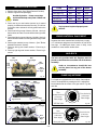
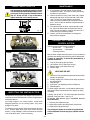
Builder
Rear Vent
Direct Vent
Models
DBR33
DBR36
DBR39
Installation Instructions & Homeowner's Manual
WARNING! IF THE INFORMATION IN THIS MANUAL IS NOT FOLLOWED EXACTLY, A FIRE OR
EXPLOSION MAY RESULT CAUSING PROPERTY DAMAGE,PERSONAL INJURY OR LOSS OF LIFE.
FOR YOUR SAFETY
FOR YOUR SAFETY
WHAT TO DO IF YOU SMELL GAS:
DO NOT STORE
OR USE GASOLINE OR OTHER
FLAMMABLE VAPOURS AND LIQUIDS
IN THE VICINITY OF THIS OR ANY
OTHER APPLIANCE.
* Do not try to light any appliance.
* Do not touch any electric switch; do not use
any phone in your building.
* Extinguish all flames.
* Immediately call your gas supplier from
your neighbours phone. Follow the gas
suppliers instructions.
* If you cannot reach your gas supplier call the
fire department.
* Installation and service must be performed
by a qualified installer, service agency or
your gas supplier.
INSTALLER: DO NOT DISCARD THIS MANUAL - LEAVE FOR HOMEOWNER
-1-
10002788
06/00 Rev. 0
TABLE OF CONTENTS
PLEASE READ THE INSTALLATION & OPERATING INSTRUCTIONS BEFORE USING APPLIANCE.
IMPORTANT: Read all instructions and warnings carefully before starting installation. Failure to follow these
instructions may result in a possible fire hazard and will void the warranty.
Installation Instructions ................................................................................................................ 3
Important Curing/Burn Information ..................................................................................... 3
Locating your Fireplace ...................................................................................................... 3
Fireplace Dimensions ......................................................................................................... 4
Mantels ..............................................................................................................................5
Mantel Chart .......................................................................................................................5
Clearance to Combustibles ................................................................................................ 5
Framing & Finishing ........................................................................................................... 5
Final Finishing .................................................................................................................... 6
Hearth ..............................................................................................................................6
Gas Specifications ............................................................................................................. 6
Gas Line Installation ........................................................................................................... 7
Remote Switch Installation ................................................................................................. 7
General Information on Assembling Vent Pipes ................................................................ 8
General Venting Information ......................................................................................................... 9
Termination Clearances ................................................................................................... 10
Rear Venting Applications ................................................................................................ 10
Rear Wall Installations ..................................................................................................... 11
Vertical Sidewall Applications .......................................................................................... 12
How To Use the Vertical Sidewall Vent Graph ................................................................. 13
General Information on Assembling Vent Pipes .............................................................. 13
Vertical Sidewall Installation ............................................................................................. 14
Below Grade Installations ................................................................................................ 16
Vertical Through the Roof Applications ............................................................................ 16
Vertical Through the Roof Installations ............................................................................ 17
Operating Instructions ................................................................................................................ 18
General Glass Information ............................................................................................... 18
Louvre Removal ............................................................................................................... 18
Glass Frame Removal ..................................................................................................... 18
Glass Cleaning ................................................................................................................. 18
Installation of Logs ........................................................................................................... 19
Ember Material Placement ............................................................................................... 19
Lava Rock ........................................................................................................................ 19
Flame Adjustment ............................................................................................................ 19
Flame Characteristics ...................................................................................................... 20
Inspecting the Venting System ......................................................................................... 20
Maintenance ..................................................................................................................... 20
Cleaning the Standing Pilot Control System .................................................................... 20
Lighting and Operating Instructions ................................................................................. 21
Troubleshooting Gas Control (820 Millivolt Gas Valve) ................................................... 22
Troubleshooting Gas Control (822 Millivolt Honeywell Valve) ......................................... 23
Replacement Parts List ............................................................................................................... 24
Replacement Parts Pictorial ............................................................................................. 25
Optional Accessories Kits ...................................................................................................... 26
Fan Kit -FK12 and FK24 .................................................................................................. 26
Wiring Instructions ............................................................................................................ 26
Electrical Box EB1 ............................................................................................................ 27
Bay Window Installation ................................................................................................... 27
Screen Kit Installation ...................................................................................................... 28
Ceramic Refractory Lining ................................................................................................ 28
Remote Control ................................................................................................................ 28
Crimped End Venting Components
.................................................................................. 29
Twist Lock Venting Components ............................................................................................... 30
-2-
INSTALLATION INSTRUCTIONS
This gas appliance should be installed by a qualified installer in
accordance with local building codes and with current CAN /
CGA-B149 (. 1 or .2) Installation codes for Gas Burning Appliances
and Equipment. or for U.S.A Installations follow local codes and/
or the current National Fuel Gas Code. ANSI Z223.1.
IMPORTANT:
PLEASE REVIEW THE FOLLOWING
CAREFULLY
FOR SAFE INSTALLATION AND OPERATION OF YOUR
DIRECT VENT FIREPLACE PLEASE NOTE THE
FOLLOWING:
It is normal for fireplaces fabricated of steel to give
off some expansion and/or contraction noises
during the start up or cool down cycle. Similar
noises are found with your furnace heat exchanger
or car engine.
Remove any plastic from trim parts before turning
the fireplace ON.
1. This fireplace gives off high temperatures and should
be located out of high traffic areas and away from
furniture and draperies.
It is not unusual for your gas fireplace to give off
some odour the first time it is burned. This is due
to the curing of the paint and any undetected oil
from the manufacturing process.
2. Children and adults should be alerted to the hazards of
the high surface temperatures of this fireplace and
should stay away to avoid burns or ignition of clothing.
Please ensure that your room is well
ventilated - open all windows.
3. CAUTION: Due to high glass surface temperature
children should be carefully supervised when they
are in same room as your fireplace.
It is recommended that you burn your fireplace for
a least six (6) hours the first time you use it. If
optional fan kit has been installed, place fan in the
"OFF" position during this time.
4. Under no circumstances should this fireplace be modified. Parts having to be removed for servicing should
be replaced prior to operating this fireplace again.
5. Installation and any repairs to this fireplace should be
carried out by a qualified service person. A professional service person should be contacted to inspect
this fireplace annually. Make it a practice to have all
of your gas fireplaces checked annually. More
frequent cleaning may be required due to excess
lint and dust from carpeting, bedding material, etc.
LOCATING YOUR GAS FIREPLACE
B
6. Control compartments, burners and air passages in
this fireplace should be kept clean and free of dust and
lint. Make sure that the gas valve and pilot light are
turned off before you attempt to clean this fireplace.
Y
A
C
X
7. The venting system (chimney) of this fireplace should
be checked at least once a year and if needed your
venting system should be cleaned.
Y
D
X
8. Keep the area around your fireplace clear of combustible materials, gasoline and other flammable vapour
and liquids. This fireplace should not be used as a
drying rack for clothing, nor should Christmas stockings or decorations be hung in the area of it.
F
Fig. 1
A) Flat on wall
C) **Island
E) *Flat on wall corner
9. Under no circumstances should any solid fuels (wood,
coal, paper or cardboard etc.) be used in this fireplace.
10. The flow of combustion and ventilation air must not be
obstructed in any way.
B)
D)
F)
Y)
Cross corner
*Room divider
Chase installation
6" minimum
Note (Fig. 1):
** Island (C) and Room Divider (D) installation is possible
as long as the horizontal portion of the vent system (X) does
not exceed 20 feet (610cm). See details in Venting Section.
* When you install your Majestic fireplace in(D) Room
divider or (E) Flat on wall corner positions (Y), a minimum
of 6 inches (153mm) clearance must be maintained from
the perpendicular wall and the front of the fireplace.
11. Whether the fireplace is installed directly on carpeting,
vinyl tile or any combustible material other than wood,
this fireplace must be installed on a metal or wood
panel extending the full width and depth of the fireplace.
12. This fireplace requires adequate ventilation and
combustion air to operate properly.
LOCATING YOUR INSTA-FLAME
E
-3-
FIREPLACE DIMENSIONS
M
O
N
M
ROD
ROH
ROW
A
E
B C
B
F
J K L
H I
A
D
Fig. 2
G
FRAMING & FINISHING
DBR33
DBR36
DBR39
A
33"
838mm
A
36"
914mm
A
39"
991mm
B
28 7/8"
733mm
B
34 1/4"
870mm
B
34 1/4"
870mm
C
16 3/8"
416mm
C
21"
533mm
C
21"
533mm
D
31"
787mm
D
33"
838mm
D
36"
914mm
E
22 1/16" 560mm
E
24"
610mm
E
24"
610mm
F
111/2"
292mm
F
16"
406mm
F
16"
406mm
G
14 3/4"
375mm
G
19"
483mm
G
19"
483mm
H
20 1/4"
515mm
H
23 7/8"
606mm
H
23 7/8"
606mm
I
24 1/2"
622mm
I
27 1/2"
698mm
I
27 1/2"
698mm
J
5"
127mm
J
6 3/4"
171mm
J
6 1/4"
159mm
K
7 1/2"
191mm
K
10"
254mm
K
8 3/8"
213mm
L
8 1/2"
216mm
L
13 1/2"
343mm
L
12 1/2"
318mm
M
36"
914mm
M
41 5/8"
1057mm
M
44"
1118mm
N
51"
1295mm
N
58 7/8"
1495mm
N
62 1/4"
1581mm
O
25 1/2"
648mm
O
29 7/8"
748mm
O
31 1/8"
790mm
ROD
12"
305mm
ROD
16 1/2"
419mm
ROD
16 1/2"
419mm
ROW
33 1/2"
851mm
ROW
36 1/2"
927mm
ROW
39 1/2"
1003mm
ROH
29"
737mm
ROH
35"
889mm
ROH
35"
889mm
Table 1
Table 2
-4-
Table 3
CLEARANCE TO COMBUSTIBLES
MANTELS
Depending on the width of the mantel it may be installed
higher or lower from the top of the louvre opening. See
drawing and chart below for proper installation height of
your combustible mantel piece. Non-combustible mantels
may be installed at any height above the appliance opening.
Back ........ 0 mm/0 inches
Side ......... 0 mm/0 inches
Floor ........ 0 mm/0 inches
Top .......... 0 mm/0 inches
;;
;;
;;
;;
Table 5
When using paint or lacquer to finish the
mantel, such paint or lacquer must be
heat resistant to prevent discolouration.
FRAMING AND FINISHING
1.
2.
V
W
3.
X
4.
WALL
A
Y
B
C
Z
D
5.
E
TOP
LOUVRE
OPENING
Choose fireplace location.
Place fireplace into position and secure to floor with
1-1/2" screws, or nails. The holes to secure the
fireplace to the floor are located just behind the
access door grill on the left and right hand side of the
fireplace.
Frame in fireplace with a header across the top. It is
important to allow for finished face when setting the
depth of the frame.
Attach fireplace to frame using adjustable frame
drywall strips(located behind access door for
shipping). Preset depth to suit facing material
(adjustable to 1/2" , 5/8" or 3/4" depths). Fig. 4.
Screw through slotted holes in drywall strip and
then screw into pre-drilled holes on fireplace side.
Measure from face of fireplace to face of drywall
strip to determine final depth. (Fig. 5 & 6)
FRONT GLASS
SIDE VIEW
C
A
B
OPTIONAL
HEARTH
GAS
KNOCK-OUT
ELECTRICAL
ELECTRICAL CABLE BOX KNOCK-OUT
KNOCK-OUT
ADJUSTABLE DRYWALL STRIP
(NAILING FLANGE)
Fig. 3
SCREW
POSITION
DRYWALL
DEPTHS
A
B
C
1/2" / 13mm
5/8" / 16mm
3/4" / 19mm
MANTEL CHART
Fig. 4
Ref.
Mantel
Ref.
Depth
Mantel From Mantel Leg from
Top Louvre
Fireplace Side
A
12" (305 mm)
10" (254mm)
V
10" (254 mm)
W
8" (203 mm)
B
10" (254 mm)
8" (203mm)
X
6" (152 mm)
C
8" (203 mm)
6" (152mm)
Y
4" (101 mm)
D
6" (152 mm)
4" (101mm)
Z
2" ( 51 mm)
E
4" (101 mm)
2" (51mm)
Table 4
Adjustable 1/2",5/8"
& 3/4" spacing
Fig. 6
Fig. 5
-5-
FINAL FINISHING
CERTIFIED TO:
ANSI Z1.88b-1999/CSA Z2.33-M-99 harmonized,
standard for Vented Gas Fireplace.
Non-combustible materials such as brick and tile can be
extended over the outer face of the unit (Do not cover
louvres or glass door). If a Trim Kit is going to be installed,
brick and tile will have to be installed flush with the side of
this appliance.
Do not use this fireplace if any part of it has
been under water. Immediately call a qualified
service technician to inspect the fireplace
and replace any part of the control which has
been under water.
HEARTH
A hearth is not mandatory but it is recommended for
aesthetic purposes. We recommend a non-combustible
hearth which does not obstruct louvre opening.
The installation of your Fireplace must
conform with local codes, or in the absence
of local codes, with National Fuel Gas Code,
ANSI Z223.1 — latest edition, or CAN 1 B1149.1 and .2 Installation Code. (EXCEPTION:
Do not derate this appliance for altitude.
Maintain the manifold pressure at 3.5 inches
W.C. for Natural Gas and 10 inches W.C. for
LP gas.)
Cold climate installation recommendation:
When installing this unit against a noninsulated exterior wall or chase, it is
mandatory that the outer walls be insulated
to conform to applicable insulation codes.
GAS SPECIFICATIONS
MODEL
FUEL
MAX.
INPUT
GAS CONTROL B.T.U.H
MIN.
INPUT
B.T.U.H.
DBR33 RN
Natural Gas
Millivolt Hi/Lo
15,000
10,500
DBR33 RP
Propane Gas
Millivolt Hi/Lo
15,000
11,250
DBR36 RN
Natural Gas
Millivolt Hi/Lo
18,000
12,600
DBR36 RP
Propane Gas
Millivolt Hi/Lo
18,000
13,500
DBR39 RN
Natural Gas
Millivolt Hi/Lo
22,000
15,400
DBR39 RP
Propane Gas
Millivolt Hi/Lo
22,000
16,500
Table 6
GAS INLET & MANIFOLD PRESSURES
NATURAL
LP (Propane)
Input Minimum
4.5" wc
11" wc
Input Maximum
7" wc
13" wc
3.5" wc
10" wc
Manifold Pressure
Table 7
-6-
REMOTE SWITCH INSTALLATION
FOR RN/RP
GAS LINE INSTALLATION
When purging gas line the front glass must
be removed.
1. Thread wire through the electrical knockout located on
either side of fireplace.. Do not cut wire or insulation on
metal edges. Ensure that wire is protected. Run the
other end to a conveniently located wall receptacle
box.
2. Attach wire to switch and install switch into receptacle
box. Attach cover plate to switch.
3. Connect wiring to gas valve. (Fig. 8)
The gas pipeline can be brought in through the right side,
left side of the appliance as well as the bottom. Knockouts
are provided at convenient locations to allow for the gas
pipe installation and testing of any gas connection. It is
most convenient to bring the gas line in from the right
side, as this allows fan installation or removal without
disconnecting the gas line.
VALVE
THERMOPILE
TPTH
The gas line connection can be made with
properly tinned 3/8" copper tubing, 3/8"
rigid pipe or an approved flex connector.
TP
TH
Always check for gas leaks with a mild
soap and water solution. Do not use an
open flame for leak testing.
OT
PIL
The gas control is equipped with a captured screw type
pressure test point, therefore it is not necessary to provide
a 1/8" test point up stream of the control.
ON/OFF SWITCH
Fig. 8
ALTERNATE SWITCH LOCATION:
Remote switch can be installed on either side of the access
door. Simply mount the switch to the switch bracket
provided. Screw the bracket on either side of the frame,
lining up the screws with the pre-punched holes. (Fig. 9)
1/2" Gas Supply
1/2" X 3/8" Reducer
3/8" Nipple
3/8" X 3/8" Shut Off Valve
3/8" Nipple
3/8" Union
3/8" Nipple
TYPICAL GAS LINE CONNECTION
Fig. 7
When using copper or flex connector use only approved
fittings. Always provide a union so that gas line can be
easily disconnected for burner or fan servicing. See Fig. 7.
See gas specification for pressure details and ratings.
The fireplace valve must not be subjected to any test
pressures exceeding 1/2 psi. Isolate or disconnect this or
any other gas appliance control from the gas line when
pressure testing.
Fig. 9
DO NOT WIRE MILLIVOLT REMOTE WALL
SWITCH FOR GAS FIREPLACE TO A 120V
POWER SUPPLY.
FOR LIGHTING INSTRUCTIONS PLEASE
REFER TO LIGHTING INSTRUCTION PAGE
-7-
GENERAL INFORMATION ON ASSEMBLING
THE VENT PIPES
TWIST LOCK PIPES
CRIMPED END PIPES
When using twist lock pipe it is not necessary to use
sealant at the twist lock joints.
Before joining elbows and pipes apply a bead of high
temperature sealant to crimped end of elbow or pipe.
(Fig. 10).
The only areas of the venting that need to be sealed with
high temperature silicone sealant are the collars on the
fireplace and termination, and the sliding joint of any
telescopic vent pipes used in the system.
Join pipes and secure joints with three (3) sheetmetal
screws. (See Fig. 10) Wipe off excess sealant.
1" From crimped end of pipe
To join the twist lock pipes together, simply align the
beads of the male end with the grooves of the female
end, then while bringing the pipes together, twist the
pipe until the flange on the female end contacts the
external flange on the male end.
1''
It is recommended that you secure the joints with 3
sheet metal screws however this is not mandatory with
twist lock pipe.
Screw Holes
BEAD LOCATION
To make it easier to assemble the joints we suggest
putting a lubricant (Vaseline or similar) on the male end
of the twist lock pipe.
Fig. 10
CANADIAN INSTALLATIONS:
The venting system must be installed in accordance with
the current CAN/CGA-B149 (.1 or .2) installation code.
TWIST LOCK PIPE JOINT
U.S.A. INSTALLATIONS:
The venting system must conform with local codes and/or
the current National Fuel Gas Code, ANSI Z223.1.
Only venting components manufactured by The CFM
Majestics Products Company may be used.
Screw Holes
-8-
Fig. 11
GENERAL VENTING INFORMATION
There must not be any obstruction such as bushes, garden
sheds, fences, decks or utility buildings within 24" from the
front of the termination hood.
Your fireplace is approved to be vented either through
the side wall, or vertical through the roof.
-
-
-
Only Majestic venting components specifically
approved and labelled for this fireplace may be
used.
Minimum clearances between vent pipes and
combustible materials is one (1") inch (25 mm),
except where stated otherwise.
Venting terminals shall not be recessed into a wall
or siding.
Horizontal venting must be installed on a level
plane without an inclining or declining slope.
Do not locate termination hood where excessive snow or
ice build up may occur. Be sure to check vent termination
area after snow falls, and clear to prevent accidental
blockage of venting system. When using snow blowers,
make sure snow is not directed towards vent termination
area.
Location of Vent Termination
It is imperative that the vent termination be located observing the minimum clearances as shown on this page.
;
;;
;;;;
;
;
;
;;
;
*Check with local codes or in absence of local codes, with
National Fuel Gas Code, ANSI Z223.1 - latest edition for USA, or
CAN 1 B1-149.1 and .1 Installation Code for Canada.
N
H
D
V
E
B
L
C
Fixed
Closed
Ope
F
B
V
Openable
nab
V
B
le
B
V
Fixed
Closed
B
V
J
V TERMINATION CAP
X
B=
C=
D=
E=
F=
G=
H=
G
M
V
G
V
K
V
X
A
X AIR SUPPLY INLET
clearance above grade, veranda, porch, deck, or
balcony [* 12 inches (305mm) minimum]
clearance to window or door that may be opened
12" (306mm).
clearance to permanently closed window [minimum
12 inches (305mm) recommended to prevent condensation on window]
vertical clearance to ventilated soffit located above
the termina/ within a horizontal distance of 24 inches
(610mm) from the centre-line of the terminal [18
inches (458mm) minimum]
clearance to unventilated soffit [12 inches (305mm)
minimum
clearance to outside comer see next page
clearance to inside comer see next page
* not to be installed above a meter/regulator assembly within 36 inches (914mm) horizontally from the
centre-line of the regulator
I
G
A
A=
N
G GAS METER
RESTRICTED AREA
(TERMINATION PROHIBITED) Fig. 12
I=
clearance to service regulator vent outlet [*72 inches
(1828mm) minimum]
J = clearance to non-mechanical air supply inlet to
building or the combustion air inlet to any other
fireplace [ *12 inches (305mm) minimum]
K = clearance to a mechanical air supply inlet [* 72 inches
(1828mm) minimum]
L = † clearance above paved side-walk or a paved
driveway located on public property [*84 inches
(2133mm) minimum]
M = clearance under veranda, porch, deck [*12 inches
(305mm) minimum ‡]
N = Clearance above a roof shall extend a minimum of
24" (610mm) above the highest point when it passes
through the roof surface, and any other obstruciton
within a horizontal distance of 18" (450mm).
A
†
a vent shall not terminate directly above a side-walk or paved driveway which is located between two single family
dwellings and serves both dwellings *
‡ only permitted if veranda, porch, deck, is fully open on a minimum 2 sides beneath the floor *
*
check with local codes, or in the absence of local codes, with National Fuel Gas Code, ANSI Z223.1 - latest edition
for USA, or CAN 1B1-149.1 and .2 Installation Code for Canada.
Note: Local codes or regulations may require different clearances.
-9-
;; ; ;;;
;;
;;;;
;
;;
;;
;;
Termination Clearances
Termination clearances for buildings with combustible and noncombustible exteriors.
Inside Corner
Recessed Location
Outside Corner
A=
Combustible
6"(152mm)
Noncombustible
2"(50mm)
A
V
D
B=
Combustible
6"(152mm)
Noncombustible
2"(50mm)
V
C
C
E
V
B
Balcony with perpendicular side wall
Balcony with no side wall
C = Maximum depth of 48"
(1219mm) for recessed
location.
H
G
V
V
G=
Combustible&
Non-Combustible
12"(305mm)
Combustible &
Non-Combustible
D = Minimum width for back wall
of a recessed location.
Combustible 38"(965mm)
Noncombustible 24"(610mm)
J
E = Clearance from corner in
recessed location.
Combustible 6"(152mm)
Noncombustible 2"(50mm)
H = 24"(610mm)
J = 20"(508mm)
Fig. 13
REAR VENTING APPLICATIONS
*IMPORTANT*
DIRECT THROUGH
SIDEWALL
Note: It is not necessary
to seal the
vent pipe joints for any straight out the wall rear vent applications.
Note:
Vent Starter Kit Model 7DVRVT must be
used in straight out the wall rear vent applications.
Maximum Vent Length .......................... 20" (508mm)- Fig. 14
Minimum
clearance
between vent pipes and
combustible materials is
one (1") inch (25 mm) on
sides and bottom and two
(2") inch (50 mm) on top.
When vent termination
exits through foundation
less than 20" (508mm)
below siding outcrop, the
vent pipe must flush up
with the siding. A 7DVSS
must also be used.
20"
508mm
45°
20"
508mm
45°
20" (508mm)
TOP VIEW
TOP VIEW
CROSS CORNER VENT
TO THE LEFT.
TOP VIEW
CROSS CORNER VENT
TO THE RIGHT.
Fig. 14
- 10 -
STEP 3
REAR WALL INSTALLATIONS
Measure from fireplace collar or elbow face to face of
outside wall (add 2" for vent pipe overlap. Mark pipes and
cut to length. It is very important that the two pipes are flush
with the outside wall once the fireplace is in its final location.
STEP 1
Locate vent opening on wall. To locate hole centre consult
with appropriate fireplace dimensions, page 4. Frame as
shown below.
ZERO
CLEARANCE
SLEEVE
Straight Out Thru the Wall Application
Vent Opening —
Combustible Wall
FIRESTOP
(240mm)
9-3/8"
10-3/8"
(255mm)
Fig. 17
(framing detail)
Vent Opening —
Noncombustible Wall
STEP 4
Slip 4" and 7" pipes onto respective flue collars. Make sure
to fix to the fireplace collar the 4" pipe with three (3) screws
before fixing the 7" pipe on the 7" collar. Both pipes must
be on a level plane. Fig. 17.
7-1/2"
(190mm)
Fig. 15
Combustible Walls. Cut a 10-3/8"H x 9-3/8"W (265mm
x 240mm) hole through the exterior wall and frame as
shown. Fig. 15.
STEP 5
Guide the vent termination 4" collar into the 4" pipe then the
7" collar into the 7" pipe. Do not force the venting into
position. If the pipes do not line up with the termination
collars, disassemble pipes and reattach to the fireplace
collar. (Fig. 18)
Non-Combustible Walls: Hole opening must be 7.5"
(190mm) in diameter.
STEP 2
STEP 6
Measure wall thickness and cut adjustable zero clearance
sleeve parts to proper length (MAXIMUM 12"/305mm).
Adjust sleeve to maximum (10-3/8 x 9-3/8). and attach to
firestop with #8 sheet metal screws (supplied). (Fig. 16)
Install firestop assembly.
#8
SCREWS(2)
Maximum Length
12" (294mm)
FINISHED
WALL
ADJUSTABLE
ZERO CLEARANCE
SLEEVE
#8
SCREWS(2)
#8
SCREWS(2)
ADJUSTABLE ZERO
CLEARANCE SLEEVE
;;
;
Secure fireplace to floor through floor holes and adjustable
frame drywall strip (nailing flange) to frame. (See Framing
& Finishing Section)
FIRESTOP
Fig. 16
- 11 -
VENT
TERMINATION
Fig. 18
The maximum number of 90 degree elbows per side wall
installation is three (3) plus one transition elbow, 7DVRT90
off back of unit.
VERTICAL SIDEWALL APPLICATIONS
Since it is very important that the venting system
maintain its balance between the combustion air intake
and the flue gas exhaust, certain limitations as to vent
configurations apply and must be strictly adhered to.
The maximum number of 45 degree elbows permitted per
side wall installation is two (2). These elbows can be
installed in either the vertical or horizontal run.
The graph showing the relationship between vertical and
horizontal side wall venting will help to determine the
various vent lengths allowable. Fig. 23.
When one 900 elbow is installed directly onto another off
the back of the fireplace the maximum horizontal vent
length is 36" (914mm). Fig. 20.
;;
;
Minimum clearance between vent pipes and
combustible materials is one (1") inch (25
mm) on top, bottom and sides unless
otherwise noted.
MAXIMUM
3' (914mm)
When vent termination exits through
foundation less than 20" below siding
outcrop, the vent pipe must flush up with the
siding. A 7DVSS must also be used.
7DVRT90
ELBOW
It is always best to locate the fireplace in such a way that
minimizes the number of offsets and horizontal vent
length.
SIDE VIEW
Fig. 20
For each 45 degree elbow installed in the
horizontal run (while maintaining a constant
horizontal plane), the length of the horizontal
run MUST be reduced by 18" (457mm). This
does not apply if the 45 degree elbows are
installed on the vertical part of the vent system.
The horizontal vent run refers to the total
length of vent pipe from the flue collar of the
fireplace to the face of the outer wall.
Horizontal plane means no vertical rise
exists on this portion of the vent assembly.
If a 90 degree elbow is used in the horizontal
vent run (level height maintained) the maximum horizontal vent length is reduced by 36
inches. Fig. 21. This does not apply if the 90
degree elbows are used to increase or redirect a vertical rise.
For some installations, it may be desirable to
have some amount of the horizontal vent run
immediately after the fireplace. A vertical
rise must be used but can be located anywhere in the vent system, to meet the perimeters identified in the venting graph.
;;
;;
;;
;;
The maximum horizontal vent run is 20 feet (6100mm)
when the vertical vent rise is 7.5 feet (2286mm). Fig. 19
Example: According to the vent chart the maximum
horizontal vent length is 20 ft.when the vertical height is 7.5
ft. from fireplace base height. If one 90 degree elbow is
required in the horizontal vent it must be reduced to 17 ft.
MAXIMUM
20 ft. (6100mm)
48"
(1220mm)
12"
(305mm)
84"
2134mm
15 ft.
(4572mm)
90" (2286mm)
VERTICAL
DIMENSION
7.5 ft. MINIMUM
WHEN HORIZONTAL
RUN IS 20 ft.
120"
3048mm
90o elbow=3'
90"
2286mm
7DVRT90
ELBOW
SIDE VIEW
Fig. 19
- 12 -
Fig. 21
The maximum number of elbow degrees in a system is
270 o. (This does not include transition elbow from rear
vent to vertical vent.) Fig. 22.
Sample:
(Fig. 20)
1
2
3
4
90 o
45 o
45 o
90 o
-
270 o
30
29
28
27
VERTICAL DIMENSION FROM THE FLOOR OF THE UNIT
TO THE CENTRE OF THE HORIZONTAL VENT PIPE
Total
-
VERTICAL SIDEWALL VENTING GRAPH
(Dimensions in Feet)
26
25
24
23
22
21
20
19
18
17
16
15
14
13
12
eg: A
11
10
9
8
7
eg: B
6
Fig. 22
5
4
3
HOW TO USE THE VENT GRAPH
3
1. Determine the height of the centre of the horizontal
vent pipe exiting through the outer wall. Using this
dimension on the Sidewall Vent Graph (Fig. 21),
locate the point it intersects with the slanted graph
line.
2. From the point of this intersection, draw a vertical
line to the bottom of the graph.
3. Select the indicated dimension, and position the
fireplace in accordance with same.
EXAMPLE A:
If the vertical dimension from the floor of the unit is 11
feet (3352mm) the horizontal run to the face of the outer
wall must not exceed 14 feet (4267mm).
4
5
6
7
8
9 10 11 12 13 14 15 16 17 18 19 20
HORIZONTAL DIMENSION
SEE PAGE 15 FOR VENTING
REQUIREMENTS FOR SNORKELS.
EXAMPLE B:
If the vertical dimension from the floor of the unit is 7 feet
(2133mm), the horizontal run to the face of the outer wall
must not exceed 8-1/2 feet (2590mm).
- 13 -
Fig. 23
STEP 2
VERTICAL SIDEWALL INSTALLATION
Fig. 26. Measure wall thickness and cut adjustable zero
clearance sleeve parts to proper length (MAXIMUM 12"/
305mm). Adjust sleeve to minimum (9-3/8" x 9-3/8") and
attach to firestop with #8 sheet metal screws (supplied).
Install firestop assembly.
STEP 1
Locate vent opening on the wall. It may be necessary to first
position the fireplace and measure to obtain hole location.
Depending on whether the wall is combustible or noncombustible, cut opening to size. Fig. 25.
(For combustible walls first frame in opening).
Zero clearance sleeve is only required for
combustible walls.
VERTICAL SIDEWALL APPLICATION
#8
SCREWS(2)
Maximum Length
12" (294mm)
Vent Opening —
Combustible Wall
ADJUSTABLE
ZERO CLEARANCE
SLEEVE
#8
SCREWS(2)
(240mm)
9-3/8"
#8
SCREWS(2)
ADJUSTABLE ZERO
CLEARANCE SLEEVE
FIRESTOP
9-3/8"
(240mm)
DRYWALL
WOOD FRAMING
(framing detail)
WALL EXTERIOR
Vent Opening —
Noncombustible Wall
FIRESTOP
7-1/2"
(190mm)
VENT PIPE
COMBUSTIBLE WALLS (Fig. 25): Cut a 9-3/8"H x 9-3/8"W (240
mm x 240 mm) hole through the exterior wall and frame as shown
(Fig. 24).
NON-COMBUSTIBLE WALLS (Fig. 25): Hole opening must be
7.5" (190 mm) in diameter.
ZERO
CLEARANCE
SLEEVE
FLUSH WITH
WALL
EXTERIOR
Fig. 26
Fig. 25
- 14 -
;;
;;
;;
;;
STEP 3
X
(Fig. 27) Apply a bead of high temperature sealant to the
inner and outer flue collars of the fireplace and using
appropriate venting component(s) attach to fireplace with
three (3) screws. Follow with the installation of the inner
and outer elbow. Again secure joints with three (3) sheet
metal screws. Wipe off any excess high temperature
sealant.
ENSURE PIPES
ARE CONCENTRIC
X
7DVRT90
BEAD OF
SEALANT
STEP 4
;
;
;
;
;
Fig. 27
STEP 6
Fig. 25
;;
;;
;
;;
;;
(Fig. 28) Measure the horizontal length requirement
including a 2" (50mm)overlap, i.e. from the elbow to the
outside wall finish plus 2" (or the distance required if
installing a second 90o elbow).
X
X
Always install
horizontal
venting on a
level plane.
Fig. 28
STEP 5
(Fig. 29) Use the appropriate length of pipe section –
telescopic or fixed – and install. The 20" (508mm) section
of pipe which goes through the wall is packaged with the
7DVSK kit, and can be cut to suit if necessary.
;;
;;
;;
;;
; ;
; ;
(Fig. 30) Apply high temperature sealant to 4" and 7"
collars one inch away from crimped end. Guide the vent
termination 4" and 7" collars into their respective vent
pipes. Double check that the vent pipes overlap the collars
by 2" (50mm). Secure the termination to the wall with
screws provided and caulk around the wall plate to
weatherproof.
X
Fig. 30
STEP 7
Support the horizontal pipes every 36 inches (914mm)
with metal pipe straps. Make sure that the horizontal vent
pipe is installed on a level horizontal plane.
STEP 8
Recheck the fireplace to make sure that it is levelled,
properly positioned, and nailed or screwed to the floor.
Sealing vent pipe and firestop gaps with hitemperature sealant will restrict cold air being
drawn in around fireplace.
If applied, the fireplaces adjustable frame drywall strips
(nailing flanges) should be fastened. See "Framing &
Finishing.
- 15 -
BELOW GRADE INSTALLATIONS
When it is not possible to meet the required vent terminal
clearances of 12 inches (305mm) above grade level a
model #7DVSKS vent kit is required. It allows installation
depth of down to 7 inches (178mm) below grade level. The
7 inches is measured from the centre of the horizontal vent
pipe as it penetrates through the wall.
FOUNDATION
RECESS
SNORKEL
WATERTIGHT
SEAL
AROUND
PIPE
If venting system is installed below ground,
we recommend a window well with adequate
and proper drainage.
WALL
SCREWS
SHEET METAL
SCREWS
Fig. 32
If the foundation is recessed, use recess brackets (not
supplied) for securing lower portion of the snorkel. Fasten
brackets to wall first and then secure to snorkel with self
drilling #8 x 1/2 sheet metal screws. It will be necessary to
extend vent pipes out as far protruding wall face (Fig. 32).
Ensure sidewall venting clearances are observed.
The maximum horizontal run with 24" (610mm)
vertical rise is 36" (914mm) from the back of the
fireplace to the face of the exterior wall. See
vent graph (Fig. 21) for extended horizontal run
if the vertical exceeds 24" (610mm).
VERTICAL THROUGH THE
ROOF APPLICATIONS
1. Establish vent hole through the wall. See page 14
2. Remove soil to a depth of approximately 16"
(406mm) below base of snorkel. Install window well
(not supplied). Refill hole with 12" (305mm) of
coarse gravel leaving a clearance of approximately 4"
(100mm)below snorkel. (Fig. 31)
3. Install vent system. See page 13, Steps 2 through 5.
4. Ensure a watertight seal is made around the vent
pipe coming through the wall.
5. Apply high temperature sealant caulking (supplied)
around the 4 and 7 inch 7DVSKS's snorkel collars.
6. Slide into vent pipe and secure to the wall.
7. Level the soil so as to maintain a 4"
(100mm)clearance below snorkel (Fig. 31).
MAXIMUM
10 FT
(3048mm)
MINIMUM
8 FT./
MAXIMUM
40 FT.
VERTICAL
RISE
PIPE STRAPS
EVERY 3'
(914mm)
Fig. 33
ZERO CLEARANCE
SLEEVE IF REQUIRED
FIRESTOP
7" PIPE
This Gas Fireplace has been approved for,
a) Vertical installations up to 40 feet (12 metres) in height.
Up to a 10 ft.(3048mm) horizontal vent run can be
installed within the vent system using a maximum of
three 90o elbows.
b) Up to two 45o elbows may be used within the horizontal
run. For each 45o elbow used on the horizontal level
the maximum horizontal length must be reduced by 18
inches (457mm).
Example: Maximum horizontal length
0
- 45o elbows 10 ft. (3048mm)
1
- 45o elbows 8.5 ft. (2590mm)
2
- 45o elbows 7 ft. (2133mm)
7DVSKS
(SNORKEL)
SCREWS
MINIMUM
4" CLEARANCE
GROUND
WINDOW WELL
GRAVEL
24"/608mm
MINIMUM*
DRAIN
FOUNDATION WALL
* A minimum of 24"/608mm
vertical pipe must be installed when
using the 7DVSKS/7TDVSKS kit.
c) A minimum of an 8 ft. vertical rise.
d) Two sets of 45 degree elbow offsets within these
vertical installations. From 0 to a maximum of 8 ft.
(2438mm) a vent pipe can be used between elbows.
(Fig. 35)
e) 7DVCS must be used to support offsets. (Fig. 35)
This application will require that you first determine the roof
pitch and use the appropriate 7DVSKV (A,B or F). (see
Venting Components, page 28)
* The 22" vertical rise (center to
center) of the snorkel may be
included for calculation of max.
horizontal run.
Fig. 31
DO NOT BACK FILL AROUND SNORKEL.
SOIL SHOULD NOT BE LESS THAN 4"
(100mm) BELOW SNORKEL.
- 16 -
VERTICAL THRU THE ROOF INSTALLATION
1. Locate your fireplace.
2. Plumb to centre of the (4") 90º transition elbow
(7DVRT90) from ceiling above and mark position.
3. Cut opening equal to 9-3/8" x 9-3/8" (240 mm x 240
mm).
4. Proceed to plumb for additional openings through the
roof. In all cases, the opening must provide a minimum
of 1 inch clearance to the vent pipe, i.e., the hole must
be a minimum of 9-3/8" x 9-3/8" (240 mm x 240 mm).
5. Place firestop(s) #7DVFS into position and secure.
(Fig. 38)
6. Install roof support (Fig. 35) and roof flashing making
sure upper flange of flashing is below the shingles.
(Fig. 39)
7. Install appropriate pipe sections until above the flashing. (See Fig. 39 for #'s 7, 8 and 9).
8. Install storm collar and seal around the pipe.
9. Add additional vent lengths for proper height.
10. Apply high temperature sealant to 4" and 7" collars of
vent termination and install.
MAX.
8 FEET
2438mm
45°
40 FEET
(12.2m)
MAX.
8 FEET
2438mm
TYPICAL 7DVCS
APPLICATION
Fig. 35
45°
TYPICAL ROOF
SUPPORT
APPLICATION
TYPICAL OFFSET INSTALLATION
Fig. 36
Fig. 34
Attic
Insulation
Shield
11"
11"
JOIST
VENT TERMINATION
STORM COLLAR
ROOF
ROOF FLASHING
2' Min.
Ceiling
Installation
ROOF SUPPORT
UPPER FLOOR
11"
ATTIC INSULATION
JOIST
CEILING JOISTS
FIRESTOP
SPACER
JOISTS
40 FEET
(12.2m)
11"
NAILS (4)
ATTIC INSULATION
SHIELD
Fig. 38
Fig. 38 If there is a room above ceiling level,
firestop spacer must be installed on both the
bottom and the top side of the ceiling joists. If
an attic is above ceiling level a 7DVAIS (Attic
Insulation Shield) must be installed.
Fig. 39. The enlarged ends of the vent section
always face downward.
TYPICAL STRAIGHT-UP INSTALLATION
Fig. 37
SHEETMETAL
SCREWS (#5) —
3 PER JOINT
SEALANT
Clearance above a roof shall extend a minimum of 24" (610mm) above the highest point
when it passes through the roof surface, and
any other obstruciton within a horizontal
distance of 18" (450mm).
STORM
COLLAR
Fig. 39
- 17 -
OPERATING INSTRUCTIONS
GENERAL GLASS INFORMATION
GLASS
FRAME
FIREPLACE
FRONT
Only glass approved for use in products
may be used for replacement.
1 . The use of subsitute glass will void all product warranties.
2. Care must be taken to avoid breakage of the glass.
3. Under no circumstances should this appliance be
operated without the front glass or with a broken glass.
Replacement of the glass (with gasket) as supplied by
the manufacturer should be done by a licenced qualified
service person.
CLAMPS
WINDOW
FRAME
LOUVRE REMOVAL
WINDOW
FRAME
(Fig. 40) To remove top louvre pull louvre up and then
lift out.
PULL
CLAMP HOOK
PUSH
CLAMP HANDLE
Fig. 41
2.
GLASS CLEANING
LOUVRE
1.
GLASS
PANEL
It will be necessary to clean the glass periodically. During
start-up condensation, which is normal, forms on the inside
of the glass and causes lint, dust and other airborne
particles to cling to the glass surface. Also initial paint
curing may deposit a slight film on the glass. It is therefore
recommended that the glass be cleaned two or three times
with a non-ammonia household cleaner and warm water
(we recommend gas fireplace glass cleaner). After that the
glass should be cleaned two or three times during each
heating season depending on the circustances present.
Fig. 38
GLASS FRAME REMOVAL
Clean glass after first two weeks of operation.
Do not clean glass when hot.
Do not use abrasive cleaners.
Do not strike or slam the glass.
1.
2.
3.
4.
5.
Shut off gas.
Let the fireplace cool if it has been operating.
Remove top louvre. (See Louvre Removal)
Open the lower louvre assembly.
Release the two clamps at the bottom of the window
frame by pulling down on the clamp handles.
6. Lift off the glass frame as shown.
7. To reinstall glass follow the above procedure in
reverse. (Fig. 41)
- 18 -
INSTALLATION OF LOGS
LOGS
1 . Remove front glass. (See "Glass Removal" Section)
2. Remove logs from the packaging.
As with all plastics — these are not toys
and should be kept away from children and
infants.
3. Place rear log on rear bracket (ensure log is seated
properly, leveled and centered to the unit), so it will not
move from side to side and it is firmly positioned on the
bracket.
4. Place front left log on top of burner, left side. Use log's
bottom holes to locate it into the left bracket log locator
studs.
5. Place front right log on top of burner, right side. Use log's
bottom holes to locate it into the right bracket log locator
studs.
6. Place ember material on top of burner. (See "Ember
Material Placement" Section).
7. Place top left log onto locator notches. Ensure log is
secure.
8. Place top right log onto locator notches. Ensure log is
secure.
DBR33
DBR36
DBR39
Front Left Log
BA2
BB6
BC5
Front Right Log
BA3
BB7
BC6
Rear Log
BA4
BB8
BC7
Top Left Log
BA5
BB9
BC8
Top Right Log
BA6
BB10
BC9
Top logs must be placed properly onto
notches.
EMBER MATERIAL PLACEMENT
Separate the ember material into small pieces, roughly
1/2" in diameter and place onto the burner in front of the
front logs. Do NOT pack down, leave in fluffy, loose
condition for most realistic ember effect.
LAVA ROCK
DBR33
BA5
Log Top Left
BA6
Log Top Right
The lava rock provided with this fireplace must be
placed on the firebox base on either side of the burner
assembly.
BA4
Log Rear
BA2
Log
Front
Left
Under no circumstances should this lava
rock be placed on any part of the burner
assembly.
BA3
Log Front
Right
FLAME ADJUSTMENT
Fig. 42
DBR36
BB8
Log Rear
BB9
Log Top Left
BC7
Log Rear
Turn
counterclockwise
to increase
flame height
BB7
Log Front Right
Fig. 43
BB6
Log Front Left
DBR39
For fireplaces equipped with Hi/Lo valves, flame adjustment is accomplished by rotating the Hi/Lo adjustment
knob located near the centre of the gas control. Fig. 46a
and 46b.
BB10
Log Top Right
BC8
Log Top Left
BC9
Log Top Right
BC6
Log Front
Right
BC5
Log Front Left
SIT 820 Valve
Fig. 46a
Turn
counterclockwise
to decrease
flame height
Turn clockwise
to increase
flame height
Honeywell Valve
Fig. 44
- 19 -
Turn clockwise
to decrease
flame height
Fig. 46b
FLAME CHARACTERISTICS
MAINTENANCE
1. It is important to keep the burner and the burner
compartment clean. This must be done periodically,
at least once per season.
2. Clean the brass trim using a soft clean cloth, slightly
dampened with lemon oil and buff with a soft clean
cloth. Do NOT use brass polish or household
cleaners as these products will damage the brass
trim. Lemon oil can be obtained at supermarkets or
hardware stores.
3. The optional FK24 fan does require periodic cleaning. Check the area under the control door and in
front of the fan and wipe or vacuum at least once a
month during the operating season.
4. Contact your local representative to arrange an
annual service program.
It is important to periodically perform a visual
check of the pilot and the burner flames. Compare them to the pictorials illustrated below
(Fig. 47, 48, 49, and 50). If any of the flames
appear abnormal call a service person.
Fig. 47
DBR33
CLEANING THE STANDING PILOT
CONTROL SYSTEM
The burner and control system consists of:
• burner tube
• gas orifices
• pilot assembly • thermopile
• millivolt gas valve
Fig. 48
DBR36
Most of these components may require only an occasional
checkup and cleaning and some may require adjustment.
If repair is necessary, it should be performed by a
qualified technician.
1.
2.
3.
4.
Fig. 48
DBR39
Turn off pilot light at gas valve side
Let fireplace cool if it has been running.
Remove glass. (see Glass Removal)
Remove logs.
LOGS MAY BE HOT
INSPECTING THE VENTING SYSTEM
5. Vacuum burner compartment especially around orifice
primary air openings.
6. Visually inspect pilot. Brush or blow away any dust or
lint accumulation.
7. Reinstall logs.
8. Ignite pilot - see Operating Section of Manual.
8. Reinstall glass.
To obtain proper operation, it is imperative that the pilot
and burner's flame characteristics are steady, not lifting
or floating.
This appliance venting system was designed and constructed
to develop a positive flow adequate to remove flue gases to the
outside atmosphere.
Typically, the top 3/8" or 1/2" of the thermopile should be
engulfed in the pilot flame. See Fig. 47.
To adjust pilot burner (by a Qualified Service
Representative)
Fig. 50
Any foreign objects in the venting system, except those
designed specifically for the venting system, may cause
spillage of flue gases.
1. Remove pilot adjustment cap.
2. Adjust pilot screw to provide properly sized flame.
3. Replace pilot adjustment cap.
To inspect the venting system, make sure the main gas valve
is off. Remove glass frame (See Glass Frame Removal
Section). Using a flashlight, check the area above the baffle
in the combustion dome. Clean if necessary.
The primary air shutter is set at factory and should
only be adjusted (if necessary) by a qualified service
person.
- 20 -
LIGHTING AND OPERATING INSTRUCTIONS
FOR YOUR SAFETY READ BEFORE LIGHTING
WARNING: If you do not follow these instructions exactly, a fire or explosion may result
causing property damage, personal injury or loss of life.
A.
This fireplace has a pilot which must be lit manually.
When lighting the pilot follow these instructions exactly.
BEFORE LIGHTING smell all around the fireplace area for
gas. Be sure to smell next to the floor because some gas
is heavier than air and will settle on the floor.
B.
WHAT TO DO IF YOU SMELL GAS
•
Do not try to light any fireplace.
•
Do not touch any electric switch
•
Do not use any phone in your building
•
Immediately call your gas supplier from a neighbor's
phone. Follow the gas supplier's instructions.
•
If you cannot reach your gas supplier, call the Fire
Department
C.
Use only your hand to push in or turn the gas control
knob. Never use tools. If the knob will not push in or turn
by hand, do not try to repair it, call a qualified service
technician. Applying force or any attempted repair may
result in a fire or explosion.
D.
Do not use this fireplace if any part has been under water.
Immediately call a qualified service technician to inspect
the fireplace and to replace any part of the control system
and any gas control which has been under water.
LIGHTING INSTRUCTIONS
1.
STOP! Read the safety information above on this
page.
Turn off all electrical power to the fireplace.
For MN/MP/TN/TP appliances ONLY, go on to Step 4.
For RN/RP appliances turn the On/Off switch to off
position or set thermostat to lowest level.
Open control access panel.
Push in gas control knob slightly and turn clockwise
to
"OFF". Do not force.
2.
3.
4.
5.
10. Push the control knob all the way in and hold.
Immediately light the pilot by repeatedly depressing
the piezo spark ignitor until a flame appears.
Continue to hold the control knob in for about one
(1) minute after the pilot is lit. Release knob and it
will pop back up. Pilot should remain lit. If it goes
out, repeat steps 5 through 8.
OR
PI
LO
T
OFF
LO
7.
8.
9.
PI LOT
6.
F
OT
EURO SIT
ON
ON
it
PIL
OF
HI
OFF
SIT NOVA
HONEYWELL
Wait five (5) minutes to clear out any gas. Then smell
for gas, including near the floor. If you smell gas,
STOP! Follow "B" in the safety information above on
this page. If you don't smell gas, go to the next step.
Remove glass door before lighting pilot. (See Glass
Frame Removal in manual).
Visibly locate pilot by the main burner.
Turn knob on gas control counterclockwise
to "PILOT".
11.
12.
13.
14.
• If knob does not pop up when released, stop and
immediately call your service technician or gas
supplier.
• If after several tries, the pilot will not stay lit, turn
the gas control knob to "OFF" and call your service
technician or gas supplier.
Replace glass door.
Turn gas control knob to "On"
position.
For RN/RP appliances turn the On/Off switch to "On"
position or set thermostat to desired setting.
Turn on all electrical power to the fireplace.
TOTURN
TURNOFF
OFF GAS
GAS TO
TO
TOAPPLIANCE
FIREPLACE
1.
2.
3.
Turn the On/Off switch to Off position or set the
thermostat to lowest setting.
Turn off all electric power to the fireplace if service
is to be performed.
Open control access panel.
4.
5.
- 21 -
Push in gas control knob slightly
and turn clockwise
to
"OFF". Do not force.
Close control access panel.
TROUBLE SHOOTING THE GAS CONTROL SYSTEM
SIT 820 NOVA MILLIVOLT VALVE
GLASS DOOR TO BE REMOVED BEFORE SERVICE WORK
CHECK
GAS SUPPLY ON
NO
▼
START
• SHUTOFF VALVE OPEN
• CONFIRM GAS HOOK-UP
LIGHT PILOT WITH
PIEZO IGNITION
NO
▼
▼
YES
•
•
•
•
ELECTRODE GAP MIN. 1/8"
ELECTRODE CRACKED
ELECTRODE CABLE ATTACHED
PIEZO IGNITOR GENERATES
SPARK
• ELECTRODE CABLE NOT
GROUNDED
PILOT STAYS ON
NO
▼
▼
YES
• FLAME ENGULFING
THERMOCOUPLE BY 3/8"
• THERMOCOUPLE ATTACHED
TO VALVE
• MNIMUM MILLIVOLT:
OPEN CIRCUIT 18MV
CLOSED CIRCUIT 5MV
• VENT SAFETY SWITCH TIGHT
AND NO SHORTS
(FOR UNITS EQUIPPED WITH
VENT SAFETY SWITCH)
MAIN BURNER ON
NO
▼
▼
- 22 -
• REMOTE SYSTEM ON
• REMOTE SYSTEM WIRE
SHORTING OUT
• MINIMUM MILLIVOLT:
OPEN CIRCUIT 300MV
CLOSED CIRCUIT 165MV
• FLAME ENGULFING
THERMOPILE/THERMOCOUPLE
• VALVE IS IN ON POSITION
TROUBLE SHOOTING THE GAS CONTROL SYSTEM
HONEYWELL MILLIVOLT VALVE
START
CHECK
GAS SUPPLY ON
YES
PILOT LIGHTS WITH
PIEZO IGNITOR
NO
YES
PILOT STAYS LIT
NO
YES
PILOT LIGHTS MAIN
BURNER
• SUPPLY LINE HOOKED UP
• SHUTOFF VALVE OPEN
NO
• LOCKOUT HAS ENGAGED. WAIT
60 SECONDS AND TRY AGAIN.
• PIEZO NOT TIGHT ENOUGH
FOR GOOD GROUND.
• FOR SPARK AT ELECTRODE
WHILE DEPRESSING PIEZO
(RED BUTTON) — 1/8" GAP TO
PILOT HOOD NEEDED.
• ALL WIRING CONNECTIONS
• REPLACE PIEZO IGNITOR
• THERMODISK
• FOR AIR IN THE LINES
• THERMOPILE NEEDS A
MINIMUM 325mV. ADJUST
PILOT FLAME HEIGHT.
• ALL WIRING CONNECTIONS.
• REPLACE THERMOPILE
• THERMOCOUPLE NEEDS A
MINIMUM OF 14mV.
• DEFECTIVE VALVE. TURN TO
PILOT, METER SHOULD READ
GREATER THAN 100 mV. IF
NOT, REPLACE.
• THERMODISK
• WALL SWITCH IS NOT
TURNED ON. WATCH
FOR GROUNDED WIRES!
•THERMOPILE NEEDS A
MINIMUM 325mV.
• PLUGGED BURNER ORIFICE.
NO
YES
SYSTEM OK.
- 23 -
REPLACEMENT PARTS LIST - REAR BUILDER SERIES
DESCRIPTION
1.
1a.
1b.
1c.
1d.
1e.
2.
3.
4a.
4b.
5.
6a.
6b.
7a.
7b.
8a.
8b.
9.
10.
11.
12.
13.
14a.
14b.
15.
16a.
16b.
17.
18.
19.
20.
21.
22.
23.
24.
25.
26.
27.
28.
29.
30.
31.
32.
33.
34a
34b
35.
36.
37.
38.
39.
40.
Log Set Complete
Log Front Left
Log Front Right
Log Rear
Log Top Left
Log Top Right
Lava Rock (Package)
Ember (Package)
Burner with Tiles Assy (Nat)
Burner with Tiles Assy (Prop)
Ceramic Tile (Single)
Orifice Burner (Nat)
Orifice Burner (Prop)
Orifice Pilot (Nat)
Orifice Pilot (Prop)
Pilot Assembly Nova (Nat)
Pilot Assembly Nova (Prop)
Pilot Tubing w/ fittings
Manifold Tubing w/ fittings
Thermocouple
Thermopile
Electrode Ignitor Nova
Cable Ignitor (RN/RP)
Cable Ignitor (EN/EP)
Ignitor Piezzo
Valve Nova 820 (RN)
Valve Nova 820 (RP)
Fan with bracket
Electrical Cord (6ft)
Fan Temperature Sensor
Speed Control
Speed Control Knob
Glass with Gasket
Gasket Glass
Frame Window
Clamp Frame Window
Trim Frame Window (PB) (w/2 magnets)
Top Louvre Assembly
Bottom Louvre Assembly
Access Door Hinge
Remote Switch
Ceramic Refractory Lining Kit (Optional)
Screen Kit (Optional)
Remote Switch Kit (Not Shown)
Valve Honeywell (RN)
Valve Honeywell (RP)
Sensing Electrode (EN or EP)
Transformer (EN or EP)
Ignition Device from Synetek (EN or EP)
Ignition Device from Honeywell (EN or EP)
Wire Harness (EN/EP) Synetek (Not Shown)
Wire Harness (EN/EP) Honeywell (Not Shown)
DBR33
DBR36
DBR39
10000470
10000023
10000024
BA2
BB6
BC5
BA3
`BB7
BC6
BA4
BB8
BC7
BA5
BB9
BC8
BA6
BB10
BC9
10001454
10001454
10001454
51915
51915
51915
10000479
10000031
10000033
10000480
10000032
10000034
57803
57803
57803
SEE RATING PLATE FOR ORIFICE SIZE
SEE RATING PLATE FOR ORIFICE SIZE
54273
54273
54273
54272
54272
54272
54219
54219
54219
54221
54221
54221
53211
53211
53211
57318
57318
57318
53373
53373
53373
51827
51827
51827
52465
52465
52465
53194
53194
53194
10000696
10000696
10000696
52464
52464
52464
52677
52677
52677
52678
52678
52678
54103
54103
54103
51865
51865
51865
51704
51704
51704
51738
51738
51738
51882
51882
51882
10000481
55686
57437
57317
57317
57317
53690
54113
54363
54174
54174
54174
55005
57480
57483
10000292
10000037
10000039
10000293
10000038
10000040
52356
52356
52356
51842
51842
51842
33BDVCR
36BDVCR
39BDVCR
33BDVTKS
36BDVTKS
39BDVTKS
53875
53875
53875
10001782
10001782
10001782
10001759
10001759
10001759
57886
57886
57886
7522409
7522409
7522409
57899
57899
57889
20000005
20000005
20000005
10000417
10000417
10000417
10000609
10000609
10000609
- 24 -
REPLACEMENT PARTS - REAR BUILDERS SERIES
FOR FIREPLACES EQUIPPED WITH SIT 820 MILLIVOLT GAS VALVE
5
27
26
2
31
4a/b
26
8 a/b 13
28
3
20
25
6 a/b
29
10
16 a/b
21
11
12
9
14
a/b
15
17
7 a/b
22
34 a/b
PILOT
ADJ
19
23
TPTH
30
O H
PI
L
OT
TP
OFF
TH
32
13
8 a/b
35
24
36
37
38
#1 - COMPLETE LOG SET
#1 - COMPLETE LOG SET
DBR33
DBR36
- 25 -
#1 - COMPLETE LOG SET
DBR39
I
L
ON
18
FK12
OPTIONAL FAN KIT - FK12 and FK24
This auxiliary fan system increases the efficiency of the
circulation of the heating air.
The FK12 Fan Assembly is a fixed speed fan system
and does not allow for variable speed control. It does
not use the speed control unit or the heat sensor used in
the FK24 Kit.
Specifications
115 Volts / 60 Hz / 56 Watts.
Maintenance
The fan itself does not require regular maintenance,
however periodic cleaning of the fan and the surrounding
area is required.
Check the area under the control door (lower louvre
assembly) and in front of the fan and wipe or vacuum
this area at least once a month during the operating
season.
Installation
The fan assembly is supplied fully wired eliminating the
need for a licensed electrician to carry out the installation
1. Open the lower Louvre assembly. Maneuver the fan
& bracket assembly around the gas valve and lines
to locate the unit against the back wall of the
appliance, resting on the base.
2. With the protective cover removed from the selfadhesive ‘Velcro’ strips apply mild pressure to the
fan & bracket unit to secure the strips to the metal
panels. No further securing is required.
3. Power to the fan can be supplied by plugging the
supplied lead into a conveniently located wall socket
or by using a hard-wired EB1 connector box.
FK24 Fan Assembly
This auxiliary fan system increases the efficiency of the
circulation of the heating air.
The FK24 fan kit allows variable speed control of the
circulation fan and also incorporates a heat sensor in the
circuit.
Specifications
115 Volt / 60 Hz / 56 Watts
Maintenance
The fan itself does not require regular maintenance,
however periodic cleaning of the fan and the surrounding
area is required.
Check the area under the control door (lower louvre
assembly) and in front of the fan and wipe or vacuum
this area at least once a month during the operating
season.
Installation
The fan assembly and other components are supplied
fully wired eliminating the need for a licensed electrician
to carry out the installation
If hard wiring the fan using Method B (following) we
strongly recommend the use of a licensed electrician.
1. Open the lower Louvre assembly. Maneuver the fan
& bracket assembly around the gas valve and lines
to locate the unit onto the screw studs on the back of
the fireplace
2. Install the thermal sensor under the bottom of the
firebox, locating it over the two 10 mm studs and
secure it with nuts.
3. Locate the fan speed control unit. This can be fitted
behind the lower louvre assembly as in Fig. 52 or
located remotely in a conveniently located wall
mounted electrical box. Remote location of the
speed control will require suitable extension of the
component wiring.
4. The power supply may be connected in 2 ways:
Method A
Route the 6' lead fitted to the unit to a conveniently
located wall socket.
Method B
The EB1 receptacle box (Pt. # ZA1200) may be hard
wired into the house supply. The fan lead is then
plugged into the EB1 box.
HEAT SENSOR
WIRING INSTRUCTIONS
The fireplace, when installed, must be electrically
connected and grounded in accordance with local
codes or, in the absence of local codes, with the
current CSA C22.1 Canadian Electric Code.
For U.S.A. installations follow the local codes and
the national electrical code ANSI/NFPA No 70.
Should this fan require servicing or repair the
power supply must be disconnected. For rewiring
of any replacement parts see Fig. 51
Any electrical re-wiring of this fan must be done
by a licensed electrician.
FAN
Method A (Not using EB1, Fig. 54)
1. Connect the ground wire of the power supply line to
the ground stud located on the base of the firebox.
2. Connect the black wire of the supply line to either
terminal of the speed control unit.
3. The second terminal of the speed control unit is
attached to either terminal of the thermal sensor.
4. The second terminal of the thermal sensor is
connected to either terminal of the fan motor.
5. The second fan motor terminal is connected to the
white wire of the supply line.
VALVE
FAN SPEED SWITCH
GAS
ELECTRICAL
LINE
BOX
Fig. 52
- 26 -
FAN
ELECTRICAL BOX
TEMPERATURE
SENSOR
FASTENING
SCREWS
OUTSIDE VIEW
GAS INLET HOLE
SPEED
CONTROL
Black
White
Ground
INSIDE VIEW
Fig. 54
Fig. 55
Method B (Using the EB-1 Box.)
For instruction on wiring the EB-1 Electrical Junction Box
see the chapter EB-1 Electrical Box.
OPTIONAL BAY WINDOW INSTALLATION
for DBR36/DBR39
1. Remove existing bottom louvre and hinges from fireplace. (Set aside the two (2) self tapping screws).
2. Remove existing top louvre from fireplace.
3. Remove two (2) pieces of ceramic refractory from Bay
Frame Window; considering that these are very fragile
pieces handle them with special care!
4. Assembly Bay Window Frame to Bottom Bay Louvre by
using four (4) machine screws (from top to bottom), four
(4) nuts (in the bottom) and four (4) spaces (all supplied
with the kit) through the existing four (4) holes in the
bottom of the ay Window Frame and in the top of the
Bottom Bay Louvre. Spacers to be placed between the
Bay Window Frame and the Bottom Bay Louvre.
5. Insert two (2) pieces of ceramic refractory into the Bay
Window Frame as per drawing below.
6. Hang Bay Window Frame assembly over existing glass
frame.
OPTIONAL EB1 (Receptacle) Hook-Up
The EB-1 Electrical junction box when fitted and
correctly wired gives an easy and convenient power
outlet for the optioal fan kit.
If the EB-1 electrical junction box is being fitted
the fireplace must be electrically connected and
grounded in accordance with local codes or, in
the absence of local codes, with the current CSA
C22.1 Canadian Electric Code.
For U.S.A. installations follow the local codes and
the national electrical code ANSI/NFPA No 70.
It is strongly recommended that the wiring of the
EB-1 Electrical Junction Box be carried out be a
licensed electrician.
Do not remove existing glass frame
Ensure that the power to the supply line has
been disconnected before commencing this
procedure.
7. Re-install top louvre assembly.
To install and connect the EB-1 box to the house
electrical supply follow the steps below.
1. Disconnect the power to the electrical supply line.
2. Remove the cover plate over the EB-1 knock-out
the side of the appliance, retain the screw that held
the plate.
3. Remove the front cover of the EB-1 box.
4. Remove the plug socket assembly from the EB-1
box.
5. Feed the electrical supply line in through the EB-1
opening in the side of the appliance and then
through the back of the EB-1 assembly, Fig 55.
6. Connect the ground wire of the supply line to the
green screw of the socket assembly.
7. Connect the white wire of the power line to the
chrome screw of the socket assembly.
8. Connect the black wire of the power supply line to
the brass screw (polarized) of the socket assembly.
9. Refit the socket assembly back into the electrical
box and replace the front cover plate. Secure the
cable with the clamp on the outside of the EB-1 base
plate and refit the EB-1 assembly to the appliance
with the screw removed in step 2.
Remove all plastic from brass trims
8. Open the Bottom Bay Louvre door and screw two (2) self
tapping screws (as per step 1 above) to the bottom of the
unit where the hinges were.
9. Bottom brass trim is removable when unit is installed with
marble or tile surround which cover the fireplace bottom.
TOP LOUVRE
BAY WINDOW FRAME
CERAMIC REFRACTORY
CERAMIC REFRACTORY
SPACERS
BOTTOM BAY LOUVRE
BOTTOM
BRASS
SCREWS
- 27 -
Fig. 56
OPTIONAL CERAMIC REFRACTORY
INSTALLATION
DBR33/DBR36/DBR39
1. Remove glass and logs.
2. Place refractory side supports so that the hole fits over
the screw head on the firebox floor.
3. Place refractory base sides on the floor of the firebox.
4. Place back refractory - small brick edge down into
support (See Fig. 59).
5. Attach adjustable tabs, packed with refractory, onto
the studs found on the top of the firebox using the 2-10/
24 nuts provided.
6. Slide side panels into side supports and behind side
tab and adjust, fitting the ceramic tight to the side of the
firebox. Tighten nuts. Fig. 58.
OPTIONAL SCREEN KIT INSTALLATION
WARNING: DO NOT install the frame
window screen with the fireplace ON
Mortar lines must be lined up.
To install the Frame Window Screen:
7. Place refractory base centre in front of the burner.
1. Slide the top edge of the frame window screen
through the slots beneath the main frame window
top trim support.
2. Make the frame window screen parallel to the main
frame window.
3. Slide the bottom edge of the frame window screen
into the space that exist between the glass and the
main frame window bottom trim support.
SIDE
TAB
SIDE
TAB
To remove the Frame Window Screen:
SIDE
PANEL
BACK PANEL
SIDE
PANEL
LOG SUPPORT
BURNER TRAY
BASE SIDE
REFRACTORY
BASE SIDE
REFRACTORY
WARNING: If the fireplace is ON, turn it
OFF and wait until the temperature of the
window screen is cool enough to handle.
BASE SIDE SUPPORTS
Fig. 58
1. Lift the frame window screen moving it parallel to the
glass.
2. Move the bottom side of the frame window screen
away from the glass.
3. Slide the frame window screen down from the top trim
support.
REFRACTORY
BACK PANEL
TOP TRIM
SUPPORT
FIREBOX
BACK
REAR LOG
SUPPORT
MAIN
FRAME
Fig. 59
OPTIONAL REMOTE CONTROL
MRC1 - On/Off Button Remote Control
MRC2 - Temperature Control Remote
MRC3 - Temperature Control w/digital display &
24 hour programmable clock
BOTTOM TRIM SUPPORT
Fig. 57
- 28 -
CRIMPED ENDS VENTING COMPONENTS
7DVRVT - Through the wall Rear Vent Termination
Starter Kit -Model 7DVSK - Sidewall Venting
Starter Kit - Model 7TDVSKV - Vertical Venting
for 7DVSKV-A order 1/12 to 6/12 roof pitch
for 7DVSKV-B order 7/12 to 12/12 roof pitch
for 7DVSKV-F order flat roof
Starter Kit - Model 7TDVSKS -Snorkel Kit
for Below Grade Installation
45o elbow kit
7DVT45 for Vertical Installation Offsets
7DVR45 for Rear Vent Application
90º transition elbow kit
7TDVRT90 for Vertical Sidewall Applications
or thru-the-roof.
Telescopic vent sections
7DVP610 - 6" to 10" adjustable length
7DVP1018 - 10" to 18" adjustable length
7DVP1864 - 18" to 34" adjustable length
7DVP3466 - 34" to 66" adjustable length
Pipe sections for vertical or horizontal venting
Model 7DVP8"
4 per box
Model 7DVP12"
4 per box
Model 7DVP24"
4 per box
Model 7DVP36"
Model 7DVP48"
Firestop Spacer
Model 7DVFS
Attic Insulation Shield
Model 7DVAIS
Vertical/Horizontal Combination Offset Support
Model 7DVCS
7DVSS Siding Shield (to protect siding)
- 29 -
Table 9
TWIST LOCK VENTING COMPONENTS
Starter Kit -Model 7TDVSK - Sidewall Venting
Starter Kit - Model 7TDVSKV - Vertical Venting
for 7TDVSKV-A order 1/12 to 6/12 roof pitch
for 7TDVSKV-B order 7/12 to 12/12 roof pitch
for 7TDVSKV-F order flat roof
Starter Kit - Model 7TDVSKS -Snorkel Kit
for Below Grade Installation
45º elbow kit
7TDV45 for Vertical Installation Offsets
7TDR45 for Rear Vent Application
90º transition elbow kit
7TDVRT90 for Vertical Sidewall Applications
or thru-the-roof.
Telescopic vent sections
7TDVP1218
- 12" to 18" adjustable length
7TDVP3566
- 35" to 64" adjustable length
Pipe sections for vertical or horizontal venting
Model 7TDVP8"
Model 7TDVP12"
Model 7TDVP24"
Model 7TDVP36"
Model 7TDVP48"
Firestop Spacer
Model 7DVFS
Attic Insulation Shield
Model 7DVAIS
Vertical/Horizontal Combination Offset Support
Model 7DVCS
7DVSS Siding Shield (to protect siding)
- 30 -
Table 10
- 31 -
LIMITED WARRANTY & EXTENDED LIFE TIME PROTECTION
For Gas Appliance Products*
BASIC WARRANTY:
The CFM Majestic, Inc.™ (hereinafter referred to collectively as the
"Company") warrants that your new Vermont Castings Gas Appliance is
free from manufacturing and material defects for a period of one year
from date of installation, subject to the following conditions and
limitations.
EXTENDED LIFE TIME WARRANTY:
The heat exchanger, combustion chamber and ceramic burner parts of
every *CFM Majestic, Inc. product are warranted for life to the original
owner, subject to proof of purchase and the following conditions and
limitations:
1. This new CFM Majestic, Inc. product must be installed by a competent,
authorized service contractor. It must be installed and operated at all times
in accordance with the Installation and Operating instructions furnished
with the product. Any alteration, willful abuse, accident, or misuse of the
product shall nullify this warranty.
2. This warranty is non-transferrable, and is made to the original owner,
provided that the purchase was made through an authorized supplier of
the Company.
3. This warranty is limited to the repair or replacement of part(s) found to be
defective in material or workmanship, provided that such part(s) have been
subjected to normal conditions of use and service, after said defect is
confirmed by the Company's inspection.
4. The Company may, at its discretion, fully discharge all obligations with
respect to this warranty by refunding the wholesale price of the defective
part(s).
5. Any installation, labour, construction, transportation, or other related costs/
expenses arising from defective part(s), repair, replacement, or otherwise
of same, will not be covered by this warranty, nor shall the Company assume
responsibility for same. Further, the Company will not be responsible for
any incidental, indirect, or consequential damages, except as provided by
law.
6. All other warranties - expressed or implied - with respect to the product, its
components and accessories, or any obligations/liabilities on the part of
the Company are hereby expressly excluded.
7. The Company neither assumes, nor authorizes any third party to assume,
on its behalf, any other liabilities with respect to the sale of this CFM
Majestic, Inc. product.
8. The warranties as outlined within this document do not apply to chimney
components or other non CFM Majestic, Inc. accessories used in
conjunction with the installation of this product.
9.
The Company will not be responsible for . . .
a) Down drafts or spillage caused by environmental conditions such as
near-by trees, buildings, roof tops, hills, or mountains.
b) Inadequate ventilation or negative air pressure caused by mechanical
systems such as furnaces, fans, clothes dryers, etc.
10. This warranty is void if:
a) The fireplace has been operated in atmospheres contaminated by
chlorine, fluorine or other damaging chemicals.
b) The fireplace is subjected to prolonged periods of dampness or
condensation.
c) Any damage to the fireplace, combustion chamber, heat exchanger
or other components due to water, or weather damage which is the
result of, but not limited to, improper chimney/venting installation.
d) Any alteration, willful abuse, accident, or misuse of the product.
GLASS DOORS & BRASS PLATED PARTS
Glass doors are not warranted for breakage due to misuse or accident.
Brass parts should be cleaned with lemon oil only. Brass cleaners cannot be
used. Mortar mix and masonry cleaners may corrode the brass finish. The
Company will not be responsible for, nor will it warrant any brass parts which
are damaged by external chemicals or down draft conditions.
IF WARRANTY SERVICE IS NEEDED . . .
1) Contact your supplier. Make sure you have your warranty, your sales receipt,
and the model/serial number of your CFM Majestic, Inc. product.
2) DO NOT ATTEMPT TO DO ANY SERVICE WORK YOURSELF.
GARANTIE DE BASE:
The CFM Majestic. Inc. (aux présentes nommée la "Société") garantit votre
nouveau foyer au gaz CFM Majestic, Inc. contre tous défauts de fabrication et
de matières premières pour une période d'un an à compter de la date
d'installation, sujet aux conditions et limitations suivantes.
GARANTIE A VIE PROLONGEE:
Les pièces de l'échangeur de chaleur, de la chambre à combustion et du brûleur
en céramique de tout produit *CFM Majestic, Inc. sont garanties pour la vie de
l'acheteur d'origine, le tout sujet à une preuve d'achat et aux conditions et
limitations suivantes:
1.
Ce nouveau produit CFM Majestic, Inc. doit être installé par un entrepreneur de
service autorisé et compétent. Il doit être installé et utilisé en tout temps selon les
instructions d'installation et de fonctionnement fournies avec le produit. Toute
altération, abus volontaire, accident ou mauvais usage du produit annulera cette
garantie.
2. Cette garantie n'est pas transférable et est offerte à l'acheteur au détail d'origine,
à condition que l'achat soit effectué par l'entremise d'un détaillant autorisé de la
Société.
3. Cette garantie est limitée à la réparation ou au remplacement de(des) pièce(s)
trouvée(s) défectueuse(s) en matières premières ou main-d'oeuvre, à condition
que lesdites pièces aient été sujettes aux conditions normales d'usage et de
service, après que ledit défaut a été confirmé par une inspection par la Société.
4. La Société peut, à sa discrétion, se décharger entièrement de toutes obligations
se rapportant à cette garantie en remboursant le prix de gros de la(des) pièce(s)
défectueuse(s).
5. Tous les frais/dépenses d'installation, de main-d'oeuvre, de construction, de
transport ou autres causés par une (des) pièce(s) défectueuse(s), une réparation,
un remplacement ou autre, ne seront pas couverts sous cette garantie, et la Société
n'assume aucune responsabilité pour ceux-ci. De plus, la Société ne pourra être
tenue responsable pour tous dommages fortuits ou indirects sauf la ou prévu par
la loi.
6. Toutes autres garanties, exprimées ou sous-entendues, en ce qui a trait au produit,
ses composants et accessiores, ou toutes obligations/responsabilités de la part
de la Société sont aux présentes expressment excluses.
7. La Société n'assume et n'autorise personne à assumer, en son nom, toutes
responsabilités en ce qui a trait à la vente de ce produit CFM Majestic, Inc..
8. Les garanties, telles que décrites dans ce document, ne s'appliquent pas aux
compasants de cheminée ou aux autres accessoires non CFM Majestic, Inc.
utilisés conjointement pour l'installation de ce produit.
9. La Société n'encourrera aucune responsabilité pour . . .
a) Les refoulements de cheminées ou débordements causés par les conditions
environnementales comme par les arbres, les édifices, les toits, les côteaux
ou les montagnes adjacents.
b) Une ventilation inadéquate ou une pression d'air négative causée par des
systèmes mécaniques comme les fournaises, les ventilateurs, les sécheuses,
etc.
10. Cette garantie est nulle si:
a) Le foyer a été utilisé dans une atmosphère contaminée par du chlore, du
fluor ou tous autres produits chimiques.
b) Le foyer est assujetti à de longues périodes d'humidité ou de condensation.
c) Des dommages sont causés au foyer, à la chambre de combustion. à
l'échangeur de chaleur ou aux autres composants par de l'eau ou par la
température qui est le résultat mais sans y être limité, d'une mauvaise
installation de cheminée/ventilation.
d) Toute altération, abus volontaire, accident ou mauvais usage du produit
annulera cette garantie.
PORTES EN VERRE & PIECES PLAQUEES LAITON
Les portes en verre ne sont pas garanties contre le bris causé par un mauvais usage
ou un accident.
Les pièces en laiton devraient être nettoyées qu'avec de l'essence de citron. Les
nettoyeurs de laiton ne peuvent pas être utilisés. La Société ne sera pas responsable
pour, et ne garantit pas les pièces en laiton qui sont endommagées par des conditions
chimiques externes ou de refoulement.
1.
2.
SI UN SERVICE SOUS GARANTIE EST REQUIS . . .
Communiquez avec votre détaillant. Assurez-vous que vous avez votre garantie,
votre reçu de caisse ainsi que le numéro de modèle/série de votre produit CFM
Majestic, Inc.
NE TENTEZ PAS D'EFFECTUER DES REPARATIONS VOUS-MEME.
CFM Majestic, Inc.
410 Admiral Blvd. • Mississauga, Ontario, Canada L5T 2N6 • 905-670-7885
www.vermontcastings.com
- 32 -
© Copyright
CFM Majestic, Inc.
10002788 6/00